

Page 1

HDP5000 High Definition Card
Printer/Encoder User Guide (Rev. 1.4)
• HDP5000 single-side
• HDP5000 dual-side
• HDP5000 single-side (with single-side lamination)
• HDP5000 dual-side (with single-side lamination)
• HDP5000 single-side (with dual-side lamination)
• HDP5000 dual-side (with dual-side lamination)
Part Number: L000950
Page 2

RESTRICTED USE ONLY Fargo Electronics, Inc.
HDP5000 High Definition Card Printer/Encoder User Guide (Rev. 1.4), property of Fargo
Electronics, Incorporated
Copyright © 2007 by Fargo Electronics, Incorporated. All rights reserved. Printed in the
United States of America. Exclusive permission is granted to authorized resellers of Fargo
products to reproduce and distribute this copyrighted document to authorized Fargo
customers. The revision number for this document will be updated to reflect changes,
corrections, updates and enhancements to this document.
Revision Control
Number
Revision 1.4 1 December 2008 HDP5000 High Definition Card Printer/Encoder
Revision 1.3 15 August 2008 HDP5000 High Definition Card Printer/Encoder
Revision 1.2 30 October 2007 Same document title
Revision 1.1 15 July 2007 Same document title
Revision 1.0 15 April 2007 Same document title
Date Document Title
User Guide
User Guide
These reference documents were thoroughly reviewed to provide Fargo with professional
and international standards, requirements, guidelines and models for our technical, training
and User documentation. At all times, the Copyright Protection Notice for each document
was adhered to within our Fargo documentation process. This reference to other documents
does indicate that Fargo is an ISO-certified company at this time.
• ANSI/ISO/ASQ Q9001-2000 American National Standard
, (sub-title) Quality Management
Systems – Requirements (published by the American Society of Quality, Quality Press,
P.O. Box 3005, Milwaukee, Wisconsin 53201-3005)
• The ASQ ISO 9000:2000 Handbook
(editors, Charles A. Cianfrani, Joseph J. Tsiakals
and John E. West; Second Edition; published by the American Society of Quality, Quality
Press, 625 N. Plankinton Avenue, Milwaukee, Wisconsin 53203)
• Juran’s Quality Handbook
(editors, Joseph M. Juran and A. Blanton Godfrey; Fifth
Edition, McGraw-Hill)
Any questions regarding changes, corrections, updates or enhancements to this document
should be forwarded to:
Fargo Electronics, Incorporated
Support Services
6533 Flying Cloud Drive
Eden Prairie, MN 55344 (USA)
(952) 941-0050
FAX: (952) 946-8492
www.fargo.com
HDP5000 High Definition Card Printer/Encoder User Guide (Rev. 1.4)
ii
Page 3

RESTRICTED USE ONLY Fargo Electronics, Inc.
Table of Contents
Section 1: Printer Overview _________________________________________________1-1
How to use the guide_________________________________________________________________ 1-1
Safety Messages (review carefully)______________________________________________________1-2
HDP5000 Process Flow (in table format) _________________________________________________ 1-3
Reviewing the HDP5000 Boot-up Sequence ____________________________________________ 1-3
Reviewing the HDP5000 Sequence of Operations________________________________________1-4
Reviewing the Lamination Module Boot-up Sequence ____________________________________ 1-6
Reviewing the Lamination Module Sequence of Operations________________________________ 1-7
Section 2: Specifications____________________________________________________2-1
Safety Messages (review carefully)______________________________________________________2-1
Introduction________________________________________________________________________2-2
Reviewing the HDP5000 Printer Overview table ___________________________________________ 2-2
Reviewing the HDP5000 Package ____________________________________________________ 2-3
Reviewing the HDP5000 (front)______________________________________________________ 2-3
Reviewing the HDP5000 Card Printer _________________________________________________2-4
Regulatory Compliances______________________________________________________________ 2-5
Agency Listings_____________________________________________________________________2-5
FCC Rules ______________________________________________________________________ 2-6
Environmental Protection (China-RoHS)_______________________________________________ 2-6
Technical Specifications ______________________________________________________________2-7
Functional Specifications ____________________________________________________________ 2-16
Printer Components: Resin Thermal Transfer to USB Interface Port ________________________2-17
Printer Components: LCD and Softkey Control Pad_____________________________________ 2-18
Printer Components: Print Ribbons__________________________________________________2-20
Printer Components: Blank Cards___________________________________________________ 2-21
Printer Components: Card Input and Output Hoppers____________________________________ 2-23
Printer Components: Card Output Hopper and Reject Hopper _____________________________ 2-23
Printer Unit: Reviewing the Card Lamination Module ___________________________________ 2-24
Printer Components: Transfer Roller_________________________________________________ 2-25
Reviewing the Overlaminates _________________________________________________________ 2-26
Reviewing the Thermal Transfer Film and P ol y Guard Overlaminates________________________2-26
Reviewing the CR-80 Patch Size ____________________________________________________ 2-27
Reviewing the Overlaminate Design _________________________________________________ 2-27
Section 3: Installation Procedures ____________________________________________3-1
Safety Messages (review carefully)______________________________________________________3-1
Introduction________________________________________________________________________3-2
Time Requirement ________________________________________________________________ 3-2
System Requirements______________________________________________________________ 3-2
Inspection – HDP5000 _____________________________________________________________ 3-2
Unpacking the Printer______________________________________________________________ 3-2
Unpacking the Printer______________________________________________________________ 3-4
Choosing a Good Location__________________________________________________________ 3-5
About Moisture Condensation _______________________________________________________ 3-5
Printer Loading Procedures____________________________________________________________ 3-6
Loading the Print Ribbon ___________________________________________________________3-6
Loading the Clear HDP Transfer Film _________________________________________________ 3-9
Inserting the Card Cleaning Roller___________________________________________________3-12
Loading the Overlaminate _________________________________________________________ 3-15
Loading the Blank Cards __________________________________________________________3-18
Connecting Power to HDP5000 Printer and Lamination Module ___________________________ 3-20
Printer Driver Installation Procedures___________________________________________________ 3-23
HDP5000 High Definition Card Printer/Encoder User Guide (Rev. 1.4)
iii
Page 4

RESTRICTED USE ONLY Fargo Electronics, Inc.
Installation Pro
Installing the HDP5000 Printer Driver________________________________________________ 3-23
Printing a Test Print Image ___________________________________________________________ 3-32
cedures ______________________________________________________________3-23
Section 4: Accessory Procedures _____________________________________________4-1
Safety Messages (review carefully)______________________________________________________4-1
Using the Security Lock Slot on the H DP5000_____________________________________________ 4-2
Installation and Removal Procedures Flipper and Lamination Modules__________________________ 4-4
Removing the Output Side Upg rade Cover _____________________________________________ 4-4
Installing the Flipper Module Accessory__________________________________________________4-5
Installing the Lamination Module Accessory____________________________________________ 4-7
Section 5: General Troubleshooting __________________________________________5-1
LCD Messages _____________________________________________________________________ 5-1
Safety Messages (review carefully)______________________________________________________5-2
Troubleshooting - LCD and Printer Error Message Tables. ___________________________________ 5-3
How to use the LCD Error Message Table (example provided)______________________________ 5-4
Troubleshooting with the LCD Error Message Table______________________________________ 5-5
Troubleshooting with the Printer Error Message Table ___________________________________ 5-22
Communications Errors______________________________________________________________5-37
Resolving the Communication Errors_________________________________________________5-37
Printing a Test Image _______________________________________________________________5-39
Reviewing the Alignment Self Test Card______________________________________________ 5-40
Reviewing the Color Bars Self Test __________________________________________________5-41
Reviewing the Device Settings Self Test ______________________________________________ 5-42
Reviewing the Magnetic Self Test ___________________________________________________ 5-44
Reviewing the Resin Self Test ______________________________________________________5-45
Section 6: Ethernet Option Section ___________________________________________6-1
Introduction________________________________________________________________________ 6-1
Technical Specification - Ethernet Option ________________________________________________ 6-2
Functional Specification - Ethernet Option________________________________________________ 6-3
Network Services - Overview ____________________________________________________6-4
Reviewing the Print Server__________________________________________________________ 6-4
Reviewing the Web Page Server _____________________________________________________ 6-4
Reviewing the Network Management Interface__________________________________________ 6-4
Reviewing the Telnet Server ________________________________________________________6-4
Network Management Interface _________________________________________________6-5
Telnet Command Line Interface _________________________________________________6-5
Initiating a Telnet Session __________________________________________________________6-5
Reviewing the Telnet Command Table ________________________________________________6-6
Ethernet Web Pages – Standard Procedures ______________________________________6-12
Reviewing Web page security_________________________________________________________ 6-12
Logging In________________________________________________________________________ 6-13
Accessing the Home page____________________________________________________________ 6-14
Reviewing the Home Page ___________________________________________________________ 6-15
Reviewing the Home Page Categories and Fields (table)__________________________________ 6-16
Configuring the Network Settings______________________________________________________ 6-17
Accessing the Network Settings page_________________________________________________ 6-17
Reviewing the Interface ___________________________________________________________ 6-18
Reviewing the Current Settings _____________________________________________________ 6-18
Switching to the Automatic IP Address Mode __________________________________________ 6-19
Changing to the Static IP Address Mode ______________________________________________ 6-20
Using the Clear Changes button_____________________________________________________ 6-22
HDP5000 High Definition Card Printer/Encoder User Guide (Rev. 1.4)
iv
Page 5

RESTRICTED USE ONLY Fargo Electronics, Inc.
Using the Media Inform
Using the TCP/IP page ______________________________________________________________ 6-24
Using the TCP/IP page____________________________________________________________ 6-25
Using the Printer page_______________________________________________________________ 6-26
Using the System Log page___________________________________________________________ 6-28
Changing the Log Name___________________________________________________________ 6-29
Selecting the Log Type____________________________________________________________ 6-30
Selecting the Log Destination_______________________________________________________6-31
Setting up Email Event logging _____________________________________________________ 6-32
Specifying UDP Event logging _____________________________________________________ 6-33
Specifying TCP Event logging______________________________________________________ 6-35
Using the Administration pag e s _______________________________________________________ 6-37
Using the System Information page __________________________________________________6-37
Changing the Root Password _______________________________________________________ 6-39
Using the Reboot pages______________________________________________________________ 6-40
Rebooting the Printer _____________________________________________________________ 6-40
Upgrading the Main Firmware ______________________________________________________ 6-41
Using the Print Path page ____________________________________________________________6-45
Using the Help page______________________________________________________________ 6-47
ation page _____________________________________________________ 6-23
Additional Procedures ________________________________________________________6-47
Accessing the Ethernet Status LEDs____________________________________________________ 6-47
Reviewing the HDP5000 LED Table_________________________________________________ 6-47
Upgrading the Main Firmware with the Fargo Workbench Printer Utility _______________________ 6-48
Restoring the Factory Settings for Ethernet ______________________________________________ 6-50
Resetting the HDP5000 settings_____________________________________________________ 6-50
Changing the HDP5000 LCD Network Settings ________________________________________ 6-50
Accessing the Network Setup Menu__________________________________________________ 6-50
Changing the DHCP Setting________________________________________________________ 6-51
Changing the ANEG setting________________________________________________________ 6-51
Saving addresses_________________________________________________________________ 6-52
Resetting Passwords______________________________________________________________ 6-52
Accessing the HDP5000 IP Address _________________________________________________ 6-53
Ethernet Printer Troubleshooting Procedures_____________________________________6-54
Troubleshooting procedu res________________________________________________________ 6-54
Verifying the Printer Connection ____________________________________________________ 6-55
Verifying the Printer IP address _____________________________________________________6-55
Verifying that your PC can access the Printer using the ping command ______________________ 6-56
Printing a test page_______________________________________________________________ 6-57
Reviewing Frequently-asked Questions __________________________________________6-58
Glossary of Terms ____________________________________________________________6-65
Section 7: Card Lamination Module __________________________________________7-1
Safety Messages (review carefully)______________________________________________________7-2
Reviewing the Card Lamination Module _________________________________________________ 7-3
Installing the Card Lamination Module___________________________________________________7-4
Introduction _____________________________________________________________________7-4
Inspecting the Card Lamination Mo dul e _______________________________________________ 7-5
Unpacking the Card Lamination Module _______________________________________________ 7-5
Choosing a proper Location _________________________________________________________ 7-5
Preventing Moisture Condensation____________________________________________________ 7-5
Installing the Lamination Module Accessory____________________________________________ 7-6
Adjusting the Lamination Placement on the Card___________________________________________ 7-8
Adjusting the Card Flattener__________________________________________________________ 7-10
HDP5000 High Definition Card Printer/Encoder User Guide (Rev. 1.4)
v
Page 6

RESTRICTED USE ONLY Fargo Electronics, Inc.
Section 8: Printer Adjustments_______________________________________________8-1
Safety Messages (review carefully)______________________________________________________8-1
Printing on Alternate Card Stocks_______________________________________________________ 8-2
Selecting the Right Cards and optimizing the HDP Print Process ____________________________ 8-2
Selecting the Appropriate HDP Printer Driver settings ____________________________________ 8-3
Conducting the Tape Adhesion Test___________________________________________________8-5
Printer Driver Options________________________________________________________________ 8-8
Installing Printer Driver Updates _____________________________________________________ 8-8
Setting Up the Printer Driver__________________________________________________________8-10
Setting up Windows 2000/XP / 2003 __________________________________________________8-10
Using the OK, Cancel and Help buttons_______________________________________________ 8-10
Using the Card tab ___________________________________________________________8-11
Selecting the Card Size____________________________________________________________ 8-12
Selecting the Card Type ___________________________________________________________ 8-13
Setting the Orientation ____________________________________________________________ 8-17
Specifying the number of Copi es____________________________________________________ 8-18
Selecting the Diagnostics button ____________________________________________________ 8-19
Selecting the Test Print button ______________________________________________________8-20
Selecting the About button _________________________________________________________ 8-21
Selecting the Toolbox button _______________________________________________________ 8-22
Using the Device Options tab ___________________________________________________8-23
Detecting Supplies at Print Time Function _______________________________________________ 8-24
Adjusting the Ribbon Type_________________________________________________________ 8-27
Adjusting the Film Type___________________________________________________________ 8-28
Using the Dual Sided Group Functions__________________________________________________ 8-29
Using the Dual Sided - Print B ot h Si des o pt ion _________________________________________8-30
Using the Print Both Sides - Split 1 Set of Ribbon Panels option ___________________________8-31
Using the Print Both Sides - Print Back Image on Front of Card option ______________________ 8-32
Using the Dual Sided - Print B ack Si de Only option _____________________________________ 8-33
Using the Options Group_____________________________________________________________ 8-34
Using the Rotate Front 180 Degrees or Rotate Back 180 Degrees options ____________________8-35
Using the Disable Printing opt ion____________________________________________________ 8-36
Using the Dual Pass and Invert F-Panel Image options ___________________________________ 8-37
Using the Image Color tab _____________________________________________________8-38
Using the Quality – Color Matching dropdown _________________________________________ 8-40
Adjusting for the Resin Dither ______________________________________________________ 8-44
Using the Advanced Image Color window_____________________________________________ 8-45
Using the Default button on the Image Color tab________________________________________ 8-51
Using the Image Transfer tab___________________________________________________8-52
Adjusting the Image Position controls ________________________________________________ 8-53
Adjusting the Transfer Dwell Time and Temperature ____________________________________ 8-55
Using the Default button___________________________________________________________8-59
Using the Magnetic Encoding tab _______________________________________________8-60
Using the Encoding Mode dropdown list______________________________________________ 8-61
Selecting the Coercivity/Magnetic Track______________________________________________ 8-66
Reviewing the Shift Data Left Function_______________________________________________ 8-67
Reviewing the Magnetic Track Options_______________________________________________ 8-68
Using the Magnetic Track Options___________________________________________________ 8-70
Using the Character Size buttons ____________________________________________________ 8-72
Using the ASCII Offset dropdown lis t________________________________________________ 8-73
Using the Bit Density dropdown list__________________________________________________8-74
Using the LRC Generation dropdown list _____________________________________________8-75
Using the Encoding Mode dropdown list______________________________________________ 8-76
HDP5000 High Definition Card Printer/Encoder User Guide (Rev. 1.4)
vi
Page 7

RESTRICTED USE ONLY Fargo Electronics, Inc.
Reviewing the ISO Track
Sending the Track Information______________________________________________________ 8-78
Reviewing the Sample String _______________________________________________________ 8-79
Reviewing the ASCII Code and Character Table________________________________________ 8-80
Using the Default button (Image Transfer tab)__________________________________________ 8-81
Locations__________________________________________________ 8-77
Using the Lamination tab (HDP5000-LC) ________________________________________8-82
Selecting the Lamination Position ___________________________________________________ 8-83
Adjusting the Lamination Speed - Transfer Dwell Time __________________________________ 8-84
Selecting the Lamination Side dropdown menu_________________________________________ 8-85
Reviewing the Card Lamination Module Unit table (No Flipper versus Flipper) _______________ 8-86
Selecting the Lamination Type______________________________________________________ 8-87
Adjusting the Lamination Temperature _______________________________________________ 8-89
Selecting the Defaults button _______________________________________________________ 8-90
Using the K Panel Resin tab____________________________________________________8-91
Using the Scroll controls __________________________________________________________ 8-92
Using the Click and Drag capability__________________________________________________ 8-93
Selecting “inches or mm” radio button________________________________________________ 8-93
Using the Add and Delete buttons ___________________________________________________ 8-93
Selecting the Full Card____________________________________________________________ 8-94
Selecting the Defined Area(s)_______________________________________________________8-95
Selecting the Undefined Area (s)_____________________________________________________8-96
Defining the Area to activate the Card Grid____________________________________________ 8-97
Measuring the Total Card area______________________________________________________ 8-98
Measuring the Area to be positioned on the Card________________________________________8-99
Selecting the Print YMC under the K and Print K Only options ___________________________ 8-100
Using the Printer Supplies tab _________________________________________________8-102
Reviewing Information on the Supplies tab ___________________________________________ 8-103
Section 9: Toolbox_________________________________________________________9-1
Accessing the Toolbox _______________________________________________________________ 9-1
Selecting the Configuration tab_________________________________________________________ 9-2
Using the Configuration Tab___________________________________________________________ 9-3
Using the Optional Printer Features Group Box__________________________________________ 9-3
Using the Event Monitoring Group Box__________________________________________________ 9-4
Reviewing the Ribbon Low message __________________________________________________9-4
Reviewing the Laminate Low Message ________________________________________________ 9-5
Using the Film Low message________________________________________________________ 9-6
Selecting the Set Language for P rinter LCD Display Group Box ____________________________ 9-6
Selecting the Calibrate Laminator tab____________________________________________________ 9-7
Selecting the Calibrate Film tab ________________________________________________________ 9-8
Selecting the Calibrate Ribbon tab ______________________________________________________ 9-9
Selecting the Clean Printer tab ________________________________________________________ 9-10
Using the Clean Printer Group Box __________________________________________________ 9-12
Selecting the Advanced Settings tab ____________________________________________________ 9-13
Using the Image Darkness Option ___________________________________________________ 9-15
Using the Print Top of Form Option__________________________________________________ 9-16
Using the Print Left of Form Option _________________________________________________ 9-18
Using the Mag Top of Form Option__________________________________________________ 9-19
Using the Print Flip Angle Option ___________________________________________________ 9-21
Using the Print Flip Level Option ___________________________________________________ 9-21
Using the Encoder Flip Angle Option ________________________________________________9-21
Setting the Printhead Resistance_____________________________________________________ 9-21
Using the Transfer TOF Adjustment Opti o n ___________________________________________ 9-22
Using the Transfer Temp Offset Option_______________________________________________ 9-25
HDP5000 High Definition Card Printer/Encoder User Guide (Rev. 1.4)
vii
Page 8

RESTRICTED USE ONLY Fargo Electronics, Inc.
Print Tension Settings_______________________________________________________________ 9-25
Using the Ribbon Print Takeup Tension Option_________________________________________9-25
Using the Film Print Takeup Tensio n O pt i on___________________________________________ 9-25
Using the Ribbon Print Supply Tension Option_________________________________________ 9-26
Transfer Tension Settings ____________________________________________________________ 9-27
Using the Film Supply Transfer Tension Option ________________________________________ 9-27
Using the Film Takeup Transfer Tension Option________________________________________ 9-27
Using the Resin Heat Adjust Option__________________________________________________ 9-28
Using the Sleep Time Option _______________________________________________________9-28
Using the Standby Time Option_____________________________________________________ 9-28
Using the Blush Point Option_______________________________________________________ 9-28
Using the LCD Contrast Option_____________________________________________________ 9-29
Using the Cleaning rate Option _____________________________________________________ 9-30
Using the EAT Disable Option______________________________________________________ 9-30
Using the Film Print Cooling Level Opt i on ____________________________________________ 9-30
Using the Film Transfer Cooling Level Option _________________________________________ 9-30
Using the Enable Ribbon Wrinkle Compensation Option _________________________________ 9-30
Using the Lamination Top of Form Option ____________________________________________ 9-30
Using the Lamination End of Form Option ____________________________________________ 9-30
Using the Lamination Bottom Takeup Option __________________________________________9-30
Using the Lamination Top Takeup O ption_____________________________________________ 9-30
Using the Lamination Card Backup Option ____________________________________________9-31
Using the lamination Card Length Option _____________________________________________ 9-31
Reviewing the No Printer Connected error message _____________________________________ 9-31
Reviewing the Value outside the Range error message ___________________________________ 9-31
Section 10: Cleaning______________________________________________________10-1
Using the Required Supplies__________________________________________________________ 10-1
Safety Messages (review carefully)_____________________________________________________10-2
Accessing the Clean Printer tab________________________________________________________ 10-3
Cleaning the Printer Platen Roller and Card Feed Rollers _________________________________10-3
Cleaning Procedures ________________________________________________________________ 10-5
Cleaning inside the Printer _________________________________________________________ 10-5
Cleaning outside the Printer ________________________________________________________ 10-5
Cleaning the Printhead ____________________________________________________________ 10-6
Replacing the Card Cleaning Roller__________________________________________________ 10-7
Cleaning the Magnetic Encoder _____________________________________________________ 10-8
Section 11: Fargo Workbench Printer Utility __________________________________11-1
Reviewing the Card tab and Diagnostic button _________________________________________ 11-1
Section 12: Fluorescent Panel Usage_________________________________________12-1
Configuring Fluorescent Data (F-Panel for YMCFK Ribbon) using the Workbench ____________ 12-2
Configuring Fluorescent Data (F-Panel for YMCFK Ribbon) using the Application ___________ 12-12
Section 13: Packing the Card Printer ________________________________________13-1
Section 14: Firmware Updates ______________________________________________14-1
Performing the Firmware Updates ___________________________________________________ 14-1
Section 15: Fargo Technical Support ________________________________________15-1
Contacting Fargo Technical Support____________________________________________________ 15-1
Reading the Serial Numbers on a Fargo Printer ___________________________________________ 15-2
Finding out when a Fargo Card Printer was manufactured ________________________________ 15-2
Reviewing Example No. 1: Serial Number A1280224 ___________________________________ 15-2
Section 16: Reviewing Spare Parts Lists ______________________________________16-1
Reviewing Spare Parts List for HDP5000 and HDP5000-LC ______________________________ 16-1
HDP5000 High Definition Card Printer/Encoder User Guide (Rev. 1.4)
viii
Page 9

RESTRICTED USE ONLY Fargo Electronics, Inc.
Section 17: Glossary of Terms ______________________________________________17-1
Section 18: Index_________________________________________________________18-1
HDP5000 High Definition Card Printer/Encoder User Guide (Rev. 1.4)
ix
Page 10

RESTRICTED USE ONLY Fargo Electronics, Inc.
Section 1: Printer Overview
How to use the guide
The HDP5000 High Definition Card Printer/Encoder User Guide is designed to provide
installers and technicians with quick, efficient lookup of related procedures, components and
terms. The Guide can be used effectively either in soft or hard copy, depending on the
preference of the installer or technician.
Manual Description
Glossary of Terms and
Technical/Functional
Specifications (hyper-linked)
Table of Contents (hyperlinked)
Cross-Referencing (hyperlinked)
Comprehensive Index
(hyper-linked)
You can go directly to the Glossary of Terms, Technical
Specifications and Functional Specifications to learn how
to use the processes, procedures, functions and windows
for the HDP5000 within concise, correlative tables.
You can use the automated Table of Contents to quickly
locate, for example, an error message, a procedure, the
index or an appendix.
You can use the cross-referencing links to quickly locate,
for example, an error message or a procedure.
You can use the Comprehensive Index to quickly locate
information on the HDP5000, relating to a specification, a
procedural step, a window or screen, a component, a
term, a qualifier or a related feature to this Printer.
HDP5000 High Definition Card Printer/Encoder User Guide (Rev. 1.4)
1-1
Page 11

RESTRICTED USE ONLY Fargo Electronics, Inc.
Safety Messages (review carefully)
Symbol Critical Instructions for Safety purposes
Danger:
Caution:
Failure to follow these installation guidelines can result in death
or serious injury.
Information that raises potential safety issues is indicated by a
warning symbol (as shown to the left).
• To prevent personal injury, refer to the following safety
messages before performing an operation preceded by this
symbol.
• To prevent personal injury, always remove the power cord prior
to performing repair procedures, unless otherwise specified.
This device is electrostatically sensitive. It may be damaged if
exposed to static electricity discharges.
Information that raises potential electrostatic safety issues is indicated
by a warning symbol (as shown to the left).
• To prevent equipment or media damage, refer to the following
safety messages before performing an operation preceded by this
symbol.
• To prevent equipment or media damage, observe all
established Electrostatic Discharge (ESD) procedures while
handling cables in or near the Circuit Board and Printhead
Assemblies.
• To prevent equipment or media damage, always wear an
appropriate personal grounding device (e.g., a high quality wrist
strap grounded to avoid potential damage).
• To prevent equipment or media damage, always remove the
Ribbon and Cards from the Printer before making any repairs,
unless otherwise specified.
• To prevent equipment or media damage, take jewelry off of
fingers and hands, as well as thoroughly clean hands to remove
oil and debris before working on the Printer.
HDP5000 High Definition Card Printer/Encoder User Guide (Rev. 1.4)
1-2
Page 12

RESTRICTED USE ONLY Fargo Electronics, Inc.
HDP5000 Process Flow (in table format)
Reviewing the HDP5000 Boot-up Sequence
Step Process
1 The Card feed stepper turns ON (to check for a card in the card path).
2 The Lam Headlift turns until the head up position is returned from the Headlift
Sensor).
3 The Film transfer take-up Motor turns ON to take up any slack in the film.
4 The Print Headlift turns until head up position is returned from Headlift
Sensor.
5 The Print Ribbon moves forward until it finds the yellow panel, pauses,
advances to magenta, then backs up to yellow (the Ribbon Sensor detects
the color of the ribbon).
6 The Transfer Film advances forward two panels from supply (advances until
the Print Film Sensor senses 2 marks on the Film).
7 The Transfer Film advances forward one panel from supply (advances until
the Print Film Sensor senses 1 mark on the Film).
8 The Transfer Film reverses for one panel onto supply (reverses until the Print
Film Sensor senses 1 mark on the Film).
9 The Transfer Film reverses for one panel onto supply (reverses until the Print
Film Sensor senses 1 mark on the Film).
HDP5000 High Definition Card Printer/Encoder User Guide (Rev. 1.4)
1-3
Page 13

RESTRICTED USE ONLY Fargo Electronics, Inc.
Reviewing the HDP5000 Sequence of Operations
The following sequence describes a dual-sided, full color print job with magnetic encoding.
Step Process
1 The File information is received from the PC.
2 The Heater warms up and/or maintains the heat on the hot Roller using the
RTD (Resistive Thermal Device) to help maintain the desired temp.
3 The DC Motor and Stepper Motor turn ON and run until a card is seen by the
card Sensor, which will cause the Card Input Motor to stop.
The Stepper will continue to run a certain number of steps to position the card
under the Card Feed/Position Sensor.
4 For a magnetic print job, the Stepper will continue moving the card until the
trailing edge is positioned under the Mag Head. All stop.
5 Stepper will turn ON in reverse direction and encode card. All stop.
6 Stepper will again turn on and position the trailing edge of the card under the
Mag Head. All stop.
7 Stepper will turn ON in reverse direction and verify data encoded onto mag
stripe.
8 Stepper continues transporting card until the trailing edge is positioned under
the Card Feed/Position Sensor. All stop.
9 The Ribbon Drives turn ON and move until the correct panel is found by the
Print Ribbon Sensor. All stop. (Note: The Print Ribbon Encoder is active
during this step.)
This step occurs simultaneously with Step 10 (below).
10 The Film Drives turn ON until the Film is positioned with the Film Print
Alignment Sensor. (Note: This is the closest Sensor to the Print Platen Roller.)
All stop. (Note: The Film Ribbon Encoder is active during this step.)
11 The Headlift Motor engages, moving the Printhead down until Headlift Sensor
is activated. All stop.
12 The Fan turns ON as required to keep head cool.
HDP5000 High Definition Card Printer/Encoder User Guide (Rev. 1.4)
Continued on the next page
1-4
Page 14

RESTRICTED USE ONLY Fargo Electronics, Inc.
Reviewing HDP5000 Card Printer Sequence of Operations (continued)
Step Process
13 The Ribbon Drives, Film Drive and Print Platen Stepper turn ON and the
Printhead burns the image data until the image data is depleted. All stop. (Note:
The Ribbon Encoders and Film Encoders are active during this step.)
14 The Headlift Motor engages, moving the Printhead up until the Headlift Sensor is
activated. All stop. The Film Drive reverses the Film Position Sensor to print over
the image (again).
15 Repeat Steps 9 to 14 for the appropriate number of color/heat seal panels.
16 The Film Drives turn ON to rewind the printed portion of the Film into position at
the heated Transfer Roller using the Lamination Film Alignment Sensor.
17 If the heater is not at the required temperature yet, the job will pause.
18 Stepper engages to move the card to a position directly over the Transfer Roller.
The Card Feed/Position Sensor determines card edge and number of steps to
position card. All stop.
19 The Headlift Motor turns ON to raise the Transfer Roller and will stop when the
Headlift Sensor is activated. All stop.
20 The Stepper and Film Drive engage to laminate the printed Film onto the card.
They will turn off after a given number of steps based on the position given by
the card Sensor. All stop. (Note: The Film Encoder is active during this step.)
21 The Headlift Motor turns ON to lower the Transfer Roller, stopping when the
Headlift Sensor is activated.
22 The Film Drive and Stepper turn ON for a given number of clicks based on Film
Encoder, until the film is released.
23 The Stepper turns ON to move the card into Flipper Module to flip the card to the
opposite side. After flipping the card is transported back to the Card
Feed/Position Sensor to repeat Steps 9 to 14.
Upon completion of print all print cycles the card is transported to the Output
Hopper (based on steps from a known from Flipper Card Position Sensor). All
stop.
24 The Heater is maintained at a set temperature by the RTD when the Printer is
ON. The cooling fan is ON when the Printhead is ON or hot.
HDP5000 High Definition Card Printer/Encoder User Guide (Rev. 1.4)
1-5
Page 15

RESTRICTED USE ONLY Fargo Electronics, Inc.
Reviewing the Lamination Module Boot-up Sequence
Step Process
1 The Lam Headlift turns until the head up position is returned from Headlift
Sensor.
2 The Lamination Ribbon Motor activates. (Note: The RFID determine the
presence of a roll of lamination.)
3 The Card Sensor checks for the presence of a card and ejects it if found.
HDP5000 High Definition Card Printer/Encoder User Guide (Rev. 1.4)
1-6
Page 16

RESTRICTED USE ONLY Fargo Electronics, Inc.
Reviewing the Lamination Module Sequence of Operations
The LAM sequence of operations begins after printing has occurred with the Card Printer.
Step Process
1 The card is fed onto the Lamination Module.
2 The card is fed to the Card Position Sensor.
3 The Lamination Take-up Motor begins cycling until the Lamination Sensor
detects the mark.
4 The Card Feed Motor activates to place the leading edge of the card on the Lam
Roller.
5 The Lam Roller Lift Motor cycles until the Transfer Roller Lift Sensor detects the
roller is down.
6 The Card Feed Motor and the Lamination Drive Motor activate for the length of
the card.
7 The Lam Roller Lift Motor cycles until the Lam Roller Lift Sensor detects the
roller is up.
HDP5000 High Definition Card Printer/Encoder User Guide (Rev. 1.4)
1-7
Page 17

RESTRICTED USE ONLY Fargo Electronics, Inc.
Section 2: Specifications
The purpose of this section is to provide the User with specific information on the Regulatory
Compliances, Agency Listings, Technical Specifications and Functional Specifications for the
HDP5000 and HDP5000-LC Printers.
Safety Messages (review carefully)
Symbol Critical Instructions for Safety purposes
Danger:
Caution:
Failure to follow these installation guidelines can result in death
or serious injury.
Information that raises potential safety issues is indicated by a
warning symbol (as shown to the left).
• To prevent personal injury, refer to the following safety
messages before performing an operation preceded by this
symbol.
• To prevent personal injury, always remove the power cord prior
to performing repair procedures, unless otherwise specified.
This device is electrostatically sensitive. It may be damaged if
exposed to static electricity discharges.
Information that raises potential electrostatic safety issues is indicated
by a warning symbol (as shown to the left).
• To prevent equipment or media damage, refer to the following
safety messages before performing an operation preceded by this
symbol.
• To prevent equipment or media damage, observe all
established Electrostatic Discharge (ESD) procedures while
handling cables in or near the Circuit Board and Printhead
Assemblies.
• To prevent equipment or media damage, always wear an
appropriate personal grounding device (e.g., a high quality wrist
strap grounded to avoid potential damage).
• To prevent equipment or media damage, always remove the
Ribbon and Cards from the Printer before making any repairs,
unless otherwise specified.
• To prevent equipment or media damage, take jewelry off of
fingers and hands, as well as thoroughly clean hands to remove
oil and debris before working on the Printer.
HDP5000 High Definition Card Printer/Encoder User Guide (Rev. 1.4)
2-1
Page 18

RESTRICTED USE ONLY Fargo Electronics, Inc.
Introduction
The purpose of this section is to provide the User with specific information on the Regulatory
Compliances, Agency Listings, Technical Specifications and Functional Specifications for the
HDP5000 Card Printer/Encoder.
Reviewing the HDP5000 Printer Overview table
HDP5000
Series
HDP5000
(SingleSided Card
Printer/Enco
der)
HDP5000LC (SingleSided Card
Printer/Enco
der)
HDP5000
(Dual-Sided
Card
Printer/Enco
der)
HDP5000LC (DualSided Card
Printer/Enco
der)
Input
Hoppers
1 100
1 100
1 100
1 100
Card
Capacity
(100 per
Cartridge)
(100 per
Cartridge)
(100 per
Cartridge)
(100 per
Cartridge)
Accepted
Card Size
CR-80 Optional Optional Optional
CR-80 Optional Included Optional
CR-80 Optional Optional Included
CR-80 Optional Included Included
Encoding
Modules
Lamination
Module
Flipper
Table
HDP5000 High Definition Card Printer/Encoder User Guide (Rev. 1.4)
2-2
Page 19

RESTRICTED USE ONLY Fargo Electronics, Inc.
Reviewing the HDP5000 Package
These items are included with your HDP5000:
• Unpacking Instructions
• Software Installation CD (includes Printer Driver)
• Cleaning Roller
• One (1) power supply with Printer; one (1) power supply with Laminator (if purchased)
Reviewing the HDP5000 (front)
HDP5000 High Definition Card Printer/Encoder User Guide (Rev. 1.4)
2-3
Page 20

RESTRICTED USE ONLY Fargo Electronics, Inc.
Reviewing the HDP5000 Card Printer
Display - HDP5000 Printer with attached Output Hopper
HDP5000 High Definition Card Printer/Encoder User Guide (Rev. 1.4)
2-4
Page 21

RESTRICTED USE ONLY Fargo Electronics, Inc.
Regulatory Compliances
Term Description
CSA
(cUL)
FCC The Card Printer complies with the requirements in Part 15 of the
UL The Card Printer is listed under UL IEC 60950-1 (2001)
The Printer manufacturer has been authorized by UL to represent
the Card Printer as CSA Certified under CSA Standard C22.2 No.
60950-1-03.
File Number: E145118
FCC rules for a Class A digital device.
INFORMATION TECHNOLOGY EQUIPMENT.
(Note: This product is intended to be supplied by a Listed Power
Unit marked "Class 2" and rated for 24 V dc, 3.75 to 5 A.)
File Number: E145118
Agency Listings
Term Description
Emissions
Standards
CE, FCC, CRC c1374, EN 55022 Class A, FCC Class A, EN 55024:
1998, EN 61000-3-2 and EN 61000-3-3.
Safety Standards UL IEC 60950-1 (2001), CSA C22.2 No. 60950-1-03.
HDP5000 High Definition Card Printer/Encoder User Guide (Rev. 1.4)
2-5
Page 22

RESTRICTED USE ONLY Fargo Electronics, Inc.
FCC Rules
This device complies with Part 15 of the FCC rules. Operation is subject to the following two
conditions:
(1) This device may not cause harmful interference.
(2) This device must accept any interference received, including interference that may cause
undesired operation.
Note: This equipment has been tested and found to comply with the limits for a Class A
digital device, pursuant to part 15 of the FCC Rules. These limits are designed to provide
reasonable protection against harmful interference when the equipment is operated in a
commercial environment. This equipment generates, uses, and can radiate radio frequency
energy and, if not installed and used in accordance with the instruction manual, may cause
harmful interference to radio communications. Operation of this equipment in a residential
area is likely to cause harmful interference in which case the User will be required to correct
the interference at his own expense.
Reference Safety Messages in this document.
Environmental Protection (China-RoHS)
Environmental Protection Use Period is based on the product being used in an office
environment.
HDP5000 High Definition Card Printer/Encoder User Guide (Rev. 1.4)
2-6
Page 23

RESTRICTED USE ONLY Fargo Electronics, Inc.
Technical Specifications
Term Description
Accepted Card
Thickness
Accepted
Electronic Card
types
Accepted Card
Types
(Compositions)
Card Cleaning Replaceable cleaning roller (included with each print Ribbon)
Colors Up to 16.7 million colors and 256 shades per Pixel.
Input Card
Cartridge
Capacity
• Print only: .030" (30 mil) to .050" (50 mil) / .762mm to 1.27mm
• Print/Lamination: .030" (30 mil) to .040" (40 mil) / .762mm to
1.02mm
HID Proximity Cards, Mifare Contactless Smart Cards and Contact
Smart Cards, iClass
ABS, PVC, PET, PETG, Proximity Cards, Contact Smart Cards,
Magnetic Stripe cards and Optical Memory Cards
HDP5000 and HDP5000-LC:
100 cards (.030in./.762mm)
Has refillable Card Cartridge that can either be attached to the
Printer or detached for storage. This allows single feed with the
Card Cartridge removed or with no other cards in the Card
Cartridge
Output Hopper
Card Capacity
HDP5000 and HDP5000-LC:
200 card Output Hopper capacity (.030" / .762mm)
Includes Reject Hopper capability when connected to the Flipper
Module with available storage on the Output Tray or the Lamination
Module
HDP5000 High Definition Card Printer/Encoder User Guide (Rev. 1.4)
2-7
Page 24

RESTRICTED USE ONLY Fargo Electronics, Inc.
Technical Specifications (continued)
Term Description
Card Sizes
(Accepted
Standard sizes)
HDP5000 and HDP5000-LC (See Card tab under Printer
Adjustments):
• CR-80: This selection is the default form size for the HDP5000.
This will print a 3.370 in. L x 2.125 in. W (85.6mm L x 54mm W)
image including a .04 over-bleed on each of the 4 sides.
• CR-80 (default values): Card Size supported is 2.204 X 3.452
(56 X 87.7 mm).
Standard Card Size in inches (HDP5000 Printer Driver > Card tab)
Standard Card Size in mm (HDP5000 Printer Driver > Card tab)
HDP5000 High Definition Card Printer/Encoder User Guide (Rev. 1.4)
2-8
Page 25

RESTRICTED USE ONLY Fargo Electronics, Inc.
Technical Specifications (continued)
Term Description
Card Size
(Custom
selection)
Sets Custom Card Size when closing dialog box.
• Print Width default = 2.440, upper limit = 2.440, lower limit =
1.000, cannot be null
• Print Length default = 3.704, upper limit = 3.704, lower limit =
3.000, cannot be null
Changing back to CR-80 resets to CR-80 defaults.
Custom Card Size in inches (HDP5000 Printer Driver > Card tab)
Custom Card Size in mm (HDP5000 Printer Driver > Card tab)
Card Size (inches
and mm)
Choice of inches or mm changes the counter choice on the K Panel
Resin tab. See below.
• Inches displays card size in inches.
• mm displays card size in mm.
Changing Print Width or Print Length dimensions automatically
changes drop down to Custom.
HDP5000 High Definition Card Printer/Encoder User Guide (Rev. 1.4)
2-9
Page 26

RESTRICTED USE ONLY Fargo Electronics, Inc.
Technical Specifications (continued)
Term Description
Colors (dpi) 300 dpi (11.8 dots/mm)
Dimensions
Display User-friendly, SmartScreen™ LCD Control Panel
Encoding Options
(only HDP5000
and HDP5000LC)
• HDP5000: 11.50"H x 12.25"W x 9.25"D / 292mmH x 313mmW x
235mmD
• HDP5000 + Dual-Sided Module: 11.50"H x 17.5 0 "W x 9.25"D /
292mmH x 445mmW x 235mmD
• HDP5000 + Single-Sided Lam Module: 12.75"H x 25"W x
9.25"D / 324mmH x 635mmW x 235mmD
• HDP5000 + Dual-Sided Module + Dual-Sided Lam Module:
12.75"H x 30"W x 9.25"D / 324mmH x 762mmW x 235mmD
• Lam Module: 12.75"H x 12.25"W x 9.25"D / 324mmH x
313mmW x 235mmD
• ISO Magnetic Stripe Encoding Module, dual high- and lowcoercivity, Tracks 1, 2 and 3
• JIS II Magnetic Stripe Encoding Module
• E-card Docking Station (required for all e-card options or 3rd
party smart card encoding)
• Contact Smart Card Encoder (ISO 7816), Parts 1-4; T=0 and
T=1
• Contactless Smart Card Encoder (Mifare®)
• Prox Card Encoder (HID read-only) (Note: Corporate Express
1000 Cards can be used with special order Weigand/ASCII
Converter)
•
iCLASS™
HDP5000 High Definition Card Printer/Encoder User Guide (Rev. 1.4)
2-10
Page 27

RESTRICTED USE ONLY Fargo Electronics, Inc.
Technical Specifications (continued)
Term Description
Fargo Certified
Supplies
HDP Film Options
HDP Film
Storage
Temperature
Humidity 20% to 80% (non-condensing)
Input Hopper
Card Capacity
Fargo Card Printer/Encoder requires highly specialized media to
function properly.
To maximize printed card quality and durability, Printhead life and
Printer/Encoder reliability, use only Fargo Certified Supplies, Fargo
warranties are void, where not prohibited by law, when non-Fargo
Certified Supplies are used.
• Clear, 1,500 prints
• Standard Holographic (500 prints) (only HDP5000 and
HDP5000-LC)
• Custom Holographic, special order (500 prints) (only HDP5000
and HDP5000-LC)
77ºF (25ºC) or lower for no longer than 1.5 years.
HDP5000 and HDP5000-LC:
• 100 cards (.030/.762mm)
Interface
Maximum
Accepted Card
Width
Maximum
Accepted Card
Length
• USB 2.0 (high speed) and Ethernet with internal print server
• Interfacing information for E-card Options
2.125W / 54mmW
3.375L / 85.6mmL
HDP5000 High Definition Card Printer/Encoder User Guide (Rev. 1.4)
2-11
Page 28

RESTRICTED USE ONLY Fargo Electronics, Inc.
Technical Specifications (continued)
Term Description
Memory 16MB RAM
Operating
Temperature
Options
Output Hopper
Card Capacity
Overlaminate
Options
(HDP5000-LC
and HDP5000
only)
65º F to 90º F (18º C to 32º C).
• Card Lamination Module – single-sided or double sided
• Magnetic stripe encoding dual-sided (simultaneous)
• 200-card input hopper
• Smart card encoding (contact/contactless)
• Dual-sided printing
• Door and cartridge locks
• Printer cleaning kit
HDP5000/HDP5000-LC
• 200 cards (.030mm)
All overlaminates are available in either clear, holographic globe
design or custom holographic design. They can also be optimized
for use with smart cards and Magnetic Stripes.
Here are the options:
• Thermal Transfer Overlaminate, .25 mil thick, 500 prints
• PolyGuard® Overlaminate, 1.0 mil and .6 mil thick, 250 prints
(PolyGuard available in a CR-80 patch size)
Power Supply
Print Area Over-the-edge on CR-80 cards.
Printing Method HDP™ Dye-Sublimation / Resin Thermal Transfer
HDP5000 High Definition Card Printer/Encoder User Guide (Rev. 1.4)
• 80W for HDP5000
• 160W (two 80W bricks) for the HDP5000-LC
(Note: This product is intended to be supplied by a Listed Power
Unit marked "Class 2" and rated for 24 V dc, 3.75 to 5 A.)
2-12
Page 29

RESTRICTED USE ONLY Fargo Electronics, Inc.
Technical Specifications (continued)
Term Description
Print Ribbon
Options
Print SpeedBatch Mode
HDP5000 and HDP5000-LC (prints or images):
• Full color, YMC*, 750 prints
• Full color with resin black, YMCK*, 500 prints
• Full color with two resin black Panels, YMCKK*, 500 prints
• Full color YMC with resin black and heat seal panel for difficult-
to-print surfaces, YMCKH*, 500 prints
• Full color YMC with resin black and UV fluorescing panel,
YMCFK*, 500 prints
*Indicates the Ribbon type and the number of Ribbon panels printed
where Y=Yellow, M=Magenta, C=Cyan, K=Resin Black, H=Heat
Seal and F=Fluorescing
HDP5000 and HDP5000-LC (see note below):
• 38 seconds per card / 95 cards per hour (YMC with transfer)*
• 46 seconds per card / 78 cards per hour (YMCK with transfer)*
• 70 seconds per card / 51 cards per hour (YMCKK with
transfer)*
• 70 seconds per card / 51 cards per hour (YMCFK with
transfer)*
• 50 seconds per card / 72 cards per hour (YMCK with transfer
and dual-sided, simultaneous lamination)*
• 75 seconds per card / 48 cards per hour (YMCKK with transfer
and dual-sided, simultaneous lamination)*
Print speed indicates an approximate print speed and is measured
from the time a card feeds into the Printer to the time it ejects from
the Printer.
• Print speeds do not include encoding time or the time needed
for the PC to process the image.
• Process time is dependent on the size of the file, the CPU,
amount of RAM and the amount of available resources at the
time of the print.
Resolution 300 dpi (11.8 dots/mm)
HDP5000 High Definition Card Printer/Encoder User Guide (Rev. 1.4)
2-13
Page 30

RESTRICTED USE ONLY Fargo Electronics, Inc.
Technical Specifications (continued)
Term Description
Single Wire USB
2.0 Encoding
Options
Software Drivers Windows® 2000 / XP / Server 2003
Supply
Frequency
Supply Voltage 100-240 VAC, 3.8A (HDP5000 and HDP5000-LC)
Supported
Printers/Models
• ISO Magnetic Stripe Encoding, dual high- and low-coercivity,
Tracks 1, 2 and 3
• Contactless Smart Card Encoder (HID iClass and MIFARE)
• Contact Smart Card Encoder reads from and writes to all
ISO7816-1/2/3/4 memory and microprocessor smart cards (T=0,
T=1) as well as synchronous cards
• Prox Card Reader (HID read-only)
50 Hz / 60 Hz
HDP5000:
• Ethernet
• USB
HDP5000 with Card Lamination Module:
• Ethernet
• USB
HDP5000 High Definition Card Printer/Encoder User Guide (Rev. 1.4)
2-14
Page 31

RESTRICTED USE ONLY Fargo Electronics, Inc.
Technical Specifications
Term Description
System
Requirements
• x86 based PC or compatible
• Windows 2000, Windows XP, Windows 2003
• 500MHz computer with 256MB of RAM or higher
• 500MB free hard disk space or higher
Warranty Printer: Two year (including On-Call Express, U.S. only); optional
Extended Warranty Program (U.S. only); see below for more detail.
• Two (2) Year Factory Warranty
• Covers parts and depot repair
• First year On-Call-Express (loaner printer)
nd
• 2
year On-Call-Express available for a fee. This must be
purchased before the first year On-Call-Express expires.
• Extended Warranties available
Printhead: Lifetime; unlimited pass with Fargo-certified Cards
Weight
• HDP5000: 16 lbs. / 7.3 kg
• HDP5000 + Dual-Sided Module: 22 lbs. / 10 kg
• HDP5000 + Single-Sided Lam Module: 28 lbs. / 12.7 kg
• HDP5000 + Dual-Sided Module + Dual-Sided Lam Module:
36 lbs. / 16.4 kg
HDP5000 High Definition Card Printer/Encoder User Guide (Rev. 1.4)
2-15
Page 32

RESTRICTED USE ONLY Fargo Electronics, Inc.
Functional Specifications
The Card Printer utilizes two different, yet closely related printing technologies to achieve its
remarkable print quality for dye-sublimation and resin thermal transfer. See previous section
as needed.
The following describes how each of these technologies works:
Function Description
DyeSublimation
Dye-Sublimation is the print method the Card Printer uses to produce
smooth, continuous-tone images that look photographic. (Note: This
process uses a dye-based Ribbon roll that is partitioned by a number of
consecutive color Panels.)
• Process colors: The Panels are grouped in a repeating Series of
three process colors - yellow, magenta and cyan (YMC), along the
entire length of the Print Ribbon.
• Panels: The Printer always prints the yellow Panel first, followed by
the magenta Panel and the cyan Panel.
• Printhead: As the Print Ribbon passes beneath the Printhead,
hundreds of thermal elements within the Printhead heat the dyes on
the Ribbon. (Note: When these dyes are heated, they vaporize and
diffuse into the surface of the film and then the film is laminated onto
the card surface. A separate pass is made for each of the three color
Panels on the Ribbon.)
• Color Shades: By combining the colors of each Panel and by
varying the heat used to transfer these colors, it is possible to print up
to 16.7 million different shades of color. (Note: This blends one color
smoothly into the next, producing photo-quality images with
absolutely no dot pattern.)
• Dye-Diffusion Thermal Transfer: It is the process of heating a dye
suspended in a cellulous substrate until the dye can flow, diffusing
into the dye receptive surface of the card or InTM. This produces the
image in the surface of the card.
HDP5000 High Definition Card Printer/Encoder User Guide (Rev. 1.4)
2-16
Page 33

RESTRICTED USE ONLY Fargo Electronics, Inc.
Printer Components: Resin Thermal Transfer to USB Interface Port
Component Description
Resin Thermal
Transfer
Card Cartridge Load blank cards into this Cartridge.
Card Output
Hopper
Card
Lamination
Module
Resin Thermal Transfer is the print method the Printer uses to print
sharp black text and crisp bar codes that can be read by both infrared
and visible-light bar code scanners.
Like dye-sublimation, this process uses the same thermal Printhead
to transfer color to a film from a resin-only Print Ribbon or the resin
black (K) Panel of a full color Print Ribbon.
The difference, however, is that solid dots of resin-based ink are
transferred and fused to the surface of the film and then the film is
laminated onto the card surface. (Note: This produces very durable,
saturated printing.)
Stores 200 cards.
Works in conjunction with the Printer to apply a variety of different
overlaminates to printed cards, providing increased card durability
and security.
(Note: When printing a batch of cards, the Printer can be encoding
and printing one card while the Lamination Module laminates another
card.)
LCD Display Displays the current status of the Printer.
Printhead The component of the Printer that actually does the printing. This
component is fragile and must not be bumped or touched with
anything other than a cleaning pen.
Softkey Buttons Current function is displayed above the button and will change
depending upon the Printer's mode of operation.
Card Cleaning
Roller
Power Port Connect to the included power supply.
USB Interface
Port
Automatically cleans cards for higher print quality. (Note: Replace
this Roller after every 1000+ cards or as needed.)
Connect to the Windows PC USB cable, LAN Connector.
HDP5000 High Definition Card Printer/Encoder User Guide (Rev. 1.4)
2-17
Page 34

RESTRICTED USE ONLY Fargo Electronics, Inc.
Printer Components: LCD and Softkey Control Pad
The Printer provides a two line, thirty-two (32) characters LCD Display that can communicate
helpful information about the Printer's operation. The bottom line of the LCD Display will
always be used to communicate the current function of the Printer's softkey buttons.
This section describes how the LCD Display and Softkey Control Pad work together.
Component Description
Softkey
Buttons
LCD Display The Printer's LCD Display will change according to the Printer's current
Ready /
Printer Open
Screens
The Printer has two softkey buttons that appear below the LCD
Display. Their current function is indicated by the words appearing
above them. This function will change according to the Printer's current
mode of operation.
• Press the corresponding softkey button under the choice you want
to select. If no word appears above a particular button, this
indicates it has no function in that particular mode of operation.
mode of operation.
Once the Printer has finished its system check and with the Printer
closed, the Printer will display Printer Ready to indicate that the Printer
is ready for operation. (Note: The Printer will stay in this mode until it
receives a print job or it is turned OFF.)
• If the Printer is opened, the Cover is Open screen will appear.
Press either the Forward or Back buttons to move the Printer's
card path Rollers in the indicated direction. (Note: This is helpful
when cleaning the Printer or if clearing jammed media.)
• All rollers will move even if the Lam cover is not opened.
HDP5000 High Definition Card Printer/Encoder User Guide (Rev. 1.4)
2-18
Page 35

RESTRICTED USE ONLY Fargo Electronics, Inc.
Printer Components: LCD and Softkey Control Pad (continued)
Component Description
Print Status
Screen
During operation, the LCD will indicate the current Print Status by
showing you the area of the Printer that is active. It does this by
displaying the following messages:
• FEEDING: Indicates that cards are being fed into the Printer.
• FLIPPING: Indicates that the card is being transported to the
Flipper Module.
• ENCODING: Indicates the encode station is encoding a card
(appears only if you are using a Printer with an optional built-in
Encoding Module).
• PRINTING: Indicates the Printer is printing onto the HDP film.
• RECIEVING DATA: Indicates that the Printer is receiving data from
the PC.
• TRANSFERRING: Indicates the Printer is transferring an image to
a blank card.
• LAM: Indicates the Lamination Station is applying an overlaminate
to a card (appears only if using a Printer equipped with the optional
Card Lamination Module.
The Print Status screen always displays Cancel in the lower left and
Pause in the lower right.
The Cancel
button
The Pause
button
Use this button to cancel print jobs and reset the Printer for the next
print job. Cancel now has two options:
• Cancel single job in memory.
• Cancel all jobs in memory.
This Cancel All function will cancel all print jobs in the Printer and will
completely reset the Printer. In this case, be sure to cancel the print
jobs from the PC before pressing YES.
Use this button to pause the Printer at any time during operation. Note
the Printer will always finish its current task before pausing.
When the Printer is paused, the Pause softkey button will change to
Resume.
Press Resume to continue Printer operation.
HDP5000 High Definition Card Printer/Encoder User Guide (Rev. 1.4)
2-19
Page 36

RESTRICTED USE ONLY Fargo Electronics, Inc.
Printer Components: Print Ribbons
The Card Printer utilizes both dye-sublimation and/or resin thermal transfer methods to print
images (print to film and transfer film to card). Since the dye-sublimation and the resin
thermal transfer print methods each provide their own unique benefits, Print Ribbons are
available in dye-sublimation-only and combination dye-sublimation/resin versions.
To make it easier to remember which Print Ribbons are which, a letter code has been
developed to indicate the type of Ribbon Panels found on each Ribbon.
This letter code is as follows:
= Dye-Sublimation Yellow Panel
= Dye-Sublimation Magenta Panel
= Dye-Sublimation Cyan Panel
= Resin Black Panel
= Heat Seal Panel
= Dye-Sublimation Fluorescent Panel
HDP5000 High Definition Card Printer/Encoder User Guide (Rev. 1.4)
2-20
Page 37

RESTRICTED USE ONLY Fargo Electronics, Inc.
Printer Components: Blank Cards
Caution: Never run cards with a contaminated, dull or uneven surface through the
Printer. Printing onto such cards will ultimately lead to poor print quality. Always store the
card stock in its original packaging or in a clean, dust-free container. Do not print onto cards
that have been dropped or soiled.
Type Description
Card Size These Card Printers accept standard CR80 sized cards (3.375L x 2.125W /
85.6mmL x 54mmW) with a thickness of 30 mil to 50 mil (.030/.762mm).
Card
Design
Card
Surface
The Printer will print onto any card with a clean, level and polished PVC
surface. (Important: Composite PVC is recommended over straight PVC
for the best results and for ISO card specification compliance. Single-side
straight PVC does not conform to ISO compliance at this time.)
The Printer will print onto any card with a clean, level and polished PVC
surface.
Suitable cards must have a polished PVC surface free of fingerprints, dust
or any other types of embedded contaminants.
• In addition, cards must have a completely smooth, level surface in
order for the Printer to achieve consistent color Coverage.
• Some types of Proximity cards, for example, have an uneven surface
which will inhibit consistent color transfer.
Likewise, some smart card chips are raised slightly above the cards
surface, which also results in poor color transfer.
HDP5000 High Definition Card Printer/Encoder User Guide (Rev. 1.4)
2-21
Page 38

RESTRICTED USE ONLY Fargo Electronics, Inc.
Printer Components: Blank Cards (continued)
Type Description
UltraCard
stock
Due to the importance of using high-quality blank cards, a factory-approved
card stock called UltraCard™ is available and recommended for best
results.
• UltraCard stock has a glossy PVC laminate on top and bottom and is
optically inspected to provide the cleanest, most scratch and debrisreduced cards possible.
• Two types of these cards are available: UltraCard and UltraCard III.
UltraCard stock has a PVC core and offers medium card durability.
•
•
Recommended: UltraCard III stock has a 40% polyester core and
offers high durability.
Both types of UltraCards produce printed images with a glossy, photoquality finish.
HDP5000 High Definition Card Printer/Encoder User Guide (Rev. 1.4)
2-22
Page 39

RESTRICTED USE ONLY Fargo Electronics, Inc.
Printer Components: Card Input and Output Hoppers
Type Description
Card Cartridge The Card Cartridge will hold a maximum of 100 cards (based on a
standard 30 mil card thickness).
Printer Components: Card Output Hopper and Reject Hopper
Type Description
Card Output
Hopper
Reject Hopper Shown in the upper left of the image below.
HDP5000/HDP5000-LC:
All standard HDP Card Printers provide a 200 card capacity Card
Output Hopper (based on a standard 30 mil card thickness). (Note:
This Hopper stores the cards after they are printed.) Shown in the
lower left.
Reject hopper functionality when connected to the Flipper Module.
The storage is available on the output tray or the Lamination
Module.
HDP5000 High Definition Card Printer/Encoder User Guide (Rev. 1.4)
2-23
Page 40

RESTRICTED USE ONLY Fargo Electronics, Inc.
Printer Unit: Reviewing the Card Lamination Module
Danger: The Printer’s Transfer Roller can reach temperatures exceeding 350° F
(175° C). Use extreme caution when operating the Laminator. Never touch the Transfer
Roller unless the Printer has been turned off for at least 20 to 30 minutes.
Select Printer models support the attachment of an optional Card Lamination Module. This
Module can be ordered pre-installed on your Printer from the factory or can be ordered
separately as a field upgradeable Module.
HDP5000 High Definition Card Printer/Encoder User Guide (Rev. 1.4)
2-24
Page 41

RESTRICTED USE ONLY Fargo Electronics, Inc.
Printer Components: Transfer Roller
Danger: The Printer’s Transfer Roller can reach temperatures exceeding 350
degree F (175 C). Use extreme caution when operating the Transfer Roller. Never touch the
Transfer Roller unless the Printer Power has been turned off for at least 20 to 30 minutes.
Type Description
Controls Both the Printer itself and the Printer’s software Driver control the
built-in Transfer Roller.
Temperature
Adjustment
New
Temperature
Setting
To change the temperature of the Transfer Roller, adjust its
temperature through the Image Transfer Tab within the Printer Driver
setup window.
Once adjusted, the new temperature settings will be sent down with
the next print job along with the rest of the Printer Driver information.
Before printing begins, the Transfer Roller will automatically adjust
itself to the new temperature setting. (Note: This new temperature
setting will remain programmed within the Printer until it is once again
changed within the Printer Driver or until the Printer is turned OFF.)
Whenever the Printer is turned OFF, the Transfer Roller will
automatically reset itself and return to its default temperature the next
time the Printer is turned ON.
Disconnect the Printer's power supply. (Technician Note: Cycling
the Printer’s power supply serves to reset the Transfer Roller to its
default temperature. The temperature setting within the Printer Driver,
however, will stay the same until it is changed.)
HDP5000 High Definition Card Printer/Encoder User Guide (Rev. 1.4)
2-25
Page 42

RESTRICTED USE ONLY Fargo Electronics, Inc.
Reviewing the Overlaminates
Important! Fargo Card Printers require highly specialized overlaminates to function
properly. To maximize Printer life, reliability, printed card quality and durability, you must use
only Fargo Certified Supplies. For this reason, the Fargo warranty is void, where not
prohibited by law, if you use non-Fargo Certified Supplies. To order additional materials,
please contact the authorized reseller.
Reviewing the Thermal Transfer Film and PolyGuard Overlaminates
Term Description Cross Reference
Thermal
Transfer Film
and
PolyGuard
Overlaminates
The Card Lamination Module will accept
either a Thermal Transfer Film overlaminate
or a Polyester Patch Overlaminate called
PolyGuard™.
• Thermal Transfer Film: The Thermal
Transfer Film overlaminate is a relatively
thin material which Covers a card Edgeto-Edge and provides a medium level of
card durability and security.)
• PolyGuard Overlaminate: PolyGuard
is a much thicker material which does
not Cover Edge-to-Edge, but provides
an extremely high level of card durability
and security. (Note: PolyGuard is
available in either a 1.0 or .6 mil
thickness and should always be used for
those applications requiring the highest
degree of card durability and security.)
See the Loading the
Overlaminate.
HDP5000 High Definition Card Printer/Encoder User Guide (Rev. 1.4)
2-26
Page 43

RESTRICTED USE ONLY Fargo Electronics, Inc.
Reviewing the CR-80 Patch Size
Term Description Cross Reference
CR-80 PolyGuard Overlaminate is available in a
standard CR-80 patch size. (Note: Thermal
Transfer Film overlaminate will accommodate
the CR-80 size.)
See the Loading the
Overlaminate.
Reviewing the Overlaminate Design
Term Description Cross Reference
Design Both PolyGuard and the Thermal Transfer
Film overlaminates are available in either a
clear or generic secure holographic-type
design. (Note: Custom holographic-type
overlaminates are also available with specific
designs, patterns, logos and security
features.)
Please contact the authorized reseller for
more information about custom
Overlaminates.
See the Loading the
Overlaminate.
HDP5000 High Definition Card Printer/Encoder User Guide (Rev. 1.4)
2-27
Page 44

RESTRICTED USE ONLY Fargo Electronics, Inc.
Section 3: Installation Procedures
Safety Messages (review carefully)
Symbol Critical Procedures for Safety purposes
Danger:
Caution:
Failure to follow these installation guidelines can result in death or
serious injury.
Information that raises potential safety issues is indicated by a warning
symbol (as shown to the left).
• To prevent personal injury, refer to the following safety messages
before performing an operation preceded by this symbol.
• To prevent personal injury, always remove the power cord prior to
performing repair procedures, unless otherwise specified.
This device is electrostatically sensitive. It may be damaged if
exposed to static electricity discharges.
Information that raises potential electrostatic safety issues is indicated by
a warning symbol (as shown to the left).
• To prevent equipment or media damage, refer to the following
safety messages before performing an operation preceded by this
symbol.
• To prevent equipment or media damage, observe all established
Electrostatic Discharge (ESD) procedures while handling cables in or
near the Circuit Board and Printhead Assemblies.
• To prevent equipment or media damage, always wear an
appropriate personal grounding device (e.g., a high quality wrist strap
grounded to avoid potential damage).
• To prevent equipment or media damage, always remove the
Ribbon and Cards from the Printer before making any repairs, unless
otherwise specified.
• To prevent equipment or media damage, take jewelry off of fingers
and hands, as well as thoroughly clean hands to remove oil and
debris before working on the Printer.
HDP5000 High Definition Card Printer/Encoder User Guide (Rev. 1.4)
3-1
Page 45

RESTRICTED USE ONLY Fargo Electronics, Inc.
Introduction
The following guide will walk you through the installation of the Fargo HDP5000 Driver.
Time Requirement
This software installation process will require approximately 2 to 6 minutes (depending on the
speed of your PC).
System Requirements
The System Requirements are as follows:
• IBM-PC or compatible, Windows® 32 bit 2K/XP, Pentium® class 500 MHz computer with
256MB of RAM or higher, 500MB free hard disk space or higher, USB 2.0
Inspection – HDP5000
While unpacking your Printer, inspect the carton to ensure that no damage has occurred
during shipping. Make sure that all supplied accessories are included with your unit.
Unpacking the Printer
The following items are included with your Printer:
• Software Installation CD (includes Printer Driver, Online User’s Guide and Printer
Diagnostic Tool)
• Power Supply with Power Cord (Note: This product is intended to be supplied by a
Listed Power Unit marked "Class 2" and rated for 24 V dc, 3.75 to 5 A.)
• Card Cleaning Roller
• Card Cartridge
• Card Output Bin
• Warranty Card
• Registration Card
This is included with the HDP5000-LC Only:
• Card Lamination Module - Power Supply with Power Cord
(Important: Please use the original packaging when shipping the HDP5000
Printer/Flipper/Laminator. This will require the Laminator Module to be detached from the
Printer or Flipper prior to shipping.)
HDP5000 High Definition Card Printer/Encoder User Guide (Rev. 1.4)
3-2
Page 46

RESTRICTED USE ONLY Fargo Electronics, Inc.
Unpacking the Printer (continued)
Display A – See the HDP5000 Printer Installation Guide
HDP5000 High Definition Card Printer/Encoder User Guide (Rev. 1.4)
3-3
Page 47
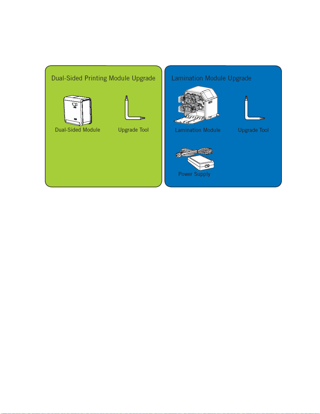
RESTRICTED USE ONLY Fargo Electronics, Inc.
Unpacking the Printer
Display B – See the HDP5000 Printer Installation Guide
HDP5000 High Definition Card Printer/Encoder User Guide (Rev. 1.4)
3-4
Page 48

RESTRICTED USE ONLY Fargo Electronics, Inc.
Choosing a Good Location
Follow these guidelines:
• Place the unit in a location with adequate air circulation to prevent internal heat build-up.
• Use the Printer's dimensions as a guideline for the minimum clearances to the unit.
(Note: Allow for adequate clearance above the unit to accommodate the height of the
unit with its Covers open.)
• Do not install unit near heat sources such as radiators or air ducts or in a place subject to
direct sunlight, excessive dust, mechanical vibration or shock.
About Moisture Condensation
If the unit is brought directly from a cold to a warm location or is placed in a very damp room,
moisture may condense inside the unit. Should this occur, print quality may not be optimum.
Leave the unit turned OFF in a warm, dry room for several hours before using. This will allow
the moisture to evaporate.
Caution: For safety purposes, Ethernet is not intended for a direct connection
outside of the building.
HDP5000 High Definition Card Printer/Encoder User Guide (Rev. 1.4)
3-5
Page 49

RESTRICTED USE ONLY Fargo Electronics, Inc.
Printer Loading Procedures
Loading the Print Ribbon
Note: Fargo Card Printers require highly specialized supplies to function properly.
• To maximize Printer life, reliability, printed card quality and durability, you must use only
Fargo Certified Supplies.
• For this reason, your Fargo warranty is void, where not prohibited by law, if you use nonFargo Certified Supplies.
Step Procedure
1 Load the Print Ribbon into the Print Ribbon Cartridge until the Rolls click.
HDP5000 High Definition Card Printer/Encoder User Guide (Rev. 1.4)
3-6
Page 50

RESTRICTED USE ONLY Fargo Electronics, Inc.
HDP5000 High Definition Card Printer/Encoder User Guide (Rev. 1.4)
3-7
Loading the Print Ribbon (continued)
Step Procedure
2 Tighten the Print Ribbon.
Page 51

RESTRICTED USE ONLY Fargo Electronics, Inc.
HDP5000 High Definition Card Printer/Encoder User Guide (Rev. 1.4)
3-8
Loading the Print Ribbon (continued)
Step Procedure
3 Insert the Print Ribbon Cartridge into the Printer until it clicks.
Page 52

RESTRICTED USE ONLY Fargo Electronics, Inc.
Loading the Clear HDP Transfer Film
Step Procedure
1 Load the HDP Film into the HDP Film Cartridge until the rolls click.
HDP5000 High Definition Card Printer/Encoder User Guide (Rev. 1.4)
3-9
Page 53

RESTRICTED USE ONLY Fargo Electronics, Inc.
HDP5000 High Definition Card Printer/Encoder User Guide (Rev. 1.4)
3-10
Loading the Clear HDP Transfer Film (continued)
Step Procedure
2 Tighten the HDP Film.
Page 54

RESTRICTED USE ONLY Fargo Electronics, Inc.
HDP5000 High Definition Card Printer/Encoder User Guide (Rev. 1.4)
3-11
Loading the Clear HDP Transfer Film (continued)
Step Procedure
3 Insert the HDP Film Cartridge into the Printer until it clicks.
Page 55

RESTRICTED USE ONLY Fargo Electronics, Inc.
HDP5000 High Definition Card Printer/Encoder User Guide (Rev. 1.4)
3-12
Inserting the Card Cleaning Roller
Step Procedure
1 Remove the Card Cleaning Roller from the Print Ribbon packaging and insert
the Cleaning Roller onto the black spindle from the supply pack.
Page 56

RESTRICTED USE ONLY Fargo Electronics, Inc.
Inserting the Card Cleaning Roller (continued)
Step Procedure
2 Remove the protective sleeve from the Card Cleaning Roller.
HDP5000 High Definition Card Printer/Encoder User Guide (Rev. 1.4)
3-13
Page 57

RESTRICTED USE ONLY Fargo Electronics, Inc.
HDP5000 High Definition Card Printer/Encoder User Guide (Rev. 1.4)
3-14
Inserting the Card Cleaning Roller (continued)
Step Procedure
3 Insert the Card Cleaning Roller into the card input area.
Page 58

RESTRICTED USE ONLY Fargo Electronics, Inc.
Loading the Overlaminate
(Note: This procedure only applies to the HDP5000-LC.)
The loading process for both the Thermal Transfer Overlaminate and the PolyGuard™
Overlaminate material is the same. Refer to the following steps to load either type of
overlaminate into the Printer.
Step Procedure
1 Remove the overlaminate from its packaging.
2 Load the Lamination Rolls into the Cartridges until they click.
HDP5000 High Definition Card Printer/Encoder User Guide (Rev. 1.4)
3-15
Page 59

RESTRICTED USE ONLY Fargo Electronics, Inc.
Loading the Overlaminate (continued)
Step Procedure
3 Tighten the Lamination Rolls.
4 Insert the Overlaminate Cartridges into the Lamination Module until they click.
HDP5000 High Definition Card Printer/Encoder User Guide (Rev. 1.4)
3-16
Page 60

RESTRICTED USE ONLY Fargo Electronics, Inc.
HDP5000 High Definition Card Printer/Encoder User Guide (Rev. 1.4)
3-17
Loading the Overlaminate (continued)
Step Procedure
5 Close the Lamination Module Front Cover.
Page 61

RESTRICTED USE ONLY Fargo Electronics, Inc.
Loading the Blank Cards
Step Procedure
1 Load the blank cards into the Card Cartridge, as shown below.
Important: The front of the card must face DOWN. The back of the card
or the magnetic stripe on the card must face UP. The Smart Chip is
loaded on the bottom.
HDP5000 High Definition Card Printer/Encoder User Guide (Rev. 1.4)
3-18
Page 62

RESTRICTED USE ONLY Fargo Electronics, Inc.
Loading the Blank Cards (continued)
Step Procedure
2 Place the Card Input Cartridge onto the Printer until it clicks.
HDP5000 High Definition Card Printer/Encoder User Guide (Rev. 1.4)
3-19
Page 63

RESTRICTED USE ONLY Fargo Electronics, Inc.
Connecting Power to HDP5000 Printer and Lamination Module
Caution: Do not remove the red Warning sticker across the USB connection. Do
not plug in the USB cable until prompted to do so during the installation of the HDP5000
Printer Driver. See the Installing the Printer Driver on Windows XP and Windows 2000
procedure.
Step Procedure
1 The Printer connections are shown in the Displays A to D
2 Use the same procedure for both the Printer and the Lamination Module.
Display A - Connecting the AC power cable to the power supply.
.
HDP5000 High Definition Card Printer/Encoder User Guide (Rev. 1.4)
3-20
Page 64

RESTRICTED USE ONLY Fargo Electronics, Inc.
Connecting Power to HDP5000 Printer and Lamination Module (continued)
Display B - Connecting the other end of the AC power cable to a Surge Protector. See both
notes below.
Note No. 1: Instead of connecting the AC power cable directly into an AC outlet, it is
recommended that a Surge Protector be used to protect against power surges.
Note No. 2: Some buildings have surge protection built into the electrical outlets. Please
consult your building supervisor regarding this feature.
HDP5000 High Definition Card Printer/Encoder User Guide (Rev. 1.4)
3-21
Page 65

RESTRICTED USE ONLY Fargo Electronics, Inc.
Connecting Power to HDP5000 Printer and Lamination Module (continued)
Display C - Connecting the plug from the power supply to the Printer, as shown below.
Display D - Connecting the plug from the power supply to the Lamination Module, as shown
below. The Printer must be attached.
HDP5000 High Definition Card Printer/Encoder User Guide (Rev. 1.4)
3-22
Page 66

RESTRICTED USE ONLY Fargo Electronics, Inc.
Printer Driver Installation Procedures
Installation Procedures
Installing the HDP5000 Printer Driver
Step Procedure
1 Close down all programs and insert the Software Installation CD into your
computer’s CD drive. After a few seconds, the CD’s installer program will
automatically open.
Follow the CD’s on-screen Procedures to complete installation.
(Note: If the CD does not automatically open, use “My Computer” or
“Windows Explorer” to view the contents of the CD. Then, double-click on the
Setup.exe file listed on the CD.)
See the next page.
HDP5000 High Definition Card Printer/Encoder User Guide (Rev. 1.4)
3-23
Page 67

RESTRICTED USE ONLY Fargo Electronics, Inc.
Installing the HDP5000 Printer Driver (continued)
Step Procedure
2 Click on the Next button to continue with the installation.
HDP5000 High Definition Card Printer/Encoder User Guide (Rev. 1.4)
3-24
Page 68

RESTRICTED USE ONLY Fargo Electronics, Inc.
Installing the HDP5000 Printer Driver (continued)
Step Procedure
3 a. Read the License Agreement. Select the I accept the terms of the
license agreement option.
b. Click on the Next button to continue with the installation.
HDP5000 High Definition Card Printer/Encoder User Guide (Rev. 1.4)
3-25
Page 69

RESTRICTED USE ONLY Fargo Electronics, Inc.
Installing the HDP5000 Printer Driver (continued)
Step Procedure
4 a. Select Local to install a USB Printer.
OR
b. Select Network and enter an IP Address for the Printer.
HDP5000 High Definition Card Printer/Encoder User Guide (Rev. 1.4)
3-26
Page 70

RESTRICTED USE ONLY Fargo Electronics, Inc.
Installing the HDP5000 Printer Driver (continued)
Step Procedure
5 Click on the Next button to begin the installation.
HDP5000 High Definition Card Printer/Encoder User Guide (Rev. 1.4)
3-27
Page 71

RESTRICTED USE ONLY Fargo Electronics, Inc.
Installing the HDP5000 Printer Driver (continued)
Step Procedure
6 Wait during the installation.
HDP5000 High Definition Card Printer/Encoder User Guide (Rev. 1.4)
3-28
Page 72

RESTRICTED USE ONLY Fargo Electronics, Inc.
Installing the HDP5000 Printer Driver (continued)
Step Procedure
7
Applies to USB Printer installation:
Connect the USB cable to both the PC and the Printer.
HDP5000 High Definition Card Printer/Encoder User Guide (Rev. 1.4)
3-29
Page 73

RESTRICTED USE ONLY Fargo Electronics, Inc.
Installing the HDP5000 Printer Driver (continued)
Step Procedure
8
Applies to USB Printer installation:
a. Select the Printer Port. (Note: You have the option of selecting
the port only IF you click the BACK button from the previous
screen shot; otherwise, this is automatic.)
b. Wait while the Driver components are being copied to your PC.
HDP5000 High Definition Card Printer/Encoder User Guide (Rev. 1.4)
3-30
Page 74

RESTRICTED USE ONLY Fargo Electronics, Inc.
Installing the HDP5000 Printer Driver (continued)
Step Procedure
9 Click the Finish button.
10 Reboot your computer.
11
You have completed this procedure.
HDP5000 High Definition Card Printer/Encoder User Guide (Rev. 1.4)
3-31
Page 75

RESTRICTED USE ONLY Fargo Electronics, Inc.
Printing a Test Print Image
Step Procedure
1 Install the YMCK or YMCKK Ribbon in the Printer for the Test Print.
2 Open the Driver settings.
a. From your computer’s startup menu, select Settings > Printers and Faxes
(Windows XP) or > Printers (Windows 2000).
b. Double click on the HDP5000 Card Printer under the Printer’s window.
c. Select Printing Preferences under the Printer drop-down menu. (Note: This
will bring up the HDP5000 Printing Preferences window.)
3 a. Select the Card tab, and then click on the Test Print button, as shown in
Display A on the next page.
b. When the Test Print button is selected, an image is copied to the Printer.
HDP5000 High Definition Card Printer/Encoder User Guide (Rev. 1.4)
3-32
Page 76

RESTRICTED USE ONLY Fargo Electronics, Inc.
Printing a Test Print Image (continued)
Step Procedure
4 This completes the HDP5000 High Definition Card Printer/Encoder Installation
Guide.
HDP5000 High Definition Card Printer/Encoder User Guide (Rev. 1.4)
3-33
Page 77

RESTRICTED USE ONLY Fargo Electronics, Inc.
Section 4: Accessory Procedures
Safety Messages (review carefully)
Symbol Critical Instructions for Safety purposes
Danger:
Caution:
Failure to follow these installation guidelines can result in
death or serious injury.
Information that raises potential safety issues is indicated by a
warning symbol (as shown to the left).
• To prevent personal injury, refer to the following safety
messages before performing an operation preceded by this
symbol.
• To prevent personal injury, always remove the power cord
prior to performing repair procedures, unless otherwise
specified.
This device is electrostatically sensitive. It may be damaged if
exposed to static electricity discharges.
Information that raises potential electrostatic safety issues is
indicated by a warning symbol (as shown to the left).
• To prevent equipment or media damage, refer to the
following safety messages before performing an operation
preceded by this symbol.
• To prevent equipment or media damage, observe all
established Electrostatic Discharge (ESD) procedures while
handling cables in or near the Circuit Board and Printhead
Assemblies.
• To prevent equipment or media damage, always wear an
appropriate personal grounding device (e.g., a high quality wrist
strap grounded to avoid potential damage).
• To prevent equipment or media damage, always remove the
Ribbon and Cards from the Printer before making any repairs,
unless otherwise specified.
• To prevent equipment or media damage, take jewelry off of
fingers and hands, as well as thoroughly clean hands to remove
oil and debris before working on the Printer.
HDP5000 High Definition Card Printer/Encoder User Guide (Rev. 1.4)
4-1
Page 78

RESTRICTED USE ONLY Fargo Electronics, Inc.
Using the Security Lock Slot on the HDP5000
Important: Compatible locks are not sold by Fargo Electronics; however, they are readily
available from computer stores.
HDP5000 High Definition Card Printer/Encoder User Guide (Rev. 1.4)
4-2
Page 79

RESTRICTED USE ONLY Fargo Electronics, Inc.
HDP5000 High Definition Card Printer/Encoder User Guide (Rev. 1.4)
4-3
Using the Security Lock Slot on the HDP5000 (continued)
The HDP5000 Printer has a Security Lock Slot located in the back lip of the metal chassis to
accommodate a standard laptop security lock.
• To prevent unauthorized removal of the HDP5000, attach an industry standard security
cable to an immovable object and then lock the cable to the Security Lock Slot. (Note:
Fargo does not sell any type of locking device, but provides this feature for your added
security.)
• The lock slot has a plastic covering that needs to be penetrated by the lock. (Note:
Simply push the lock end into the slot with adequate force to break the protective film.)
Follow the locking procedure recommended by the lock vendor.
Page 80

RESTRICTED USE ONLY Fargo Electronics, Inc.
Installation and Removal Procedures Flipper and
Lamination Modules
Removing the Output Side Upgrade Cover
Tools needed: Press the Release tab with a flat blade. Use the Snap and Clip process.
Estimated Repair Time: 1 minute
Step Procedure
1
Caution: Power off the Printer by unplugging the power cord from
the Printer.
2 Press the release tab in back while simultaneously pulling at the center of the
bottom edge.
3 Reverse instructions to re-assemble. Leave it off if your printer is upgraded for
the Flipper or Lamination Module.
HDP5000 High Definition Card Printer/Encoder User Guide (Rev. 1.4)
4-4
Page 81

RESTRICTED USE ONLY Fargo Electronics, Inc.
Installing the Flipper Module Accessory
Parts included: Flipper Module Accessory Kit, PCB-INTF Board, Torx tool and screws
Tools needed: Torx Tool (included in kit)
Estimated Repair Time: 20 minutes
Step Procedure
1
Caution: Power off the Printer by unplugging the power cord from
the Printer.
2 Remove all USB, Serial, Ethernet communication connections. Remove the
Card Output Hopper.
Important: Do not remove the Covers for this procedure.
3 The Flipper Module is installed at the output side of the Printer.
If there is a Lamination Module attached, the Flipper Module is placed in
between the Printer and Lamination Module.
4 a. Remove the Output Side Upgrade Cover (D910139-01).
b. Release the latch on the upgrade cover.
c. Pull on the bottom of the upgrade cover to remove it from the printer.
5 a. Turn the Printer and the Flipper Module on their back.
b. Use the Torx tool provided to remove the two (2) screws from the bottom
of the Flipper Module. Save the screws for later for reattachment.
6 Position the Flipper Module attachment tabs and the PCB-INTF Board into
the appropriate slots at the base of Printer. See Display A (below).
7 Use the two (2) screws to attach the Flipper Module to the Printer. Please
refer to the pictures below.
Continued on the next page
HDP5000 High Definition Card Printer/Encoder User Guide (Rev. 1.4)
4-5
Page 82

RESTRICTED USE ONLY Fargo Electronics, Inc.
Flipper Module Accessory (continued)
Display A - Slide the Flipper Module attachment tabs and the PCB-INTF Board into the
appropriate slots at the base of Printer Module. This picture shows the Printer and the Flipper
Module.
HDP5000 High Definition Card Printer/Encoder User Guide (Rev. 1.4)
4-6
Page 83

RESTRICTED USE ONLY Fargo Electronics, Inc.
Installing the Lamination Module Accessory
Parts included: Lamination Module Accessory Kit, PCB-INTF Board, Torx Tool and screws
Tools needed: Torx Tool (included in kit)
Estimated Repair Time: 10 minutes
Step Procedure
1
Caution: Power off the Printer by unplugging the power cord from
the Printer.
2 Remove the USB, Serial, Ethernet communication connections.
Important: Do not remove the Covers for this procedure.
3 The Lamination Module is installed at the output side of the Flipper Module.
OR
If there is no Flipper Module, it is installed at the output side of the Printer.
Remove the Card Output Hopper.
4 a. Remove the Output Side Upgrade Cover (D910139-01).
b. Release the latch on the Upgrade Cover.
c. Pull on the bottom of the Upgrade Cover to remove it from the printer.
5 a. Turn the Printer and the Flipper Module on their back.
b. Use the Torx tool provided to remove the two (2) screws from the bottom
of the Flipper Module. Save the screws for later for reattachment.
6 Slide the Lamination Module attachment tabs and the PCB-INTF Board into
the appropriate slots at the base of Printer or Flipper Module.
7 Use the two (2) screws provided to attach the Lamination Module to the
Printer. See Display A on the next page.
Continued on the next page
HDP5000 High Definition Card Printer/Encoder User Guide (Rev. 1.4)
4-7
Page 84

RESTRICTED USE ONLY Fargo Electronics, Inc.
Installing the Lamination Module Accessory (continued)
Display - Slide the Lamination Module attachment tabs and the PCB-INTF Board into the
appropriate slots at the base of Printer or Flipper Module. This picture shows the Printer, the
Flipper Module and the Lamination Module.
HDP5000 High Definition Card Printer/Encoder User Guide (Rev. 1.4)
4-8
Page 85

RESTRICTED USE ONLY Fargo Electronics, Inc.
Section 5: General Troubleshooting
The purpose of this section is to provide the User with specific procedures relating to the
LCD Messages, Communication Errors, Card Feeding Errors, Encoding Errors, Printing
Process Errors, Transfer Process Errors and Diagnosing the Image Problems for the
HDP5000.
Important! Fargo Card Printers require highly specialized print Ribbons to function properly.
To maximize Printer life, reliability, printed card quality and durability, you must use only
Fargo Certified Supplies. For this reason, your Fargo warranty is void, where not prohibited
by law, if you use non-Fargo Certified Supplies. To order additional materials, please contact
your authorized reseller.
LCD Messages
The LCD display shows the current status of the Printer. Refer to the cause and solution
tables in this section for all possible LCD messages. (Note: These tables display the LCD
messages in alphabetical order. If the LCD message is communicating an error or requires
an action, these tables will also offer a solution to what should be done.)
HDP5000 High Definition Card Printer/Encoder User Guide (Rev. 1.4)
5-1
Page 86

RESTRICTED USE ONLY Fargo Electronics, Inc.
Safety Messages (review carefully)
Symbol Critical Instructions for Safety purposes
Danger:
Caution:
Failure to follow these installation guidelines can result in
death or serious injury.
Information that raises potential safety issues is indicated by a
warning symbol (as shown to the left).
• To prevent personal injury, refer to the following safety
messages before performing an operation preceded by this
symbol.
• To prevent personal injury, always remove the power cord
prior to performing repair procedures, unless otherwise
specified.
This device is electrostatically sensitive. It may be damaged if
exposed to static electricity discharges.
Information that raises potential electrostatic safety issues is
indicated by a warning symbol (as shown to the left).
• To prevent equipment or media damage, refer to the
following safety messages before performing an operation
preceded by this symbol.
• To prevent equipment or media damage, observe all
established Electrostatic Discharge (ESD) procedures while
handling cables in or near the Circuit Board and Printhead
Assemblies.
• To prevent equipment or media damage, always wear an
appropriate personal grounding device (e.g., a high quality wrist
strap grounded to avoid potential damage).
• To prevent equipment or media damage, always remove the
Ribbon and Cards from the Printer before making any repairs,
unless otherwise specified.
• To prevent equipment or media damage, take jewelry off of
fingers and hands, as well as thoroughly clean hands to remove
oil and debris before working on the Printer.
HDP5000 High Definition Card Printer/Encoder User Guide (Rev. 1.4)
5-2
Page 87

RESTRICTED USE ONLY Fargo Electronics, Inc.
Troubleshooting - LCD and Printer Error Message
Tables.
This section provides two troubleshooting tables for the LCD error messages and the Printer
error messages. Each table uses a 3-column presentation to present a specific LCD or
Printer error message, its cause and its solution.
• This allows the troubleshooter to identify the error and its cause, and then perform the
procedure (provided in the solution column).
• This standard mode of identifying the problem and its solution should provide an efficient
method of troubleshooting this printer.
• If you encounter problems beyond the capabilities of these two error message tables, you
should contact www.fargosupport.com
HDP5000 High Definition Card Printer/Encoder User Guide (Rev. 1.4)
5-3
Page 88

RESTRICTED USE ONLY Fargo Electronics, Inc.
How to use the LCD Error Message Table (example provided)
The PC Error Message in Column 1 (LCD Error Message) provides the Lower Left Corner
Number. This number identifies the PC Error Message screenshot with its respective LCD
Error Message.
• Note the correlation between Column 1 (below) and the PC Error Message window
(below).
• This allows you to correlate the LCD Error Message with the PC Error Message
(identifying number), then troubleshoot your Printer as needed.
Display – Single Example from the LCD Error Message Table
LCD Error Message Cause Solution
Unable to Feed Card
(PC Error Message
Nos. 14
Matches with the
screenshot below.
Display – Unable to Feed Card (screenshot; Lower Left Corner Number, 14)
and 81)
The Printer is unable to feed
a card from the Card
Cartridge.
Verify there are cards in the
cartridge.
Verify cards are not stuck
together or jammed, and they
are the correct thickness.
HDP5000 High Definition Card Printer/Encoder User Guide (Rev. 1.4)
5-4
Page 89

RESTRICTED USE ONLY Fargo Electronics, Inc.
Troubleshooting with the LCD Error Message Table
LCD Error Message Cause Solution
Calibrate Failed
(PC Error Message
No. 155 and 170)
Calibrate Film
(PC Error Message
No. 159)
Calibrate Ribbon
(PC Error Message
Nos. 128 and 170)
Card Feed Stop
(PC Error Message
No. 137)
Card Jam
(PC Error Message
Nos. 82, 112, and
200)
Film or Ribbon calibration
has failed.
Film Sensors need to be
calibrated.
The print Ribbon Sensor is
out of calibration.
The Front Cover was
opened. This caused the
card transfer to stop OR the
pause button was selected.
A card is jammed in the Print
Station or card flipping area
of the Printer.
Verify the film is installed
correctly and there is not a
Ribbon installed. If this
problem persists, call for
technical assistance.
Select Cancel and then
perform the Film calibration
procedure.
Select Cancel and then
perform the Ribbon calibration
procedure.
Press Resume or Cancel.
Clear the jam.
Card Jam: Prox
(PC Error Message
No. 86)
HDP5000 High Definition Card Printer/Encoder User Guide (Rev. 1.4)
A card is jammed in the
PROX card encoding area of
the Printer.
Clear the jam.
5-5
Page 90

RESTRICTED USE ONLY Fargo Electronics, Inc.
Troubleshooting with the LCD Error Message Table (continued)
LCD Error Message Cause Solution
Card Jam: Smart
(PC Error Message
No. 85)
Card Jam: Trans
(PC Error Message
No. 83)
Card Not Found
(PC Error Message
No. 69)
Check Film
(PC Error Message
No. 244)
Check Laminate 1
(PC Error Message
Nos. 213 and 231)
A card is jammed in the
smart card encoding area of
the Printer.
Card became jammed in the
Printer during transfer.
Card cannot be found in the
Printer.
The film is not able to move
correctly. Check for
jams/breaks.
The Laminator was unable to
find the mark on the material
in Cartridge 1.
Clear the jam.
Clear the jam.
Verify card not jammed in
Printer and select Cancel.
Check for obstruction. If the
problem persists, call for
technical assistance.
Make sure there are no
obstructions to the Sensor,
and recalibrate the Laminator
Sensor.
Check Laminate 2
(PC Error Message
No. 232)
Clean Printer
(PC Error Message
No. 71)
The Laminator was unable to
find the mark on the material
in Cartridge 2.
For best Printer
performance, replace the
Cleaning Roller Tape
and clean the Printer’s Feed
Rollers and Printhead at this
time.
Make sure there are no
obstructions to the Sensor,
and recalibrate the Laminator
Sensor.
See Cleaning the Printer
.
HDP5000 High Definition Card Printer/Encoder User Guide (Rev. 1.4)
5-6
Page 91

RESTRICTED USE ONLY Fargo Electronics, Inc.
Troubleshooting with the LCD Error Message Table (continued)
LCD Error Message Cause Solution
Cover is Open
(PC Error Message
No. 46)
E-Card Encoder
Startup Error
(PC Error Message
No. 141)
E-Card Startup Error
(PC Error Message
No. 141)
EEPROM Corrupt
(PC Error Message
Nos. 38, 39, 40, and
144)
Ejecting Card
(PC Error Message
No. 72)
The Cover was left open. Ensure that the Cover is
properly closed.
A problem was detected
during Printer start-up.
A problem was detected
during Printer start-up.
EEPROM restored with
factory default values.
The card has been ejected
already.
Reset the Printer and try
again. If this problem persists,
call for technical assistance.
Reset the Printer and try
again. If this problem persists,
call for technical assistance.
If changes were made, then go
into the setting values and
reset these numbers.
Click OK to clear the
message. The User might
want to know that a card has
been sent to the reject bin, or
out of the printer, and is either
incomplete or posses a
security risk if not disposed of
properly.
HDP5000 High Definition Card Printer/Encoder User Guide (Rev. 1.4)
5-7
Page 92

RESTRICTED USE ONLY Fargo Electronics, Inc.
Troubleshooting with the LCD Error Message Table (continued)
LCD Error Message Cause Solution
Empty Reject Bin
(PC Error Message
No. 265)
Failed To Initialize
(PC Error Message
No. 141)
Film Align Error
(PC Error Message
Nos. 26 and 176)
Film Break/Jam
(PC Error Message
No. 158)
The reject bin is full. Remove the large number of
rejected cards from the reject
bin.
Click OK to clear the
notification message. (Note:
In some cases, rejected cards
are incomplete or pose a
security risk, and should be
disposed of properly.)
A problem was detected
during Printer start-up.
The film is not able to move
correctly. Check for
jams/breaks.
The film is not able to move
correctly. Check for
jams/breaks.
Reset the Printer and try
again. If this problem persists,
call for technical assistance.
Check for obstruction. If the
problem persists, call for
technical assistance.
Check for obstruction. If the
problem persists, call for
technical assistance.
Film Low
(PC Error Message
No. 156)
Film Out
(PC Error Message
Nos. 156 and 157)
HDP5000 High Definition Card Printer/Encoder User Guide (Rev. 1.4)
The HDP film will soon run
out.
The HDP film has run out. Install a new roll of film and
If printing a large number of
cards, replace the Film now or
monitor the Printer until the
Film is gone and install a new
Film.
press Resume to continue or
Cancel to reset.
5-8
Page 93

RESTRICTED USE ONLY Fargo Electronics, Inc.
Troubleshooting with the LCD Error Message Table (continued)
LCD Error Message Cause Solution
Film: Wrong Material
(PC Error Message
No. 173)
Flipper Jam
(PC Error Message
Nos. 74 and 199)
The HDP Film is not installed
properly or has been
damaged.
A card is jammed in the card
flipping area of the Printer.
Verify the correct film is
installed in the film Cartridge.
Open the Printer's Flipping
Module Cover.
Clear any cards in the Flipping
Module by opening the
Printers Cover and using the
Forward and/or Back buttons
located on the Printer’s Front
Cover.
Ensure that the Flipper Module
can rotate freely. Close the
Printer's Flipping Module
Cover.
Press the Resume button on
the Printer’s Front Cover to
continue printing.
To cancel the print, press the
Cancel Print button from the
Driver's display dialog.
Head Loading
(PC Error Message
No. 111)
HDP5000 High Definition Card Printer/Encoder User Guide (Rev. 1.4)
An unrecoverable error has
occurred during printing.
Reset the Printer and try
again. If this problem persists,
call for technical assistance.
5-9
Page 94

RESTRICTED USE ONLY Fargo Electronics, Inc.
Troubleshooting with the LCD Error Message Table (continued)
LCD Error Message Cause Solution
Head Resistance
(PC Error Message
No. 6)
Head Sensor Error
(PC Error Message
No. 8)
Head Voltage Err
(PC Error Message
Nos. 103 and 105)
Headlift Error
(PC Error Message
Nos. 102, 103, 104,
and 105)
The EE setting in Driver for
head resistance is out of
range.
The Printhead Temperature
Sensor is not functioning or
is not connected properly.
OR
The Printhead is not cooling
properly.
A hardware fault has
prevented setting the correct
Printhead voltage.
This is a problem with the
Printhead Lift or Transfer
Roller Headlift.
Enter a value for head
resistance in the EE settings in
the Driver.
Reset the correct value
according to the steps in the
Troubleshooting Section.
If this problem persists, call for
technical assistance.
If the problem persists, call for
technical assistance.
Reset the Printer and try
again.
If this problem persists, call for
technical assistance.
Reset the Printer and try
again.
If this problem persists, call for
technical assistance.
Heater Error
(PC Error Message
No. 161)
HDP5000 High Definition Card Printer/Encoder User Guide (Rev. 1.4)
The Transfer Heater Roller is
too hot.
Reset the Printer and try
again.
If this problem persists, call for
technical assistance.
5-10
Page 95

RESTRICTED USE ONLY Fargo Electronics, Inc.
Troubleshooting with the LCD Error Message Table (continued)
LCD Error Message Cause Solution
Invalid Film
(PC Error Message
Nos. 94, 95, 96, 164,
165, and 166)
Invalid Password
(PC Error Message
No. 136)
Invalid Ribbon
(PC Error Message
No. 93)
Job Data Error
(PC Error Message
No. 106)
Lam 1 Tag Err
(PC Error Message
No. 259)
An unauthorized film is
installed in the Printer.
Printing disabled at this time. Press Cancel to abort this
An unauthorized Ribbon is
installed in the Printer.
The print data sent to the
Printer is corrupt or has been
interrupted.
A RFID read or write error
occurred on Cartridge 1.
Get the correct Film from your
dealer.
print job and then check
security settings at host
computer.
Get the correct Ribbon from
your dealer.
Reset the Printer and try
again.
If this problem persists, call for
technical assistance.
Retry, and if it fails again the
material cannot be used.
Lam 2 Tag Err
(PC Error Message
No. 260)
Lam Async Error
(PC Error Message
No. 245)
HDP5000 High Definition Card Printer/Encoder User Guide (Rev. 1.4)
A RFID read or write error
occurred on Cartridge 2.
The Printer timed out waiting
for communication from the
Laminator.
Retry, and if it fails again the
material cannot be used.
Check Lam power/connections
and restart the Printer.
5-11
Page 96

RESTRICTED USE ONLY Fargo Electronics, Inc.
Troubleshooting with the LCD Error Message Table (continued)
LCD Error Message Cause Solution
Lam Card Jam
(PC Error Message
No. 53, 212, 214, and
215)
Lam Check Card
(PC Error Message
No. 213)
Lam Com Error
(PC Error Message
No. 246)
Lam Error
(PC Error Message
Nos. 237 and 238)52
Lam Card Not
Ejected
(PC Error Message
No. 216)
A jam occurred somewhere
between the Printer and the
Laminator.
A jam occurred inside the
Laminator.
There was a communication
failure between the Printer
and Laminator.
A generic unknown error as
occurred.
The card is not ejected from
the Laminator.
Open covers and clear the
obstruction/jam.
Open Lam cover and clear the
obstruction.
Check Lam power/connections
and restart the Printer.
Reset the Printer and try
again. If this problem persists,
call for technical assistance.
The Lamination material is
stuck to the card.
Lam Handler Startup
Error
(PC Error Message
No. 66)
HDP5000 High Definition Card Printer/Encoder User Guide (Rev. 1.4)
A problem was detected
during Printer start-up.
Reset the Printer and try
again.
If this problem persists, call for
technical assistance.
5-12
Page 97

RESTRICTED USE ONLY Fargo Electronics, Inc.
Troubleshooting with the LCD Error Message Table (continued)
LCD Error Message Cause Solution
Lam Handler Startup
Error
(PC Error Message
No. 141)
Lam Internal Error
(PC Error Message
No. 48)
Lam No Film
(PC Error Message
No. 157)
Lam Timeout
(PC Error Message
No. 247)
Lam1 Wrong Film
(PC Error Message
No. 233)
After powering up the
Printer, the Laminator was
detected, but an error
occurred which would
prevent its use.
A generic unknown error as
occurred in the Laminator.
There is no material loaded
in the Laminator.
The Printer timed out while
processing information
related to the Laminator.
Material in Cartridge 1 of the
Laminator does not match
the material type specified
by the job.
Check Laminator power and
connections and restart the
Printer.
Check Laminator power and
connections and restart the
Printer.
Load Laminator material.
Check Lam power/connections
and restart the Printer.
Make sure Driver material
matches what is actually in the
Laminator.
Lam2 Wrong Film
(PC Error Message
No. 234)
Laminate 1 Bad
(PC Error Message
No. 259 and 261)
HDP5000 High Definition Card Printer/Encoder User Guide (Rev. 1.4)
Material in Cartridge 2 of the
Laminator does not match
the material type specified
by the job.
The Lamination material in
Cartridge 1 is not valid for
this Laminator.
Make sure Driver material
matches what is actually in the
Laminator.
Install valid material.
5-13
Page 98

RESTRICTED USE ONLY Fargo Electronics, Inc.
Troubleshooting with the LCD Error Message Table (continued)
LCD Error Message Cause Solution
Laminate 1 Jam
(PC Error Message
No. 229)
Laminate 1 Low
(PC Error Message
Nos. 239)
Laminate 1 Out
(PC Error Message
No. 208)
Laminate 2 Bad
(PC Error Message
No. 260 and 262)
Laminate 2 Jam
(PC Error Message
No. 230)
Laminate 2 Low
(PC Error Message
No. 240)
A Jam occurred with the
Laminator material in
Cartridge 1.
The material is getting low in
Lamination Cartridge 1.
The Laminate in Cartridge 1
has run out.
The Lamination material in
Cartridge 2 is not valid for
this Laminator.
A Jam occurred with the
Laminator material in
Cartridge 2.
The material is getting low in
Lamination Cartridge 2.
Open Lam cover and clear the
obstruction
Make sure more is on hand for
when it runs out.
Replace it with a new roll of
material.
Install valid material.
Open Lam cover and clear the
obstruction.
Make sure more is on hand for
when it runs out.
Laminate 2 Out
(PC Error Message
No. 209)
HDP5000 High Definition Card Printer/Encoder User Guide (Rev. 1.4)
The Laminate in Cartridge 2
has run out.
Replace it with a new roll of
material.
5-14
Page 99

RESTRICTED USE ONLY Fargo Electronics, Inc.
Troubleshooting with the LCD Error Message Table (continued)
LCD Error Message Cause Solution
Lm1 Headlift Err
(PC Error Message
No. 217)
Lm2 Headlift Err
(PC Error Message
No. 218)
Mag Encoder Paused
(PC Error Message
No. 143)
Mag Encoder Startup
Error
(PC Error Message
No. 63 and 141)
Mag Verify Error
(PC Error Message
No. 30)
The Laminator failed to
move or sense the lower
(Lam module 1) head.
The Laminator failed to
move or sense the upper
(Lam Module 2) head.
The Magnetic Encoder is in
a pause state.
A problem was detected
during Printer start-up.
Print could not verify MAG
write.
OR
The magnetic stripe was not
encoded properly.
Check head connections and
call for service/repair.
Check head connections, call
for service/repair.
Reset the Printer and try
again.
If this problem persists, call for
technical assistance.
Check the Cards and click on
Cancel Print.
Multiple Feed
(PC Error Message
No. 70)
HDP5000 High Definition Card Printer/Encoder User Guide (Rev. 1.4)
Multiple cards were fed into
the Printer.
Remove all cards and try
again.
5-15
Page 100

RESTRICTED USE ONLY Fargo Electronics, Inc.
Troubleshooting with the LCD Error Message Table (continued)
LCD Error Message Cause Solution
No E-card Encoder
(PC Error Message
No. 202)
No Film
(PC Error Message
No. 28)
No Flip Module
(PC Error Message
No. 201)
You are trying to send
encoding data, but the
Printer is not configured with
this Encoder type.
Film is not installed in the
Printer.
OR
Film RFID tag is bad.
Two-sided job sent to a onesided Printer.
You are trying to send
encoding data, but the Printer
is not configured with this
Encoder type.
Install the Film and press
Resume.
To cancel the print, press the
Cancel Print button or the
Cancel button located on the
Printer.
Verify the Printer has flipper
capabilities via the LCD Menu.
If Flipper capabilities are
present, ensure that the Print
Both Sides option in the
Driver is set correctly.
Press the Resume button on
the Printer’s Front Cover to
continue printing.
To cancel the print, press the
Cancel Print button from the
Driver’s display dialog.
No Flip Module
(PC Error Message
No. 45 and 201)
HDP5000 High Definition Card Printer/Encoder User Guide (Rev. 1.4)
The desired lamination
requires a Flipper Module.
Change the Cartridge location
of the Lamination material (if it
is dual sided), or buy a Flipper
Module.
5-16
 Loading...