


A
J
T
G
P
W
D
M
B
K
U
H
Q
X
E
N
C
L
V
I
R
Y
S
Z
F
O
1
4
7
2
5
8
0
3
6
9
PDX 2000
SWITCHBOARD
for DUO System
Mi 2453
Mi 2453

INDEX
Introduction 3
Installation and connection 5
Operating functions 9
Operating instructions 9
Operation 10
SAFETY NOTICES
Read the instructions contained in this manual carefully
because they provide important information about safe
installation, use and maintenance. Keep this manual appropriately for future reference.
Install your switchboard in a dry place away from heat
sources or devices that produce heat and magnetic elds.
Do not clean the switchboard with water or chemical sol-
vents, use a dry cloth for cleaning.
This device must be exclusively operated for its intended
use. The manufacturer cannot be held responsible for
possible damage caused by improper, erroneous and
unreasonable use.
Keep packing parts away from children (i.e. plastic bags,
expanded polystyrene, etc.).
Do not open the device when it is ON.
The installation must be made by specialized personnel
in compliance with the regulations in force.
Always refer to specialized personnel in case of breakdown,
irregular operation or change in the installation.
The device complies with the EEC directives (CE European
mark).
Mi 2453
Gb - 2 -

Introduction
4
1
15
14
16
17
6
3
8
5
2
7
9
10
11
12
13
A
JTG
P
W
D
M
B
KUH
Q
X
E
N
C
LVI
R
Y
S
Z
F
O
1
4
7
2
5
8
0
3
6
9
Switchboard PDX2000 is a component of the Digital System
“DUO” and comes with a table adaptor and junction box for
an easy connection to the installation. Equipped with an
alphanumerical keypad, an LCD display and 7 service buttons
suitable for making all the functions. The switchboard can
communicate with 200 users (intercoms or videointercoms)
and with one or more door stations.
Main functions
- Three operating modes: day, night and direct call
- Communication between internal users or internal users
and door stations
- Monitor of one or more door stations
- Inclusion on a busy user
- Booking of calls (it can store up to 50 unanswered calls)
- Selective door lock release
- Users directory
Characteristics (see gure)
1 - Button “hold”. During the conversation with an
internal user or a door station, pressing it, it is possible to hold the conversation in progress and then
resume it by pressing again the same button. The
user in hold is ashing on the display.
2 - Button “ON-OFF”. It allows to power ON and OFF
the switchboard (function day-night).
3 - Button “connect”. It allows to put in communication
2 internal users or a door station with an internal
user.
4 - Button “door opener”. It allows to release the lock
of the door station in conversation in that moment
or that of the last door station from which a call has
been made.
5 - Button “monitor”. It allows to control a door sta-
tion quickly connecting to it (or in case of multiple
entrances. To the last door station from which a
call has been made.
6 - Button “menu”. This is the button which allows
to access all the functions to set and program the
switchboard. To move inside the submenus use
the arrow buttons.
7 - Arrow up (or back).
8 - Arrow down (or forward).
9 - Button “erase”. It allows to erase a character or a
selection during settings or insertion of names.
10 - Button “enter”. It allows to conrm and proceed
to the next entry.
11 - During the normal operations of the switchboard
it allows to actuate the internal relay. During the
insertion of data this button is used to select the type
of character (upper or lower case, numbers, etc.).
12 - Alphanumerical Keypad.
13 - Button “inclusion”. It allows the switchboard
operator to include during a communication in
progress.
14 - Button “reset”. Press this button to restart the
switchboard. During the reset no data will be lost.
15 - LCD Display. It shows data and functions during
the operation of the switchboard or during the
programming.
16 - LED’s to underline the most important functions
of the switchboard.
17 - Memory card socket. Using the memory card it
will be possible to import or export data and load
new software releases.
Mi 2453
Gb - 3 -

Display
21.09.1111.06
Free line
User
name
100
The display is organized into 3 different areas
- Status bar
- Name and address
of internal users
and door stations
- Operating info
Status bar
LED’s
Under the display there are 8 LED’s which indicate some
important functions of the switchboard.
Shows that one or more bookings are present
Shows the presence of a message
Shows that a call is in progress (ashing)
It is shown in the upper part of the display and gives the
following info (from left to right)
Date (day-month-year)
Communication status (see the following icons)
Handset on hook
Handset off hook
Call to or from a user
Communication in progress between switchboard
operator and user or between two users
Call from door station
Communication in progress between switchboard
operator and door station or between door station
and internal user
Shows that the ringer tones of the switchboard
have been excluded (minimum volume)
Shows that the direct call mode of the
switchboard has been activated
Shows an opened door (if this function has
been foreseen in the installation)
Shows that the “diverted to a user” operating
mode of the switchboard has been activated
(if supported by the software version)
Shows the activation of the internal relay in
monostable or bistable operating modes
Memory card inserted (see the following icons)
correctly inserted Reading error
Directory (see the following icons)
Ready
Import
directory
Export
directory
Keypad locked
Time (hours-minutes)
Directory
loading
Directory
sorting
Mi 2453
Gb - 4 -

Installation and connection
LO
LO
GN
C
A1
NC
NO
LI
LI
A
V
A
M
The Switchboard is ready for the installation on a desk.
Fix the junction box to the wall with screws and expansion
plugs or to a wall box (Ø=60mm) and make the connection
according to the installation diagram.
To x the switchboard to the wall it is necessary to dismount the plastic table adaptors and use the same metal
wall brackets. Do not use the junction box with the white
connection cable and make the connections directly to the
terminal board of the switchboard. Check for the correctness of the wiring.
Power-ON the system by connecting the power supplies to
the mains.
Programming
For a correct operation of a digital system “DUO”, it is necessary to program all the devices present in the installation.
Switchboard is programmed from factory with the ad-
dress 201. If it is necessary address can be changed
following the instructions reported on the chapter “PDX
Address”.
In all the internal stations a button, pressing which you
will call the switchboard, must be programmed with the
same address of switchboard (according to the previous
example 201); for programming please follow the procedure indicated in the technical manual which comes with
the product.
Program all the door stations to set them for the pres-
ence of the switchboard.
Attention. All the devices connected to a
DUO system, with the presence of a switch-
board, must have a software release 400 or
higher.
Terminal board
LI / LI Duo line input
LO / LO Duo line output
A / A Auxiliary power input
(12-15Vdc - 0.5A)
C Common contact of internal relay
NC Normally open contact of internal
relay
NO Normally closed contact of internal
relay
V video output for an auxiliary monitor
(unbalanced 75W)
M Video output ground
GN Negative input for a local call
A1 Positive input for a local call
Technical data
Power supply directly from the line
Operating current:
Max: 0.5A
Stand by: 0.04A
OFF (night): 0.02A
Permanent memory for programming data
LCD Display: matrix points 64x128
LED’s: 8
Alphanumerical keypad: 15 buttons
Service buttons: 7
Internal relay: 1
Maximum load contacts relay: 12Vac/12÷24Vdc - 1A
Operating temperature: 0° ÷ +50°C
Maximum admissible humidity: 90%RH
Mi 2453
Gb - 5 -

Table of the maximum permitted distances
PA
SE
PRS210
VD2120..
TD2100PL
CD213..PL
LP
LP
2220
230V
230V
127V
127V
0
0
S1
S2
GN
A1
NO
NC
C
FP
GN
A1
NO
NC
C
CCTV MONITORMonitor power supply
Section* Farsa 2302 cable
2x1mm² - AWG17 2x0.32mm² - AWG22 2x0.2mm² - AWG24
A - D 50 m - 164 ft 10 m - 33 ft 5 m - 17 ft
B 150 m - 492 ft 150 m - 492 ft 150 m - 492 ft
C 150 m - 492 ft 150 m - 492 ft 150 m - 492 ft
E ** 30 m - 98 ft 20 m - 65 ft 20 m - 65 ft
F 150 m - 492 ft 50 m - 164 ft 35 m - 115 ft
* Letters for reference on the diagrams (see pages 7 and 8)
** The sum of all the sections “E” must not exceed 300 meters.
Twisted cable CAT5 cable
Art.2302 Farsa cable
Twisted pair cable specied for the digital installation with DUO systems. The use of inappropriate cables may have an adverse effect on the
performance of the system.
Technical characteristics
Number of conductors: 2
Colour: red and black
Cross-section: 2x1mm² (AWG17)
Material: tinned copper
Twisting pitch: 40mm
Nominal impedance: 100W
Electrical door lock
The video signal may
be disturbed during the
operation of the electrical
lock. To avoid this problem or actuate locks with
characteristics other than
recommended (12Vac
1A max.) an additional
power supply should be
used as indicated in the
diagram below.
It is also recommended to connect one interfer-
ence suppressor (transil) as close as possible to
the terminals of the electrical lock.
Connection to a monitor
With the switchboard it is possible also to get the image from door stations installing the monitor FARFISA art. ST7100CW, the wall bracket
art. WB7262 and the table adaptor art. TA7100W (for a proper installa-
tion and connection please refer to the technical manual of wall bracket).
It is also possible to use a CCTV monitor.
Connection of a CCTV monitor
Attention! Please use a monitor with no earth connection (Class II) or
use a ground loop separator. CCTV monitor can work either in continuous or timed mode. In the case of continuous mode (direct powering
from the main) monitor is still powered-ON also when the door station is
not connected (no image).
In timed mode monitor is powered-ON only when the door station is in
connection (with image). To operate in this way it is necessary to connect the CCTV monitor as shown in the following diagram and program
the internal relay of switchboard as reported in the chapter “Operating
mode of internal relay” (see pag.14).
V
M
C
max.12Vdc
NC
PDX2000
NO
110÷230Vac
Connection of a local calling button
(bell function)
Connecting a button
(FP) between terminals A1 and GN it is
possible to enable the
switchboard ringing
with a different ringing tone and without
engaging the switchboard itself (only bell
function).
Connection of a supplementary
ringing bell or a lamp signaler for
the incoming calls
12Vac; 12÷24Vdc - 1A
By applying a self-powered ringer between
terminals C and NO it is possible to drive to
another room the calls received by the switchboard.
- Contacts C and NO of the relay are open in
idle state and closed in activation mode.
- Contacts C and NC of the relay are closed in
idle state and open in activation mode.
It is possible to program the ON time of the
relay, acting in the proper submenu in the “advanced settings” menu.
Mi 2453
Gb - 6 -

LP
LP
L1
L1
LM
LM
LI LI
LOLOLO
LO
LI LI
LM
LM
A1
GN
LM
LM
A1
GN
FP
FP
A
B
E
E
E
C
CD2131÷38..
TD2100..
EC
EM
S1
S2
EH9262+9083
KM8262+WB8262
KM862
EX3262+WB3262
EX362
EH9262+9083
KM8262+WB8262
KM862
EX3262+WB3262
EX362
F
J1
12345
J1
12345
J1
12345
FP
ML2062+ML2083
ML2262+ML2083
J12=3-4
1
2
3
4
GN
A1
NO
NC
C
L2
L2
VD2121CAG
Art.2221ML
J1
230V
127V
0
LD
LD
LP LP
LM LM
LO
LO
LM
LM
DV2420
D
J1
12345
LM
LM
LO LO
LI LI
2221S
LP
LP
PRI
110V÷240VAC
2221ML
J1
230V
127V
0
LP
LP
LO LO
LI
LI
PDX2000
A
J
T
G
P
W
D
M
B
K
U
H
Q
X
E
N
C
L
V
I
R
Y
S
Z
F
O
1
4
7
2
5
8
0
3
6
9
INTERCOM-VIDEOINTERCOM MULTI WAY SYSTEM WITH 1 MAIN DOOR STATION AND A SWITCHBOARD
DV2421P
1-2 termination 47W
3-4 termination 70W
4-5 termination 100W
DV2422A
2-3 open line (default)
J1
12345
DV2420
12345
J1
2-3 open line (default)
VD2120..
SE
230V
127V
Note. Remove the impedance between
the 2 terminals LO in the junction box
of switchboard PDX2000.
FP = Floor call push-button (optional)
SE = Electric door lock (12VAC-1A max.)
PA
PA = Door release push-button (optional)
Attention. All the devices connected to a DUO
system, with the presence of a switchboard, must
0
2220S
have a software release 400 or higher.
Mi 2453
Gb - 7 -

L1 L1
L1
L1
LP
LP
(*)
B2
B3
DV2420
J1
12345
LM
LM
LP
LP
LD LD
PDX2000
A
J
T
G
P
W
D
M
B
K
U
H
Q
X
E
N
C
L
V
I
R
Y
S
Z
F
O
1
4
7
2
5
8
0
3
6
9
230V
127V
0
PRS210
LI
LI
LI
LI
LO
LO
CONNECTION OF A SWITCHBOARD IN A MULTI WAY SYSTEM WITH 2 SECONDARY LINES CONNECTED
L1
L1
(*)
E
DV2420
DV2422A
J1
12345
J1
12345
LM
LM
LP
LP
LD LD
PDX2000
A
J
T
G
P
W
D
M
B
K
U
H
Q
X
E
N
C
L
V
I
R
Y
S
Z
F
O
1
4
7
2
5
8
0
3
6
9
230V
127V
0
PRS210
LI
LI
LI
LI
L1
L1
B
LI
LI
LO LO
L2 L2 L1 L1
LP
LP
TO 2 MAIN DOOR STATIONS.
Example 1. Serial connection of the DUO line to the exchanger switchboard.
secondary line “a”
2273
L2
ON
SW2
OFF
4321
secondary line “b”
LP LP
B1
2221ML
230V
127V
0
ON
SW2
ON
4321
2273
L2L2L2
Note. Remove the impedance
between the 2 terminals LO in
the junction box of switchboard.
B
distances B1, B2 and B3
main door station “2”
main door station “1”
B1+B2+B3 = B
Note. Circled letters are diagram reference for the computation of the distances (see conductor table on page 6).
Example 2. Connection of the switchboard to the DUO line using a line distributor DV2422A
secondary line “a”
secondary line “b”
is equal to the sum of
ON
SW2
2273
L2 L2
OFF
4321
LP LP
2221ML
230V
127V
0
Mi 2453
Gb - 8 -
ON
4321
SW2
ON
2273
main door station “2” main door station “1”

Operating functions
-OFF
Keypad lock
Silent
Device Manager
A
JTG
P
W
D
M
B
KUH
Q
X
E
N
C
LVI
R
Y
S
Z
F
O
1
4
7
2
5
8
0
3
6
9
OFF
Silent
- Keypad lock
Device Manager
A
JTG
P
W
D
M
B
KUH
Q
X
E
N
C
LVI
R
Y
S
Z
F
O
1
4
7
2
5
8
0
3
6
9
OFF
- Silent
Keypad lock
Device Manager
Keypad lock
Silent
- Ringer ON
Device Manager
Back
Normal
- Direct dialling
Mode
Door Stations
Booking
- Mode
Menu
Back
Direct dialling
- Normal
Mode
Door Stations
Booking
- Mode
Menu
The switchboard can operate in the following operating mode:
OFF, ON and Direct Call.
Switchboard OFF (night)
Switchboard is not operative while the other devices of the
system still continue to work as intended. All the call directed
to the switchboard will be lost.
Switchboard ON (day)
All the call either originated by the door stations or by internal
users are intercepted by the switchboard except those made
by the secondary door stations which can be managed by a
secondary switchboard (if present in the installation).
Direct Call
Enabling this function all the call originated by the door
stations are diverted directly to the internal users without being
intercepted by the switchboard. Switchboard will handle only
the call from internal users and is able to manage bookings
and make an inclusions to a communication in progress.
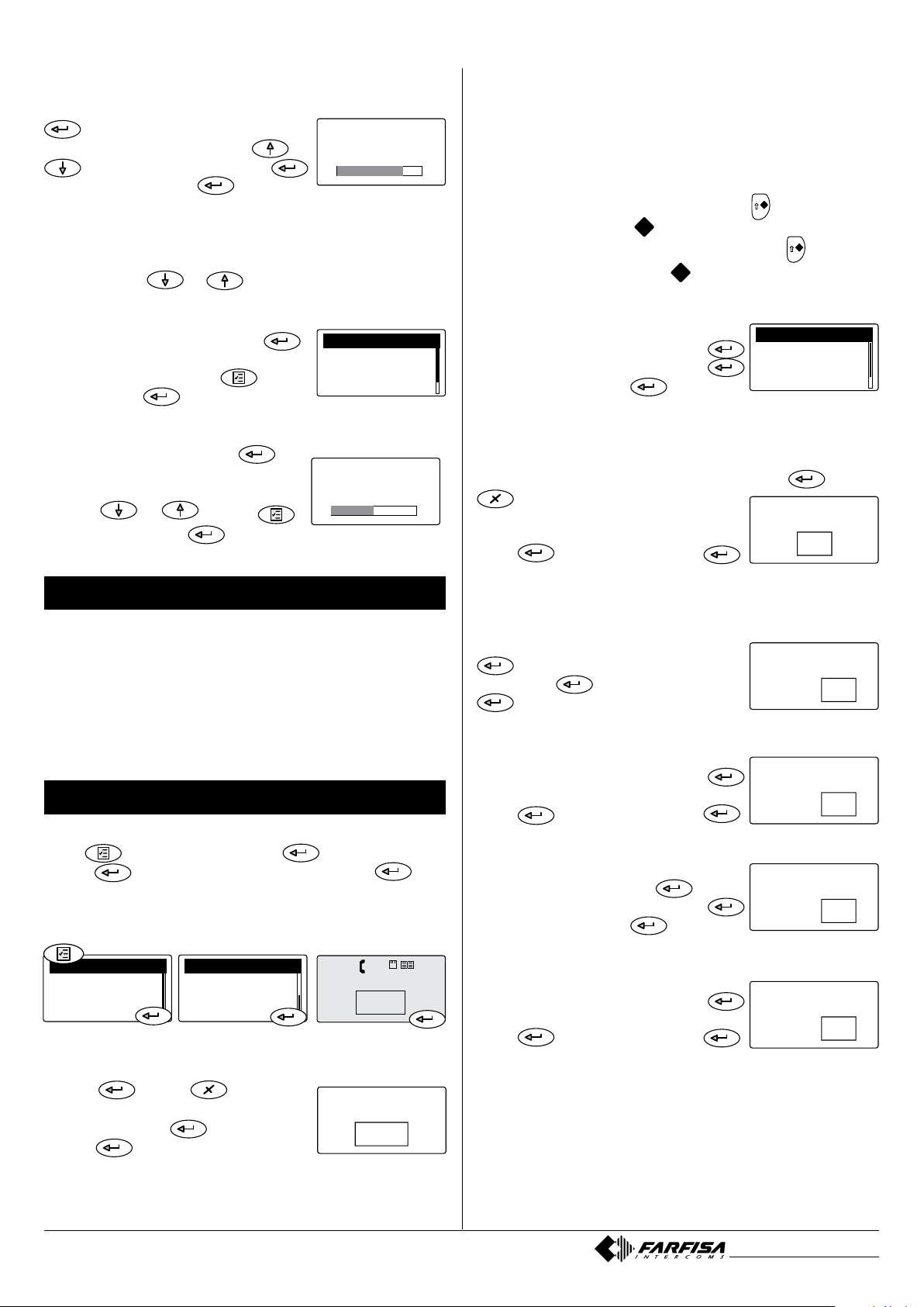
Operating instructions
Power-OFF
Keep pressed the button until the switchboard switches
OFF or when the “device manager” menu appears select
power “OFF” and then press
will not be lost.
Power-ON
Keep pressed the button for some seconds, the switchboard powers ON and starts to operate according to the
previous settings.
Device manager
When the switchboard is ON, pressing shortly the button
to display the “Device Manager” menu; in the menu are
listed the following functions: Power-OFF, keypad lock, ringer
tones OFF, ringer tones ON and software release.
. Already stored bookings
Ringer tones OFF and ON
To set OFF (or ON) all the ringer tones of the switchboard it is
necessary: - access the menu “Device Manager” by pressing
shortly the button
- select “Silent” - press ; LED
will light-ON. To activate again the ringer tones select “Ringer
ON” and press
; LED switches-OFF.
Release Software
To display the software release of the switchboard select
“release” and press
. To exit this page press .
Operating Modes
Enable Direct Call
To enable the Direct Call function it is necessary: press
- select “Mode” - press - select “Direct dialling” - press
; LED will light-ON showing that the Direct Call
function has been activated
Note: in case of power failure or switching-OFF the
switchboard, the function Direct Call remains stored and
will be activated again at the next power-ON.
Back to the operating mode “DAY”
To disable the Direct Call function and operate in “DAY” mode
it is necessary: - press - select “Mode” – press
- select “Normal” - press
; LED switches-OFF.
Keypad lock
Activating this function, the keypad of the switchboard is
locked, it is only possible answer to the incoming calls from
door stations or internal users. In “Device Manager” menu
select “keypad lock” and press
appear
. To unlock the keypad press for several seconds
the button .
; on the display will
Mi 2453
Gb - 9 -

Operations
A
JTG
P
W
D
M
B
KUH
Q
X
E
N
C
LVI
R
Y
S
Z
F
O
1
4
7
2
5
8
0
3
6
9
21.09.1111.06
Brown
Alfred
102
C
HIAMA
102
123
456
789
0
21.09.1111.06
102
231
Alfred Brown
Entrance
Oxford street
A
JTG
P
W
D
M
B
KUH
Q
X
E
N
C
LVI
R
Y
S
Z
F
O
1
4
7
2
5
8
0
3
6
9
21.09.1111.06
Alfred Brown
102
Entrance
Oxford street
231
21.09.1111.06
Free line
102
21.09.1111.06
Brown
Alfred
102
21.09.1111.06
Brown
Alfred
102
A
JTG
P
W
D
M
B
KUH
Q
X
E
N
C
LVI
R
Y
S
Z
F
O
1
4
7
2
5
8
0
3
6
9
D
R
I
N
-
D
R
I
N
A
JTG
P
W
D
M
B
KUH
Q
X
E
N
C
LVI
R
Y
S
Z
F
O
1
4
7
2
5
8
0
3
6
9
21.09.1111.06
231
Entrance
Oxford street
1) Main entrance
3) Lincoln street
-2)Oxford street
Door stations
232
233
231
1) Brown Alfred
3) White Te d
-2)Oxford street
Directory
115
109
231
A
JTG
P
W
D
M
B
KUH
Q
X
E
N
C
LVI
R
Y
S
Z
F
O
1
4
7
2
5
8
0
3
6
9
21.09.1111.06
Brown
Alfred
102
Make a call from Switchboard
To make a call from the switchboard to an internal user it
is necessary to dial the number of the required user using
the keypad or select the name of the required user from the
directory (see chapter “directory”) and then press .
Call the switchboard
To call the switchboard from an internal station, it is necessary:
pick-up the handset (or press the button with “Echos”
series);
- if the line is free you will get a dialing tone
- if the line is busy you will get a busy tone
press the button on which the address of the switchboard
has been stored
- if, after about 30 seconds, switchboard operator does
not answer or if it rejects the call, automatically the call
will be stored in a booking queue
- if the line is busy immediately the call is booked on the
switchboard and an acoustic tone will be heard
- if the line is free, switchboard starts ringing and its display
shows the name and the address of the calling user; LED
and light-ON.
pick-up the switchboard handset within 30 seconds to
answer the call. Communication time is about 90 seconds
and during the last 10 seconds an acoustic tone will remind
the communication time is going to expire; if some extra
time is necessary press twice the button .
A
D
B
E
1
2
3
C
F
JTG
M
KUH
N
4
5
6
LVI
O
P
W
Q
X
R
Y
7
8
9
S
Z
0
Note. If, when the door station makes a call, the switchboard
is engaged in a communication with another user or there
is a communication on “hold” or there is communication between two internal users, the switchboard will ring only with
a single tone and LED
lights-ON for all the time of the
call. To communicate with the door station it is necessary to
close all the communications in progress.
Connection of the switchboard to the door stations
At any moment it is possible to monitor the door stations
pressing the button . If in the installation there are more
door stations, pressing the button
be connected with the last door station which has made a
call. For a selective connection with a specic door station
it is necessary to operate as described in the following:
pick-up the handset, dial the address of the door station you
want to monitor (e.g.:231) and press to be connected
only video with the door station (press
and pick-up again the handset to activate also the audio)
pick-up the handset and dial the address of the door station
you want to monitor (e.g.:231), press to be connected
audio and video with the door station
with the handset on-hook, select the requested door sta-
tion from the door stations list. Press
stations”– press
from the list – press
- select the requested door station
, you get only the video (to en-
able the audio pick-up the handset
With the handset on-hook select the door station from the
directory. Press
- select “Directory” – press
- select the requested door station from the list – press
, you get only the video (to enable the audio pick-up
the handset.
the switchboard will
or replace
- select “Door
Call from door station
Making a call from a door station, the switchboard will ring
with the programmed ringer tone (see “select ringer tones”
chapter), the display will show the name and the address of
the calling door station and of the user the caller is looking
for; LED
Pick-up the handset to talk with the door station, press the
button
Communication will last after 90 seconds or replacing the
handset.
will lights-ON indicating the incoming call.
to release the lock.
Mi 2453
Gb - 10 -

Door lock release
A
JTG
P
W
D
M
B
KUH
Q
X
E
N
C
LVI
R
Y
S
Z
F
O
1
4
7
2
5
8
0
3
6
9
21.09.1111.06
Free line
1) Main entrance
3) Lincoln street
-2)Oxford street
Door stations
232
233
231
1) Brown Alfred
3) White Te d
-2)Oxford street
Directory
115
109
231
21.09.1111.06
231
Entrance
Oxford street
At any moment the lock of a door can be released by pressing the button
a system, pressing
door whose door station is actually in communication with
the switchboard, or, if any communication is in progress,
you will release the lock connected to the last door station
which has made a call. To release selectively the lock, follow the same procedure described in the “Connection of the
switchboard to the door stations” chapter and after getting
audio and video communication (not only video) press the
button
and .
. If more than one door is present in
, you will release the lock of the
nication with the switchboard will be put on hold
- if the address of the internal user which is displayed is
correct press
- if it is wrong press to erase it and dial the correct
address (or select him from the directory)
- if the called user do not answer, press to resume
the line or wait for 30 seconds the call will last; press
to talk again with the door station on hold
- if the called user answers, but do not whishes to talk with
the person asking for him at the door station, wait the user
replace the handset or press to close the call and
get the line; press again to resume the door station
on hold.
- if the called user answers and whishes to talk with the
person asking for him at the door station, press button
; on the display of the switchboard, until the communication lasts, appears the details of the door station
and the internal user in connection.
To interrupt a communication between the door station and
the internal user see chapter “Inclusion”.
Hold state
While the switchboard is in communication with an internal
user or a door station it is possible to hold the communication by pressing the button . The details of user or
door station on hold will be transferred to the bottom of the
display and ashing; the internal user or door station on
hold will get an acoustic or visual signalling. To resume the
communication, press again .
Communication between two internal users
While the switchboard is in communication with an internal
user it is possible to connect him with another internal user
for a period of 60 seconds (which can not be extended) following the below procedure:
press the button ; user actually in communication
with the switchboard will be put on hold receiving a tone
on the handset
dial the address of the second internal user you want to
call (or select him from the directory)
- if the second user do not answer, press to resume
the line or wait for 30 seconds the call will last; press
to talk again with the rst user on hold
- if the second user answers, but do not whishes to talk
with the other user, wait the user replace the handset or
press to close the call and get the line; press again
to resume the rst user on hold
- if the second user answers and whishes to talk with
the other user, press button ; on the display of the
switchboard, until the communication lasts, appears the
details of the two users in connection.
Attention. In some particular installations this feature can
not be guaranteed for all the users.
Inclusion
While a communication between two internal users or between a door station and an internal user is in progress the
switchboard operator can include into the conversation by
picking-up the handset and pressing the button . During
the inclusion, a background tone will warning that a third
person is listening.
To exit from the inclusion mode switchboard operator has to
replace the handset.
To release the line switchboard operator can also interrupt
the communication making rst an inclusion (by pressing
button
in the submenu which appears on the display and nally
pressing
than pressing again the button , selecting YES
.
To interrupt a communication between to users see chapter
“Inclusion”.
External to Internal Communication
While the switchboard is in communication with a door station it is possible to transfer the call to an internal user for
60 seconds (which can be extended) following the below
procedure:
press the button ; door station actually in commu-
Mi 2453
Gb - 11 -

Menu
104
Abc
Brown Alfred
back
- Save
Room number
options
back
Modify
- New
options
Brown Alfred
Abc
- back
Directory
Door Stations
Menu
-1)Smith John
2) Brown Alfred
3) Dylan Lucy
Directory
115
104
109
back
Door Stations
- Directory
Menu
- back
Modify
New
options
Pressing this button you will access to the settings,
programming and operating modes of the switchboard:
Directory, Door Stations, Booking, Operating modes and Settings. To access
to the submenus uses the buttons
and conrm by pressing .
Directory
In the Directory can be stored up to 300 names of users or door
stations with their addresses (e.g.Alfred Brown 104; Entrance
Oxford St.231). To access the directory it is necessary:
- press the button
- select “directory” - press
(all the names stored in the directory will be displayed in
alphabetic order, or you get a blank page if any user has
been previously stored) - press - you access the following functions: Modify, New, Delete, Sort by Name, Sort
by address, List, Details, Export, Import.
Modify a user’s name or user’s address
In the directory select the requested user - press select “modify” - press
- using the button place
the cursor to the last character of the name to be modied
- press several times
name - enter the new name - press
to delete all the characters of the
- cursor automatically moves to the address box - press to erase the
address - enter the correct address - press - cursor
moves to a small box on which there is written the number “0”
(do not change it; only in some specic cases it is possible
to change this number) - press - select “Save” - press
; changing is automatically stored and you will be back
to the directory list.
Delete a user
In the directory select the user to be deleted - press
- select “delete” - press
Yes - press
; user is automatically deleted and you will
- with the button select
be back to the directory list.
Sorting of user’s names
Select the sorting you like (“by name” or “by address”) than
press you will be back to the directory list sorted according to your chose.
Note. While entering or modifying a name it is possible to
change the character’s type by pressing the button
.
Entering names and addresses
To enter the user’s names or the door station’s identication
names you can use either the alphanumeric keypad or a
memory card (see chapter “Import/export of names”).
To enter the names by the keypad follow the below instructions:
- after entered the directory menu as
described previously select “New”,
press , enter the user’s or door
station’s name (e.g. Alfred Brown)
using the alphanumerical keypad; in
case of typing error, place the cursor
on the right of the wrong character and
press
- press
the user’s address. Attention: the address to enter must correspond to the
address stored into the device to be
called (Mr. Alfred Brown’s intercoms
or videointercoms address e.g.104)
- after having entered the user’s address press , select “Save” and
press to store the user into the
directory.
To add other users to the directory repeat
the previously described operations.
If it is necessary to store two users with the same address
(wife and husband; professional ofce and apartment) it is
sufcient to create two different users with different name
but with the same address.
to erase it;
to conrm e move to enter
Display of users
The users can be displayed like a list or one by one in details.
Make the choice and press
to be back to the directory.
In both cases to move from one user to another you have to
use the button and .
Import/Export of users to/from the directory
To load in a quick way the directory it is possible to use a
personal computer and a very common writing program like
Block Notes, Word pad or similar. Users must be written in
the following way:
“User’s name and surname” followed by a “semicolon” (;)
“blank space” and than “user’s address” (3 gures) followed
by a “semicolon” (;) “blank space” and than “room number”
(normally write “0”, only in some specic cases this number
can be changed) followed by a “semicolon” (;), than press
to insert another user.
E.g.: Alfred Brown; 104; 0;
Ted White; 110; 0;
.........
Save the le into the memory card with the name: contacts
(pay attention that switchboard recognizes only a le named
contacts.txt; the name of the le must be written using only
lower cases letters) – insert the card into the proper socket
of the switchboard – open the directory menu – press
- select “import” – on the display appears: “procedure in
progress: please wait” and a loading bar will show the per-
centage of already loaded data. Once nished the loading
procedure the system will go back to the directory.
If the loading procedure doesn’t start, please control for the
presence in the memory card of the le: contacts.txt (written
with lower cases letters and the extension .txt), please
double check for the correctness of data written inside the
le (see above example and take care that after the name
and surname there is a semicolon as separator followed by
Mi 2453
Gb - 12 -

a blank space than a 3 gures address, again a semicolon
10
:
44
1) Main entrance
3) Lincoln street
-2)Oxford street
Door stations
232
233
231
back
Directory
- Door stations
Menu
- back
Sort by name
Sort by address
options
- (104)15:40 11/11/11
(88) 12:19 12/11/11
Booking
Directory
Door stations
- Booking
Menu
- back
List
Details
options
- indietro
Ora
Data
Impostazioni
Prenotazioni
Modalità
-Impostazioni
Menu
27
..
09 11
Italiano
- Inglese
Lingua
- Badinerie
Nokia Tune
Mozart 40
Call from door station
Programming number of
ringer tones
1
-Call from door station
Call from user
Call from swbd.
Ringtone type
as separator followed by a blank space and 1 gure number
than a semicolon as separator without any blank space.
Very important is that for each user there must be exactly 3
semicolon as separators). Finally check that the program
used to write the le will create a standard .txt le.
To download the directory to the memory card, select “export”. Wait the end of downloading to remove the memory
card from the socket. Switchboard will cerate in the memory
card the le contacts_ddmmyyyy.txt, were dd is the current
day of the month, mm is the current month of the year and
yyyy are the current year.
Door stations
Operating Mode
You access the operating modes of switchboard (“day” or
“direct calling”). See “enable direct call” and “back to the
operating mode - day”.
Settings
In this menu it is displayed the list of settings. Time, Date,
Language, Ringing Tones, Ringing Volume, Backlighting,
LCD Contrast and Advanced Settings.
Selecting “Door Stations” and pressing you will access
the list of door stations of the system (if previously stored in
the directory). Press to access the submenu were it
is possible to chose the sorting mode of the list (same procedure described in the chapter “directory”) or press
to connect to the selected door station (as described in the
chapter “Connection of the switchboard to the door stations”).
Attention. The list of door stations of the system is automatically created from the users stored in the directory. All
the users with addresses from 231 to 250 will considered
as door stations.
Booking management
The presence of a booking queue in the switchboard is
indicated by the ashing LED .
To display the booking list it is necessary:
press the button - select “Booking” - press ; the
booking list will be displayed with the details of the user’s
address, date and hour of calling;
Time
Select “Time” and press - with the keypad enter the
actual hour - press - with the
keypad enter the actual minutes - press
- select “save” - press - the
new time is stored and you will be back
on the previous page.
Date
- Select “Date” and press - with the keypad enter the
actual day of the month - press - with the keypad enter the actual month of the year - press
- with the keypad enter the two
last gures of the actual year - press
- select “save” - press - the
new date is stored and you will be back
on the previous page.
Language
- Select “Language” and press from the list select the desired language
(from the factory it is selected Italian)
- press
- the new language is stored and
you will be back on the previous page.
- select “save” - press
pick-up the handset and press to call the currently
selected users from the booking list
- if the user doesn’t answer he remains booked
- if the user answers the booking will be cancelled.
At the end of conversation replace the handset.
To cancel a booking without calling back the user it is
necessary:
- select the user’s name from the booking list - press
- select “delete” - press - using the button select
“Yes” - press
.
To exit the booking menu press the button - select
“back” or “exit” - press .
Select ringer tones and number of ringing
Switchboard can receive 4 different kinds of call (call from
door station, call from user, call from another switchboard
and local call using a button connected between GN and
A1). Operating in the following way it is possible to select a
different ringing tone for each call:
- select “Ringing Tones” and press - from the list select
the kind of call which you want to change - press you will hear the actual ringing tone, from the list select the
desired ringing tone - press
which is written the actual number of ringing, if you want
to change it erase the actual number and enter, with the
keypad, the new number (from 1 to 9) - press
“save” - press
.
- you access a page on
- select
Mi 2453
Gb - 13 -
Ringing Volume
Booking
Mode
- Settings
Menu
Programming system
password
1234
-Addit.ringer tone
Monitor door station
Bistable
Relay mode
####
21.09.1111.06
Display backlight
- Advanced
Display contrast
Settings
Programming relay time
activation
30
Restore factory set.
NO
YES
Clear ALL bookings
NO
YES
Delete list
NO
YES
Recovery directory
NO
YES
Ringer tones volume
75%
- Red
Green
Blue
Display backlight
Display contrast
50%
Ringing volume is the same for all the kind of calls.
- To adjust it select “Volume” and press
- an adjusting bar is displayed on
the screen - with the buttons or
adjust the volume - press
- select “save” - press
.
Ringing Tones can be disabled choosing the lowest level of volume in this menu or directly from
the Device Manager menu.
Ringing volume can be also momentarily adjusted acting
on the buttons
or while receiving a call.
Display Backlighting
Select LCD Backlighting - press chose the desired color from the list or
create a new color - press
- select
“save” - press .
Display Contrast
Select LCD Contrast - press - an
adjusting bar is displayed on the screen,
adjust the contrast of LCD acting on the
buttons or - press select “save” - press .
Operating mode of the internal relay.
Relay inside the switchboard (terminal boards C, NC, NO)
can be used for:
- additional ringer for the incoming calls, a lamp signaller
can also be driven
- power-ON a CCTV monitor only during the calls from the
door stations
- bistable relay operated by the button
is activated the LED
will light-Up
- monostable relay operated by the button
relay is activated the LED
will light-Up, timing of relay
; when the relay
; when the
should be set according the instructions of chapter “Timing
of internal relay”.
To set the operating mode it is necessary: - select “Relay mode” - press
- select the requested mode - press
- select “save” - press .
Timing of internal relay
To set the activation time of relay, only when the relay operates as “additional ringer tone” and “monostable”, it
is necessary: - select “Relay timing” – press - press
to erase the previous programmed
activation time – enter the new activation
time in seconds (from 1sec to 99 sec.) press
- select “save” - press .
Advanced and System settings
Advanced and system settings are fundamental for the
correct working of the system, therefore they are accessible only entering a 4-digit password. From the factory the
password is 1234. It is advisable to change it with a personal one (see chapter “Password changing”).
Attention. It advisable to write down the new password
and keep it in a safe place; If you lose the password you
must ask a new one directly to ACI FARFISA.
Advanced
To access the advanced menu you should:
Press - select “settings” - press - select “advanced”
- press
following functions will be listed: Password, Relay mode,
Relay timing, Restore factory settings, Clear all bookings,
Delete list, Recovery Directory.
Changing Password
To change the password it is necessary: - select “Password”
– press
actual password –enter the new 4-digit
password - press - select “save”
- press .
New password in now stored.
- enter the 4-digit password - press - the
- press to erase the
Factory settings
To restore the factory settings and reset all the data previously programmed (except the directory) it is necessary:
-select “Restore factory settings” - press
- select YES to conrm or NO to
exit - press - select “save” - press
.
Clear all bookings
To cancel all the booking queue:
-select “Clear all bookings” – press
- select YES to conrm or NO to exit press
- select “save” - press .
Erasing completely the directory
To completely erase the directory:
-select “Delete list” - press
- select
YES to conrm or NO to exit - press
- select “save” - press .
Restoring the users’ in the directory
To restore the last erased directory:
-select “Recovery directory” - press
- select YES to conrm or NO to exit press
- select “save” - press .
Mi 2453
Gb - 14 -

System
Booking
Mode
- Settings
Menu
####
21.09.1111.06
Display contrast
Advanced
- System
Settings
Programming PDX
address
201
-Main
Secondary
PDX hierarchy
-Master
Slave
PDX type
Attention. In this submenu there are some parameters whose
changing can affect the correct operation of the system. It is
necessary to modify these parameters only if in the system
there is more than one switchboard. If in the system there
is only one switchboard do not modify any parameter. To
access this submenu it is necessary:
- press
tem” - press
- select “settings” - press - select “sys-
- enter the 4-digit password - press
- the following functions will be listed: PDX address, PDX
hierarchy, PDX type.
PDX address
To change the PDX address, it is necessary: select “PDX
address” - press
- press to erase the previous
address of the switchboard (from the fac-
tory 201) - enter the 3-digit new address
(allowed addresses from 201 to 210) -
press - select “save” - press .
Attention. Internal users must have on their intercom or
videointercom a button coded with the same address of
the switchboard.
PDX Hierarchy
If in an installation there is one or more switchboards on the
main line and other switchboards in one or more secondary
lines it is necessary to set each of them according to the
following instructions:
- set as “Main” those connected to the main line
- set as “Secondary” those connected to the secondary
lines
From the factory all the switchboards are set as “Main”.
Once in the PDX hierarchy menu - press
- select “Main or Secondary” - press
- select “save” - press .
Reset
Reset button is placed on the top of switchboard and can be
operated only with a small stylus. To reset the switchboard
keep pressed it for some seconds (avoiding to make an excessive strength), the switchboard will reboot soon without
losing any data.
D
A
B
E
1
2
3
C
F
M
JTG
KUH
N
4
5
6
LVI
O
P
W
Q
X
R
Y
7
8
9
S
Z
0
Software updating
By means of the memory card it is possible to load in the
switchboard memory new software releases which can be
downloaded from the web site www.acifarsa.it.
To upgrade the software release act as in the following:
- load the new software release into a memory card;
- insert the memory card in the proper socket located on the
bottom of switchboard;
- press reset button (use a suitable stylus and do not make
an excessive strength). Switchboard will reboot loading
the new software version in a few seconds without losing
any data or settings previously stored.
PDX type
If in an installation there are more switchboards at the same
hierarchical level it is necessary to set one of them as “Master” and the others as “Slaves” (for secondary switchboards
this setting is required only for those connected to the same
secondary line; more switchboards connected to a different
secondary lines doesn’t require to be set as “Master” and
“Slave”, on the contrary all of them must be set as “Master”).
From the factory all the switchboards are set as “Master”.
Once in the PDX Type menu - press - select “Master
or Slave” - press - select “save” press .
Mi 2453
Gb - 15 -

Cod. 52704880 Mi 2453
DATA DI ACQUISTO - DATE OF PURCHASE - DATE D’ACHAT -
ACI srl Farsa Intercoms
Via E. Vanoni, 3 • 60027 Osimo (AN) • Italy
Tel: +39 071 7202038 (r.a.) • Fax: +39 071 7202037
La ACI Srl Farsa Intercoms si riserva il diritto di modicare in qualsiasi momento i prodotti qui illustrati.
ACI Srl Farsa Intercoms reserves the right to modify the products illustrated at any time.
La ACI Srl Farsa Intercoms se réserve le droit de modier à tous moments les produits illustrés.
ACI Srl Farsa intercoms se reserva el derecho de modicar en cualquier momento los productos
ilustrados aquí.
E’ reservada à ACI Srl Farsa intercoms o direito de modicar a qualquer momento os produtos aqui
ilustrados.
FECHA DE COMPRA - DATA DE COMPRA - EINKAUFSDATUM
TIMBRO E FIRMA DEL RIVENDITORE
DEALER’S NAME AND ADDRESS
NOM ET ADRESSE DU REVENDEUR
NOMBRE Y DIRECCION DEL DISTRIBUIDOR
CARIMBO E ASSINATURA DO REVENDEDOR
STEMPEL DES HÄNDLERS
Änderungen vorbehalten.
e-mail: info@acifarsa.it • www.acifarsa.it
CERTIFICATO DI GARANZIA
(condizioni valide solo per il Territorio Italiano)
La garanzia ha la durata di 24 mesi dalla data di acquisto, accertata o accer-
tabile, e viene esercitata dalla Ditta rivenditrice e, tramite questa, dai Centri
Assistenza Tecnica Autorizzati ACI Srl Farsa Intercoms.
La garanzia deve essere esercitata, pena la decadenza, entro otto giorni dalla
scoperta del difetto.
LA GARANZIA NON E’ VALIDA SE NON DATATA E VIDIMATA CON TIMBRO
E FIRMA DEL RIVENDITORE ALL’ATTO DELL’ACQUISTO. CERTIFICATO
UNICO ED INSOSTITUIBILE.
MATRICOLA - SET NUMBER - MATRICULE APPAREIL -
N° MATRICULA - N° DE MATRICULA - SERIENNUMMER
Smaltire il dispositivo secondo quanto prescritto dalle norme per la tutela
dell’ambiente.
Dispose of the device in accordance with environmental regulations.
Écouler le dispositif selon tout ce qu’a été prescrit par les règles pour la
tutelle du milieu.
Eliminar el aparato según cuánto prescrito por las normas por la tutela
del entorno.
Disponha do dispositivo conforme regulamentos ambientais.
Werden Sie das Gerät in Übereinstimmung mit Umweltregulierungen los.
Mi 2453
 Loading...