

Page 1
INTERCOMS
2002
88
88
SPRECHANLAGEN
E
ng
D
e
ish
l
t
u
s
c
h
Page 2
INTRODUCTION
EINFÜHRUNG
This edition contains helpful information on the operation and installation of
Farfisa articles.
In order to make the systems work perfectly it is necessary to install only
Farfisa equipment, keeping strictly to the items referred to in each diagram.
Read all the notes carefully, (even the small ones) in each installation
scheme and the working instructions of the system given in the following
pages.
For the sake of clarity, please notice that the sequence of the terminals of
each article
has not been followed. Only the terminal code (letter and/or
number) is valid not the graphic sequence.
The items may have more terminals than the ones in the installation
diagrams. The excess terminals must not be utilized.
Notice to the installer and user
Check the integrity of the device after removing it from the packing.
Packing materials (such as plastic bags, cardboard, polystyrene foam,
etc.) must be kept out of the reach of children.
The manufacturer cannot be held responsible for possible damages
caused by improper, erroneous and unreasonable use.
For correct operation make sure that ventilation or heat dissipation open-
ings and slots are not obstructed.
The cable runs of any intercom unit must be kept separate from the mains
as required by International standards.
In case of breakdown or change in the system consult specialized person-
nel.
It is advisable to provide behind the (fused spur) power supply a disconnect-
ing and safety switch.
Before connecting the unit, make sure its data correspond’s to those of the
mains.
In diesen Unterlagen werden die Betriebsdaten sowie Installationshinweise
der ACI Farfisa Videosprechanlagen beschrieben.
Für den einwandfreien Betrieb der hier beschriebenen Anlagen ist der
Einsatz aller angegebenen Farfisa Originalteile notwendig. Folgen Sie
hierzu genau die entsprechenden Stücklisten die sich bei jedem Schaltplan
befinden.
Lesen Sie sorgfältig alle Bemerkungen und Warnungen, auch die kleinsten. Eine Funktionsbeschreibung der Anlagen finden Sie in den folgenden
Seiten.
Für eine bessere Übersicht der hier vorhandenen Schaltpläne wurde die
Reihenfolge der Anschlußleisten der einzelnen Baugruppen nicht
berücksichtigt. Maßgebend bei den Anschlüsse sind nur die angegebe-
nen Bezeichnungen.
Die eingesetzten Baugruppen können mehrere Anschlußpunkte haben,
als in den Schaltplänen dargestellten. Diese dürfen nicht angeschlossen
werden.
Hinweise für den Installateur und Betreiber
Versichern Sie sich nach dem Auspacken des Geräts, dass dieses
unversehrt ist.
Verpackungsmaterialien (Plastikbeutel, Karton, Polystyrol usw.) nicht in
Kinderhände gelangen lassen, da sie eine potentielle Gefahrenquelle
darstellen.
Der Hersteller lehnt jede Verantwortung für Schäden in Folge von Mißbrauch oder unsachgemäße Benutzung der Anlagen ab.
Belüftungsöffnungen oder Wärmeabführschlitze freihalten, um die Funktionstüchtigkeit des Apparates nicht zu beeinträchtigen.
Die Verlegung der Verbindungskabel für die Türsprechanlagen muß
getrennt von den Starkstromkabeln erfolgen, wie es die VDE Vorschriften
verlangen.
Bei Ausfall oder Änderung der Anlage wenden Sie sich bitte ausschließlich
an das entsprechend ausgebildetes Fachpersonal.
Vor den Netzteilen ist der Einsatz eines entsprechenden Trennschutzschalters und Überspannungsfilter empfohlen.
European Mark of conformity to the EEC
Directives.
Europäisches Markenzeichen zur Bestätigung der Konformität zu den EU-Richtilinien
CE MARK
The CE mark ensures that the product complies with the requirements of the
European Community Directives in force; in particular, Electrical Safety LVD73/23,
Electromagnetic Compatibility EMC89/336 and Telecommunication Terminals
R&TTE99/5 Directives.
As set forth by the Directives, the technical documentation and Conformity Declarations are available in the Company’s offices for verifications and controls by
competent Authorities.
CE-KENNZEICHNUNG
Die CE-Konformitätskennzeichnung zeigt an, dass das Produkt die jeweiligen
Anforderungen der geltenden Richtlinien der Europäischen Gemeinschaft erfüllt.
Hierzu zählen insbesondere die Richtlinien bezüglich der Elektrosicherheit
LVD73/23, der elektromagnetischen Kompatibilität EMC89/336 und der
Telekommu-nikationsterminals R&TTE99/5.
Wie in diesen Richtlinien vorgeschrieben ist, werden die technischen Unterlagen
und die Konformitätserklärungen am Sitz des Herstellers aufbewahrt und den
zuständigen Behörden zwecks Überprüfung und Kontrollen zur Verfügung gestellt.
Bevor Sie die Anlage anschließen vergewissern Sie sich das die Betriebsspannung die der vorhandenen Netzspannung entspricht.
Mark of approval to German regulations.
Markenzeichen zur Bestätigung der Konformität zu den deutschen Bestimmungen
Quality assured firm.
Zertifizierte Qualitätssicherung.
Page 3

TECHNICAL MANUAL
TECHNISCHE UNTERLAGEN
2002 Edition
INDEX
Intercoms.
Telecommunication.
Push-button panels.
Power supplies.
Service modules.
Cable section.
Working instructions.
Troubleshooting.
INSTALLATION DIAGRAMS
4+1 intercoms
- Si 100 Intercoms connected to a door station.
- Si 120 Intercoms connected to two door stations with auto-
matic switching.
- Si 160 Intercom system with one main entrance and additional
entrances (risers of buildings).
- Si 100/EM Intercoms connected to a door station with electronic call and a buzzer from the floor.
- Si 100/SM Intercoms with private conversation module connected to a door station.
Page
16
18
18
19
19
21
22
23
25
27
29
31
Ausgabe 2002
INHALTSVERZEICHNIS
Haustelefone.
2
Telefonanlagen *
5
Türstationen.
6
Netzgeräte.
Servicemodule.
Leitungsdurchmesser.
Funktionsbeschreibung.
Fehlersuche.
SCHALTPLÄNE
Sprechanlagen 4+n
-Si 100 Mehrfamilienhaus-Sprechanlage mit einer Türstation.
-Si 120 Mehrfamilienhaus-Sprechanlage mit zwei umschaltbaren
Türstationen.
-Si 160 Mehrfamilienhaus-Sprechanlage mit Nebentürstationen
und eine gemeinsame Haupttürstation (Treppenhausunterteilung).
- Si 100/EM Mehrfamilienhaus-Sprechanlage mit einer Türstation,
elektronischer Klangruf und Etagenruf.
- Si 100/SM Mehrfamilienhaus-Sprechanlage mit einer Türstation
und Mithörsperre.
Page
2
5
6
17
18
18
20
20
21
22
23
25
27
29
31
Intercommunicanting systems
- Si 210/5 5 intercommunicating intercoms connected to a door
station with individual call.
- Si 220/5 5 intercommunicating intercoms connected to a door
station with individual call and an electronic bell for internal calls.
- Si 230/5 5 intercommunicating intercoms connected to a door
station with common call and electronic bell for internal calls.
- Si 250/5 5 intercommunicating intercoms connected to two
door stations with automatic switching and with individual call.
Electronic bell for internal calls.
- Working diagrams for intercommunicating systems with a door
station and individual call.
- Working diagrams for intercommunicating systems with a door
station and individual call and electronic bell for internal calls.
- Working diagrams for intercommunicating systems with a door
station and common call and electronic bell for internal calls.
1+1 intercom systems
Intercoms.
Push-button panels.
Installation rules.
- Si 21MR/1 Intercoms connected to a door station series Mody.
- Si 22MR/1 Intercoms connected to two door stations series
Mody with automatic switching.
Gegensprechanlagen
32
- Si 210/5 Mehrfamilienhaus-Sprechanlage mit 5 Haustelefone,
33
einer Türstation und internen Gegensprechverkehr.
- Si 220/5 Mehrfamilienhaus-Sprechanlage mit 5 Haustelefone,
35
einer Türstation und internen Gegensprechverkehr mit elektronischem Klangruf für Internrufe.
37
- Si 230/5 Einfamilienhaus-Sprechanlage mit 5 Haustelefone, ei-
ner Türstation und internen Gegensprechverkehr mit elektroni-
39
schem Klangruf für Internrufe.
- Si 250/5 Mehrfamilienhaus-Sprechanlage mit 5 Haustelefone, 2
umschaltbare Türstationen und internen Gegensprechverkehr mit
40
elektronischem Klangruf für Internrufe.
- Anwendungsschaltpläne für Mehrfamilienhaus-Gegensprechan-
41
lagen mit Türstation.
- Anwendungsschaltpläne für Mehrfamilienhaus-Gegensprechan-
42
lagen mit Türstation und elektronischem Klangruf für Internrufe.
- Anwendungsschaltpläne für Einfamilienhaus-Gegensprechanlagen mit Türstation und elektronischem Klangruf für Internrufe.
43
Sprechanlagen 1+n
43
43
Haustelefone.
46
Türstationen.
47
Installationsvorschriften.
48
- Si 100MD Mehrfamilienhaus-Sprechanlage mit einer Türstation
der Serie MODY.
- Si 120MD Mehrfamilienhaus-Sprechanlage mit zwei umschaltbaren Türstationen der Serie MODY.
32
33
35
37
39
40
41
42
43
43
43
46
47
48
* Diese Anlagen sind z.zt. nicht für die Bundesrepublik Deutschland
zugelassen.
1
8 GbD-'02
Page 4
INTERCOMS /
HAUSTELEFONE
Series
Serie
Project
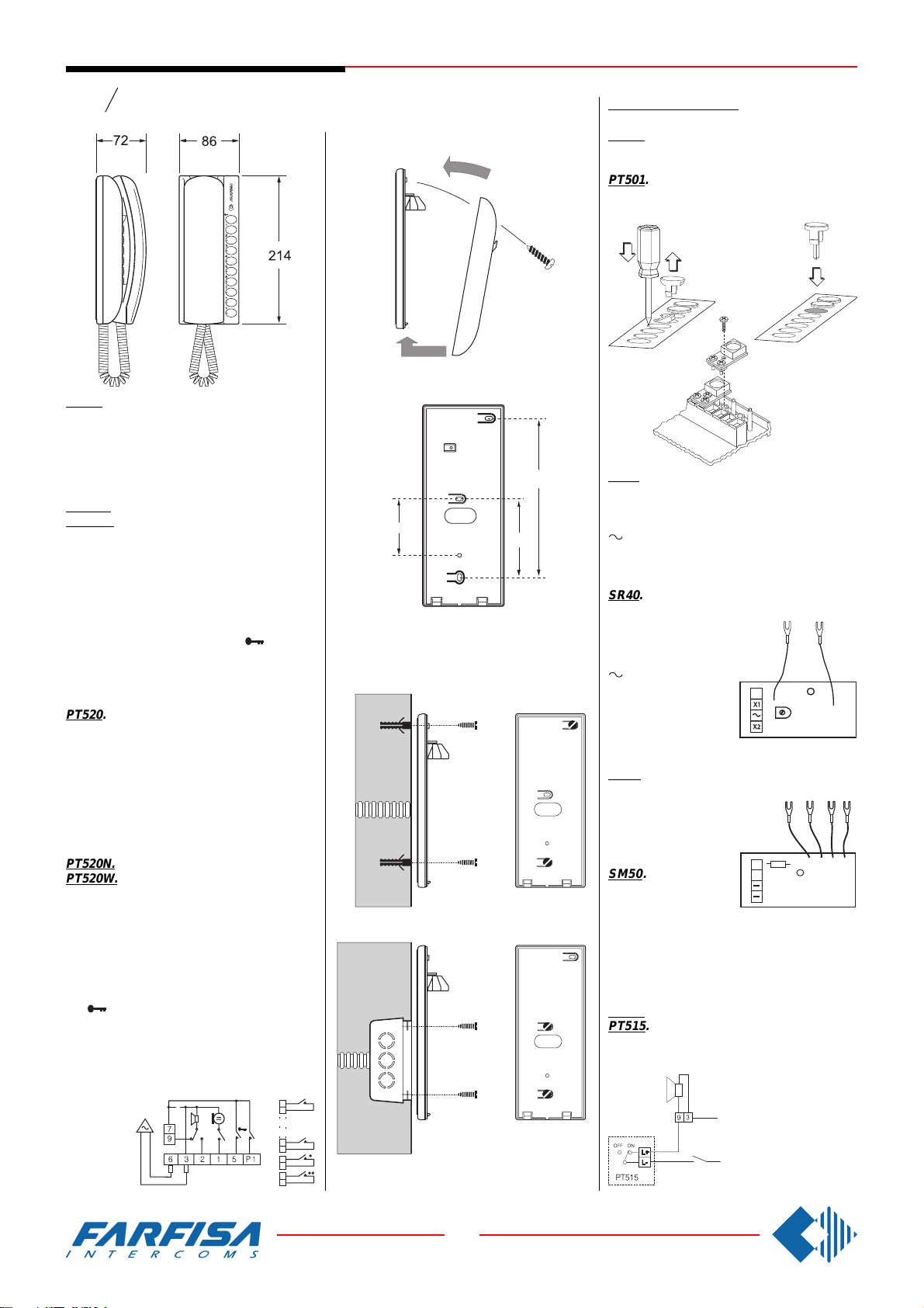
PT520. Two-colour intercom for 4+1 systems
connected to one or more door stations. Complete with buzzer, spiral cord, electronic microphone and two push-buttons that can be increased to 10 by adding the individual pushbutton unit, art.PT501. It can be installed on
the wall with screws or on a back box.
PT520N. Colour: beige.
PT520W. Colour: white.
Terminals
1 microphone
2 loudspeaker
3 ground
5 door release push-button (max 1A)
6 buzzer (absorption 0.2A)
7 common push-buttons ( and 1)
9 electronic bell input
P1 service push-button (max 1A)
P2 ÷ P9 service push-buttons (max 0.5A)
PT520. Haustelefon Farbe schwarz/grau für
4+n Sprechanlagen mit eine oder mehreren
Türstationen. Mit Summer, Spiralkabel, elektronischem Mikrofon und 2 Tasten. Die Tasten
können einzeln bis zu 10 mit Hilfe des Einzeltastenbausatzes Art. Nr. PT501 erweitert werden. Als Tischapparat verwendbar mit Hilfe
des Adapters Art.Nr.PT538. Aufputz Wandmontage. Es können maximal ein Zusatzmodul
Art. Nr.SR40 oder SM50 eingebaut werden.
PT520N. Wie oben aber Farbe beige.
PT520W. Wie oben aber Farbe weiß.
Anschlußklemmen
1 Mikrofon
2 Lautsprecher
3 Masse
5 Taste Türöffner (max. 1A)
6 Summer (Stromverbrauch 0,2A)
7 Gemeinsamer Eingang für Taste Türöffner
und 1
9 Eingang elektronischer Rufton
P1 Funktionstaste (max. 1A)
P2÷P9 Funktionstasten (max. 0,5A)
60
83
167
Fittings /
Zubehör
PT501. Individual push-button unit for PT520,
PT520N and PT520W intercoms.
PT501. Einzeltastenbausatz für Haustelefone
PT520, PT520N und PT520W.
SR40. Electronic bell module (see intercom-
munication diagrams).
Terminals
power supply call input (12Vac-0.5A)
X1 power supply input (12Vac-0.3A)
X2 call input (ground control)
SR40. Zusatzmodul elektronischer Klangruf
(siehe auch Schaltpläne für
Gegensprechanlagen).
Anschlußklemmen
Eingang Wechselstromruf (12Vac/0,5A)
X1 Eingang Wechselstromversorgung
9
7
-
+
(12Vac/0,3A)
X2 Eingang Gleichstromruf (Erdsignal)
SM50. Private conversation module (pag.30)
Terminals
C audio line receiver
B audio line transmitter
- ground
SM50. Zusatzmodul
Mithörsperre (siehe
auch Seite 30).
10K
R1
2136
SM 50
C
B
Anschlußklemmen
C Eingang Sprechweg
B Ausgang Sprechweg
-
Masse
PT515. Bell silencer module (privacy).
PT515. Zusatzmodul Schalter für Rufab-
schaltung (nicht stören) oder andere Sonderfunktionen.
2
W1
P2
1
7
P7
P8
P9
Haustelefon
call push-button
Ruftasten
2
8 GbD-'02
intercom
Page 5
INTERCOMS /
2136
2916357
C
B
9
X2
7
X1
9
9 7
2315P16
X2
7
X1
9
77.572
214
HAUSTELEFONE
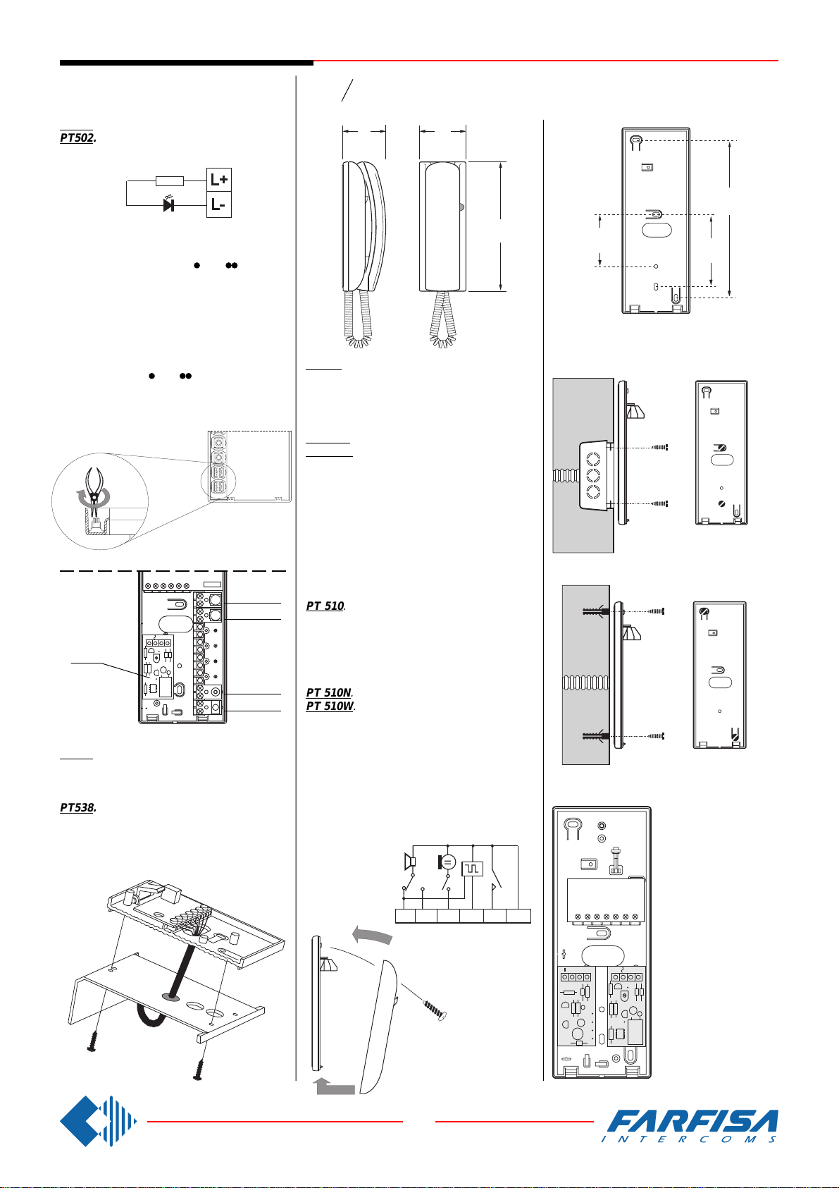
PT502. Led module to indicate door-open.
PT502. Zusatzmodul LED für Türöffnungs-
anzeige oder andere Sonderfunktionen.
Note
We recommend to insert the LED module
PT502 and bell silencer module PT515 in the
bottom 2 seats marked by
and .
To insert them properly it's necessary to remove the guide of the button sliding from the
internal side of the base cover (see figure).
Bitte beachten
Wir empfehlen den Einbau des LED Moduls
PT502 und des Schalter Moduls PT515 in den
zwei letzteren mit und gekennzeichneten
Einbaupositionen. Für den korrekten Einbau
müssen Sie die Tastenführungen auf dem
Gehäuseboden entfernen (siehe Bild).
Series
Serie
Project
PT 510. Two-colour intercom for 4+1 systems
connected to one or more door stations. Complete with push-button, spiral cord, buzzer,
electronic microphone. Wall-mounted with
screws or fixed to back box.
PT 510N. Colour: beige.
PT 510W. Colour: white.
Terminals
1 microphone
2 loudspeaker
3 ground
5 door release push-button (max 1A)
6 buzzer (absorption 0.2A)
9 electronic bell input
60
182
83
PT501
PT501
SR40
or /
oder
SM50
PT502
PT515
PT538. Table adaptor complete with ballast
base, connector, 13 wires cable. For Project
intercom series.
PT538. Tischadapter komplett mit beschwerter Basis, Wandanschlussdose und Verbindungskabel mit 13 Adern für max. 5 Funktionstasten. Für alle Haustelefone Serie Project.
PT 510. Haustelefon Farbe schwarz/grau für
4+n Sprechanlagen mit eine oder mehreren
Türstationen. Mit einer Taste, Spiralschnur,
Summer und elektronischem Mikrofon. Aufputz
Wandmontage. Als Tischapparat verwendbar
mit Hilfe des Adapters Art.Nr.PT538.
PT 510N. Wie oben aber Farbe sandbeige.
PT 510W. Wie oben aber Farbe weiß.
Anschlußklemmen
1 Mikrofon
2 Lautsprecher
3 Masse
5 Taste Türöffner (max. 1A)
6 Summer (Stromverbrauch 0,2A)
9 Eingang elektronischer Rufton
921653
Inside the intercom it can
be added both SM50
(privacy module) and
SR40 (electronic bell
module).
Im Haustelefon können
gleichzeitig beide Zusatzmodule SM50 und
SR40 eingebaut werden.
3
8 GbD-'02
Page 6
INTERCOMS /
HAUSTELEFONE
Series
Serie
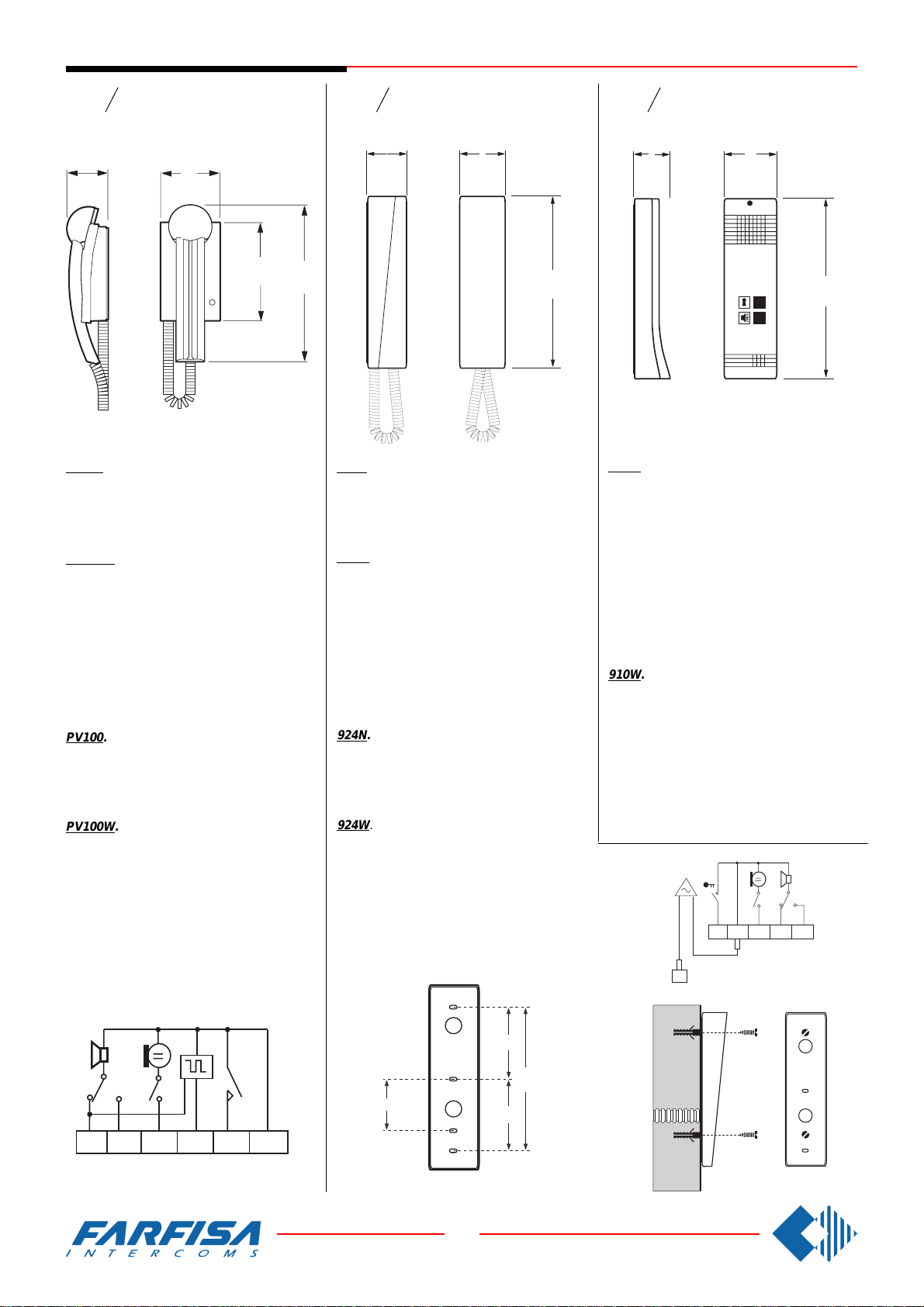
PV100. Two-colour intercom for 4+1 systems
connected to one or more door stations. Complete with push-button, spiral cord, built-in electronic bell, electronic microphone. Wallmounted with screws or fixed to back box.
PV100W. Colour: white.
Terminals
1 Microphone
2 Loudspeaker
3 Ground
5 Door release push-button (1A max)
6 Buzzer (0.35A absorption)
9 Electronic bell input
PV100. Haustelefon Farbe schwarz/grau für
4+n Sprechanlagen mit eine oder mehreren
Türstationen. Mit elektronischem Tonruf, einer
Taste, Spiralkabel und elektronischem Mikrofon. Aufputz Wandmontage.
PV100W. Wie oben aber Farbe weiß.
PuntoVirgola
53
78
128
205
Series
Serie
900 Slim
48
60
225
924N. Beige intercom for 4+1 systems connected to 1 or more door stations. Complete
with a push-button, spiral cord, electronic microphone, buzzer. It can be installed on the
wall with screws.
924W. Colour: white.
Terminals
1 Microphone
2 Loudspeaker
3 Ground
5 Door release push-button (1A max)
6 Buzzer (0.2A absorption)
9 Electronic bell input (from PRS240 or dig-
ital systems)
924N. Haustelefon Farbe sandbeige für 4+n
Sprechanlagen mit eine oder mehreren Türstationen. Mit Summer, einer Taste, Spiralkabel und elektronischem Mikrofon. Aufputz
Wandmontage.
924W. Wie oben aber Farbe weiß.
Series Open voice
Serie
46
900
Freisprech-Haustelefon
66
225
910W. Open-voice, white, two-way model for
4+1 systems connected to one or more door
stations, with internal amplification and modulated electronic bell and knob for adjusting the
volume (receiving channel). This model is provided with two push-buttons (one for connecting the audio line and the other one for the
electric door lock). It can be installed on the
wall with screws or on a wall box.
Terminals
The same of 924 series.
910W. Freisprech-Haustelefon Farbe weiß für
4+n Sprechanlagen mit eine oder mehreren
Türstationen. Mit Gegensprechbetrieb, eingebauten Verstärker, elektronischer Tonruf,
Lautstärkeneinstellung für Lautsprecher und 2
Tasten (eine Sprechwegeinschaltung und die
andere für die Türöffnung). Aufputz Wandmontage.
Anschlußklemmen
Wie Haustelefon Serie 900.
Anschlußklemmen
1 Mikrofon
2 Lautsprecher
3 Masse
5 Taste Türöffner (max. 1A)
6 Summer (Stromverbrauch 0,35A)
9 Eingang elektronischer Rufton
921653
Anschlußklemmen
1 Mikrofon
2 Lautsprecher
3 Masse
5 Taste Türöffner (max. 1A)
6 Summer (Stromverbrauch 0,2A)
9 Eingang elektronischer Rufton (aus Netz-
gerät PRS240 oder mit Digital System)
83
166
60
83
4
8 GbD-'02
2
1
3
5
6
9
Page 7
TELECOMMUNICATION
TELEFONANLAGEN
Electronic PABX's
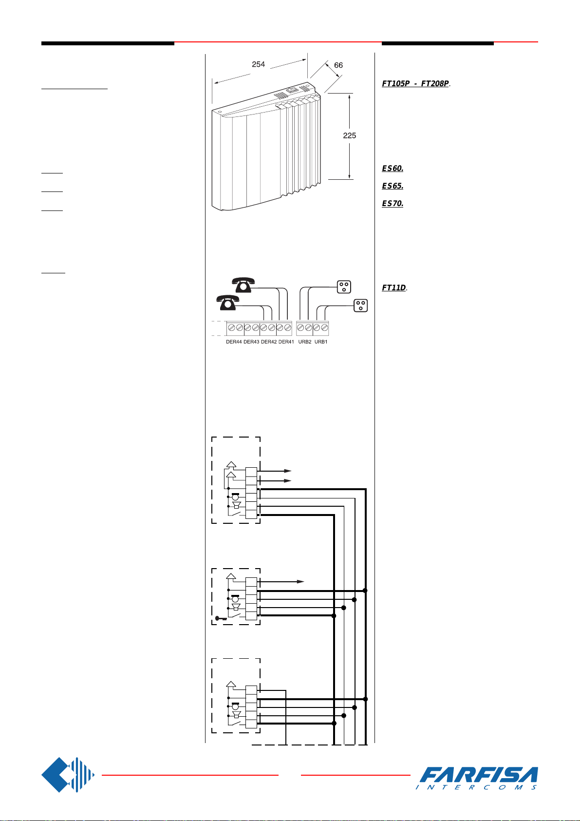
FT105P - FT208P. Electronic PABX with,
respectively, 1 trunk line/5 internal lines and 2
trunk lines/8 internal lines.
Technical data
Power supply: 230V (+6 ÷ -10%)
Maximum power consumption: 18W
Power consumption in stand-by: 10 W
Intercom interface board
ES60. With 2 intercom calls and 2 relays for
lock release or other services.
ES65. With 2 intercom calls and 4 relays for
lock release or other services.
ES70. Board which allows to identify the calling number providing that this service is required to the local telephone provider.
TELEPHONE-INTERFACE INTERCOM
FT11D. It allows the connection of the trunk
line and of the intercom system to hometelephone.
Technical data
Power supply: 127/230V (±10%)
Maximum power consumption: 7VA
Housing: DIN 8 modules A
CONNECTION TO INTERCOM SYSTEM
Intercom interface boards ES60, ES65 and
item FT11D have the same terminal codes and
the same functions as a Farfisa Intercom, they
can be connected to an intercom system 4+1
or standard video-intercom systems (6 wires +
1 + coaxial cable) with one or more door
stations.
Terminals
1 audio transmission
2 audio receiver
3 ground
4 terminal connected to ground. It can be
isolated by cutting W1 jumper (W5 for
FT11D). The relay contact, normally open,
is connected between terminals 4 and 5.
5 lock release (max 1A)
6a intercom call n.1
* 6b intercom call n.2
* 7 relay contact normally closed
* only ES60 and ES65.
CABLE CROSS SECTIONS
In order to connect telephones and trunk lines,
use a telephone wire. The maximum distance
between PABX and the farthest telephone is
350m with a 0.6mm2 pair.
In order to connect the board to the intercom
system, see the cable cross sections (table,
page 18).
FT105P
FT208P
trunk lines
Amtsleitungen
Installation of FT105P, FT208P and FT11D
to an intercom systems.
Einsatz der Telefonanlage und der Wechselsprech-/Telefon-Schnittstelle in einer Haussprechanlage.
ES 60
ES 65
6b
6a
3
1
2
5
Intercom
Haustelefon
6
3
1
2
5
xn
x2
x1
FT 11D
Telefonzentralen
FT105P - FT208P. Telefonanlagen mit, 1
Amtsleitung / 5 Nebenstellen bzw. 2 Amtsleitungen / 8 Nebenstellen.
Technische Daten
Stromversorgung: 230V (±10%)
Max. Leistung: 18W
Min. Leistung: 10W
Erweiterungsbaugruppen
ES60.Schnittstelle Türsprecheinrichtung (4+n)
mit 2 Klingeleingängen und 2 Steuerkontakten.
ES65.Schnittstelle Türsprecheinrichtung (4+n)
mit 2 Klingeleingängen und 4 Steuerkontakten.
ES70. Karte zur Identifizierung der Anrufers,
dessen Nummer nur dann angezeigt wird, wenn
die Aktivierung beim Telefonnetzbetreiber beantragt wurde.
Universalschnittstelle für Türsprechanlage/Telefon
FT11D. An dieser Schnittstelle kann eine
Amtsleitung eine Türsprechstelle mit dem Telefon verbunden werden.
Technische Daten
Stromversorgung: 127/230 V (±10%)
Max. Leistung: 7VA
Gehäuse: DlN 8 Module A
ANSCHLUß AN EINE TÜRSPRECHANLAGE
Die Baugruppen ES60, ES65 und die Universalschnittstelle FT11D haben die selben
Anschlussklemmen und Funktionen wie ein
normales Farfisa Haustelefon. Sie können an
4+n Türsprechanlagen oder Videosprechanlagen (6+n+Koaxialkabel) angeschlossen werden. Ein Betrieb mit mehreren Türstationen ist
möglich.
Anschlußklemmen
1 Audio zur Außenstelle (Senden)
2 Audio von der Außenstelle (Empfang)
3 Masse
4 Masseklemme; die Verbindung kann durch
Trennen der Brücke W1 (W5 für FT11D)
unterbrochen werden. Zwischen den
Klemmen 4 und 5 liegt der n/o Relais
Kontakt
5 Türöffnung (max 1A)
6a Rufanschluß Nr.1
*
6b Rufanschluß Nr.2
*
7 n/c Relaiskontakt
* nur ES60 und ES65.
KABELQUERSCHNlTTE
Telefone und Amtsleitungen werden mittels
entsprenden Dosen angeschlossen. Die max.
Entfernung zwischen TK-Anlage und Nebenstelle beträgt max.350m mit einer 0.6mm²
(Ø1mm) Kabel. Für den Anschluß der Türsprechanlage siehe Tabelle auf Seite 18.
6
3
1
2
5
5
8 GbD-'02
Page 8
PUSH-BUTTON PANELS /
TÜRSTATIONEN
Series
Serie
Mody
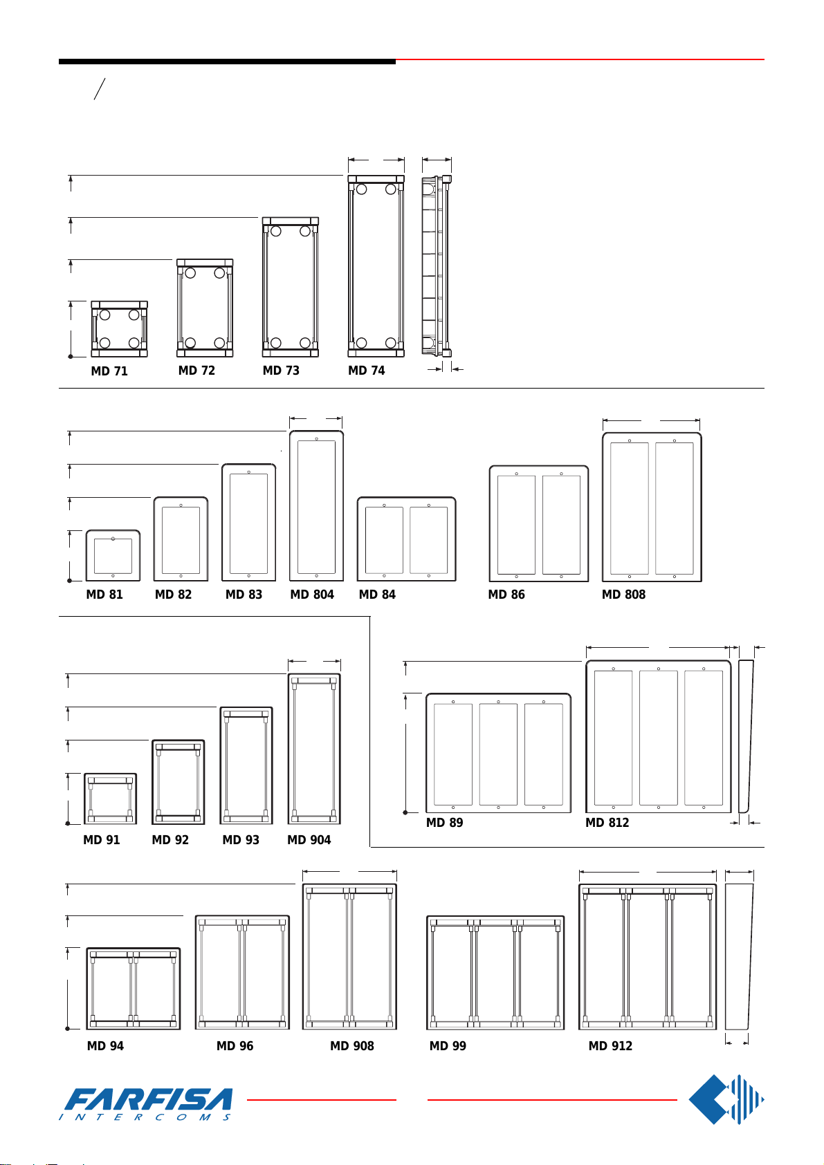
Module frames complete with back box
Unterputzgehäuse mit Modulträgerrahmen
395
304.5
213
121.5
MD 71
Hood covers -
414.5
MD 72 MD 73
Wasserschutzrahmen
151
124
MD 74
Push-button panel in aluminium composed of
modular elements, able to match all installa-
64
tion requirements. Back boxes, module frames,
electric door speaker (amplifier), camera, rain
shelter and various button modules are the
basic elements in this push-button panel line.
Türstationen aus eloxiertem Aluminium, bestehend aus modularen Einheiten. Dies ermöglicht die unterschiedlichsten Installationsvarianten. Unterputz- und Aufputzgehäuse mit
Modulträgerrahmen, Türfreisprecheinrichtung,
Videokamera, Wasserschutzrahmen und verschiedene Ruftastenmodule stellen die Grundelemente dieser modularen Türsprechstation
dar.
19
276
323
231.5
140
MD 81 MD 82 MD 83 MD 804 MD 84 MD 86 MD 808
Rain shelter with module frames -
mit Modulträgerrahmen und Wasserschutz
414.5
323
231.5
140
Aufputzgehäuse
151
414.5
323
MD 91 MD 92 MD 93 MD 904
276
401
MD 812MD 89
401
40
25
80
414.5
323
231.5
MD 94 MD 96 MD 908
6
8 GbD-'02
MD 912MD 99
65
Page 9
PUSH-BUTTON PANELS /
8 7 6 5 4 3 2 1
12Vca
12Vcc
45
124
90
19
1
7
A
4
2
8
5
0
3
9
B
6
TÜRSTATIONEN
Series
Serie
1 row push-button modules -
Mody
Tastenmodule (Einfach)
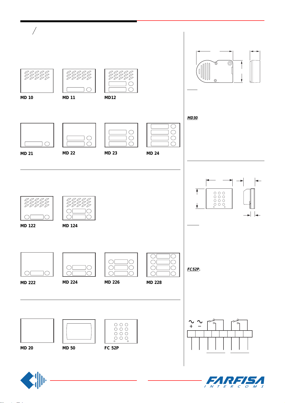
Modules for electric door speaker (amplifier)
Module für Türlautsprecher
MD 10
without call buttons
Ohne Ruftasten
Button modules -
MD 21
1call button
Mit 1 Ruftaste
2 row push-button modules -
MD 11
1call button
Mit 1 Ruftaste
Ruftastenmodule
MD 22
2 call buttons
Mit 2 Ruftasten
Tastenmodule (Doppelt)
MD12
2 call buttons
Mit 2 Ruftasten
MD 23
3 call buttons
Mit 3 Ruftasten
MD 24
4 call buttons
Mit 4 Ruftasten
ELECTRIC DOOR SPEAKER (amplifier)
TÜRFREISPRECHEINRICHTUNG 4+n
Sprechanlagen
91
MD30. It consists of a double amplifier; transmitter and receiver with adjustable volume.
Terminals
1 receiver 2 transmitter
3 power supply 6÷8Vdc 4 ground
MD30. Besteht aus einem zweifachen Verstär-
ker (Empfang- und Senderichtung) mit
Lautstärkeregelung für Lautsprecher und Mikrofon.
Anschlußklemmen
1 Sprechweg Empfangrichtung
2 Sprechweg Senderichtung
3 Gleichstromversorgung +6÷8 Vdc
4 Masse
25.5
55
ACCESS CONTROL KEYPAD
CODESCHLOßMODUL
Modules for electric door speaker (amplifier)
Module für Türlautsprecher
MD 122
2 call buttons
Mit 2 Ruftasten
Button modules -
MD 222
2 call buttons
Mit 2 Ruftasten
MD 124
4 call buttons
Mit 4 Ruftasten
Ruftastenmodule
MD 224
4 call buttons
Mit 4 Ruftasten
MD 226
6 call buttons
Mit 6 Ruftasten
Blank, number and access control modules
Leermodul, Informationsmodul und Codeschloßmodul
2
3
1
5
6
4
8
9
50
7
B
A
0
MD 228
8 call buttons
Mit 8 Ruftasten
FC52P. Access control keypad with 12 digits
and 2 relays for lock release. 4 programmable
access codes for each relay. Programmable
door opening time from 1 up 99 sec. for each
relay (or bistable operation of one relay). Acoustic confirmation for entered keys, accepted
program-mation and for wrong codes.
Power supply: 13VAC/DC-0.1A.
Contact rating: 12VAC-5A.
FC52P. Elektronische Tastatur mit 12 Tasten
und 2 Relais für die Zutrittskontrolle.
4 programmierbare Codes pro Relais.
Programmierbare Öffnungszeit von 1 bis 99
Sekunden pro Relais oder bistabiler Betrieb
des Relais 1. Akustische und visuelle Anzeige
bei Tastendruck, falscher Eingabe und Programmierung.
Stromversongung: 13Vca/cc-0,1A.
Max. Belastung: 12Vca-5A.
87654321
MD 20
blank module
Leermodul
MD 50
number module
Informationsmodul
FC 52P
access control keypad
Codeschloßmodul für Zutrittskontrolle.
7
8 GbD-'02
12Vca
13Vac
12Vcc
13Vdc
Relay 1 Relay 2
Relè 1
Relais 1 Relais 2
Relè 2
Page 10
PUSH-BUTTON PANELS /
TÜRSTATIONEN
Series
Serie
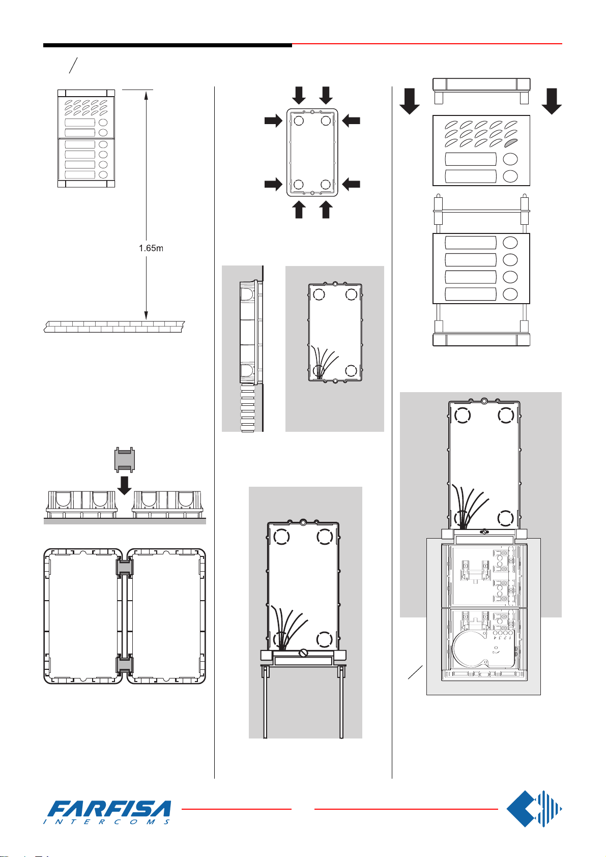
Recommended height of panel installation.
Empfohlene Einbauhöhe
Mody
.
Openings for cables.
Positionen der Kabeldurchführungen.
Mounting of button module.
Installation der Module.
Insertion of cable bush between back boxes.
The cable bushes must be inserted before
brickwork.
Einbau der Verbindungselemente mit Kabeldurchführung zwischen den Unterputzgehäusen. Die Verbindungselemente müssen
vor den Einbau installiert werden.
Flush mounting and cables placing.
Unterputzeinbau und Kabelzufuhr.
Mounting the frame bottom.
Untere Befestigung des Modulträgerrahmens.
(a)
Lower fixing of the module frame on back box.
It is advised to insert a protection (a) between
panel and wall while mounting.
Während der Verkabelung der Module ist der
Einsatz eines Schutzes (a) zwischen Modulen
und Mauer empfohlen.
8
8 GbD-'02
Page 11
PUSH-BUTTON PANELS /
TÜRSTATIONEN
Series
Serie
Mody
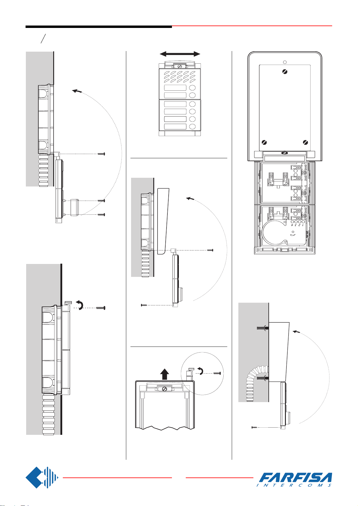
Alignment of the panel.
Ausrichtung der Türstation.
Hood covers
Wasserschutzrahmen
Fixing of frame bottom side and door speaker
mounting.
Untere Befestigung des Modulträgerrahmens
Befestigung der Türfreisprecheinrichtung.
Modules insertion and wall mounting of rain
shelter.
Einbau der Module auf dem Modulträgerrahmen
und Wandbefestigung des Aufputzgehäuses.
Mounting of the hood cover between the back
box and the module frame.
Installation eines Wasserschutzrahmens zwischen Modulträgerrahmen und Unterputzgehäuse.
Rain shelter
Aufputzgehäuse
Top fixing of the panel.
Obere Befestigung des Modulträgerrahmens.
Dismounting of the frame from the rain shelter.
Öffnung des Modulträgerrahmens durch Entfernung der oberen Befestigungsschraube.
9
8 GbD-'02
Mounting of the frame top to the rain shelter.
Schließung des Modulträgerrahmens und Befestigung mit der oberen Schraube.
Page 12
PUSH-BUTTON PANELS /
TÜRSTATIONEN
Series
Serie
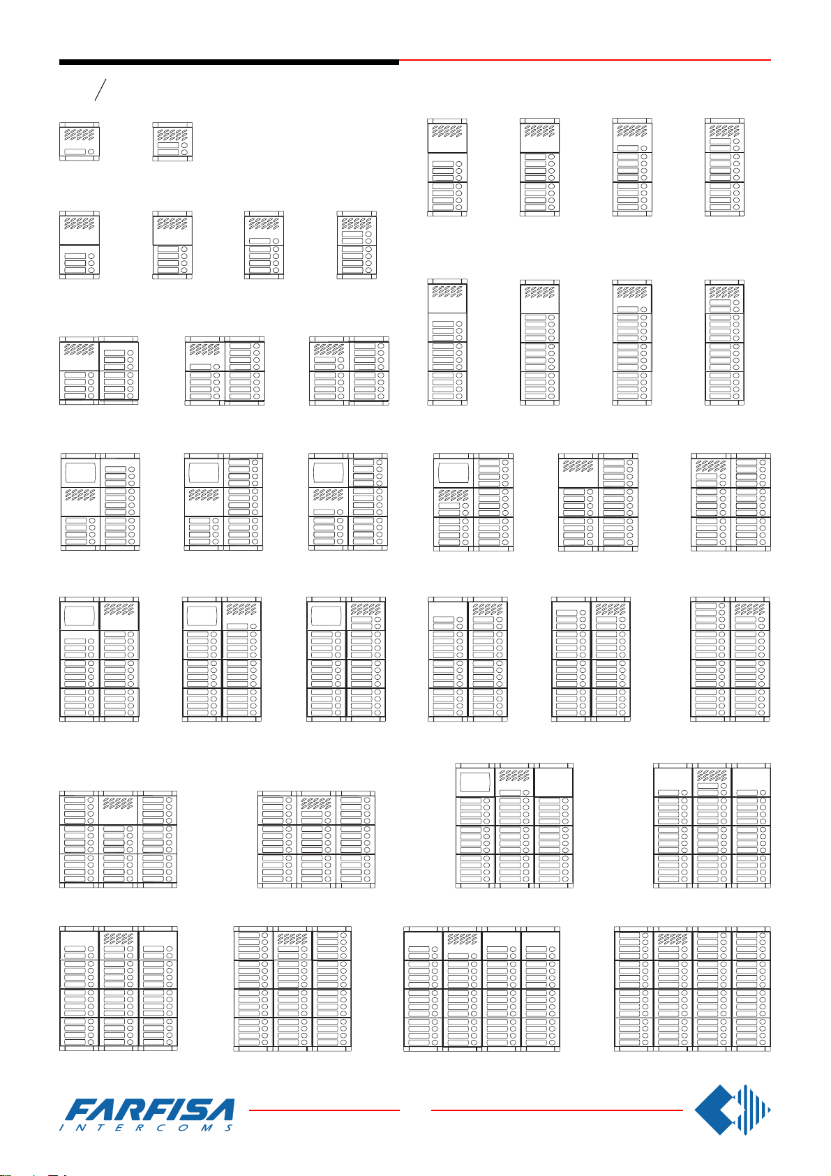
1 call button
1 Taste
- 1 row push-buttons
3 call buttons
3 Tasten
Mody
2 call buttons
2 Tasten
4 call buttons
4 Tasten
Einzeltasten
11 call buttons
11 Tasten
21 21
13 call buttons
13 Tasten
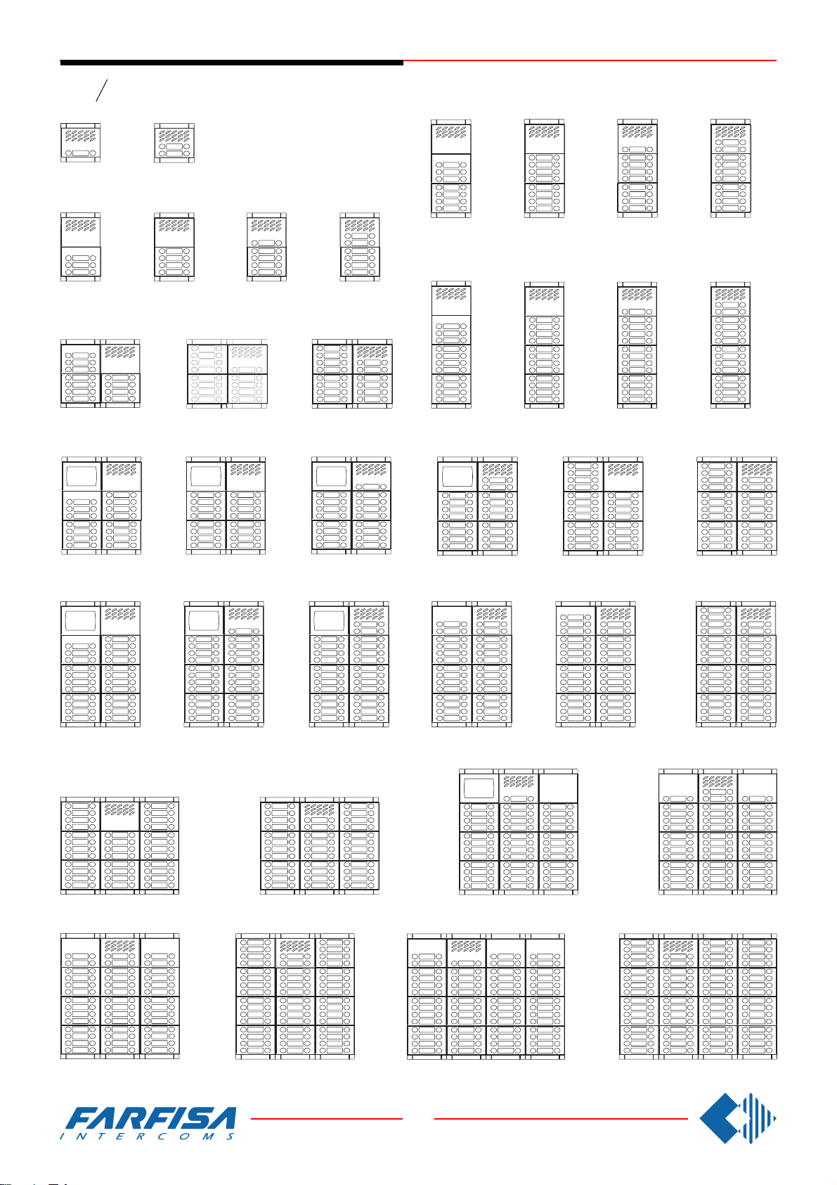
Examples of Mody push-button panel installations.
Beispiele für die Zusammensetzung von MODY Türstationen bei Sprechanlagen.
5 call buttons
5 Tasten
6 call buttons
6 Tasten
14 call buttons
14 Tasten
21
7 call buttons
7 Tasten
11 call buttons
11 Tasten
21
8 call buttons
8 Tasten
12 call buttons
12 Tasten
9 call buttons
9 Tasten
13 call buttons
13 Tasten
10 call buttons
10 Tasten
14 call buttons
14 Tasten
15 call buttons
15 Tasten
21 2121
23 call buttons
23 Tasten
32 call buttons
32 Tasten
25 call buttons
25 Tasten
16 call buttons
16 Tasten
17 call buttons
17 Tasten
26 call buttons
26 Tasten
34 call buttons
34 Tasten
18 call buttons
18 Tasten
28 call buttons
28 Tasten
21
37 call buttons
37 Tasten
20 call buttons
20 Tasten
29 call buttons
29 Tasten
22 call buttons
22 Tasten
30 call buttons
30 Tasten
40 call buttons
40 Tasten
42 call buttons
42 Tasten
46 call buttons
46 Tasten
55 call buttons
55 Tasten
10
8 GbD-'02
62 call buttons
62 Tasten
Page 13
PUSH-BUTTON PANELS /
TÜRSTATIONEN
Series
Serie
Tasten
Mody
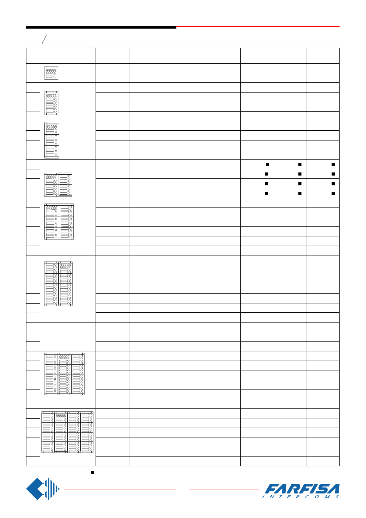
Compositions and dimensions
N°
calls
Ansicht und Maße
1
2
3
4
5
6
7
8
9
10
11
12
13
14
15
16
17
18
20
22
248x304,5x19
(L x H x P)
23
24
25
27
28
29
30
248x395x19
(L x H x P)
31
32
34
372x304,5x19
(L x H x P)
(L x H x B)
35
37
40
42
43
46
372x395x19
(L x H x P)
48
50
53
55
58
62
496x395x19
(L x H x P)
124x121,5x19
(L x H x P)
(L x H x B)
124x213x19
(L x H x P)
(L x H x B)
124x304,5x19
(L x H x P)
(L x H x B)
248x213x19
(L x H x P)
(L x H x B)
(L x H x B)
(L x H x B)
(L x H x B)
(L x H x B)
Door speaker
Türfreisprechein-
richtung
1 MD30
1 MD30
1 MD30
1 MD30
1 MD30
1 MD30
1 MD30
1 MD30
1 MD30
1 MD30
1 MD30
1 MD30
1 MD30
1 MD30
1 MD30
1 MD30
1 MD30
1 MD30
1 MD30
1 MD30
1 MD30
1 MD30
1 MD30
1 MD30
1 MD30
1 MD30
1 MD30
1 MD30
1 MD30
1 MD30
1 MD30
1 MD30
1 MD30
1 MD30
1 MD30
1 MD30
1 MD30
1 MD30
1 MD30
1 MD30
1 MD30
1 MD30
or/
oder
MD74 or/
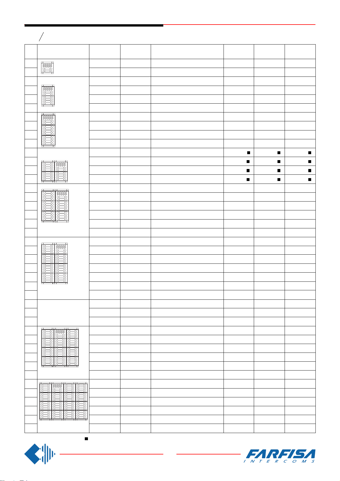
Composition board of Mody push-button panels in intercom installations.
Tabelle zur Konfiguration von MODY Türstationen bei 4+n Sprechanlagen.
Mod. for speaker
Türsprechmodul
1 MD11
1 MD12
1 MD10
1 MD10
1 MD11
1 MD12
1 MD10
1 MD10
1 MD11
1 MD12
1 MD10
1 MD10
1 MD11
1 MD12
1 MD10
1 MD10
1 MD11
1 MD12
1 MD12
1 MD12
1 MD10
1 MD10
1 MD11
1 MD12
1 MD12
1 MD12
1 MD12
1 MD12
1 MD10
1 MD12
1 MD10
1 MD11
1 MD12
1 MD12
1 MD12
1 MD12
1 MD10
1 MD10
1 MD11
1 MD11
1 MD11
1 MD12
oder
MD804 or/
Button modules and info or blank module
Ruftasten-, Info- und Leermodul
-
1 MD23
1 MD24
1 MD24
1 MD24
1 MD24
2 MD24
2 MD24
2 MD24
2 MD24
3 MD24
3 MD24
3 MD24
3 MD24
4 MD24
4 MD24
4 MD24
4 MD24
5 MD24
5 MD24
6 MD24
6 MD24
6 MD24
6 MD24
6 MD24
7 MD24
7 MD24
8 MD24
8 MD24
8 MD24
9 MD24
9 MD24
9 MD24
10 MD24
11 MD24
12 MD24
12 MD24
12 MD24
12 MD24
12 MD24
15 MD24
oder
MD904
-
-
-
-
-
-
1 MD23
-
-
-
1 MD23
-
-
-
1 MD23
-
-
-
1 MD22
-
1 MD23
-
1 MD21
1 MD22
1 MD23
1 MD21
-
1 MD23
2 MD21
2 MD22
1 MD21
-
2 MD21
2 MD22
3 MD22
3 MD23
-
* or MD50 /
-
-
-
-
-
-
-
-
-
-
-
-
-
1 MD20 *
1 MD20 *
1 MD20 *
1 MD20 *
-
1 MD20 *
1 MD20 *
1 MD20 *
-
-
-
-
-
-
2 MD20 *
2 MD20 *
-
-
-
3 MD20 *
1 MD20 *
1 MD20 *
-
-
-
Back box
Unterputz-
gehäuse
1 MD71
1 MD71
1 MD72
1 MD72
1 MD72
1 MD72
1 MD73
1 MD73
1 MD73
1 MD73
2 MD72
2 MD72
2 MD72
2 MD72
2 MD73
2 MD73
2 MD73
2 MD73
2 MD73
2 MD73
2 MD74
2 MD74
2 MD74
2 MD74
2 MD74
2 MD74
2 MD74
3 MD73
3 MD73
3 MD73
3 MD74
3 MD74
3 MD74
3 MD74
3 MD74
3 MD74
4 MD74
4 MD74
4 MD74
4 MD74
4 MD74
4 MD74
oder MD50
Hood covers
Wasserschutz
1 MD81
1 MD81
1 MD82
1 MD82
1 MD82
1 MD82
1 MD83
1 MD83
1 MD83
1 MD83
1 MD84
1 MD84
1 MD84
1 MD84
1 MD86
1 MD86
1 MD86
1 MD86
1 MD86
1 MD86
1 MD808
1 MD808
1 MD808
1 MD808
1 MD808
1 MD808
1 MD808
1 MD89
1 MD89
1 MD89
1 MD812
1 MD812
1 MD812
1 MD812
1 MD812
1 MD812
-
-
-
-
-
-
Rain shelter
Aufputzgehäuse
1 MD91
1 MD91
1 MD92
1 MD92
1 MD92
1 MD92
1 MD93
1 MD93
1 MD93
1 MD93
1 MD94
1 MD94
1 MD94
1 MD94
1 MD96
1 MD96
1 MD96
1 MD96
1 MD96
1 MD96
1 MD904
1 MD904
1 MD904
1 MD904
1 MD904
1 MD904
1 MD904
1 MD99
1 MD99
1 MD99
1 MD912
1 MD912
1 MD912
1 MD912
1 MD912
1 MD912
-
-
-
-
-
-
- 1 row push-buttons
Einzeltasten
11
8 GbD-'02
Page 14
PUSH-BUTTON PANELS /
TÜRSTATIONEN
Series
Serie
2 call buttons
2 Tasten
- 2 row push-buttons
6 call buttons
6 Tasten
Mody
4 call buttons
4 Tasten
8 call buttons
8 Tasten
Doppeltasten
22 call buttons
22 Tasten
21 21
26 call buttons
26 Tasten
Examples of Mody push-button panel installations.
Beispiele für die Zusammensetzung von MODY Türstationen bei Sprechanlagen.
10 call buttons
10 Tasten
12 call buttons
12 Tasten
28 call buttons
28 Tasten
21
14 call buttons
14 Tasten
22 call buttons
22 Tasten
21
16 call buttons
16 Tasten
24 call buttons
24 Tasten
18 call buttons
18 Tasten
26 call buttons
26 Tasten
20 call buttons
20 Tasten
28 call buttons
28 Tasten
30 call buttons
30 Tasten
21 2121
46 call buttons
46 Tasten
64 call buttons
64 Tasten
50 call buttons
50 Tasten
32 call buttons
32 Tasten
34 call buttons
34 Tasten
52 call buttons
52 Tasten
68 call buttons
68 Tasten
36 call buttons
36 Tasten
56 call buttons
56 Tasten
21
74 call buttons
74 Tasten
40 call buttons
40 Tasten
58 call buttons
58 Tasten
44 call buttons
44 Tasten
60 call buttons
60 Tasten
80 call buttons
80 Tasten
84 call buttons
84 Tasten
92 call buttons
92 Tasten
110 call buttons
110 Tasten
12
8 GbD-'02
124 call buttons
124 Tasten
Page 15
PUSH-BUTTON PANELS /
TÜRSTATIONEN
Series
Serie
Tasten
Mody
Compositions and dimensions
N°
calls
Ansicht und Maße
2
4
6
8
10
12
14
16
18
20
22
(L x H x P)
24
26
28
30
32
34
36
40
44
248x304,5x19
(L x H x P)
46
48
50
54
56
58
60
248x395x19
(L x H x P)
62
64
372x304,5x19
(L x H x P)
68
70
74
80
84
86
92
372x395x19
(L x H x P)
96
100
106
110
116
124
496x395x19
(L x H x P)
124x121,5x19
(L x H x P)
(L x H x B)
124x213x19
(L x H x P)
(L x H x B)
124x304,5x19
(L x H x P)
(L x H x B)
248x213x19
(L x H x B)
(L x H x B)
(L x H x B)
(L x H x B)
(L x H x B)
(L x H x B)
Door speaker
Türfreisprechein-
richtung
1 MD30
1 MD30
1 MD30
1 MD30
1 MD30
1 MD30
1 MD30
1 MD30
1 MD30
1 MD30
1 MD30
1 MD30
1 MD30
1 MD30
1 MD30
1 MD30
1 MD30
1 MD30
1 MD30
1 MD30
1 MD30
1 MD30
1 MD30
1 MD30
1 MD30
1 MD30
1 MD30
1 MD30
1 MD30
1 MD30
1 MD30
1 MD30
1 MD30
1 MD30
1 MD30
1 MD30
1 MD30
1 MD30
1 MD30
1 MD30
1 MD30
1 MD30
or/
oder
MD74 or/
Composition board of Mody push-button panels in intercom installations.
Tabelle zur Konfiguration von MODY Türstationen bei 4+n Sprechanlagen.
Mod. for speaker
Türsprechmodul
1 MD122
1 MD124
1 MD10
1 MD10
1 MD122
1 MD124
1 MD10
1 MD10
1 MD122
1 MD124
1 MD10
1 MD10
1 MD122
1 MD124
1 MD10
1 MD10
1 MD122
1 MD124
1 MD124
1 MD124
1 MD10
1 MD10
1 MD122
1 MD124
1 MD124
1 MD124
1 MD124
1 MD124
1 MD10
1 MD124
1 MD10
1 MD122
1 MD124
1 MD124
1 MD124
1 MD124
1 MD10
1 MD10
1 MD122
1 MD122
1 MD122
1 MD124
oder
MD804 or/
Button modules and info or blank module
Ruftasten-, Info- und Leermodul
-
1 MD226
1 MD228
1 MD228
1 MD228
1 MD228
2 MD228
2 MD228
2 MD228
2 MD228
3 MD228
3 MD228
3 MD228
3 MD228
4 MD228
4 MD228
4 MD228
4 MD228
5 MD228
5 MD228
6 MD228
6 MD228
6 MD228
6 MD228
6 MD228
7 MD228
7 MD228
8 MD228
8 MD228
8 MD228
9 MD228
9 MD228
9 MD228
10 MD228
11 MD228
12 MD228
12 MD228
12 MD228
12 MD228
12 MD228
15 MD228
oder
MD904
-
-
-
-
-
-
1 MD226
-
-
-
1 MD226
-
-
-
1 MD226
-
-
-
1 MD224
-
1 MD226
-
1 MD222
1 MD224
1 MD226
1 MD222
-
1 MD226
2 MD222
2 MD224
1 MD222
-
2 MD222
2 MD224
3 MD224
3 MD226
-
* or MD50 /
-
-
-
-
-
-
-
-
-
-
-
-
-
1 MD20 *
1 MD20 *
1 MD20 *
1 MD20 *
-
1 MD20 *
1 MD20 *
1 MD20 *
-
-
-
-
-
-
2 MD20 *
2 MD20 *
-
-
-
3 MD20 *
1 MD20 *
1 MD20 *
-
-
-
oder MD50
Back box
Unterputz-
gehäuse
1 MD71
1 MD71
1 MD72
1 MD72
1 MD72
1 MD72
1 MD73
1 MD73
1 MD73
1 MD73
2 MD72
2 MD72
2 MD72
2 MD72
2 MD73
2 MD73
2 MD73
2 MD73
2 MD73
2 MD73
2 MD74
2 MD74
2 MD74
2 MD74
2 MD74
2 MD74
2 MD74
3 MD73
3 MD73
3 MD73
3 MD74
3 MD74
3 MD74
3 MD74
3 MD74
3 MD74
4 MD74
4 MD74
4 MD74
4 MD74
4 MD74
4 MD74
Hood covers
Wasserschutz
1 MD81
1 MD81
1 MD82
1 MD82
1 MD82
1 MD82
1 MD83
1 MD83
1 MD83
1 MD83
1 MD84
1 MD84
1 MD84
1 MD84
1 MD86
1 MD86
1 MD86
1 MD86
1 MD86
1 MD86
1 MD808
1 MD808
1 MD808
1 MD808
1 MD808
1 MD808
1 MD808
1 MD89
1 MD89
1 MD89
1 MD812
1 MD812
1 MD812
1 MD812
1 MD812
1 MD812
-
-
-
-
-
-
Rain shelter
Aufputzgehäuse
1 MD91
1 MD91
1 MD92
1 MD92
1 MD92
1 MD92
1 MD93
1 MD93
1 MD93
1 MD93
1 MD94
1 MD94
1 MD94
1 MD94
1 MD96
1 MD96
1 MD96
1 MD96
1 MD96
1 MD96
1 MD904
1 MD904
1 MD904
1 MD904
1 MD904
1 MD904
1 MD904
1 MD99
1 MD99
1 MD99
1 MD912
1 MD912
1 MD912
1 MD912
1 MD912
1 MD912
-
-
-
-
-
-
- 2 row push-buttons
Doppeltasten
13
8 GbD-'02
Page 16
PUSH-BUTTON PANELS /
TÜRSTATIONEN
Series
Serie
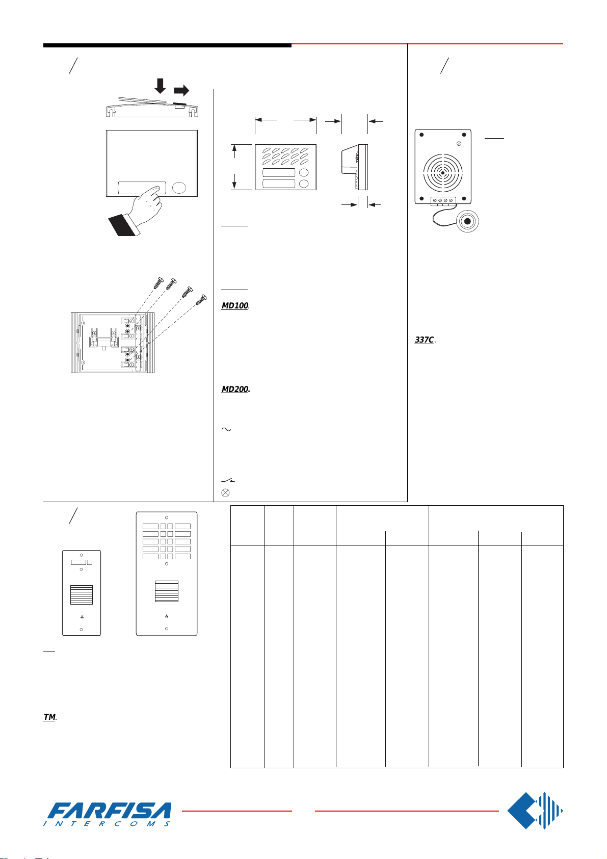
Dismounting of name holder to insert name
label
Öffnung der Namenschildabdeckung zur Beschriftung des Namenschildes.
In any button module, to avoid the dismounting
of name holder a screw 3MAx12 can be inserted in the holes in order to block each label.
Um die unerwünschte Öffnung der Namenschilderabdeckungen von Aussen zu vermeiden können diese mit Hilfe von 3MAx12 Schrauben befestigt werden. Diese werden in den im
Bild gezeigten Löchern eingeschraubt. Je
Namenschildisteine Schraube notwendig. Diese werden nicht vom Hersteller geliefert. Bei
einer 1+n Sprechanlage ist dieses Merkmal
nicht verfügbar.
Mody
AMPLIFIED DOOR STATIONS
MODULE MIT INTEGRIERTEM TÜRLAUTSPRECHER
124
90
MD100. 1 button module. It can be applied to all
4+1 system and intercommunicating systems. It
can replace in many installations module MD11
and MD30, using all the other accessories of the
Mody series (see diagrams on pages 22, 24 and
36).
MD200. 2 button module.
MD100. Modul mit einer Taste. Dieses Modul
kann für alle Türsprechanlagen 4+n und Gegensprechanlagen verwendet werden. Kann in vielen
Installationsversionen anstelle des MD11 und MD30
Moduls eingesetzt werden, wobei alle anderen
Zubehörteile der serie Mody verwendet werden.
Zur Installation des Moduls siehe auch den Schaltplan auf Seite 22, 24 und 36).
MD200. Modul mit zwei Tasten.
Terminals -
- ground -
1 receiver -
2 transmitter -
C call push-buttons common -
name plate lamp -
Anschlußklemmen
supply -
Eingang Ruftasten
call push-buttons -
Masse
Stromversorgung
Sprechweg Empfangrichtung
Sprechweg Senderichtung
Ruftasten
Beleuchtung
52
19
13Vac-60mA
gemeinsamer
(24V-70mA)
Series
Serie
ErreP/R - TM
Electric door-speaker (amplifier)
Türfreisprecheinrichtung
4+n Sprechanlagen
337C. It consists in a
double amplifier (receiver and transmitter); receiver with adjustable volume. It can
be fitted in RP, NP or
1234
Provided with an electret microphone and
tropicalized speaker.
Terminals
1 receiver
2 transmitter
3 positive power supply 6÷8Vdc
4 ground
337C. Besteht aus einem zweifachen Ver-
stärker (Empfang- und Senderichtung) mit
Lautstärkeregelung für den Lautsprecher
und elektronischem Mikrofon. Wird in die
RP und TM Klingelplatten eingebaut. Mit
Hilfe des Adapters Art.Nr. 299 auch in
fremde Türstationen (z.B. Briefkastensysteme) einbaubar.
Anschlußklemmen
1 Sprechweg Empfangrichtung
2 Sprechweg Senderichtung
3 Gleichstromversorgung +6÷8 Vdc
4 Masse
TM push-button pan-
els (or in other pushbutton panels by
means of the adaptor
art.299).
Series
Serie
TM. Push-button panels with square aluminium
push-buttons. Anticorodal front panel, 4mm thick.
Available on 1,2,4 rows of push-buttons. Preset for
the fitting of an electric door-speaker (amplifier).
Lamp holder for name plate illumination. Safety
screws. Depth self-adjustable contact unit.
TM. Türsprechstation mit rechteckigen Ruftasten
aus eloxiertem Aluminium. 4 mm dicke Frontplatte.
Verfügbar mit 1, 2 oder 4 Tastenreihen. Es ist der
Einbau einer Türfreisprecheinrichtung Art.Nr.337C
für 4+n Sprechanlagen, oder Art.Nr.357 für 1+n
Sprechanlagen, möglich. Beleuchtete Namenschilder, Sicherheitsschrauben und einstellbare
Tastenkontakte.
TM
Article Rows
Art. Nr. Reihen Tasten Maße Frontplatte mm Maße Unterputzgehäuse mm
T1M1 1 1 270 123 259 110 65
T1M2 1 2 293 123 282 110 65
T1M3 1 3 316 123 305 110 65
T2M4 2 4 293 180 282 155 65
T2M6 2 6 316 180 305 155 65
T2M8 2 8 339 180 328 155 65
T2M10 2 10 362 180 351 155 65
T2M12 2 12 385 180 374 155 65
T2M14 2 14 408 180 397 155 65
T2M16 2 16 431 180 420 155 65
T2M18 2 18 454 180 443 155 65
T2M20 2 20 477 180 466 155 65
T4M24 4 24 293 340 273 320 65
T4M28 4 28 316 340 296 320 65
T4M32 4 32 339 340 319 320 65
T4M36 4 36 362 340 342 320 65
T4M40 4 40 385 340 365 320 65
T4M44 4 44 408 340 388 320 65
T4M48 4 48 431 340 411 320 65
T4M52 4 52 454 340 434 320 65
T4M60 4 60 500 340 480 320 65
Rain shelters are supplied on request.
Push-button
N° N° Height/
Plate dimension mm Wall box dimension mm
Höhe
Width/
Breite
Height/
Höhe
Width/
Breite
Depth/
/ Auf Anfrage sind auch Aufputzgehäuse lieferbar.
Tiefe
14
8 GbD-'02
Page 17
PUSH-BUTTON PANELS /
L
40 mm
164
122
40
TÜRSTATIONEN
Series
Serie
RP. Modular push-button panels with ano-
dized aluminium front panel and push-buttons. Complete with name plate lamps. Electric-door speaker (amplifier) can be fitted
inside the push-button panel. For installation
in exposed areas, the rain shelter art.290R/
.. should be used.
The unit should be flush-mounted and
the microphone should be firmly attached
to the front panel to avoid feedback and to
obtain the highest audio quality.
Mody
RP12
R14 R12
RP10
RP8
RP6
R. Push-button panels provided only with push-
R10 R8
stationen mit mehr als 12 Klingeltasten.
RP4
RP. Türstationen mit Frontplatte aus eloxiertem Aluminium, Kunststofftasten und Namensschildbeleuchtung. Es ist der Einbau einer Türfreisprecheinrichtung Art.Nr.337C möglich. Aufputzgehäuse mit
wasserschutzrahmen sind unter der Art.Nr.290R/.. lieferbar. Um die beste Klangqualität zu erreichen,
und mögliche Rückkoppeleffekte zu vermeiden,
muß beim Einbau beachtet werden das die Kanten
mit der verputzten Mauer bündig sind. Weiterhin
sollte das Mikrofon mit der Frontplatte genau abschließen.
313
281.5
250
218.5
RP2 RP 1
buttons. An electric door
speaker (amplifier) cannot
be fitted. When such panels
are installed with the RP
series, systems with over
12 calls can be arranged.
R. Klingelplatten nur mit
Tasten. Ohne Einbaumöglichkeit für die Türfreisprecheinrichtung. Kombiniert mit den o.g.RP Tür-
stellen ermöglichen diese
die Herstellung von Tür-
376
313
281.5
250
218.5
RP100. Amplified door
station with 1
push-button.
It can be fitted
in all 4+1 intercom systems and in-
cating systems. Door-speaker with double
amplification and adjustable volume, call
push-button and anodized aluminium front
panel, rain shelter and name plate lamp.
Wall-mounted with screws or on wall box.
RP200. Amplified door station with 2
push-buttons.
Terminals
tercommuni-
- ground
power supply 13VAC - 0.13A
1 receiver
2 transmitter
C common push-buttons
P1-P2 call push-buttons
RP100. Türstation mit eingebauter Freisprecheinrichtung und einer Klingeltaste. Diese kann bei allen Einfamilien-
haus 4+n Anlagen und Gegensprechanlagen eingesetzt werden. Mit Freisprecheinrichtung, Lautstärkeregelung, Ruftaste und
Frontplatte aus eloxiertem Aluminium, Regendach und Namensschildbeleuchtung.
Aufputzmontage.
RP200. Türstation mit 2 Klingeltasten.
Anschlußklemmen
-
Masse
Stromversorgung 13Vac-0,13A
1 Sprechweg Empfangsrichtung
2 Sprechweg Senderichtung
C gemeinsamer Eingang Ruftasten
P1-P2 Ruftasten
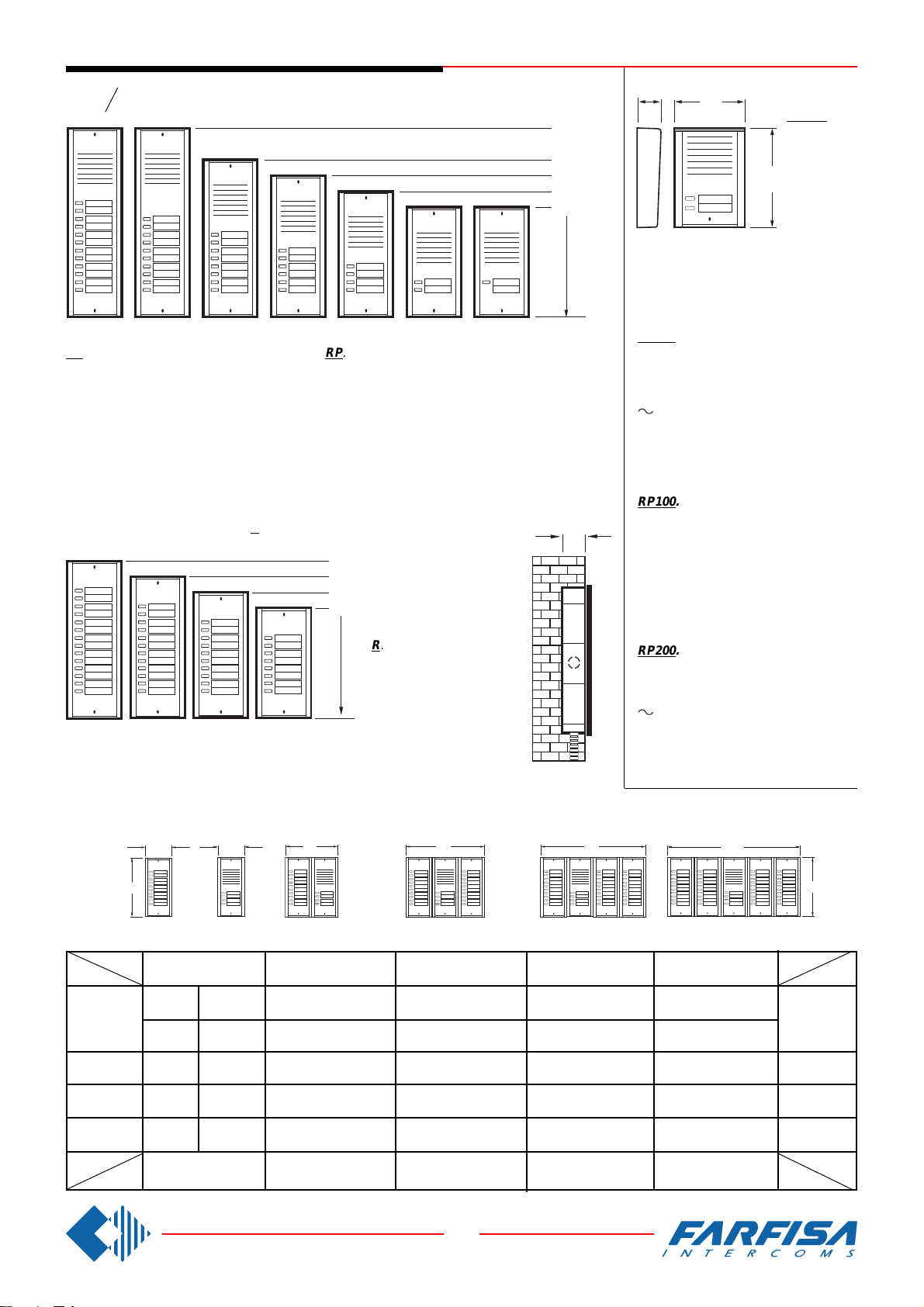
Modularity of the various push-button panels (ErreP/R Series) and their dimensions
Kompatibilität der unterschiedlichen Türstationen und Klingelplatten der Serie ErreP/R und entsprechenden Abmessungen
L and/
und
H = Dimensions of panels /
L
Maße der Frontplatte
L
l and
L
/und
h = Dimension of wall boxes /
Maße der Unterputzgehäuse
L
L
H
Series R RP R+RP R+RP+R R+RP+R+R R+R+RP+R+R
H
L
112mm 224mm 336mm 448mm 560mm
R8 RP1 R8+RP1=9 2R8+RP1=17 3R8+RP1=25 4R8+RP1=33
219 207
R8 RP2 R8+RP2=10 2R8+RP2=18 3R8+RP2=26 4R8+RP2=34
250 R10 RP4 R10+RP4=14 2R10+RP4=24 3R10+RP4=34 4R10+RP4=44 238
282 R12 RP6 R12+RP6=18 2R12+RP6=30 3R12+RP6=42 4R12+RP6=54 270
313 R14 RP8 R14+RP8=22 2R14+RP8=36 3R14+RP8=50 4R14+RP8=64 301
H
l
103mm 215mm 327mm 439mm 551mm
15
8 GbD-'02
H
L
h
h
l
Page 18
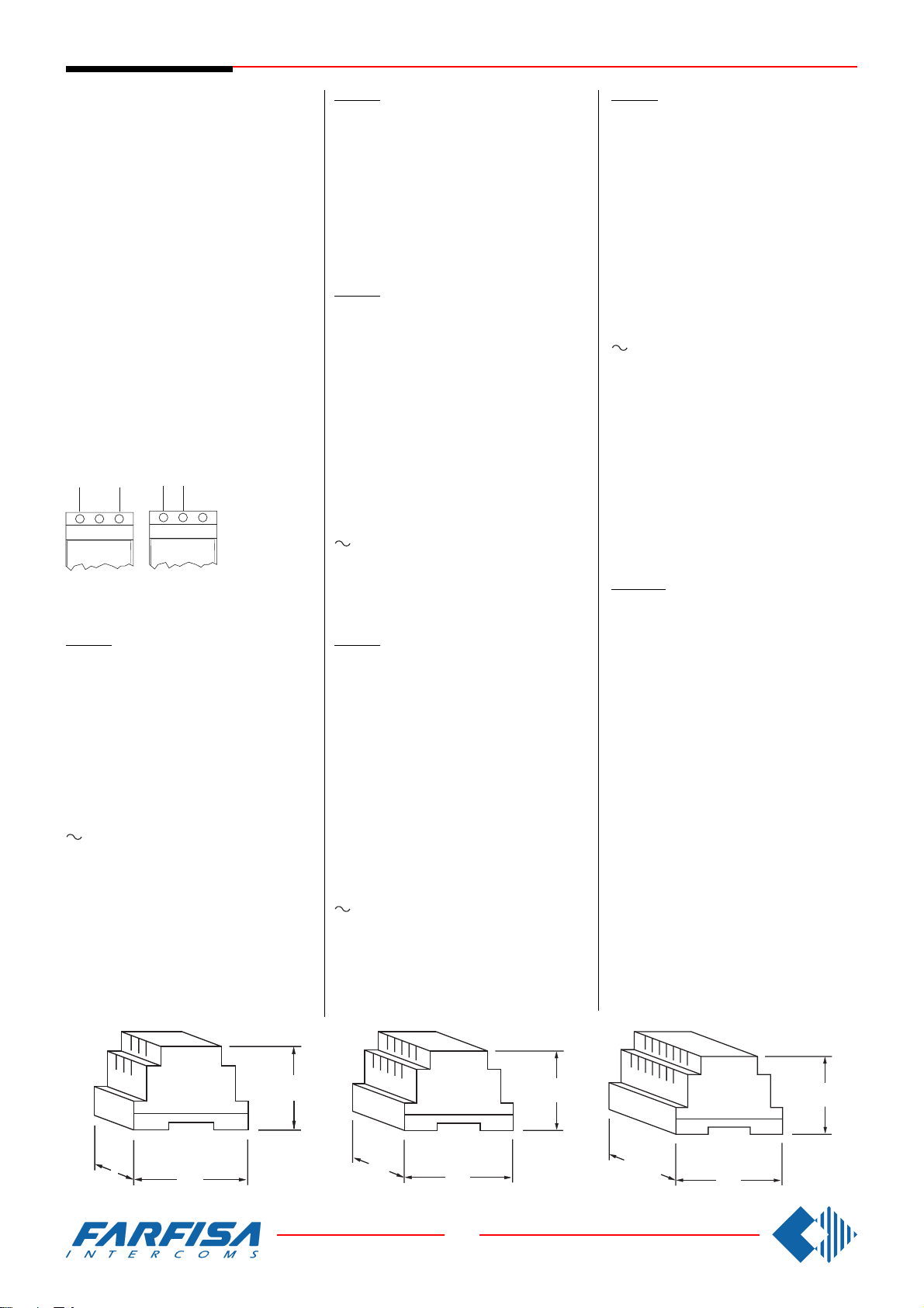
POWER SUPPLIES
The power supply is not provided with fuses,
but it is protected against overloading or shortcircuiting by a heat sensor (thermoprotector),
to restore power, it is necessary to cut off the
mains voltage for about one minute. Reconnect
power after having repaired the fault.
Do not obstruct the openings or the ventilation
or heat ejection slots to allow the equipment to
operate correctly. The power supply can be
installed on DIN rail or screwed to the wall.
All the power supplies described in this manual
replace the corresponding ones with similar
initials. E.g.: PRS220 replaces PRS220D,
PRS220K, etc. PRS226 replaces PRS226D
and PRS226K.
All power supplies can provide power for a
maximum of 8 24V-3W lamps for illuminating
push-button panel name plates. For more than
8 lamps, PRS210 transformer should be
installed.
General technical data
Input voltage: 127V or 230Vac
Working temperature: 0°÷+50°C
Maximum of humidity: 90%RH
Warning
230V
127V
0 230V
PRS220. STABILIZED POWER SUPPLY.
It is provided to supply 4+1 intercom systems
(electric door lock, name plate lamps, electric
door-speakers, amplifier, etc.)
Technical data
Power: 15VA
Housing: DIN 4 modules A
Weight: 0.45 Kg.
Approved by: VDE-SEMKO-DEMKO-SASO
Output terminals
127V
127V
0 230V
All power
supplies in this
manual can work
either 127VAC or
230VAC.
Check carefully
the right
connection.
- Ground
+ Audio line power supply 6Vdc-0.1A
Power supply 13Vac for:
- name plate lamps, exchangers
(continuous load 0.6A)
- electric door lock and bells (intermittent
load 1A)
PRS210. TRANSFORMER
It is provided to supply amplified door stations,
additional door locks, name plate lamps, etc.
Technical data
Power: 15VA
Output voltage: 13Vac
Maximum load: 0.7A
Maximum of intermittent load: 1A
Housing: DIN 3 modules A
Weight: 0.42 Kg.
Approved by: VDE
PRS240. STABILIZED POWER SUPPLY WITH
ELECTRONIC BELL.
It may be installed with 4+1 intercom systems
for receiving different calls (buzzer and electronic
bell; power supply is complete with electronic
bell).
Technical data
Power: 18VA
Bell frequency: 450Hz modulated
Housing: DIN 6 modules A
Weight: 0.5 Kg.
Approved by: VDE
Output terminals
- Ground
+ Audio line power supply 7.2Vdc-0.1A
X Power supply for aux. services 12Vdc-0.2A
Power supply 13Vac for:
- name plate lamps (continuous load 0.6A)
- electric door lock and bells (intermittent
load 1A)
C+ Electronic bell output 10Vpp-0.2A
PRS235. POWER SUPPLY FOR SYSTEMS
WITH PRIVATE CONVERSATION MODULE.
It may be installed with Project series intercoms
for supplying power to 4+1 systems with private
conversation module. Only the intercom which
has been called can speak to the door station.
All the other users are isolated.
Technical data
Power: 18VA
Housing: DIN 6 modules A
Weight: 0.5 Kg.
Approved by: VDE
Output terminals
- Ground
+ Audio line power supply 7.2Vdc-0.1A
X Power supply for auxiliary services 12Vdc-
0.2A
Power supply 13Vac for:
- name plate lamps (continuous load 0.6A)
- electric door lock and bells (intermittent
load 1A)
C+ Power supply for bells 13Vac- 0.15A
PRS226. STABILIZED POWER SUPPLY/
SWITCHER.
It is able to supply intercommunicating intercom
systems and to switch over automatically audio
connection of the door station and of the
intercommunicating service to the intercoms.
Technical data
Power: 18 VA
Housing: DIN 6 modules A
Weight: 0.5 Kg.
Approved by: VDE
Output terminals
- Ground
+ Audio line power supply 8Vdc-0.1A
X Power supply for auxiliary services 12Vdc-
0.2A
Power supply 13Vac for:
- name plate lamps, exchangers
(continuous load 0.6A)
- electric door lock and bells (intermittent
load 1A)
7 Power supply 13Vac for electric door lock
and bells (intermittent load 1A)
A Output for call from push-button panel
13Vac-0.15A
G Audio line receiver from intercoms
2 Audio line transmitter to intercoms
D Audio line transmitter to electric door
speaker
C+ Audio line receiver from electric door
speaker
PRS226E. STABILIZED POWER SUPPLY/
SWITCHER.
As above, with the following additional terminals and the modification of terminal 7.
7 Electronic bell output for intercommuni-
cations
Y Electronic bell output for push-button panel
9 Electronic call input for switching over multi-
way installations
4 Relay switching common terminal
controlled from entrance 9
4a NC relay switching controlled from entrance
9
4b NA relay switching controlled from entrance
9
53.5
89
65
70
89
16
8 GbD-'02
65
DIN 6DIN 4DIN 3 PRS 210 PRS 220
107.5
89
65
PRS 226
PRS 226E
PRS 240
PRS 235
Page 19
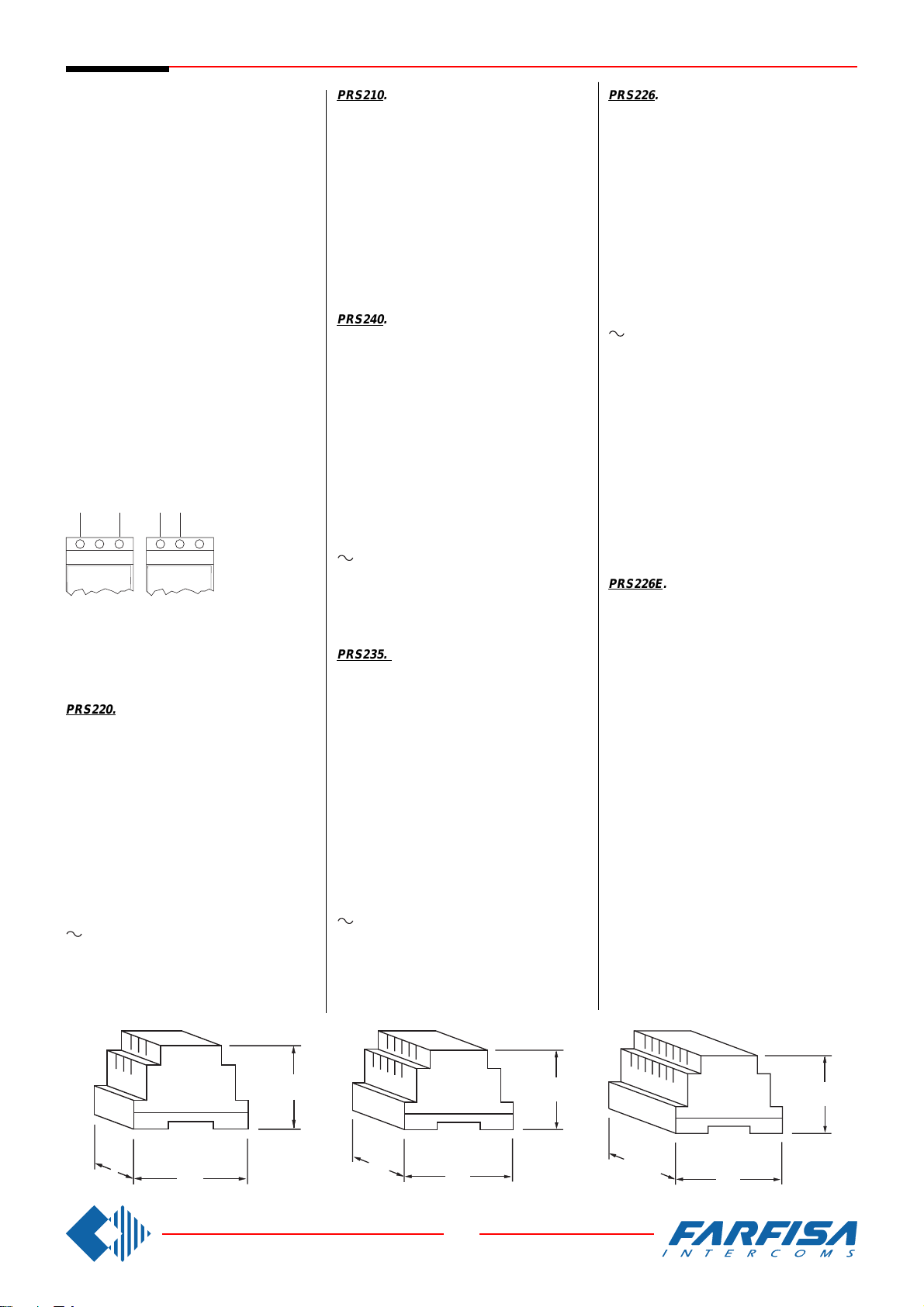
NETZTEILE
Alle Netzteile enthalten keine Sicherungen,
alle Ausgänge sind aber gegen Überlastung
oder Kurzschluß durch Temperatursensoren
(Temperaturschutzschalter) geschützt. Um
nach einem Ausfall das Gerät wieder einzuschalten, reicht es die Netzspannung für ca. 1
Minute abzuschalten und diese nach dem Beheben des verursachenden Defektes wieder
einzuschalten. Die Versorgungseinheit muß
an einem trockenen Ort installiert werden. Die
Öffnungen und Lüftungsschlitze für die Wärmeableitung dürfen nicht verstopft werden, sonst
könnte der einwandfreie Betrieb des Gerätes
gefährdet werden. Alle Netzgeräte können auf
DlN Hutschienen installiert oder an die Wand
montiert werden. Alle Netzgeräte haben eine
Leistung für die Versorgung von max. 8 Stück
24V-3W Soffittenlampen für die Namensschilderbeleuchtung der Klingelplatten und Türstationen. Für eine höhere Anzahl von Lampen
müssen entsprechende PRS210 Klingeltrafo
eingesetzt werden.
Allgemeine Technische Daten
Netzspannung: 127V oder 230Vac
Betriebstemperatur: 0° bis +50°C
Luftfeuchtigkeit: max 90% RH
Bitte beachten
230V
127V
0 230V 127V
sprechen alle Geräte der Schutzklasse II und
benötigen dadurch KEINEN ERDANSCHLUß.
Bitte beachten Sie genau auf den richtigen
Anschluß.
PRS220. STABILISIERTES NETZTEIL FÜR
SPRECHANLAGEN.
Einsetzbar zur Versorgung von 4+n Türsprechanlagen (elektrischer Türöffner,
Namensschildbeleuchtung, Türfreisprecheinrichtung, usw.).
Technische Daten
Leistung: 15VA
Gehäuse: 4 DIN A Module
Gewicht: 0,45 kg
Zulassungen:VDE - SEMKO – DEMKO - SASO
Anschlußklemmen
- Masse
+ +6Vdc/ 0,1A
13Vac für: Namensschilderbeleuchtung,
Umschalter (Dauerbetrieb 0,6A), elektrischer Türöffner und Rufstrom (zeitbegrenzter Betrieb 1A)
127V
0 230V
Alle nachfolgenden beschriebenen Netzteile können mit einer Netzspannung von
127V oder 230V
betrieben werden.
Weiterhin ent-
PRS210. KLINGELTRAFO.
Der Klingeltrafo wird für die Versorgung der
verstärkten Türstationen mit integrierter Türfreisprecheinrichtung, zusätzliche Türöffner,
Namensschildbeleuchtungen, usw. eingesetzt.
Technische Daten
Leistung: 15VA
Ausgangsspannung:13Vac
Max. Dauerstrom: 0,7A
Max. Impulsstrom: 1A
Gehäuse: 3 DIN A Module
Gewicht: 0,42kg
Zulassungen: VDE
PRS240. STABILISIERTES NETZTEIL MIT
ELEKTRONISCHEM TONRUF.
Einsetzbar zur Versorgung von 4+n Türsprechanlagen mit Rufunterscheidung (Summer und
elektronischer Tonruf aus dem Netzteil).
Technische Daten
Leistung: 18VA
Tonruf: 450 Hz Alphaton
Gehäuse: 6 DlN A Module
Gewicht: 0,5 kg
Zulassungen: VDE
Anschlußklemmen
- Masse
+ +7,2Vdc/0,1A
X +12Vdc/ 0,2A für Zusatzeinrichtungen
13Vac für: Namensschilderbeleuchtung,
Umschalter (Dauerbetrieb 0,6A), elektrischer Türöffner und Rufstrom (zeitbegrenzter Betrieb 1A)
C+ Ausgang Tonruf 10Vss/0,2A
PRS235. NETZTEIL FÜR ANLAGEN MIT
MITHÖRSPERRE.
Einsetzbat zur Versorgung von 4+n Türsprechanlagen mit Mithörsperre und den Haustelefone Serie Project. Ermöglicht die Verbindung
des gerufenen Haustelefons zur Türstation mit
Sprechgeheimnis zu allen anderen Teilnehmer.
Technische Daten
Leistung: 18VA
Gehäuse: DIN 6 Modules A
Gewicht: 0,5kg
Zulassungen: VDE
Anschlußklemmen
- Masse
+ +7,2Vdc/0,1A
X +12Vdc /0,2A für Zusatzeinrichtungen
13Vac für: Namensschilderbeleuchtung,
Umschalter (Dauerbetrieb 0,6A), elektr. Türöffner und Rufstrom (zeitbegrenzter Betrieb 1A)
C+ 13Vac Rufstrom /0,15A
PRS226. STABILISIERTES NETZTEIL MIT
UMSCHALTEINRICHTUNG.
Einsetzbar zur Versorgung von Gegensprechanlagen. Schaltet automatisch die Sprechverbindung zwischen Türstation und Internsprechweg um.
Technische Daten
Leistung: 18VA
Gehäuse: 6 DIN A Module
Gewicht: 0,5kg
Zulassungen: VDE
Anschlußklemmen
- Masse
+ +8Vdc /0,1A
X +12V dc /0,2A für Zusatzeinrichtungen
13Vac für: Namensschilderbeleuchtung,
Umschalter (Dauerbetrieb 0,6A), elektrischer Türöffner und Rufstrom (zeitbegrenzter Betrieb 1A)
7 13Vac für elektrischer Türöffner u. Rufst-
rom-zeitbegrenzter Betrieb 1A
A Rufstromausgang für Klingeltast.13Vac/
0,15A
G Sprechweg Empfangsrichtung von den
Haustelefonen
2 Sprechweg Senderichtung zu den Hauste-
lefonen
D Sprechweg Senderichtung zu der Türfrei-
sprecheinrichtung
C+ Sprechweg Empfangsrichtung von der
Türfreisprecheinrichtung
PRS226E. STABILISIERTES NETZTEIL MIT
UMSCHALTEINRICHTUNG.
Wie oben, aber mit folgenden Zusatzklemmen
und einer Änderung bei Klemme 7.
7 Ausgang elektronisches Läutwerk für Ge-
gensprechverkehr
Y Ausgang elektronisches Läutwerk für Tür-
station
9 Eingang elektronischer Klangrufnote zur
Umschaltung in Mehrfamilienanlagen
4 Gemeinsame Weiche des von Eingang 9
gesteuerten Steuerkontakts
4a NC-Weiche des von Eingang 9 gesteuerten
Steuerkontakts
4b NA-Weiche des von Eingang 9 gesteuerten
Steuerkontakts
53.5
89
65
70
89
17
8 GbD-'02
65
DIN 6DIN 4DIN 3 PRS 210 PRS 220
107.5
89
65
PRS 226
PRS 226E
PRS 240
PRS 235
Page 20
1
2
3
4
5
11
12
13
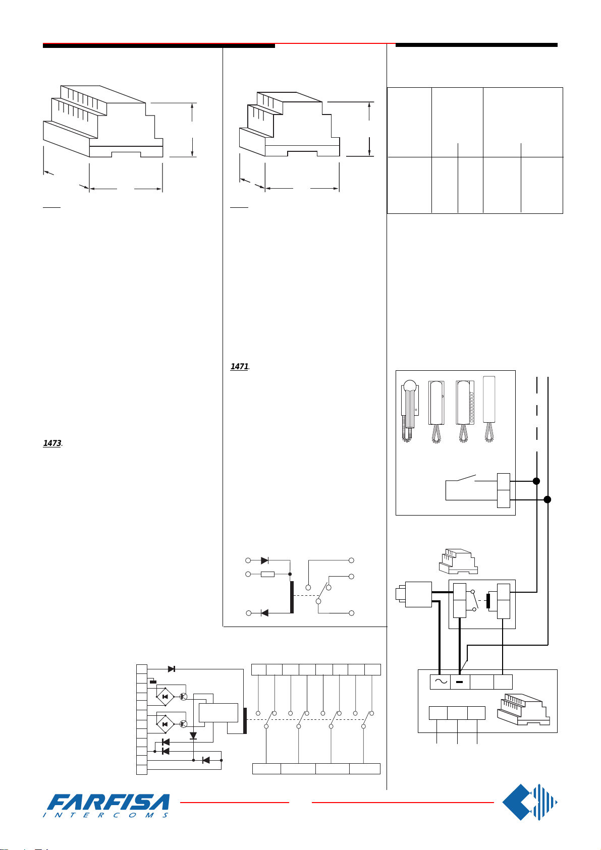
SERVICE MODULES /
SERVICEMODULE
CABLES /
VERBINDUNGSKABELN
Exchanger
Umschalter
73
140
1473. It is installed in intercom systems with two
or more entrances for switching the audio lines
and door lock of the calling entrance. It can be
installed on DIN bar or with two screws. In housing
DIN bar 8 modules A.
Terminals
1 Power supply 13Vac-0.1A
2 Ground
3 and 4Driver to switch the relay to “b” position -
ON position
5 and 6 Driver to switch the relay to “a” position -
rest condition
7, 8, 9 and 10 Common relay contacts
7a, 8a, 9a and 10aOFF position of the relay con-
7b, 8b, 9b and 10b ON position of the relay
11 Logical driver to switch the relay to “a” position
- rest condition
12 Logical driver to switch the relay to “b” position
- ON position
13 Electronic bell input from PRS240
1473. Wird bei Anlagen mit zwei oder mehreren
Türstationen eingesetzt. Es ermöglicht die Umschaltung der Sprechwege und der Türöffnungsteuerleitungen zu der anrufenden Türstation. Die
Installation erfolgt auf DIN Hutschiene oder Wandmontage. Das Gerät ist in einem 8 DlN A Module
Gehäuse untergebracht. Die Art.Nr.1473 ersetzt
das Modell 473.
Anschlußklemmen
1 Stromversorgung 13Vac 0,1A
2 Masse
3 und 4 Steuerung für Umschaltung der Kontak-
5 und 6 Steuerung für Umschaltung der Kontak7, 8, 9 und 10 Eingang umschaltbare Kontakte
7a, 8a, 9a und 10a Ausgang umschaltbare
7b, 8b, 9b und 10b Ausgang umschaltbare
11 Logischer Steuereingang um Umschalter auf
12 Logischer Steuerein-
13 Steuereingang mit
te auf Position “b” - Selbsthaltezustand
te auf Position “a” - Ruhezustand
Kontakte im Ruhezustand
Kontakte im Selbsthaltezustand
Stellung “a” - Ruhezustand umzuschalten
gang um Umschalter
auf Stellung “b” Selbsthaltezustand
umzuschalten
elektronischem Tonruf aus PRS240
89
tacts
contacts
1
2
3
4
5
6
11
12
13
Relay unit
Universalrelais
53.5
89
1471. A low voltage, low current (DC/AC)
unit, it can switch voltages up to 50V and
5A max. Used for auxiliary services (e.g.
stair lights, call for 3 or more bells, door
release etc).
It can be installed on DIN bar or with two
screws. In housing DIN bar 3 modules A.
Terminals
1 13Vac input
2 24Vdc input
3 Ground
5 Common relay
6 Relay contact - ON
7 Relay contact - OFF
1471. Durch Schwachstromsignale (Gleich-
strom oder Wechselstrom) können hiermit
Starkstromverbraucher gesteuert werden.
Die max. Belastung beträgt 5A bei 50V.
Einsetzbar für die Steuerung von
Zusatzeinrichtungen (z.B. Treppenlicht,
gleichzeitiger Ruf auf 4 oder mehr Summer, Türöffnung, usw.). Installation auf DIN
Hutschiene oder Wandmontage. Das Gerät ist in einem 3 DIN A Module Gehäuse
untergebracht.
Anschlußklemmen
1 Eingang Wechselspannung 13 Vac
2 Eingang Gleichspannung 24 Vdc
3 Masse
5 Gemeinsamer Eingang für Kontakt
6 Ausgang Kontakt Arbeitstellung
7 Ausgang Kontakt Ruhestellung
1
2
3
7a 8b
ON (b)
OFF (a)
7b
MEMORY
7
8a
8
9b
SECTION
DURCHMESSER
audio line
and calls
Sprechweg
und
Rufleitungen
65
distance
in metres
Entfernung
in meters
mm²
50
100
200
300
For distances over 300m door release should
be activated by means of the relay unit art.1471.
In order to avoid A/C trouble, supply it with
continuous current by using the power supply
PRS226, PRS231, PRS240 or PRS235.
Für größere Entfernungen wird geraten, das
Türschloß mit dem Universalrelais Art.Nr. 1471
zu steuern. Um sicherzustellen das keine
Wechselstromstörungen auftreten, sollte dieser mit einer Gleichstromspannung mit Hilfe
der Netzteile PRS226, PRS231, PRS240 oder
PRS235 versorgt werden.
0.25
0.35
0.5
0.75
Intercom
Haustelefon
6
7
SE
5
door lock and ground
(cables in bold face type)
Türöffner und Masse
(Fettgedruckte
Leitungen)
mm²
mm
0.5
0,5
1
0,7
2
0,8
2.5
1
CT
1471
5
6
mm
0,8
1,2
1,6
1,8
5
3
3
1
IN
10b
9a
9
10
10a
230V 127V 0
X
AL
Power supply
Netzteil
18
8 GbD-'02
Page 21

WORKING INSTRUCTIONS / TROUBLESHOOTING
Basic systems
For all the intercom systems, simply lift the
handset to speak to the door station. The call
is indicated by an audio signal (a buzzer or an
electronic bell).
To activate the door release, press the pushbutton with the key symbol. In systems with two
or more entrances the communication and
door release are switched automatically on the
entrance from which the call is made while the
other entrances are isolated.
Systems with private conversation module
In all standard intercom systems (not intercommunicating) a private audio system can be
provided (only the intercom which has been
called can speak to the door station) by installing the “private conversation module" art.SM50
in every intercom. Since the buzzer rings, the
user has about 40 seconds to lift handset and
answer. There is no time limit for the private
conversation. When the handset is replaced
the system returns to the rest condition. If a
user does not replace the handset properly,
the next call from another intercom, automatically cuts him out of the audio connection with
the door station.
Intercommunicating systems
Intercommunicating systems allow users to
speak to one another by simply lifting the
handset; any user can join in to a conversation
already in progress. To avoid interferences it is
necessary to observe the following instructions.
Lift the handset, make sure that there is not a
conversation already in progress, then press
the call push-button corresponding to the desired user.
Intercommunicating systems connected to
door station
Such systems allow conversation between two
or more inside users with the exclusion of the
door station, or between one inside user and
the door station.
When there is a call from an external pushbutton panel the audio line of the electric door
speaker is activated automatically; when one
calls from one of the intercoms, the internal
intercommunicating audio line is automatically
activated.
The user called has simply to lift the handset.
Any user can join in to a conversation already
in progress.
To avoid interferences it is necessary to observe the following instructions:
lift the handset, make sure that there is not a
conversation already in progress, then press
the call push-button corresponding to the desired user.
As it is shown in the connection diagram,
internal calls have a sound (electronic) distinct
from external calls (buzzer). The electronic
sound is obtained by means of the electronic
bell module art.SR40 installed inside the intercom. To activate the electric lock it is necessary to push the push-button with a key symbol
on. By performing this operation the system
returns to the intercommunicating service with
the audio exclusion of the door station.
Preliminary checks
- Check for the presence of the mains voltage
in the terminals 230Vac (or 127Vac) of the
power supply.
- The power supply is not provided with fuses,
but it is protected against overloading or shortcircuiting by a heat sensor (thermoprotector),
to restore power, it is necessary to cut off the
mains voltage for about one minute. Reconnect power after having repaired the fault.
- Check the voltage output of the power supply
(see in detail the values indicated in the power
supply chapter).
- Check that the cross section of the cables
corresponds to what is indicated on page 18
and in the descriptions of each individual diagram.
Fault and probable damage
Nothing at all is working
Absence of main voltage. Short-circuit or overload of the terminals of the power supply
output. Faulty power supply.
The lock does not work
Faulty lock. The cross section of the cables
indicated in bold type is insufficient. A connecting cable to the lock has been interrupted.
Faulty power supply.
Calls from the door station do not activate
The common connection of the push-buttons
on the push-button panel has been interrupted.
A call to an individual intercom does not
activate
The connecting wire from the door station to
the intercom has been interrupted. The intercom buzzer is faulty or badly set. In intercoms
with electronic call check that the handset is
hung up correctly.
No sound from either channel
Absence of power between 3 (+) and 4 ( - ) of
the electric door-speaker (6÷8Vdc). Short-circuit between + and - of the power supply.
Faulty power supply.
No sound from the intercoms to door station
Connection 1 from the intercoms to the electric
door-speaker has been interrupted or shortcircuited. There is no ground connection to
terminal 4 of the electric door-speaker (amplifier). Faulty electric door-speaker (amplifier).
No sound from the door station to the intercoms
Connection 2 from the intercoms to the electric
door-speaker (amplifier) has been interrupted
or short-circuited. Faulty electric door-speaker
(amplifier).
Sound with humming in the background
(50/60Hz)
The cables have been canalized together with
cables supplying a/c high absorption loads.
Separate the ground connection of the electric
door-speaker (amplifier) and of the name plate
lamps; a conductor from - (minus) of the power
supply to 4 of the electric door-speaker (amplifier), another conductor from - (minus) of the
power supply to the lamps. Faulty power supply.
At the door station a whistle is heard
(Larsen effect)
The electric door-speaker (amplifier) is badly
housed in the push-button panel; the microphone has to be stuck to plate. Lower the
volume.
Radio reception on the door station
The defect can occur when there is a transmitter working in the proximity. Apply a condenser
from 0.1µF between terminals 1 and 3 of the
electric door speaker (amplifier).
Intercommunicating systems
No sound in either channel. Intercommunicating phone not working
Short-circuit between + and - of the power
supply. Faulty power supply.
Calls from the door station activate. No
sounds in either channel. Intercommunicating phone is working
No power supply between 3 (+) and 4 (-) of the
electric door-speaker (8Vdc). Faulty power
supply.
No sounds from the intercoms to the door
station
The connection between 1 of the intercoms
and G of the power supply has been interrupted. The connection between D of the power
supply and 1 of the electric door-speaker (amplifier) has been interrupted. Faulty electric
door-speaker (amplifier). Faulty power supply.
No sounds from the door station to the
intercoms
The connection between 2 of the intercoms
and 2 of the power supply has been interrupted. The connection between C+ of the
power supply and 2 of the electric door-speaker
(amplifier) has been interrupted. Faulty electric
door-speaker (amplifier). Faulty power supply.
The intercommunicating calls activate, but
the door station is still on
Check that cable 7 is connected to 7 of the
power supply and not to terminal . Faulty
power supply.
The intercommunicating calls do not activate
Check that cable 7 is connected to 7 of the
power supply. Faulty power supply.
No sound in the intercommunicating service
Faulty power supply.
System with more entrances
Entrance A is never activated
Short-circuit between 5 and 6 of the exchanger.
Faulty exchanger.
Entrance B is never activated
Short-circuit between 3 and 4 of the exchanger.
Faulty exchanger. No power supply to 1 and 2
of the exchanger (12Vac).
19
8 GbD-'02
Page 22

FUNKTIONSBESCHREIBUNG / FEHLERSUCHE
Türsprechanlage.
Bei allen Türsprechanlagen reicht es den Handapparat abzuheben um mit der Türstation zu
sprechen. Der Anruf wird akustisch mit einem
Summer oder elektronischen Klangruf signalisiert. Zum Öffnen des Türschlosses muß die
Taste mit dem Schlüsselsymbol betätigt werden. Bei Anlagen mit 2 oder mehrere Türstationen, wird der Sprechweg und die
Türöffnungsteuerleitung automatisch auf die rufende Türstation umgeschaltet. Alle anderen
Türstationen bleiben getrennt.
Türsprechanlage mit Mithörsperre.
In allen Türsprechanlagen (ohne internen Gegensprechverkehr) ist es möglich eine Mithörsperre (nur das angerufene Haustelefon ist berechtigt mit der Türstation zu sprechen) einzurichten. Hierzu muß in jedem Haustelefon das
Mithörsperrmodul Art.Nr.SM50 eingebaut werden. Ab dem Augenblick wo der Summer ertönt,
hat der Teilnehmer 40 Sek. Zeit zum Antworten.
Nach dem Abheben des Handapparates kann er
für eine unbegrenzte Zeit sprechen. Nach Auflegen des Handapparates setzt sich das System
automatisch in Ruhestellung zurück. Falls der
Teilnehmer den Hörer nicht richtig auflegt, wird
er, mit dem Anruf zu einem anderen Haustelefon, automatisch von der Sprechverbindung zur
Türstation getrennt.
Gegensprechanlagen ohne Türstation.
Die Gegensprechanlagen ermöglichen eine interne Sprechverbindung zwischen Haustelefone. Die Verbindung kommt mit der einfachen
Abnahme des Handapparates bei den beteiligten Teilnehmern. Jeder beliebige Teilnehmer
kann sich in die geführte Unterhaltung einschalten.
Gegensprechanlagen mit Verbindung zur
Türstation.
Diese Anlagen ermöglichen ein Gespräch zwischen 2 oder mehreren internen Teilnehmer zu
führen, dabei wird die Türstation abgeschaltet.
Oder es kann auch ein Gespräch zwischen
Haustelefon und Türstation erfolgen. Mit dem
Anruf von der Türstation wird automatisch die
Sprechverbindung der Türfreisprecheinrichtung
durchgeschaltet. Erfolgt der Anruf von einem der
Haustelefone, wird automatisch die interne
Gegensprechverbindung durchgeschaltet. Die
Sprechverbindung zur Türstation bleibt während der Internverbindung getrennt. Der angerufene Teilnehmer muß nur den Handapparat abheben um das Gespräch aufnehmen zu können.
Jeder Teilnehmer kann sich in eine laufende
Sprechverbindung einschalten. Zum Vermeiden
von Störungen sollte man folgende Richtlinien
folgen: Handapparat abheben und sich vergewissern das kein Gespräch geführt wird, dann
Ruftaste des gewünschten Teilnehmers betätigen und nach Antwort das gewünschte Gespräch führen. In den Schaltplänen ist für den
internen Ruf ein elektronischer Klangruf und für
den externen Ruf ein Summer vorgesehen. Dieser elektronischer Ruf wird mit Hilfe des Klangrufmoduls Art.Nr.SR40 erzeugt. Dieser wird innerhalb der Haustelefone eingebaut. Zur Aktivierung des elektrischen Türschlosses muß die
Taste mit dem Schlüsselsymbol betätigt werden. Dadurch wird die Anlage auf internen Gegensprechverkehr mit getrennter Türstation zurückgeschaltet.
Vorläufige Untersuchungen.
– Prüfen Sie ob die Netzversorgung zwischen
den Anschlüssen 230 (bzw. 127) und 0 auf dem
Netzgerät vorhanden ist, und ob die Netzversorgung sich in den angegebenen Tolleranzen befindet.
- Das Netzgerät besitzt keine Schmelzsicherungen. Alle Ausgänge sind aber gegen
Überlastung und Kurzschluß mit Temperaturfühlern geschützt. Um die Temperaturunterbrechung am Netzteil zurückzusetzen, müssen
Sie die Netzversorgung für etwa eine Minute
abschalten und den Defekt entfernen.
- Prüfen Sie die Ausgangsspannungen des Netzgerätes. Sehen Sie hierzu die entsprechenden
Beschreibungen im Kapitel Netzteile.
- Prüfen Sie den Durchmesser der verwendeten
Kabel, ob diese der empfohlenen Richtlinien auf
der Tabelle auf Seite 18 entsprechen.
FEHLER UND MÖGLICHE URSACHEN
Totalausfall.
Netzversorgung nicht vorhanden. Ein Kurzschluß
hat die Ausgänge des Netzgerätes überlastet.
Fehler im Netzteil.
Der Türöffner funktioniert nicht.
Fehler im Türöffner. Der Durchmesser der benutzten Kabel ist nicht ausreichend. Die Verbindung zum Türöffner ist unterbrochen. Fehler im
Netzteil.
Keine Klingelrufe von der Türstation.
Die Versorgung des Rufstromes ist unterbrochen.
Zu einem Haustelefon erfolgen keine Rufe.
Die Rufleitung von der Türstation zum Haustelefon ist unterbrochen. Der Summer ist defekt oder
falsch eingestellt. Bei Haustelefone mit elektronischem Klangruf oder Rufton sicherstellen das
der Handapparat sicher aufliegt.
Keine Sprechverbindung in beiden Richtungen.
Fehlende Versorgungsspannung (6 bis 8 Vdc)
auf den Klemmen 3 und 4 der Türfreisprechein-
richtung. Kurzschluß zwischen den Verbindungen + und - auf dem Netzteil. Fehler auf dem
Netzteil.
Keine Sprechverbindungen zwischen Haustelefone und Türstation.
Die Verbindung 1 von den Haustelefone zur
Türstation ist unterbrochen oder hat einen Kurzschluß. Es fehlt die Erde auf der Klemme 4 der
Türfreisprecheinrichtung. Fehlerhafte Türfreisprecheinrichtung.
Keine Sprechverbindung von der Türstation
zu den Haustelefone.
Die Verbindung 2 von den Haustelefone zur
Türstation ist unterbrochen oder hat einen Kurzschluß. Fehlerhafter Türfreisprecheinrichtung.
Brummton auf den Sprechwegen (50/60 Hz).
Die Verbindungskabel der Anlage wurden zusammen mit Starkstromkabeln verlegt. Die Masse der Türfreisprecheinrichtung und der Beleuchtung müssen getrennt verlegt werden. Die
Beleuchtungslampen müssen, von den Verbindungen- (Minus) auf dem Netzteil, getrennt von
der Türfreisprecheinrichtung versorgt werden.
Fehlerhaftes Netzteil.
Auf der Türstation ist ein Pfeifton zu hören
(Rückkopplung).
Die Türfreisprecheinrichtung ist falsch eingebaut. Das Mikrofon muß die Frontplatte der
Türstation berühren. Lautstärken etwas reduzieren.
Auf der Türstation wird eine Radiosendung
empfangen.
Dies kann in der Nähe von Radiosender vorkommen. Installieren Sie einen 0,1µF Kondensator
zwischen den Schraubklemmen 1 und 3 des
Türlautsprechers.
GEGENSPRECHANLAGEN
Die Sprechverbindung im Gegensprech-
betrieb und Türsprechbetrieb funktioniert
nicht.
Kurzschluß auf den Ausgängen + und - des
Netzgerätes. Fehlerhaftes Netzgerät.
Die rufe von der Türsprechstelle funktionieren. Sprechverbindung im Gegensprechbetrieb vorhanden, Sprechverbindung im
Türsprechbetrieb in beiden Richtungen fehlt.
Die Versorgungsspannung (8 Vdc) zwischen
den Klemmen 3 (+) und 4 (-) auf der Türfreisprecheinrichtung ist nicht vorhanden. Fehlerhaftes Netzteil.
Keine Sprechverbindungen zwischen Haustelefone und Türstation.
Die Verbindung 1 von den Haustelefone zur
Anschlußklemme G auf dem Netzteil ist unterbrochen oder hat einen Kurzschluß. Die Verbindung zwischen der Klemme D auf dem Netzgerät und 1 auf der Türfreisprecheinrichtung ist
unterbrochen. Fehlerhafte Türfreisprecheinrichtung. Fehlerhaftes Netzteil.
Keine Sprechverbindung von der Türstation
zu den Haustelefone.
Die Verbindung zwischen der Klemme 2 von den
Haustelefone und 2 auf dem Netzteil ist unterbrochen. Die Verbindung zwischen C+ auf dem
Netzgerät und 2 auf der Türfreisprecheinrichtung
ist unterbrochen. Fehlerhafte Türfreisprecheinrichtung. Fehlerhaftes Netzgerät.
Während den Internverbindungen ist die Türsprechstelle eingeschaltet.
Versichern Sie sich das die Verbindung 7 auf der
Klemme 7 des Netzteiles angeschlossen ist und
nicht auf der Klemme
Es erfolgen keine Gegensprechanrufe.
Versichern Sie sich das die Verbindung 7 auf der
Klemme 7 des Netzteiles angeschlossen ist.
Fehlerhaftes Netzteil.
Die Sprechverbindung im Gegensprechbetrieb funktioniert nicht.
Fehlerhaftes Netzteil.
ANLAGE MIT MEHREREN TÜRSTATIONEN
Die Türstation A wird nicht eingeschaltet.
Kurzschluß zwischen den Verbindungen 5 u. 6
auf dem Umschalter. Fehlerhaftes Umschalter.
Die Türstation B wird nicht eingeschaltet.
Kurzschluß zwischen den Verbindungen 3 und 4
auf dem Umschalter. Fehlende Stromversorgung auf den Eingängen 1 und 2 des Umschal-
ters (12Vac).
.
Fehlerhaftes Netzteil.
20
8 GbD-'02
Page 23

INSTALLATION DIAGRAMS
SCHALTPLÄNE
The following pages show the installation diagram most often made
used in the intercom sector.
Multifamily systems with 1, 2 and 3 entrances.
Multifamily systems with main entrance and secondary entrances.
Multifamily systems with private conversation module.
Multifamily systems with reduced number of cables.
Intercommunicating systems without door station.
Intercommunicating system with 1 and 2 entrances with individual or shared call.
It must be remembered that for a clearer understanding of the diagrams, the sequence of terminals in each individual article is not
to be followed. Only the terminal code is valid (letter and/or number)
not the graphic sequence.
The items may have more terminals than the ones in the installation
diagrams. The excess terminals must not be utilized.
The cable runs of any intercom unit must be kept separate from the
mains as required by international standards.
It is advisable to provide behind the power supply a disconnecting and
safety switch.
Before connecting the unit, make sure its data corresponds to those of
the mains.
The intercommunicating installation diagrams connected to 1 or
more door stations allow for the use of 5 intercommunicating intercoms. If a different number is required, the installation diagrams
presented in the back pages should be looked at, paying attention to
the type of installation (common call from door station, individual
buzzer call from door station and intercommunicating buzzer or electronic call). The installation diagram to use (2, 3 or 4 intercoms) should
be also photocopied and overimposed to the 5 intercoms base diagram.
For example: photocopying the installation diagram of 4 intercommunicating intercoms on page 41 and applying it to the installation diagram
on page 39 (laying out 6 cables at the riser) will produce a system of 4
intercommunicating intercoms connected to 2 door stations with
individual calls and electronic bells for internal calls.
Auf den folgenden Seiten finden Sie die am meisten verwendete Schaltpläne für Türsprechanlagen.
Mehrfamilienhausanlagen mit 1, 2 und 3 Türstationen
Mehrfamilienhausanlagen mit Haupt- und Nebeneingängen
Mehrfamilienhausanlagen mit Mithörsperre
Mehrfamilienhausanlagen mit vereinfachter Verkabelungstechnik
Interne Gegensprechanlagen ohne Türstation
Interne Einfamilien- oder Mehrfamilienhaus Gegensprechanlagen
mit 1 und 2 Türstationen
BITTE BEACHTEN
– Aus technischen Gründen und für eine bessere Übersicht der hier
vorhandenen Schaltpläne wurde die Reihenfolge der Anschlußleisten
der einzelnen Baugruppen nicht berücksichtigt. Maßgebend bei den
Anschlüsse sind nur die angegebenen Bezeichnungen (Nummer oder
Buchstaben).
- Die eingesetzten Baugruppen können mehr Anschlußpunkte haben, als
in den Schaltplänen dargestellt. Diese dürfen nicht angeschlossen
werden.
- Die Verlegung der Leitungen aller Sprech- und Videosprechanlagen
muß getrennt von den Starkstromanlagen erfolgen. Beachten Sie bitte
hierzu die entsprechenden VDE Richtlinien.
- Vor den Netzteilen ist der Einsatz eines entsprechenden Trennschutzschalters und Überspannungsfilter empfohlen.
– Bevor Sie die Anlage anschließen vergewissern Sie sich das die
Betriebsspannung der vorhandenen Netzspannung den Anforderungen
entspricht.
- Die Schaltpläne für Gegensprechanlagen mit eine oder mehreren
Türstationen sehen den Einsatz von 5 Haustelefone mit internem Gegensprechverkehr. Bei einer unterschiedlichen Anzahl von Haustelefone
benutzen Sie die hierfür vorgesehenen Anwendungsschaltpläne in den
letzten Seiten dieser Unterlagen. Beachten Sie dabei die entsprechende
Anlagenart (Einfamilienhaus oder Mehrfamilienhaus mit Rufunterscheidung). Wir empfehlen den notwendigen Anwendungsschaltplan zu
kopieren (mit 2, 3 oder 4 Haustelefone) und anstelle der auf dem
Grundschaltplan vorhandenen 5 Haustelefone einzusetzen.
This edition contains helpful information on the operation and installation of Farfisa intercom systems.
In order to make the systems work perfectly it is necessary to install
only Farfisa equipment, keeping strictly to the items referred to in each
diagram.
Read all the notes carefully, (even the small ones) in each installation
diagram and the working instructions of the system given in the
following pages.
Beispiel: wenn Sie den Anwendungsschaltplan mit 4 gegensprechende
Haustelefone auf Seite 41 kopieren und diesen auf dem Schaltplan auf
Seite 39 einsetzen, indem Sie ihn mit dessen 6 Hauptadern bündigen,
erhalten Sie eine Mehrfamilienhausanlage mit 4 Haustelefone mit internem Gegensprechverkehr, zwei Türstationen und Rufunterscheidung.
Auf Anfrage liefert Ihnen der Hersteller Schaltpläne für kundenspezifische Projekte die nicht in diesem Handbuch zu finden sind.
In diesen Unterlagen werden die Betriebsdaten sowie Installationshinweise der Farfisa Sprechanlagen beschrieben. Für den einwandfreien
Betrieb der hier beschriebenen Anlagen ist der Einsatz aller angegebenen Farfisa Originalteile notwendig. Folgen Sie hierzu genau die entspre-
chenden Stücklisten die sich bei jedem Schaltplan befinden.
Lesen Sie sorgfältig alle Bemerkungen und Warnungen, auch die Kleinsten.
Eine Funktionsbeschreibung der Anlagen finden Sie auf Seite 20.
21
8 GbD-02
Page 24
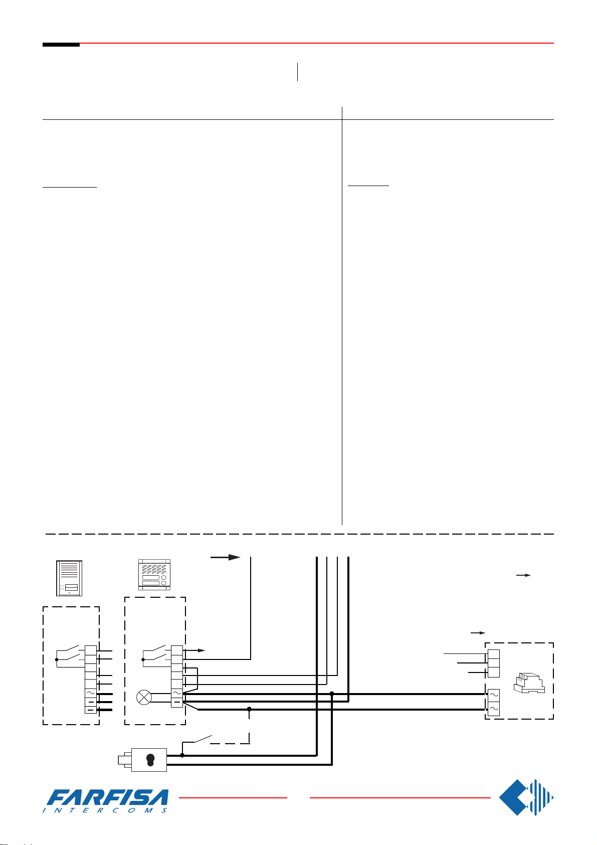
Si 100
INTERCOMS CONNECTED TO A DOOR STATION.
MEHRFAMILIENHAUS SPRECHANLAGE MIT EINER
TÜRSTATION.
Ref.diagram Q.ty Article Description
Schaltplan Bez. Menge Art.Nr.
CT ... PT510 * Intercom with 1 push-button
AL 1 PRS220 Power supply
SE 1 ** Electric door lock (12VAC-1A)
PA 1 ** Door release push-button (optional)
Door station
Series Mody (for right item set see on page 10, 11, 12 and 13)
MD ... MD71-72-73-74 MD71-72-73-74 Module frames with back box
PE 1 MD30 MD30 Electric door speaker
Series ErreP/R (see page 15)
MD 1 RP... Push-button panels
PE 1 337-C Electric door speaker
1 row 2 row
Einzeltasten Doppeltasten
1 MD10-11-12 MD10-122-124 Modules for electric door speaker
... MD21÷24 MD222÷228 Button modules
MD20-50 MD20-50 Blank and info modules
1 MD81÷812 MD81÷812 Hood covers
1 MD91÷912*** MD91÷912*** Rain shelters with module frames
... R... Push-button panels
1 290R2÷38 Rain shelters
Beschreibung
Haustelefon Serie Project
Netzteil
Elektrischer Türöffner (12Vac-1A)
Türöffnungstaste (Zusatztaste)
Türstation
Serie Mody (siehe Seiten 10,11, 12 und 13 für die Zusam-
mensetzung)
Unterputzgehäuse
Türsprechmodul
Ruftastenmodul
Leermodul - Hausnummermodul
Wetterschutzrahmen
Aufputzgehäuse
Türfreisprecheinrichtung
Serie ErreP/R (siehe Seite 15 für die Zusammensetzung)
Türstation
Klingelplatte
Aufputzgehäuse
Türfreisprecheinrichtung
Series TM (see page 14)
MD 1 T1M1÷T4M60 Push-button panels
PE 1 337-C Electric door speaker
... Refers to number of users.
* Besides the mentioned model all the intercoms from the Project,
PuntoVirgola, 900 and 700 can be installed.
** Articles not supplied by ACI Farfisa.
*** Rain shelters are used instead of back boxes and hood covers.
Working instructions: see page 19.
1 290/101÷460 Rain shelters
*
MD100
RP100
RP200
P2
P1
C
1
2
MD200
MD71 ÷ 74
xn
C
1
2
Serie TM (siehe Seite 14 für die Zusammensetzung)
Türstation
Aufputzgehäuse
Türfreisprecheinrichtung
... abhängig von der Anzahl der Teilnehmer.
* es können auch Haustelefone der Serien Project,
PuntoVirgola, 900 und 700 eingesetzt werden.
** diese Teile werden vom Hersteller nicht geliefert.
*** Die Aufputzgehäuse werden anstelle der Unterputz-
gehäuse eingesetzt und haben auch ein Wasserschutz-
rahmen.
Funktionsbeschrelbung: Siehe Seite 20.
For one or two family systems the amplified door stations
MD100, MD200, RP100, RP200 and UP series can be
installed. In this case superimpose the actual diagram
over that on page 23 laying it out at the riser
Für Ein- oder Zweifamilienhausanlagen können auch die
Türstationen mit eingebauter Türfreisprecheinrichtung
MD100, MD200, RP100, RP200 und serie UP eingesetzt
werden. In diesem Fall setzen Sie diesen Schaltplan auf
den nebenan bündig mit dem * gekennzeichneten
Trennpunkt.
230V
127V
0
*
.
PRS210
SE
PA
22
8 GbD-02
Page 25
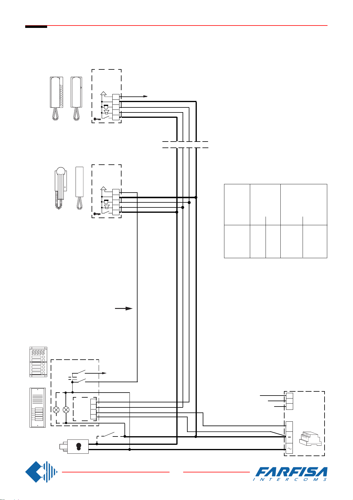
Si 100
INTERCOMS CONNECTED TO A DOOR STATION.
MEHRFAMILIENHAUS SPRECHANLAGE MIT EINER TÜRSTATION.
CT
4 + 1 intercoms
Sprechanlagen 4 + n
PT520
PV100
PT510
924
CT
6
3
1
2
5
6
3
1
2
5
xn
CABLE CROSS SECTION
DURCHMESSER VERBINDUNGENSKABEL
distance
in metres
Entfernung
in Meter
50
100
200
300
audio line
and calls
Sprechweg
und
Rufleitungen
mm²
0.25
0.35
0.5
0.75
door lock and ground
(cables in bold face type)
Türöffner und Masse
(Fettgedruckte
Leitungen)
mm
0,5
0,7
0,8
1
mm²
0.5
1
2
2.5
mm
0,8
1,2
1,6
1,8
Mody
ErreP/R
SE
PE
MD
1
2
3
4
PA
*
xn
230V
127V
0
23
8 GbD-02
AL
+
Page 26
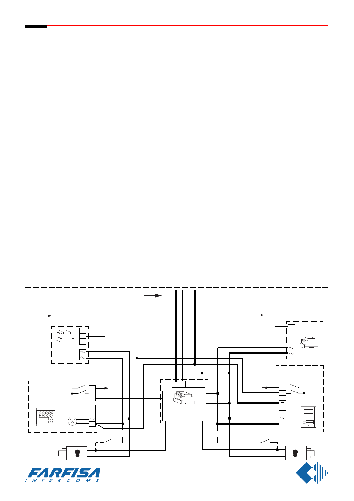
Si 120
INTERCOMS CONNECTED TO TWO DOOR STATIONS WITH AUTOMATIC SWITCHING.
Ref.diagram Q.ty Article Description
Schaltplan Bez. Menge Art.Nr.
CT ... PT510 * Intercom with 1 push-button
AL 1 PRS220 Power supply
DS 1 1473 Exchanger
SE 2 ** Electric door lock (12VAC-1A)
PA 2 ** Door release push-button (optional)
MEHRFAMILIENHAUS SPRECHANLAGE MIT ZWEI
UMSCHALTBAREN TÜRSTATIONEN.
Door station
Series Mody (for right item set see on page 10, 11, 12 and 13)
1 row 2 row
MD ... MD71-72-73-74 MD71-72-73-74 Module frames with back box
PE 2 MD30 MD30 Electric door speaker
Series ErreP/R (see page 15)
MD 2 RP... Push-button panels
PE 2 337-C Electric door speaker
Einzeltasten Doppeltasten
2 MD10-11-12 MD10-122-124 Modules for electric door speaker
... MD21÷24 MD222÷228 Button modules
MD20-50 MD20-50 Blank and info modules
2 MD81÷812 MD81÷812 Hood covers
2 MD91÷912*** MD91÷912*** Rain shelters with module frames
... R... Push-button panels
2 290R2÷38 Rain shelters
Beschreibung
Haustelefon Serie Project
Netzteil
Umschalter
Elektrischer Türöffner (12Vac-1A)
Türöffnungstaste (Zusatztaste)
Türstation
Serie Mody (siehe Seiten 10,11, 12 und 13 für die Zusam-
mensetzung)
Unterputzgehäuse
Türsprechmodul
Ruftastenmodul
Leermodul - Hausnummermodul
Wetterschutzrahmen
Aufputzgehäuse
Türfreisprecheinrichtung
Serie ErreP/R (siehe Seite 15 für die Zusammensetzung)
Türstation
Klingelplatte
Aufputzgehäuse
Türfreisprecheinrichtung
Series TM (see page 14)
MD 2 T1M1÷T4M60 Push-button panels
PE 2 337-C Electric door speaker
... Refers to number of users.
* Besides the mentioned model all the intercoms from the Project,
PuntoVirgola, 900 and 700 can be installed.
** Articles not supplied by ACI Farfisa.
*** Rain shelters are used instead of back boxes and hood covers.
For one or two family systems the amplified door
stations MD100, MD200, RP100, RP200 and UP
series can be installed. In this case superimpose the
actual diagram over that on page 25 laying it out at
the riser
and RP200 it is necessary to cut the jumper W1.
2 290/101÷460 Rain shelters
*
. In the amplified door stations RP100
0
127V
230V
*
PRS210
" a "
MD100
MD200
MD71 ÷ 74
xn
C
1
2
98753
6
7a
8a
9a
1473
Serie TM (siehe Seite 14 für die Zusammensetzung)
Türstation
Aufputzgehäuse
Türfreisprecheinrichtung
... abhängig von der Anzahl der Teilnehmer.
* es können auch Haustelefone der Serien Project,
PuntoVirgola, 900 und 700 eingesetzt werden.
** diese Teile werden vom Hersteller nicht geliefert.
*** Die Aufputzgehäuse werden anstelle der Unterputzgehäuse eingesetzt und haben auch ein Wasserschutzrahmen.
Für Ein- oder Zweifamilienhausanlagen können auch die
Türstationen mit eingebauter Türfreisprecheinrichtung
MD100, MD200, RP100, RP200 und serie UP eingesetzt
werden. In diesem Fall setzen Sie diesen Schaltplan auf den
nebenan bündig mit dem * gekennzeichneten Trennpunkt.
In den Türstationen
RP100 und RP200 muß
die Drahtbrücke W1
getrennt werden.
127V
" b "
230V
PRS210
0
RP100
RP200
xn
2
4
1
7b
8b
9b
P2
P1
C
1
2
SE
PA
24
8 GbD-02
PA
SE
Page 27
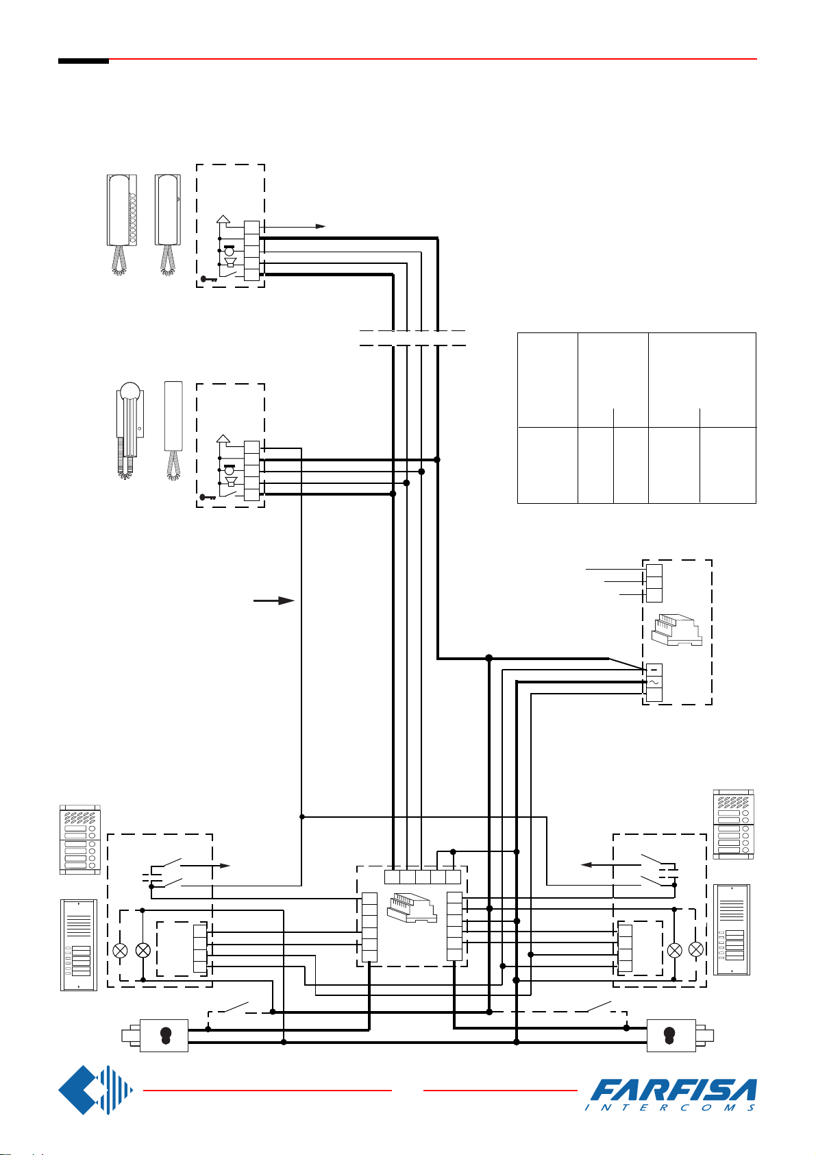
Si 120
INTERCOMS CONNECTED TO TWO DOOR STATIONS WITH AUTOMATIC
SWITCHING.
MEHRFAMILIENHAUS SPRECHANLAGE MIT ZWEI UMSCHALTBAREN
TÜRSTATIONEN.
CT
4 + 1 intercoms
Sprechanlagen 4 + n
PT520
PV100
PT510
924
CT
6
3
1
2
5
6
3
1
2
5
*
xn
CABLE CROSS SECTION
DURCHMESSER VERBINDUNGENSKABEL
distance
in metres
Entfernung
in Meter
50
100
200
300
230V
audio line
and calls
Sprechweg
und
Rufleitungen
mm²
0.25
0.35
0.5
0.75
127V
0
door lock and ground
(cables in bold face type)
Türöffner und Masse
(Fettgedruckte
Leitungen)
mm²
mm
0.5
0,5
1
0,7
2
0,8
2.5
1
AL
mm
0,8
1,2
1,6
1,8
Mody
ErreP/R
" a "
SE
MD
PE
1
2
3
4
PA
+
" b "
MD
xn
98753
6
7a
8a
DS
9a
4
2
1
7b
8b
9b
xn
Mody
1
PE
2
3
4
ErreP/R
PA
SE
25
8 GbD-02
Page 28
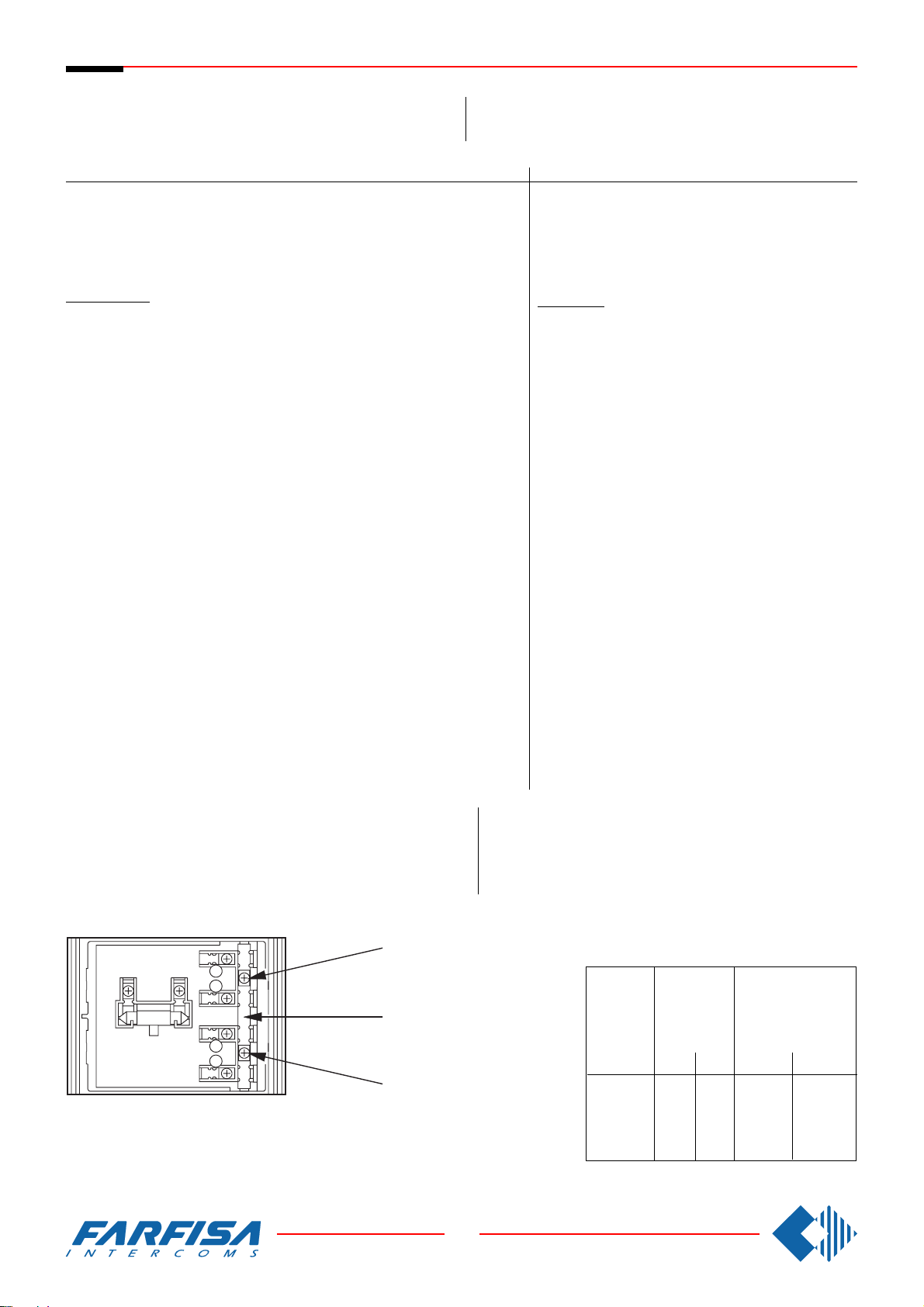
Si 160
INTERCOM SYSTEM WITH ONE MAIN ENTRANCE AND
ADDITIONAL ENTRANCES (RISERS OF BUILDINGS).
MEHRFAMILIENHAUS SPRECHANLAGE MIT NEBENTÜRSTATIONEN UND EINE GEMEINSAME HAUPTTÜRSTATION
(TREPPENHAUSUNTERTEILUNG).
Ref.diagram Q.ty Article Description
Schaltplan Bez.Menge Art.Nr.
CT ... PT510 * Intercom with 1 push-button
AL 1+X PRS220 Power supply
DS X 1473 Exchanger
SE 1+X ** Electric door lock (12VAC-1A)
PA 1+X ** Door release push-button (optional)
Door station
Series Mody (for right item set see on page 10, 11, 12 and 13)
1 row 2 row
MD ... MD71-72-73-74 MD71-72-73-74 Module frames with back box
PE 1+X MD30 MD30 Electric door speaker
Series ErreP/R (see page 15)
MD 1+X RP... Push-button panels
PE 1+X 337-C Electric door speaker
Series TM (see page 14)
MD 1+X T1M1÷T4M60 Push-button panels
PE 1+X 337-C Electric door speaker
... Refers to number of users.
X Refers to the number of stairways.
* Besides the mentioned model all the intercoms from the Project,
PuntoVirgola, 900 and 700 can be installed.
** Articles not supplied by ACI Farfisa.
*** Rain shelters are used instead of back boxes and hood covers.
Einzeltasten Doppeltasten
1+X MD10-11-12 MD10-122-124 Modules for electric door speaker
... MD21÷24 MD222÷228 Button modules
MD20-50 MD20-50 Blank and info modules
1+X MD81÷812 MD81÷812 Hood covers
1+X MD91÷912*** MD91÷912*** Rain shelters with module frames
... R... Push-button panels
1+X 290R2÷38 Rain shelters
1+X 290/101÷460 Rain shelters
Beschreibung
Haustelefon Serie Project
Netzteil
Umschalter
Elektrischer Türöffner (12Vac-1A)
Türöffnungstaste (Zusatztaste)
Türstation
Serie Mody (siehe Seiten 10,11, 12 und 13 für die Zusam-
mensetzung)
Unterputzgehäuse
Türsprechmodul
Ruftastenmodul
Leermodul - Hausnummermodul
Wetterschutzrahmen
Aufputzgehäuse
Türfreisprecheinrichtung
Serie ErreP/R (siehe Seite 15 für die Zusammensetzung)
Türstation
Klingelplatte
Aufputzgehäuse
Türfreisprecheinrichtung
Serie TM (siehe Seite 14 für die Zusammensetzung)
Türstation
Aufputzgehäuse
Türfreisprecheinrichtung
... abhängig von der Anzahl der Teilnehmer.
X abhängig von der Anzahl der Treppenhäuser.
* zes können auch Haustelefone der Serien Project,
PuntoVirgola, 900 und 700 eingesetzt werden.
** diese Teile werden vom Hersteller nicht geliefert.
*** Die Aufputzgehäuse werden anstelle der Unterputz-
gehäuse eingesetzt und haben auch ein Wasserschutzdach.
Note
The push-button panel of the main entrance has to have separate
commons.
Common buttons 1 and 2
Gemeinsamer Eingang Klingeltasten 1 und 2
To separate buttons common
cut here
Trennpunkt der gemeinsame
Anschlußklemme
Common buttons 3 and 4
Gemeinsamer Eingang Klingeltasten 3 und 4
26
8 GbD-02
Bitte beachten:
Bei der Haupttürstation muß der Rufstrom getrennt für jedes
Treppenhaus an den gemeinsamen Eingang der Klingeltasten
angeschlossen werden.
Die Klingeltastenmodule der Serie Mody können nur in Zweiergruppen unterteilt werden.
CABLE CROSS SECTION
DURCHMESSER VERBINDUNGENSKABEL
distance
in metres
Entfernung
in Meter
50
100
200
300
audio line
and calls
Sprechweg
und
Rufleitungen
mm²
0.25
0.35
0.5
0.75
door lock and ground
(cables in bold face type)
Türöffner und Masse
(Fettgedruckte
Leitungen)
mm²
mm
0.5
0,5
1
0,7
2
0,8
2.5
1
mm
0,8
1,2
1,6
1,8
Page 29
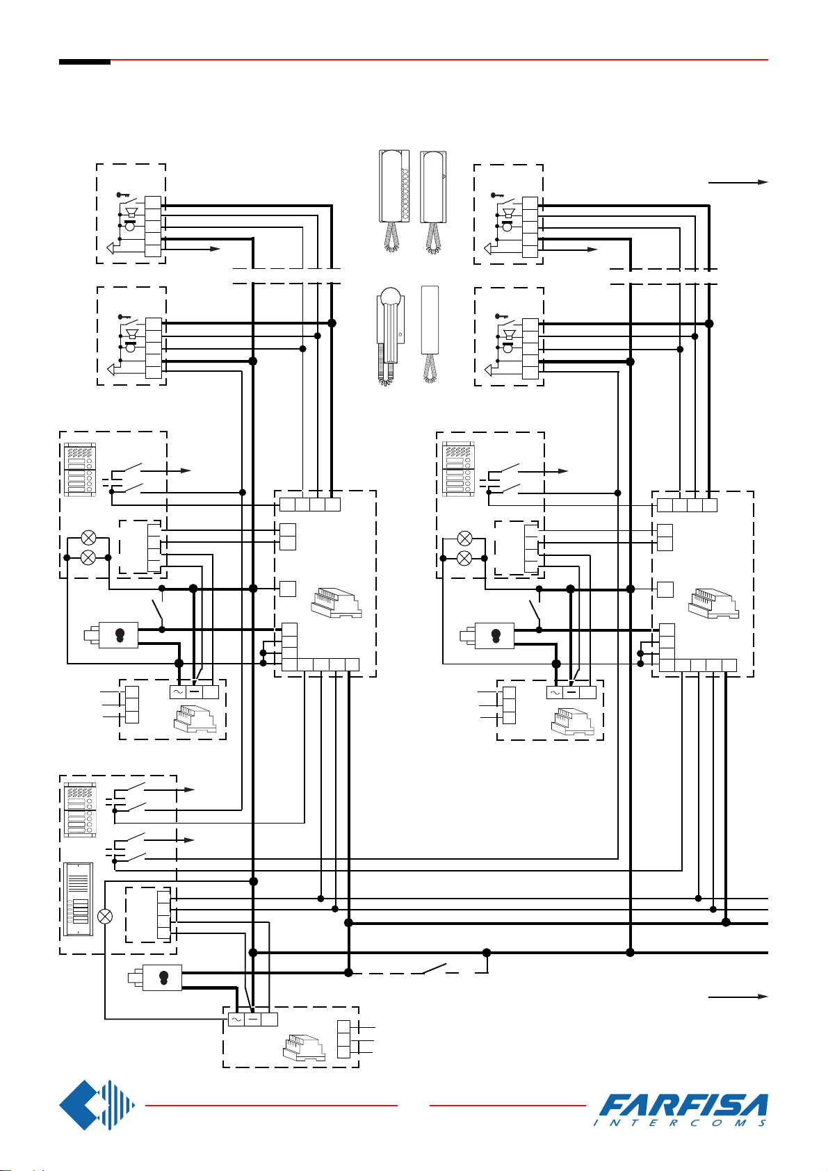
Si 160
4 + 1 intercoms
INTERCOM SYSTEM WITH ONE MAIN ENTRANCE AND ADDITIONAL
Sprechanlagen 4 + n
ENTRANCES (RISERS OF BUILDINGS).
MEHRFAMILIENHAUS SPRECHANLAGE MIT NEBENTÜRSTATIONEN UND EINE GEMEINSAME
HAUPTTÜRSTATION (TREPPENHAUSUNTERTEILUNG).
CT
CT
CT
5
2
1
3
6
xn
PT510
PT520
5
2
1
3
6
CT
5
2
1
3
6
924PV100
5
2
1
3
6
"B""A" "C-D-"
xn
MDMD
xn
xn
Mody
127V
230V
MD
Mody
ErreP/R
SE
0
PE
PA
PE
AL
6789
1
2
3
4
7a
8a
DS
2
Mody
PE
1
2
3
4
6789
7a
8a
DS
2
PA
SE
9a
1
3
4 7b8b9b
5
+
xn (A)
xn (B)
1
2
3
4
0
127V
230V
AL
+
9a
1
3
47b8b9b
5
SE
AL
PA
+
0
127V
230V
"C-D-"
27
8 GbD-02
Page 30
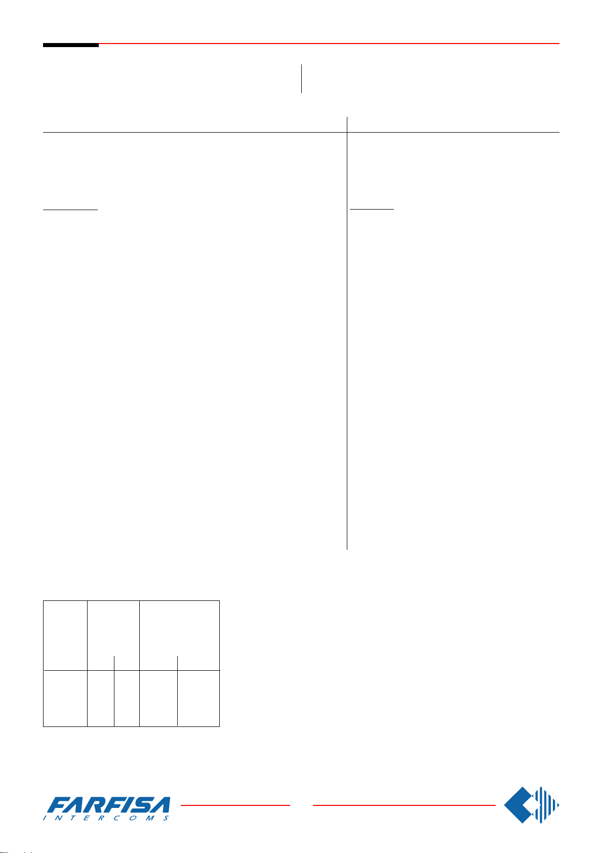
Si 100/EM
INTERCOMS CONNECTED TO A DOOR STATION
WITH ELECTRONIC CALL AND A BUZZER FROM
THE FLOOR.
Ref.diagram Q.ty Article Description
Schaltplan Bez. Menge Art.Nr.
CT ... PT510 * Intercom with 1 push-button
AL 1 PRS240 Power supply
FP .. . ** Floor push-button
SE 1 ** Electric door lock (12VAC-1A)
PA 1 ** Door release push-button (optional)
MEHRFAMILIENHAUS SPRECHANLAGE MIT EINER
TÜRSTATION, ELEKTRONISCHER KLANGRUF UND
ETAGENRUF.
Door station
Series Mody (for right item set see on page 10, 11, 12 and 13)
1 row 2 row
MD ... MD71-72-73-74 MD71-72-73-74 Module frames with back box
PE 1 MD30 MD30 Electric door speaker
Series ErreP/R (see page 15)
MD 1 RP... Push-button panels
PE 1 337-C Electric door speaker
Einzeltasten Doppeltasten
1 MD10-11-12 MD10-122-124 Modules for electric door speaker
... MD21÷24 MD222÷228 Button modules
MD20-50 MD20-50 Blank and info modules
1 MD81÷812 MD81÷812 Hood covers
1 MD91÷912*** MD91÷912*** Rain shelters with module frames
... R... Push-button panels
1 290R2÷38 Rain shelters
Beschreibung
Haustelefon Serie Project
Netzteil
Etagenklingel
Elektrischer Türöffner (12Vac-1A)
Türöffnungstaste (Zusatztaste)
Türstation
Serie Mody (siehe Seiten 10,11, 12 und 13 für die Zusam-
mensetzung)
Unterputzgehäuse
Türsprechmodul
Ruftastenmodul
Leermodul - Hausnummermodul
Wetterschutzrahmen
Aufputzgehäuse
Türfreisprecheinrichtung
Serie ErreP/R (siehe Seite 15 für die Zusammensetzung)
Türstation
Klingelplatte
Aufputzgehäuse
Türfreisprecheinrichtung
Series TM (see page 14)
MD 1 T1M1÷T4M60 Push-button panels
PE 1 337-C Electric door speaker
... Refers to number of users.
* Besides the mentioned model all the intercoms from the Project,
PuntoVirgola and 900 can be installed.
** Articles not supplied by ACI Farfisa.
*** Rain shelters are used instead of back boxes and hood covers.
Working instructions: see page 19.
CABLE CROSS SECTION
DURCHMESSER VERBINDUNGENSKABEL
distance
in metres
Entfernung
in Meter
50
100
200
300
1 290/101÷460 Rain shelters
audio line
and calls
Sprechweg
und
Rufleitungen
mm²
0.25
0.35
0.5
0.75
door lock and ground
(cables in bold face type)
Türöffner und Masse
(Fettgedruckte
Leitungen)
mm²
mm
0.5
0,5
1
0,7
2
0,8
2.5
1
mm
0,8
1,2
1,6
1,8
Serie TM (siehe Seite 14 für die Zusammensetzung)
Türstation
Aufputzgehäuse
Türfreisprecheinrichtung
... abhängig von der Anzahl der Teilnehmer.
* es können auch Haustelefone der Serien Project,
PuntoVirgola und 900 eingesetzt werden.
** diese Teile werden vom Hersteller nicht geliefert.
*** Die Aufputzgehäuse werden anstelle der Unterputz-
gehäuse eingesetzt und haben auch ein Wasser-
schutzdach.
Funktionsbeschrelbung: Siehe Seite 20.
28
8 GbD-02
Page 31
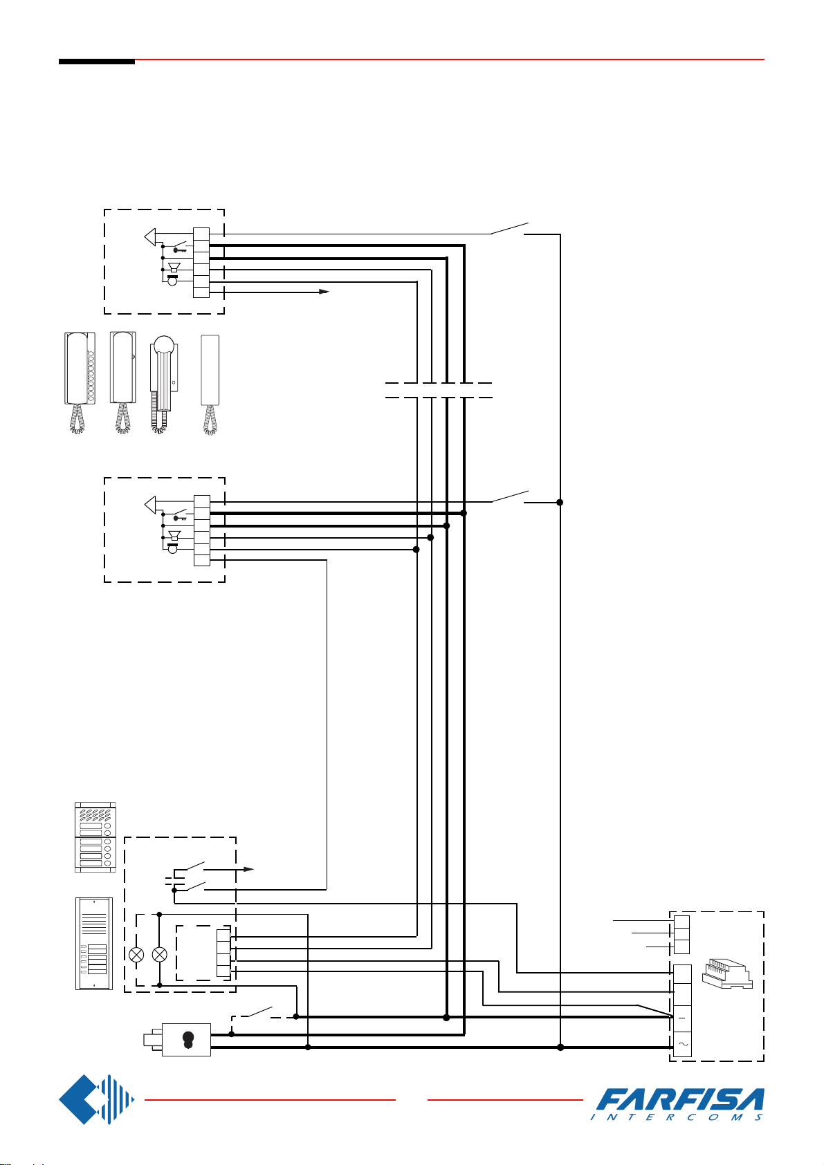
Si 100/EM
INTERCOMS CONNECTED TO A DOOR STATION WITH ELECTRONIC
CALL AND A BUZZER FROM THE FLOOR.
MEHRFAMILIENHAUS SPRECHANLAGE MIT EINER TÜRSTATION,
ELEKTRONISCHER KLANGRUF UND ETAGENRUF.
4 + 1 intercoms
Sprechanlagen 4 + n
(mit elektronischem Klangruf)
CT
CT
6
5
3
2
1
9
PV100PT510 924PT520
6
5
3
2
1
9
xn
FP
FP
Mody
ErreP/R
SE
PE
MD
PA
xn
230V
1
2
3
4
127V
0
AL
C+
+
29
8 GbD-02
Page 32
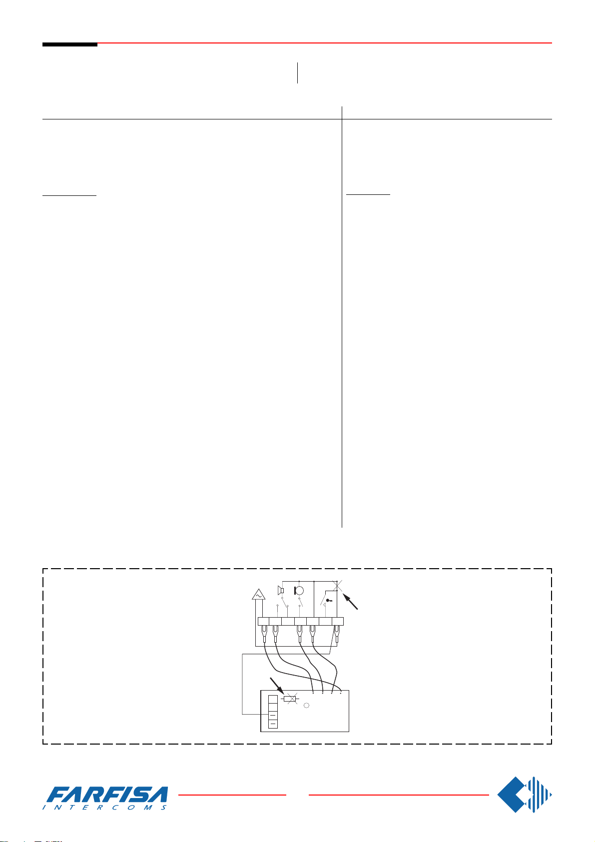
Si 100/SM
INTERCOMS WITH PRIVATE CONVERSATION MODULE CONNECTED TO A DOOR STATION.
Ref.diagram Q.ty Article Description
MEHRFAMILIENHAUS SPRECHANLAGE MIT EINER
TÜRSTATION UND MITHÖRSPERRE.
Schaltplan Bez. Menge Art.Nr.
CT ... PT510 * Intercom with 1 push-button
SM ... SM50 Private conversation module
AL 1 PRS235 Power supply
SE 1 ** Electric door lock (12VAC-1A)
PA 1 ** Door release push-button (optional)
Door station
Series Mody (for right item set see on page 10, 11, 12 and 13)
1 row 2 row
MD ... MD71-72-73-74 MD71-72-73-74 Module frames with back box
PE 1 MD30 MD30 Electric door speaker
Series ErreP/R (see page 15)
MD 1 RP... Push-button panels
PE 1 337-C Electric door speaker
Einzeltasten Doppeltasten
1 MD10-11-12 MD10-122-124 Modules for electric door speaker
... MD21÷24 MD222÷228 Button modules
MD20-50 MD20-50 Blank and info modules
1 MD81÷812 MD81÷812 Hood covers
1 MD91÷912*** MD91÷912*** Rain shelters with module frames
... R... Push-button panels
1 290R2÷38 Rain shelters
Beschreibung
Haustelefon Serie Project
Mithörsperrmodul
Netzteil
Elektrischer Türöffner (12Vac-1A)
Türöffnungstaste (Zusatztaste)
Türstation
Serie Mody (siehe Seiten 10,11, 12 und 13 für die Zusam-
mensetzung)
Unterputzgehäuse
Türsprechmodul
Ruftastenmodul
Leermodul - Hausnummermodul
Wetterschutzrahmen
Aufputzgehäuse
Türfreisprecheinrichtung
Serie ErreP/R (siehe Seite 15 für die Zusammensetzung)
Türstation
Klingelplatte
Aufputzgehäuse
Türfreisprecheinrichtung
Series TM (see page 14)
MD 1 T1M1÷T4M60 Push-button panels
PE 1 337-C Electric door speaker
... Refers to number of users.
* Besides the mentioned model all the intercoms from the Project series
can be installed.
** Articles not supplied by ACI Farfisa.
*** Rain shelters are used instead of back boxes and hood covers.
Working instructions: see page 19.
1 290/101÷460 Rain shelters
Intercoms Project series
In each intercom it is necessary:
- to cut the jumper (W1) that links the terminals 3 and
7;
- to move the connection of the buzzer from terminal
3 to 7;
- to activate the connection between terminal 7 of the
intercom and the - (minus) of the private conversation
module.
In all private conversation modules cut the resist-
ance R1.
62 91357
10K
C
R1
B
W1
2136
Serie TM (siehe Seite 14 für die Zusammensetzung)
Türstation
Aufputzgehäuse
Türfreisprecheinrichtung
... abhängig von der Anzahl der Teilnehmer.
* es können auch Haustelefone der Serie Project einge-
setzt werden.
** diese Teile werden vom Hersteller nicht geliefert.
*** Die Aufputzgehäuse werden anstelle der Unterputz-
gehäuse eingesetzt und haben auch ein Wasser-
schutzdach.
Funktionsbeschrelbung: Siehe Seite 20.
Haustelefone Serie Project
In jedem Haustelefon muß man:
- die Drahtbrücke (W1) unterbrechen, um die Anschlußklemmen 3 und 7 zu trennen;
- die Drahtbrücke des Summers von der Anschluß-
klemme 3 auf 7 versetzen;
- die Verbindung zwischen Anschlußklemme 7 des
Haustelefons und der Anschlußklemme - (minus)
des Mithörsperrmoduls einsetzen.
In allen Mithörsperrmodulen den Wiederstand R1
trennen.
30
8 GbD-02
SM 50
Page 33
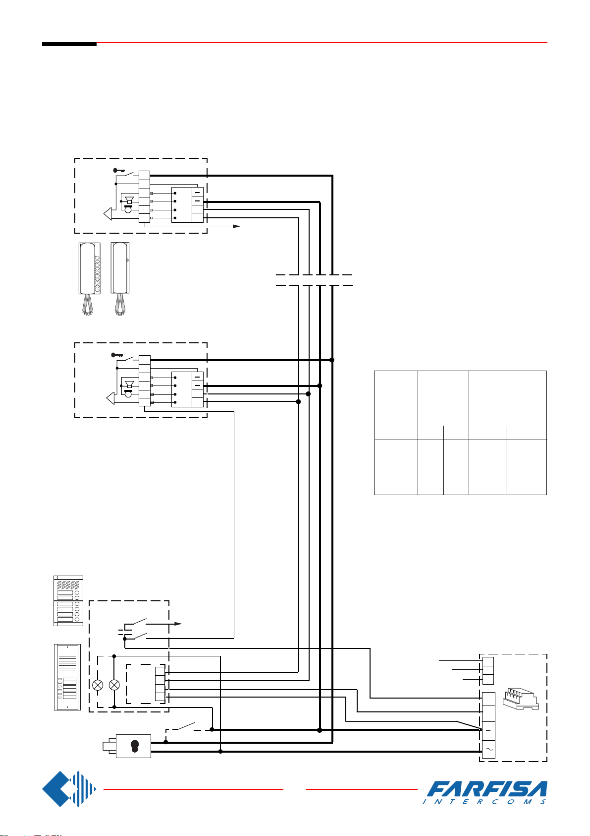
Si 100/SM
INTERCOMS WITH PRIVATE CONVERSATION MODULE CONNECTED
TO A DOOR STATION.
MEHRFAMILIENHAUS SPRECHANLAGE MIT EINER TÜRSTATION UND
MITHÖRSPERRE.
4 + 1 intercoms
Sprechanlagen 4 + n
(mit Mithörsperre)
CT
+ SM
PT520
CT
+ SM
PT510
5
7
3
2
1
6
5
7
3
2
1
6
3
2
C
1
B
6
3
2
C
1
B
6
xn
CABLE CROSS SECTION
DURCHMESSER VERBINDUNGENSKABEL
distance
in metres
Entfernung
in Meter
50
100
200
300
audio line
and calls
Sprechweg
und
Rufleitungen
mm²
0.25
0.35
0.5
0.75
door lock and ground
(cables in bold face type)
Türöffner und Masse
(Fettgedruckte
Leitungen)
mm²
mm
0.5
0,5
1
0,7
2
0,8
2.5
1
mm
0,8
1,2
1,6
1,8
Mody
ErreP/R
SE
PE
MD
PA
xn
230V
1
2
3
4
127V
0
AL
C+
+
31
8 GbD-02
Page 34
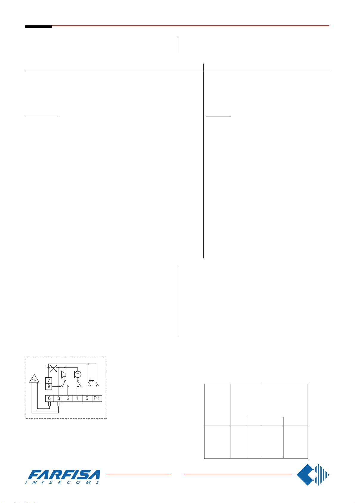
Si 210/5
5 INTERCOMMUNICATING INTERCOMS CONNECTED
TO A DOOR STATION WITH INDIVIDUAL CALL.
MEHRFAMILlENHAUS-SPRECHANLAGE MIT 5 HAUSTELEFONE, EINER TÜRSTATION UND INTERNEN GEGENSPRECHVERKEHR.
Ref.diagram Q.ty Article Description
Schaltplan Bez. Menge Art.Nr.
CT ... PT520 Intercom with 2 push-buttons
SP ... PT501 Individual push-button unit
AL 1 PRS226 Power supply/switcher
SE 1 ** Electric door lock (12VAC-1A)
PA 1 ** Door release push-button (optional)
Door station
Series Mody (for right item set see on page 10, 11, 12 and 13)
1 row 2 row
MD ... MD71-72-73 MD71-72-73 Module frames with back box
PE 1 MD30 MD30 Electric door speaker
Series ErreP/R (see page 15)
MD 1 RP... Push-button panels
PE 1 337-C Electric door speaker
Einzeltasten Doppeltasten
1 MD10-11-12 MD10-122-124 Modules for electric door speaker
... MD21÷24 MD222÷228 Button modules
MD20-50 MD20-50 Blank and info modules
1 MD81÷84 MD81÷84 Hood covers
1 MD91÷94*** MD91÷94*** Rain shelters with module frames
... R... Push-button panels
1 290R2÷22 Rain shelters
Beschreibung
Haustelefon mit 2 Tasten
Zusatztaste
Netzteil
Elektrischer Türöffner (12Vac-1A)
Türöffnungstaste (Zusatztaste)
Türstation
Serie Mody (siehe Seiten 10,11, 12 und 13 für die Zusam-
mensetzung)
Unterputzgehäuse
Türsprechmodul
Ruftastenmodul
Leermodul - Hausnummermodul
Wetterschutzrahmen
Aufputzgehäuse
Türfreisprecheinrichtung
Serie ErreP/R (siehe Seite 15 für die Zusammensetzung)
Türstation
Klingelplatte
Aufputzgehäuse
Türfreisprecheinrichtung
Series TM (see page 14)
MD 1 T1M1÷T2M10 Push-button panels
1 290/101÷210 Rain shelters
PE 1 337-C Electric door speaker
... Refers to number of users.
** Articles not supplied by ACI Farfisa.
*** Rain shelters are used instead of back boxes and hood covers.
Working instructions: see page 19.
Note
In each intercom remove the jumper W1 that links terminals 3 and 7.
For a different number of intercoms see the application diagrams on
page 40.
W1
1
PT 520
Serie TM (siehe Seite 14 für die Zusammensetzung)
Türstation
Aufputzgehäuse
Türfreisprecheinrichtung
... abhängig von der Anzahl der Teilnehmer.
** diese Teile werden vom Hersteller nicht geliefert.
*** Die Aufputzgehäuse werden anstelle der Unterputzgehäuse einge-
setzt und haben auch ein Wasserschutzdach.
Funktionsbeschrelbung: Siehe Seite 20.
Bitte beachten
In jedem Haustelefon muß man die Drahtbrücke (W1) zwischen den
Anschlußklemmen 3 und 7 unterbrechen.
Für eine unterschiedliche Anzahl von Haustelefone bitte Anwendungsschaltpläne auf der Seite 40 beachten.
CABLE CROSS SECTION
DURCHMESSER VERBINDUNGENSKABEL
distance
in metres
Entfernung
in Meter
audio line
and calls
Sprechweg
und
Rufleitungen
mm²
door lock and ground
(cables in bold face type)
Türöffner und Masse
(Fettgedruckte
Leitungen)
mm²
mm
mm
32
8 GbD-02
50
100
200
300
0.25
0.35
0.5
0.75
0,5
0,7
0,8
1
0.5
1
2
2.5
0,8
1,2
1,6
1,8
Page 35
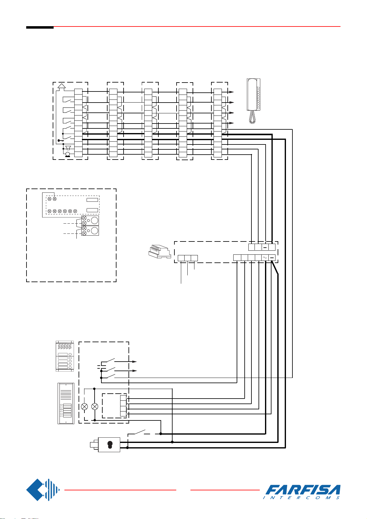
Si 210/5
9 7
2315P16
P2
P3
5 INTERCOMMUNICATING INTERCOMS CONNECTED TO A DOOR STATION
WITH INDIVIDUAL CALL.
MEHRFAMILlENHAUS SPRECHANLAGE MIT 5 HAUSTELEFONE, EINER
TÜRSTATION UND INTERNEN GEGENSPRECHVERKEHR.
Intercommunicating
Gegensprechanlagen
6
4
P4
3
P3
2
P2
P1
1
7
5
3
2
1
CT5
+SP
CT4
+SP
In all intercoms connect one of the two
terminals of the single button unit to
terminal 7.
In allen Haustelefonen muß eine der
Anschlußklemmen der Zusatztasten mit
der Klemme 7 verbunden werden.
P4
P3
P2
P1
P3
6
7
5
3
2
1
P4
6
P2
P1
7
5
3
2
1
CT3
+SP
P2
P4
P3
6
P1
7
5
3
2
1
CT2
+SP
P1
P4
P3
P2
CT1
+SP
AL
0
127V
230V
xn
x4
x3
x2
6
7
5
3
2
1
G2 7
AD
C+
+
MD
xn
Mody
PE
ErreP/R
SE
x2
1
2
3
4
PA
33
8 GbD-02
Page 36
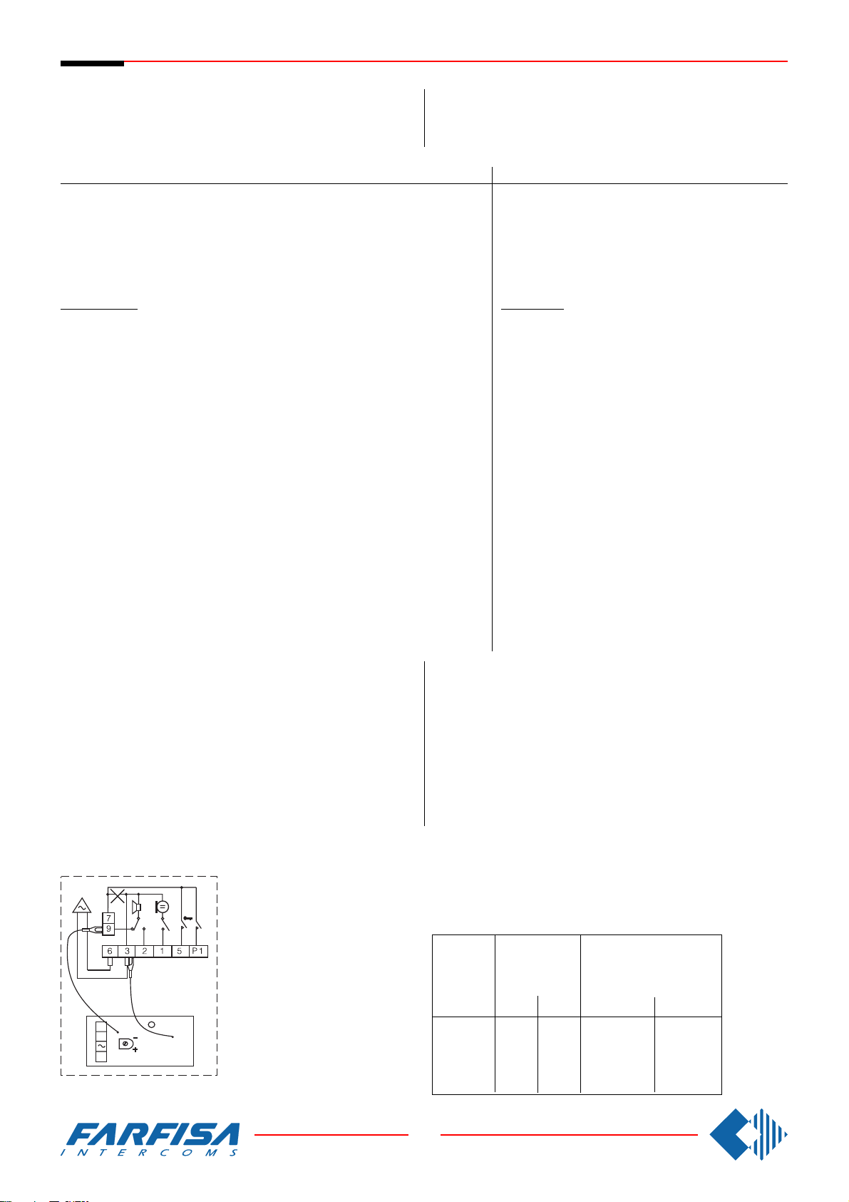
Si 220/5
5 INTERCOMMUNICATING INTERCOMS CONNECTED
TO A DOOR STATION WITH INDIVIDUAL CALL AND
ELECTRONIC BELL FOR INTERNAL CALLS.
MEHRFAMILlENHAUS SPRECHANLAGE MIT 5 HAUSTELEFONE, EINER TÜRSTATION UND INTERNEN GEGENSPRECHVERKEHR MlT ELEKTRONISCHEM
KLANGRUF FÜR INTERNRUFE.
Ref.diagram Q.ty Article Description
Schaltplan Bez. Menge Art.Nr.
CT ... PT520 Intercom with 2 push-buttons
SP ... PT501 Individual push-button unit
RS ... SR40 Electronic bell module
AL 1 PRS226 Power supply/switcher
SE 1 ** Electric door lock (12VAC-1A)
PA 1 ** Door release push-button (optional)
Door station
Series Mody (for right item set see on page 10, 11, 12 and 13)
MD ... MD71-72-73 MD71-72-73 Module frames with back box
PE 1 MD30 MD30 Electric door speaker
Series ErreP/R (see page 15)
1 row 2 row
Einzeltasten Doppeltasten
1 MD10-11-12 MD10-122-124 Modules for electric door speaker
... MD21÷24 MD222÷228 Button modules
MD20-50 MD20-50 Blank and info modules
1 MD81÷84 MD81÷84 Hood covers
1 MD91÷94*** MD91÷94*** Rain shelters with module frames
Beschreibung
Haustelefon mit 2 Tasten
Zusatztaste
Klangrufmodul
Netzteil
Elektrischer Türöffner (12Vac-1A)
Türöffnungstaste (Zusatztaste)
Türstation
Serie Mody (siehe Seiten 10,11, 12 und 13 für die Zusam-
mensetzung)
Unterputzgehäuse
Türsprechmodul
Ruftastenmodul
Leermodul - Hausnummermodul
Wetterschutzrahmen
Aufputzgehäuse
Türfreisprecheinrichtung
Serie ErreP/R (siehe Seite 15 für die Zusammensetzung)
MD 1 RP... Push-button panels
PE 1 337-C Electric door speaker
Series TM (see page 14)
MD 1 T1M1÷T2M10 Push-button panels
PE 1 337-C Electric door speaker
... Refers to number of users.
** Articles not supplied by ACI Farfisa.
*** Rain shelters are used instead of back boxes and hood covers.
Working instructions: see page 19.
Note
In each intercom remove the jumper W1 that links terminals 3 and 7.
For a different number of intercoms see the application diagrams on page
41.
... R... Push-button panels
1 290R2÷22 Rain shelters
1 290/101÷210 Rain shelters
W1
1
PT 520
9
X1
X2
7
SR 40
Türstation
Klingelplatte
Aufputzgehäuse
Türfreisprecheinrichtung
Serie TM (siehe Seite 14 für die Zusammensetzung)
Türstation
Aufputzgehäuse
Türfreisprecheinrichtung
... abhängig von der Anzahl der Teilnehmer.
** diese Teile werden vom Hersteller nicht geliefert.
*** Die Aufputzgehäuse werden anstelle der Unterputzgehäuse einge-
setzt und haben auch ein Wasserschutzdach.
Funktionsbeschrelbung: Siehe Seite 20.
Bitte beachten
In jedem Haustelefon muß man die Drahtbrücke (W1) zwischen den
Anschlußklemmen 3 und 7 unterbrechen.
Für eine unterschiedliche Anzahl von Haustelefone bitte Anwendungsschaltpläne auf der Seite 41 beachten.
CABLE CROSS SECTION
DURCHMESSER VERBINDUNGENSKABEL
distance
in metres
Entfernung
in Meter
50
100
200
300
audio line and
calls
Sprechweg und
Rufleitungen
mm²
0.25
0.35
0.5
0.75
mm
0,5
0,7
0,8
1
door lock and ground
(cables in bold face type)
Türöffner und Masse
(Fettgedruckte Leitungen)
mm²
0.5
1
2
2.5
mm
0,8
1,2
1,6
1,8
34
8 GbD-02
Page 37
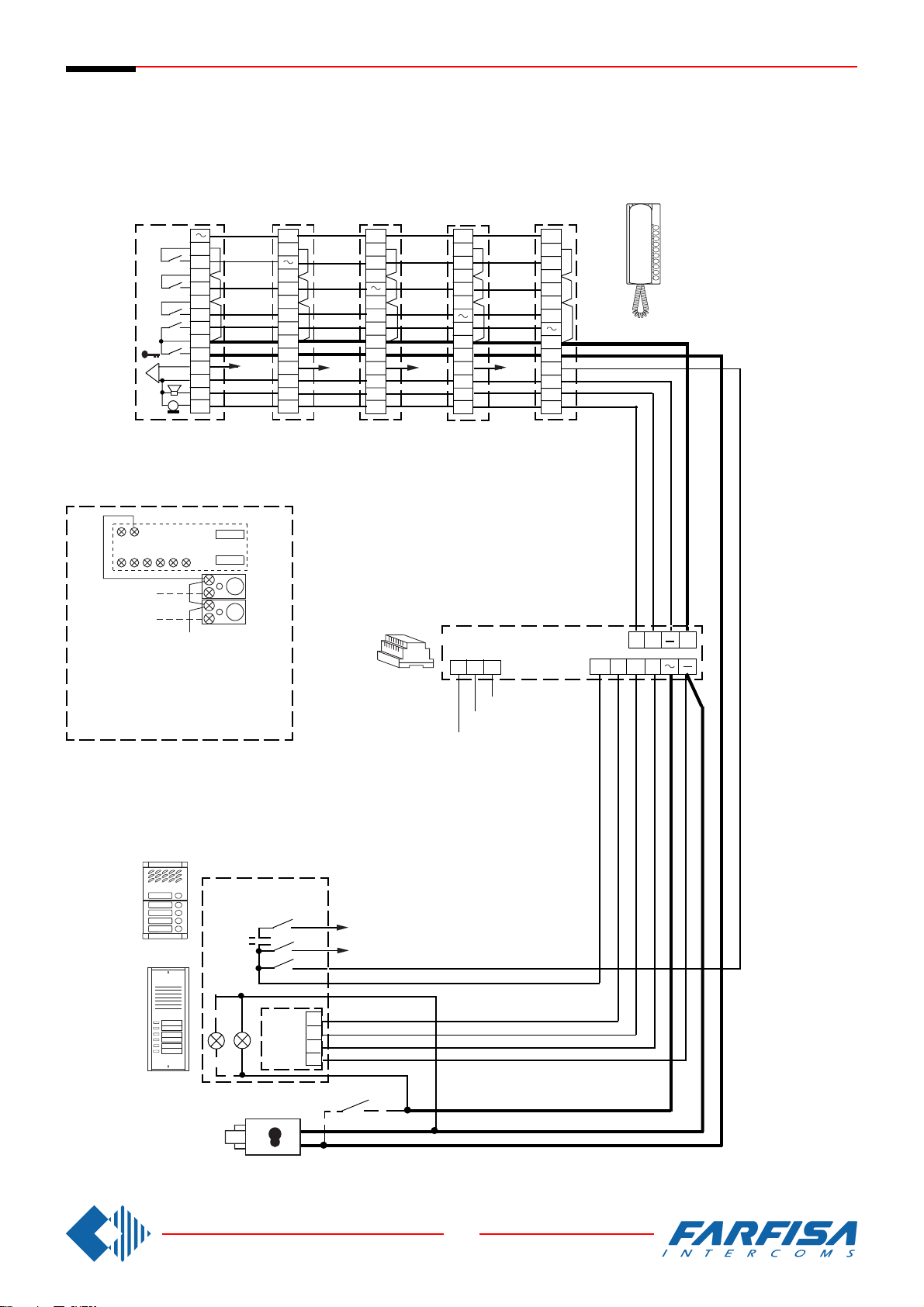
Si 220/5
Intercommunicating
Gegensprechanlagen
5 INTERCOMMUNICATING INTERCOMS CONNECTED TO A DOOR STATION
WITH INDIVIDUAL CALL AND ELECTRONIC BELL FOR INTERNAL CALLS.
MEHRFAMILlENHAUS SPRECHANLAGE MIT 5 HAUSTELEFONE, EINER TÜRSTATION
UND INTERNEN GEGENSPRECHVERKEHR MlT ELEKTRONISCHEM KLANGRUF FÜR
INTERNRUFE.
4
P4
3
P3
2
P2
1
P1
7
5
xn
6
3
2
1
9 7
CT5
+SP
+RS
2315P16
CT4
+SP
+RS
P2
P3
In all intercoms connect one of the two
terminals of the single button unit to
terminal 7.
In allen Haustelefonen muß eine der
Anschlußklemmen der Zusatztasten mit
der Klemme 7 verbunden werden.
P4
P3
P2
P1
P3
P4
P2
7
5
6
3
2
1
P1
7
5
x4
6
3
2
1
CT3
+SP
+RS
P2
P4
P3
P1
7
5
x3
6
3
2
1
CT2
+SP
+RS
AL
0
127V
230V
P1
P4
P3
P2
7
5
x2
6
3
2
1
CT1
+SP
+RS
G2 7
C+
AD
+
Mody
ErreP/R
MD
SE
PE
xn
x2
1
2
3
4
PA
35
8 GbD-02
Page 38
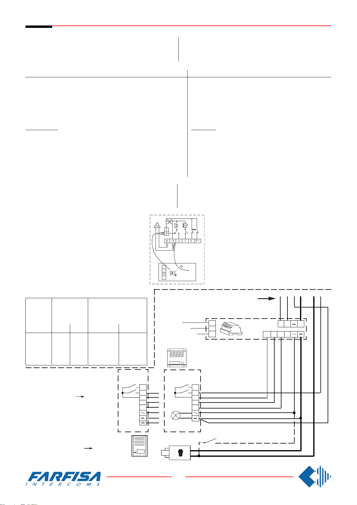
Si 230/5
5 INTERCOMMUNICATING INTERCOMS CONNECTED
TO A DOOR STATION WITH COMMON CALL AND
ELECTRONIC BELL FOR INTERNAL CALLS.
Ref.diagram Q.ty Article Description
Schaltplan Bez. Menge Art.Nr.
CT ... PT520 Intercom with 2 push-buttons
SP ... PT501 Individual push-button unit
RS ... SR40 Electronic bell module
AL 1 PRS226 Power supply/switcher
SE 1 ** Electric door lock (12VAC-1A)
PA 1 ** Door release push-button (optional)
Door station
Series Mody
MD ... MD71 Module frames with back box
1 MD11 Module for electric door speaker
1 MD81 Hood cover
1 MD91*** Rain shelter with module frames
PE 1 MD30 Electric door speaker
... Refers to number of users.
** Articles not supplied by ACI Farfisa.
*** Rain shelters are used instead of back boxes and hood covers.
For other kinds of panels see on page 14 and 15.
ElNFAMILIENHAUS SPRECHANLAGE MIT 5 HAUSTELEFONE, EINER TÜRSTATION UND INTERNEN GEGENSPRECHVERKEHR MIT ELEKTRONISCHEM
KLANGRUF FÜR INTERNRUFE.
Beschreibung
Haustelefon mit 2 Tasten
Zusatztaste
Klangrufmodul
Netzteil
Elektrischer Türöffner (12Vac-1A)
Türöffnungstaste (Zusatztaste)
Türstation
Série Mody
Unterputzgehäuse
Module predisposé pour le Türfreisprecheinrichtung
Wetterschutzrahmen
Aufputzgehäuse
Türfreisprecheinrichtung
... abhängig von der Anzahl der Teilnehmer.
** diese Teile werden vom Hersteller nicht geliefert.
*** Die Aufputzgehäuse werden anstelle der Unterputzgehäuse einge-
setzt und haben auch ein Wasserschutzdach.
Working instructions: see page 19.
Note
In each intercom remove the jumper W1 that links terminals 3 and 7.
For a different number of intercoms see the application
diagrams on page 42.
CABLE CROSS SECTION
DURCHMESSER VERBINDUNGENSKABEL
distance
in metres
Entfernung
in Meter
50
100
200
300
For one family systems the amplified door
stations MD100, RP100, UP100 or UP11
can be installed. In this case superimpose
the actual diagram over that on page 37
laying it out at the riser
In the amplified door station RP100 it is
necessary to cut the jumper W1.
audio line and
calls
Sprechweg und
Rufleitungen
mm²
0.25
0.35
0.5
0.75
mm
0,5
0,7
0,8
1
*
door lock and ground
(cables in bold face type)
Türöffner und Masse
(Fettgedruckte Leitungen)
mm²
0.5
1
2
2.5
RP100
.
mm
0,8
1,2
1,6
1,8
P2
P1
C
W1
PT 520
9
X1
X2
7
SR 40
Funktionsbeschrelbung: Siehe Seite 20.
Bitte beachten
1
In jedem Haustelefon muß man die Drahtbrücke (W1)
zwischen den Anschlußklemmen 3 und 7 unterbrechen.
Für eine unterschiedliche Anzahl von Haustelefone bitte
Anwendungsschaltpläne auf der Seite 42 beachten.
*
230V
127V
0
PRS226
MD100
MD71
1
2
C
1
2
AD
G2 7
C+
+
Für Einfamilienhausanlagen kann auch
die Türstation mit eingebauter Türfreisprecheinrichtung MD100, RP100, UP100
oder UP11 eingesetzt werden. In diesem
Fall setzen Sie diesen Schaltplan auf den
nebenan bündig mit dem
zeichneten Trennpunkt.
In den Türstation RP100 muß die Draht-
brücke W1 getrennt werden.
*
gekenn-
SE
36
8 GbD-02
PA
Page 39
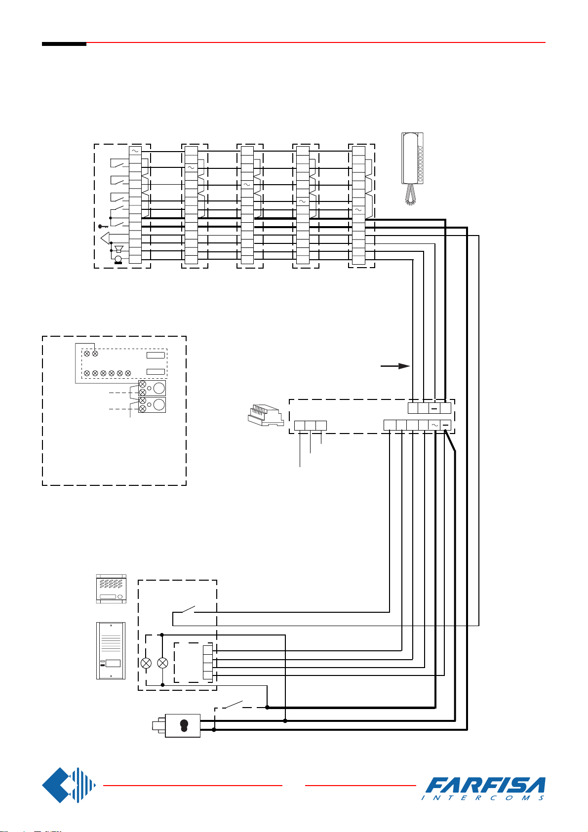
Si 230/5
9 7
2315P16
P2
P3
Intercommunicating
Gegensprechanlagen
5 INTERCOMMUNICATING INTERCOMS CONNECTED TO A DOOR STATION
WITH COMMON CALL AND ELECTRONIC BELL FOR INTERNAL CALLS.
ElNFAMILIENHAUS SPRECHANLAGE MIT 5 HAUSTELEFONE, EINER TÜRSTATION UND
INTERNEN GEGENSPRECHVERKEHR MIT ELEKTRONISCHEM KLANGRUF FÜR INTERNRUFE.
4
P4
3
P3
2
P2
P1
1
7
5
6
3
2
1
CT5
+SP
+RS
In all intercoms connect one of the two
terminals of the single button unit to
terminal 7.
In allen Haustelefonen muß eine der
Anschlußklemmen der Zusatztasten mit
der Klemme 7 verbunden werden.
P4
P3
P2
P1
7
5
6
3
2
1
CT4
+SP
+RS
P3
P4
P2
P1
7
5
6
3
2
1
CT3
+SP
+RS
P2
P4
P3
P1
CT2
+SP
+RS
AL
230V
7
5
6
3
2
1
127V
P1
P4
P3
P2
7
5
6
3
2
1
CT1
+SP
+RS
*
G2 7
C+
AD
0
+
MD
Mody
1
PE
2
3
4
ErreP/R
SE
PA
37
8 GbD-02
Page 40
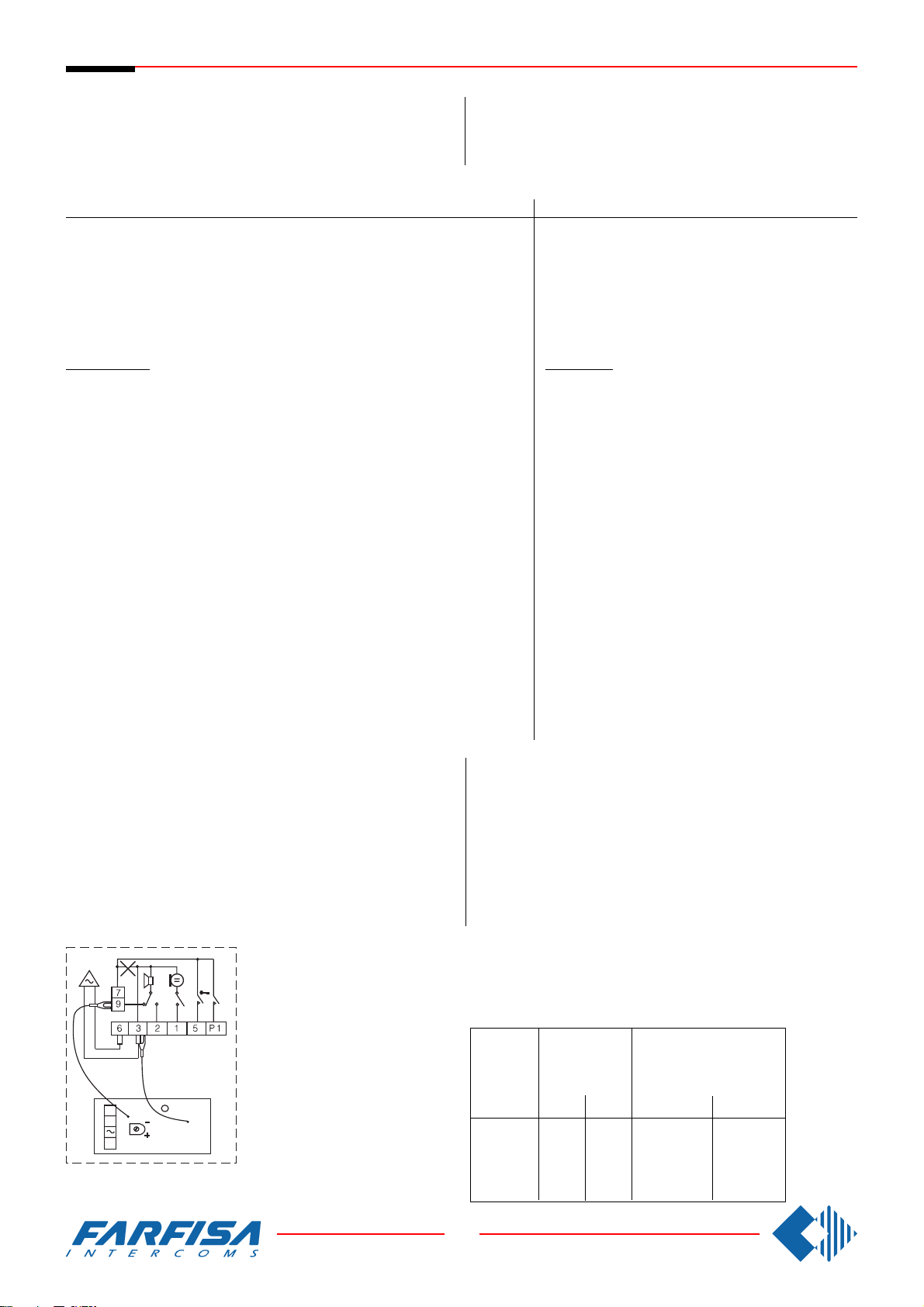
Si 250/5
5 INTERCOMMUNICATING INTERCOMS CONNECTED
TO TWO DOOR STATIONS WITH AUTOMATIC
SWITCHING AND WITH INDIVIDUAL CALL. ELECTRONIC BELL FOR INTERNAL CALLS.
Ref.diagram Q.ty Article Description
Schaltplan Bez. Menge Art.Nr.
CT ... PT520 Intercom with 2 push-buttons
SP ... PT501 Individual push-button unit
RS ... SR40 Electronic bell module
AL 1 PRS226 Power supply/switcher
DS 1 1473 Exchanger
SE 2 ** Electric door lock (12VAC-1A)
PA 2 ** Door release push-button (optional)
MEHRFAMILIENHAUS SPRECHANLAGE MIT 5 HAUSTELEFONE, 2 UMSCHALTBARE TÜRSTATIONEN UND
INTERNEN GEGENSPRECHVERKEHR MIT ELEKTRONISCHEM KLANGRUF FÜR INTERNRUFE.
Door station
Series Mody (for right item set see on page 10, 11, 12 and 13)
MD ... MD71-72-73 MD71-72-73 Module frames with back box
PE 2 MD30 MD30 Electric door speaker
1 row 2 row
Einzeltasten Doppeltasten
2 MD10-11-12 MD10-122-124 Modules for electric door speaker
... MD21÷24 MD222÷228 Button modules
MD20-50 MD20-50 Blank and info modules
2 MD81÷84 MD81÷84 Hood covers
2 MD91÷94*** MD91÷94*** Rain shelters with module frames
Beschreibung
Haustelefon mit 2 Tasten
Zusatztaste
Klangrufmodul
Netzteil
Umschalter
Elektrischer Türöffner (12Vac-1A)
Türöffnungstaste (Zusatztaste)
Türstation
Serie Mody (siehe Seiten 10,11, 12 und 13 für die Zusam-
mensetzung)
Unterputzgehäuse
Türsprechmodul
Ruftastenmodul
Leermodul - Hausnummermodul
Wetterschutzrahmen
Aufputzgehäuse
Türfreisprecheinrichtung
Series ErreP/R (see page 15)
MD 2 RP... Push-button panels
PE 2 337-C Electric door speaker
Series TM (see page 14)
MD 2 T1M1÷T2M10 Push-button panels
PE 2 337-C Electric door speaker
... Refers to number of users.
** Articles not supplied by ACI Farfisa.
*** Rain shelters are used instead of back boxes and hood covers.
Working instructions: see page 19.
Note
In each intercom remove the jumper W1 that links terminals 3 and 7.
For a different number of intercoms see the application diagrams on page
41.
... R... Push-button panels
2 290R2÷22 Rain shelters
2 290/101÷210 Rain shelters
W1
1
PT 520
9
X1
X2
7
SR 40
Serie ErreP/R (siehe Seite 15 für die Zusammensetzung)
Türstation
Klingelplatte
Aufputzgehäuse
Türfreisprecheinrichtung
Serie TM (siehe Seite 14 für die Zusammensetzung)
Türstation
Aufputzgehäuse
Türfreisprecheinrichtung
... abhängig von der Anzahl der Teilnehmer.
** diese Teile werden vom Hersteller nicht geliefert.
*** Die Aufputzgehäuse werden anstelle der Unterputzgehäuse einge-
setzt und haben auch ein Wasserschutzdach.
Funktionsbeschrelbung: Siehe Seite 20.
Bitte beachten
In jedem Haustelefon muß man die Drahtbrücke (W1) zwischen den
Anschlußklemmen 3 und 7 unterbrechen.
Für eine unterschiedliche Anzahl von Haustelefone bitte Anwendungsschaltpläne auf der Seite 41 beachten.
CABLE CROSS SECTION
DURCHMESSER VERBINDUNGENSKABEL
distance
in metres
Entfernung
in meters
50
100
200
300
audio line and
calls
Sprechweg und
Rufleitungen
mm²
0.25
0.35
0.5
0.75
mm
0,5
0,7
0,8
1
door lock and ground
(cables in bold face type)
Türöffner und Masse
(Fettgedruckte Leitungen)
mm²
0.5
1
2
2.5
mm
0,8
1,2
1,6
1,8
38
8 GbD-02
Page 41
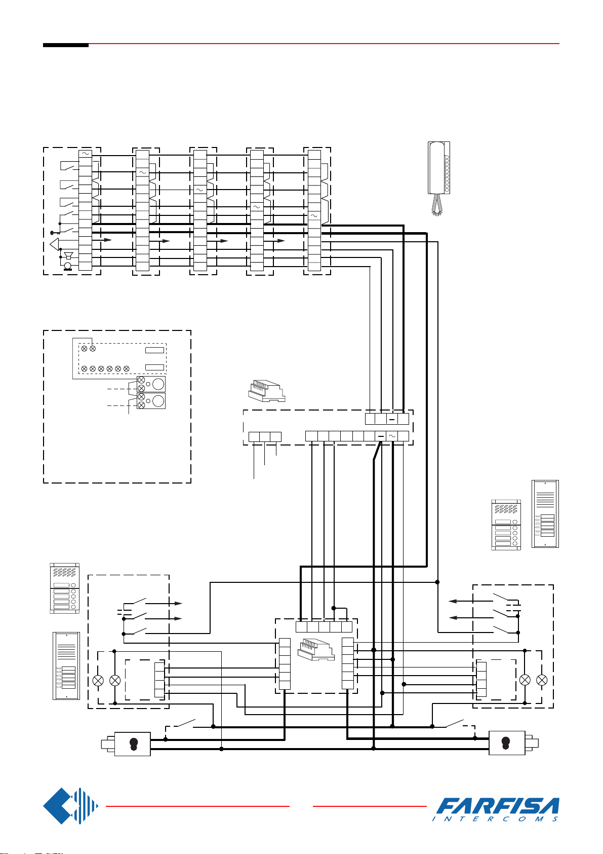
Si 250/5
9 7
2315P16
P2
P3
Intercommunicating
Gegensprechanlagen
5 INTERCOMMUNICATING INTERCOMS CONNECTED TO TWO DOOR
STATIONS WITH AUTOMATIC SWITCHING AND WITH INDIVIDUAL CALL.
ELECTRONIC BELL FOR INTERNAL CALLS.
MEHRFAMILIENHAUS SPRECHANLAGE MIT 5 HAUSTELEFONE, 2 UMSCHALTBARE TÜRSTATIONEN UND INTERNEN GEGENSPRECHVERKEHR MIT ELEKTRONISCHEM KLANGRUF FÜR INTERNRUFE.
P4
4
P4
3
P3
2
P2
P1
1
7
5
6
3
2
1
CT5
+SP
+RS
P3
P2
P1
7
5
xn
6
3
2
1
x4
CT4
+SP
+RS
In all intercoms connect one of the two
terminals of the single button unit to
terminal 7.
In allen Haustelefonen muß eine der
Anschlußklemmen der Zusatztasten mit
der Klemme 7 verbunden werden.
P3
P4
P2
P1
7
5
6
3
2
1
CT3
+SP
+RS
P2
P4
P3
P1
7
5
x3
6
3
2
1
CT2
+SP
+RS
AL
0
127V
230V
P1
P4
P3
P2
7
5
x2
6
3
2
1
CT1
+SP
+RS
G2 7
C+
DA +
Mody
ErreP/R
" a "
Mody
ErreP/R
" b "
MD
SE
PE
PA
xn
x2
1
2
3
4
98753
6
7a
8a
DS
9a
4
2
1
7b
8b
9b
xn
x2
1
PE
2
3
4
PA
MD
SE
39
8 GbD-02
Page 42
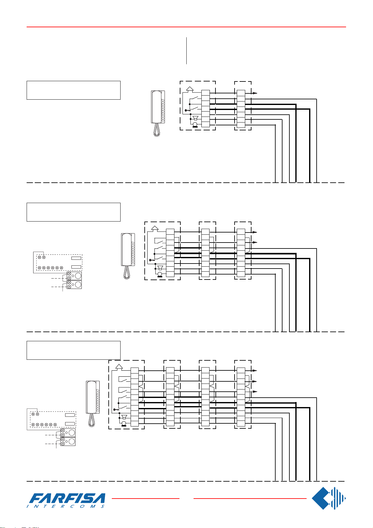
WORKING DIAGRAMS FOR INTERCOMMUNICATING SYSTEMS WITH A DOOR STATION AND INDIVIDUAL CALL.
ANWENDUNGSSCHALTPLÄNE FÜR MEHRFAMlLIENHAUS
GEGENSPRECHANLAGEN MIT TÜRSTATION.
Combine with the system Si 210/5.
2 intercommunicating intercoms
2 Gegensprechhaustelefone
3 intercommunicating intercoms
3 Gegensprechhaustelefone
9 7
2315P16
P2
P3
Connect one of the two terminals of the single button unit
to terminal 7.
Eine Anschlußklemme der Zusatztasten muß mit der
Klemme 7 verbunden werden.
Kombinierbar mit dem Schaltplan Si 210/5.
1
7
5
3
2
1
6
P1
CT2
6
2
P2
P1
1
7
5
3
2
1
CT3
+SP
P2
6
P1
7
5
3
2
1
CT2
+SP
P1
CT1
P1
P2
CT1
+SP
x2
6
7
5
3
2
1
xn
x2
6
7
5
3
2
1
4 intercommunicating intercoms
4 Gegensprechhaustelefone
6
3
P3
2
P2
P1
1
9 7
2315P16
P2
P3
Connect one of the two terminals of the single button unit
to terminal 7.
Eine Anschlußklemme der Zusatztasten muß mit der Klemme 7 verbunden werden.
7
5
3
2
1
CT4
+SP
P3
6
P2
P1
7
5
3
2
1
CT3
+SP
40
8 GbD-02
P2
P3
6
P1
7
5
3
2
1
CT2
+SP
P1
P3
P2
6
7
5
3
2
1
CT1
+SP
xn
x3
x2
Page 43
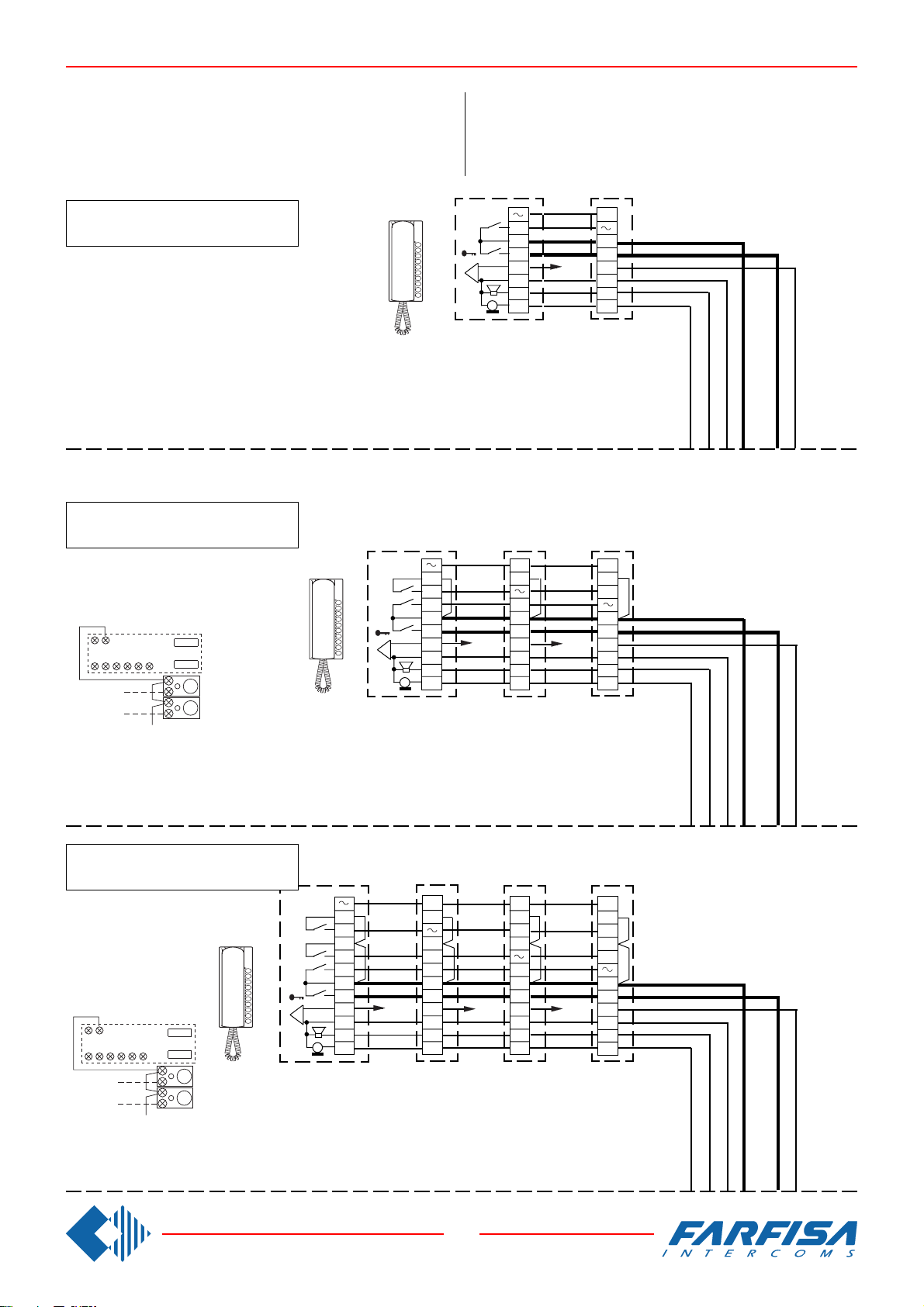
WORKING DIAGRAMS FOR INTERCOMMUNICATING SYSTEMS WITH A DOOR STATION AND INDIVIDUAL CALL AND
ELECTRONIC BELL FOR INTERNAL CALLS.
ANWENDUNGSSCHALTPLÄNE FÜR MEHRFAMlLIENHAUS
GEGENSPRECHANLAGEN MIT TÜRSTATION UND ELEKTRONISCHEM KLANGRUF FÜR INTERNRUFE.
Combine with the systems Si 220/5; Si 250/5.
2 intercommunicating intercoms
2 Gegensprechhaustelefone
3 intercommunicating intercoms
3 Gegensprechhaustelefone
9 7
2315P16
P2
P3
Connect one of the two terminals of the single button unit
to terminal 7.
Eine Anschlußklemme der Zusatztasten muß mit der
Klemme 7 verbunden werden.
SR 40
2
1
P2
P1
7
5
6
3
2
1
CT3
+SP
+RS
Kombinierbar mit den Schaltplänen Si 220/5 und Si 250/5.
SR 40
1
xn
P1
7
5
6
3
2
1
CT2
+RS
P2
P1
7
5
6
3
2
1
CT2
+SP
+RS
P1
7
5
x2
6
3
2
1
CT1
+RS
P1
P2
7
5
x2
6
3
2
1
CT1
+SP
+RS
4 intercommunicating intercoms
4 Gegensprechhaustelefone
SR 40
3
P3
2
P2
P1
1
7
5
6
3
9 7
2315P16
P2
P3
Connect one of the two terminals of the single button unit to
terminal 7.
Eine Anschlußklemme der Zusatztasten muß mit der Klemme 7 verbunden werden.
2
1
CT4+SP
+RS
P3
P2
P1
7
5
xn
6
3
2
1
CT3
+SP
+RS
P2
P3
P1
7
5
x3
6
3
2
1
CT2
+SP
+RS
P1
P3
P2
7
5
x2
6
3
2
1
CT1
+SP
+RS
41
8 GbD-02
Page 44
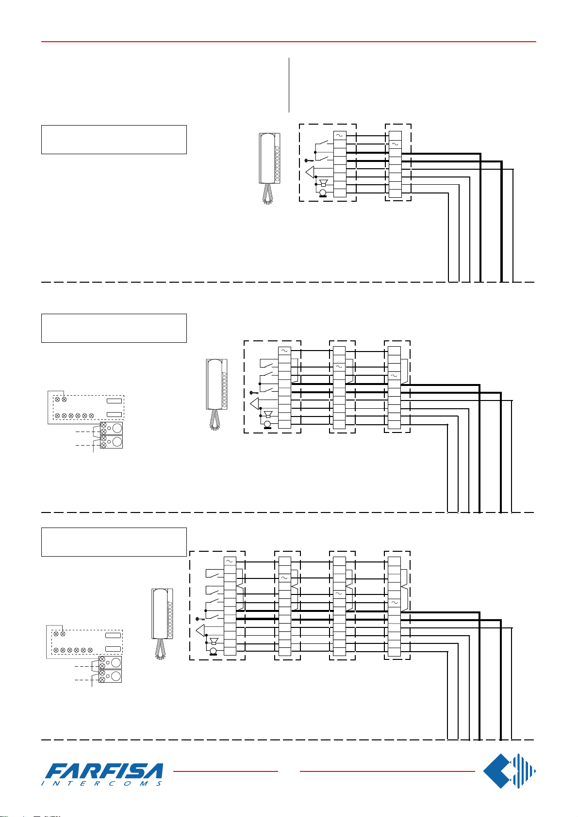
WORKING DIAGRAMS FOR INTERCOMMUNICATING SYSTEMS WITH A DOOR STATION AND COMMON CALL AND
ELECTRONIC BELL FOR INTERNAL CALLS.
ANWENDUNGSSCHALTPLÄNE FÜR EINFAMlLIENHAUS
GEGENSPRECHANLAGEN MIT TÜRSTATION UND ELEKTRONISCHEM KLANGRUF FÜR INTERNRUFE.
Combine with the systems Si 230/5.
2 intercommunicating intercoms
2 Gegensprechhaustelefone
3 intercommunicating intercoms
3 Gegensprechhaustelefone
9 7
2315P16
P2
P3
Connect one of the two terminals of the single button unit
to terminal 7.
Eine Anschlußklemme der Zusatztasten muß mit der
Klemme 7 verbunden werden.
SR 40
2
1
Kombinierbar mit dem Schaltplan Si 230/5.
P2
P1
7
5
6
3
2
1
CT3
+SP
+RS
SR 40
1
P1
7
5
6
3
2
1
CT2
+RS
P2
P1
7
5
6
3
2
1
CT2
+SP
+RS
P1
7
5
6
3
2
1
CT1
+RS
P1
P2
7
5
6
3
2
1
CT1
+SP
+RS
4 intercommunicating intercoms
4 Gegensprechhaustelefone
SR 40
3
P3
2
P2
1
P1
7
5
6
9 7
2315P16
P2
P3
CT4+SP+RS
Connect one of the two terminals of the single button unit
to terminal 7.
Eine Anschlußklemme der Zusatztasten muß mit der Klemme 7 verbunden werden.
3
2
1
P3
P2
P1
7
5
6
3
2
1
CT3
+SP
+RS
42
8 GbD-02
P2
P3
P1
7
5
6
3
2
1
CT2
+SP
+RS
P1
P3
P2
7
5
6
3
2
1
CT1
+SP
+RS
Page 45
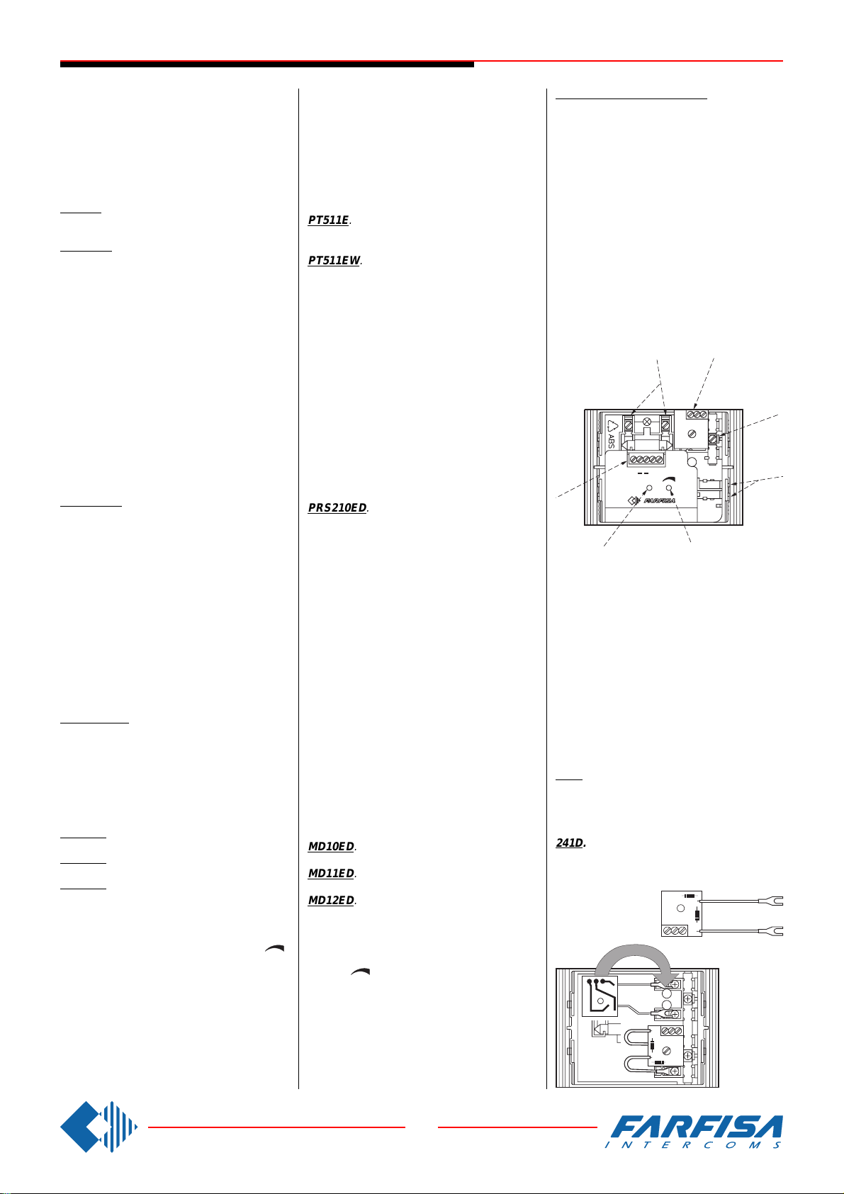
1+1 INTERCOM SYSTEMS /
P E P
A1S
PEP
ANTILOCALE
4.75.C091.01
PEPP E P
SPRECHANLAGEN 1+n
The products in this line can form an intercom
system with 1 cable shared by all the intercoms
and 1 for each individual intercom.
It is possible to receive a call from the door
station to talk and to activate the lock release
from any intercom.
INTERCOMS
PT511E. Two colour intercom. Complete with
a push-button, spiral cord, electronic microphone.
PT511EW. Colour: white.
Terminals
1 Audio line, bell and door release control
3 Ground
Application of the private conversation module (art.SM50)
To have complete audio privacy between users it is necessary to add to each intercom the
private conversation module art.SM50. The
intercom can communicate with the outside
(for an unlimited period) only after having received the call. The intercom becomes
disactived when there is a call from another
intercom or the door release push-button is
pressed.
TRANSFORMER WITH ELECTRONIC BELL
PRS 210ED.
Technical data
Input voltage: 127V or 230VAC
Power: 15VA
Bell frequency: 450 Hz modulated
4 module A DIN housing
Output terminals
- Ground
A Power supply 13VAC for:
- continuous load 0.6A (amplified door stations, name plate lamps-max.1 24V-3W)
- intermittent load 1A (electric door lock)
C- Negative electronic bell output 10Vpp-0.2A
PUSH-BUTTON PANELS
Mody series.
To make an 1+1 intercom installation it is
possible to use all button modules, the back
boxes, the rain shelters and hood covers described from page 6 to 9. Only the modules
MD10, MD11 and MD12 are different because
complet with door speaker (amplifier) and diode module.
MD10ED. Amplified module without call buttons.
MD11ED. Amplified module with one call button.
MD12ED. Amplified module with two call buttons.
Volume adjustment
To increase the volume from the amplifier in
the transmission mode, turn the trimmer “ ”
in a clockwise direction.
Antilocale adjustment
In case of "feedback" (Larsen effect) in the
external unit it is necessary to operate as
follow:
- Make the call from the door station and lift the
handset of an intercom.
- Adjust the trimmer “antilocale” until the whistling stops (Larsen effect).
Diese Artikelserie erlaubt die Herstellung von
Türsprechanlage mit einer gemeinsamen Ader
für alle Haustelefone und eine für jedes einzelne Sprechgerät. Jedes Haustelefon kann einen Anruf von der Türstation erhalten, mit
dieser ein Gespräch führen und am Ende die
Türöffnung betätigen.
HAUSTELEFONE PT511E. Haustelefon Farbe schwarz/grau für
den Einsatz mit 1+n Sprechanlagen. Mit Taste,
Spiralkabel und elektronischem Mikrofon.
PT511EW. Farbe weiß.
Anschlußklemmen
1 Sprechweg, Ruf und Türöffnersteuerung
3 Masse
Einbau eines Mithörsperrmoduls Art. SM50.
Um einen Mithörschutz zwischen den Teilnehmern zu gewährleisten, muß in jedem Haustelefon ein Mithörsperrmodul SM50 einbauen.
Das Haustelefon kann somit mit der Türstationzeitlich unbegrenzt sprechen, aber nur, nachdem es einen Anruf erhalten hat. Die Sprechverbindung des Haustelefons wird nach dem
Anruf zu einem anderen Haustelefon oder nach
dem Betätigen der Türöffnertaste gesperrt.
TRANSFORMATOR MIT ELEKTRONISCHEM TONRUF
PRS210ED.
Technische Daten
Netzspannung: 127V oder 230Vac
Leistung: 15VA
Tonruf: 450 Hz Alphaton
Gehäuse: 4 DIN A Module
Anschlußklemmen
- Masse
A
13V Wechselstromversorgung für:
-Türfreisprecheinrichtung, Namensschilderbeleuchtung (max. 1 zu 24V-3W) (Dauerbetrieb 0,6A)
- elektr.Türöffner (zeitbegrenzter Betrieb 1A)
C-
Ausgang negative Tonruf 10Vss/ 0,2A
TÜRSTATIONEN
Serie Mody
Für die Herstellung von 1+n Sprechanlagen
können alle Module wie auf den Seiten 6 bis 9
beschrieben eingesetzt werden. Nur die Module MD10, MD11 und MD12 unterscheiden
sich da für die 1+n Sprechanlagen diese komplett mit Türfreisprecheinrichtung und Diodenmodul geliefert werden.
MD10ED. Türsprechmodul komplett mit Tür-
freisprecheinrichtung ohne Ruftasten.
MD11ED. Türsprechmodul komplett mit Tür-
freisprecheinrichtung mit einer Ruftaste.
MD12ED. Türsprechmodul komplett mit Tür-
freisprecheinrichtung mit zwei Ruftasten.
Einstellung der Lautstärke
Um die Lautstärke auf dem Empfangskanal
des Verstärkers zu erhöhen drehen Sie den
Regler
“ ”
in Uhrzeitrichtung.
Einstellung des Rückkopplungseffektes
Um einen möglichen Pfeifton zu unterdrücken
folgen Sie diese Prozedur:
- einen Anruf von der Türstation einleiten und
Handapparat am Haustelefonabheben. Versichern Sie sich dabei das dieser mit dem Lautsprecher und Mikrofon nicht direkt gegen eine
harte Fläche (Wand, Tisch) gerichtet ist.
- agieren Sie auf den Regler ANTILOCALE, bis
der Pfeifton verschwindet.
43
8 GbD-02
MD10ED, MD11ED, MD12ED
1 Lamp terminals
2 Button terminal board
3 Call buttons common (terminal C)
4 Stair light button terminals
5 External volume adjustment
6 Feedback adjustment
7 Terminal board for audio/powering/electric
lock
Terminals
A Supply 13VAC-70mA
-
Ground
1 Reception-transmission; electric lock
release; call
S Electric lock
E Reception-transmission; electric lock
release
P Call button
7
6
1
2
3
4
5
1 Anschlußklemmen Beleuchtung
2 Anschlußklemmen Ruftasten
3 Anschlußklemme Rufspannung
4 Anschlußklemmen Zusatztaste
5 Lautstärkeneinstellung für Lautsprecher
6 Regelung der Rückkopplung
7 Anschlußklemmen Sprechweg, Stromversor-
gung, elektrischer Türöffner
A 13 Vac Stromversorgung - 70mA
- Masse
1 Sprechweg, Türöffnungssteuerung, Ruf
S Steuerspannung für Türöffner (13Vac)
E Sprechweg, Türöffnungssteuerung.
P Ruftaste
241D. Diode module for two users.
It is used inside the modules MD21, MD22,
MD23, MD24, MD222, MD224, MD226 and
MD228.
241D. Diodenmodul für 2 Teilnehmer.
Wird in den Ruftastenmodulen MD21, MD22,
MD23, MD24, MD222, MD224, MD226 und
MD228 eingebaut.
PEP
Page 46
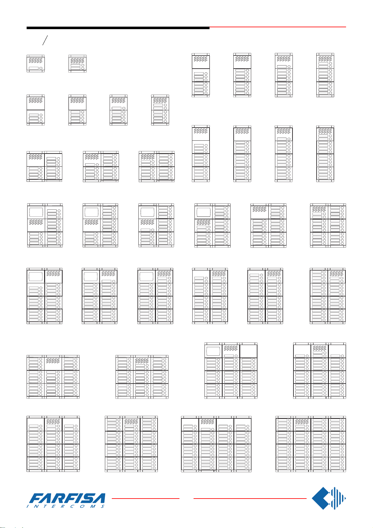
1+1 INTERCOM SYSTEMS /
SPRECHANLAGEN 1+n
Series
Serie
1 call button
1 Taste
- 1 row push-buttons
3 call buttons
3 Tasten
Mody
2 call buttons
2 Tasten
4 call buttons
4 Tasten
Einzeltasten
11 call buttons
11 Tasten
21 21
13 call buttons
13 Tasten
Examples of Mody push-button panel installations.
Beispiele für die Zusammensetzung von MODY Türstationen bei Sprechanlagen.
5 call buttons
5 Tasten
6 call buttons
6 Tasten
14 call buttons
14 Tasten
21
7 call buttons
7 Tasten
11 call buttons
11 Tasten
21
8 call buttons
8 Tasten
12 call buttons
12 Tasten
9 call buttons
9 Tasten
13 call buttons
13 Tasten
10 call buttons
10 Tasten
14 call buttons
14 Tasten
15 call buttons
15 Tasten
21 2121
23 call buttons
23 Tasten
32 call buttons
32 Tasten
25 call buttons
25 Tasten
16 call buttons
16 Tasten
17 call buttons
17 Tasten
26 call buttons
26 Tasten
34 call buttons
34 Tasten
18 call buttons
18 Tasten
28 call buttons
28 Tasten
21
37 call buttons
37 Tasten
20 call buttons
20 Tasten
29 call buttons
29 Tasten
22 call buttons
22 Tasten
30 call buttons
30 Tasten
40 call buttons
40 Tasten
42 call buttons
42 Tasten
46 call buttons
46 Tasten
55 call buttons
55 Tasten
44
8 GbD-02
62 call buttons
62 Tasten
Page 47
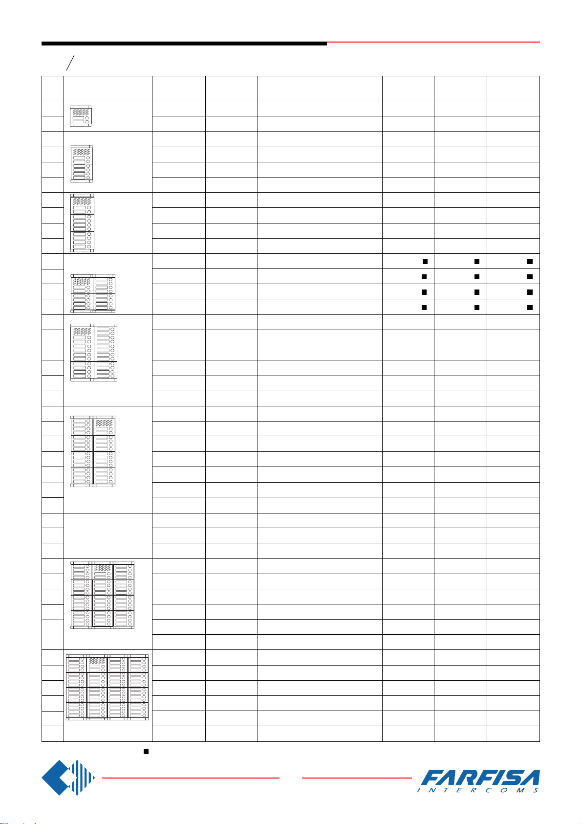
1+1 INTERCOM SYSTEMS /
SPRECHANLAGEN 1+n
Series
Serie
Tasten
Mody
Compositions and dimensions
N°
calls
Ansicht und Maße
1
2
3
4
5
6
7
8
9
10
11
(L x H x P)
12
13
14
15
16
17
18
20
22
248x304,5x19
(L x H x P)
23
24
25
27
28
29
30
248x395x19
(L x H x P)
31
32
372x304,5x19
(L x H x P)
34
35
37
40
42
43
46
372x395x19
(L x H x P)
48
50
53
55
58
62
496x395x19
(L x H x P)
124x121,5x19
(L x H x P)
(L x H x B)
124x213x19
(L x H x P)
(L x H x B)
124x304,5x19
(L x H x P)
(L x H x B)
248x213x19
(L x H x B)
(L x H x B)
(L x H x B)
(L x H x B)
(L x H x B)
(L x H x B)
Composition board of Mody push-button panels in 1+1 intercom installations.
Amplified module
Türfreisprechein-
richtung
1 MD11ED
1 MD12ED
1 MD10ED
1 MD10ED
1 MD11ED
1 MD12ED
1 MD10ED
1 MD10ED
1 MD11ED
1 MD12ED
1 MD10ED
1 MD10ED
1 MD11ED
1 MD12ED
1 MD10ED
1 MD10ED
1 MD11ED
1 MD12ED
1 MD12ED
1 MD12ED
1 MD10ED
1 MD10ED
1 MD11ED
1 MD12ED
1 MD12ED
1 MD12ED
1 MD12ED
1 MD12ED
1 MD10ED
1 MD12ED
1 MD10ED
1 MD11ED
1 MD12ED
1 MD12ED
1 MD12ED
1 MD12ED
1 MD10ED
1 MD10ED
1 MD11ED
1 MD11ED
1 MD11ED
1 MD12ED
or/
oder
MD74 or/
Tabelle zur Konfiguration von MODY Türstationen bei 1+n Sprechanlagen
Module 2 diodes
Diodenmodul für
2 Teilnehmer
-
2 241D
2 241D
2 241D
2 241D
4 241D
4 241D
4 241D
4 241D
6 241D
6 241D
6 241D
6 241D
8 241D
8 241D
8 241D
8 241D
9 241D
10 241D
12 241D
12 241D
12 241D
13 241D
13 241D
14 241D
14 241D
15 241D
16 241D
16 241D
18 241D
18 241D
20 241D
20 241D
21 241D
22 241D
24 241D
26 241D
26 241D
27 241D
30 241D
30 241D
oder
MD804 or/
Button, info an/or blank module
Ruftastenmodule, Informationsmodul
1 MD23
1 MD24
1 MD24
1 MD24
1 MD24
2 MD24
2 MD24
2 MD24
2 MD24
3 MD24
3 MD24
3 MD24
3 MD24
4 MD24
4 MD24
4 MD24
4 MD24
5 MD24
5 MD24
6 MD24
6 MD24
6 MD24
6 MD24
6 MD24
7 MD24
7 MD24
8 MD24
8 MD24
8 MD24
9 MD24
9 MD24
9 MD24
10 MD24
11 MD24
12 MD24
12 MD24
12 MD24
12 MD24
12 MD24
15 MD24
oder
-
-
MD904
und Leermodul
-
-
-
-
-
-
1 MD23
-
-
-
1 MD23
-
-
-
1 MD23
-
-
-
1 MD22
-
1 MD23
-
1 MD21
1 MD22
1 MD23
1 MD21
-
1 MD23
2 MD21
2 MD22
1 MD21
-
2 MD21
2 MD22
3 MD22
3 MD23
-
* or MD50 /
-
-
-
-
-
-
-
-
-
-
-
-
-
1 MD20 *
1 MD20 *
1 MD20 *
1 MD20 *
-
1 MD20 *
1 MD20 *
1 MD20 *
-
-
-
-
-
-
2 MD20 *
2 MD20 *
-
-
-
3 MD20 *
1 MD20 *
1 MD20 *
-
-
-
Back box
Unterputz-
gehäuse
1 MD71
1 MD71
1 MD72
1 MD72
1 MD72
1 MD72
1 MD73
1 MD73
1 MD73
1 MD73
2 MD72
2 MD72
2 MD72
2 MD72
2 MD73
2 MD73
2 MD73
2 MD73
2 MD73
2 MD73
2 MD74
2 MD74
2 MD74
2 MD74
2 MD74
2 MD74
2 MD74
3 MD73
3 MD73
3 MD73
3 MD74
3 MD74
3 MD74
3 MD74
3 MD74
3 MD74
4 MD74
4 MD74
4 MD74
4 MD74
4 MD74
4 MD74
oder MD50
Hood covers
Wasserschutz
1 MD81
1 MD81
1 MD82
1 MD82
1 MD82
1 MD82
1 MD83
1 MD83
1 MD83
1 MD83
1 MD84
1 MD84
1 MD84
1 MD84
1 MD86
1 MD86
1 MD86
1 MD86
1 MD86
1 MD86
1 MD808
1 MD808
1 MD808
1 MD808
1 MD808
1 MD808
1 MD808
1 MD89
1 MD89
1 MD89
1 MD812
1 MD812
1 MD812
1 MD812
1 MD812
1 MD812
-
-
-
-
-
-
Rain shelter
Aufputzgehäuse
1 MD91
1 MD91
1 MD92
1 MD92
1 MD92
1 MD92
1 MD93
1 MD93
1 MD93
1 MD93
1 MD94
1 MD94
1 MD94
1 MD94
1 MD96
1 MD96
1 MD96
1 MD96
1 MD96
1 MD96
1 MD904
1 MD904
1 MD904
1 MD904
1 MD904
1 MD904
1 MD904
1 MD99
1 MD99
1 MD99
1 MD912
1 MD912
1 MD912
1 MD912
1 MD912
1 MD912
-
-
-
-
-
-
.
- 1 row push-buttons
Einzeltasten
45
8 GbD-02
Page 48
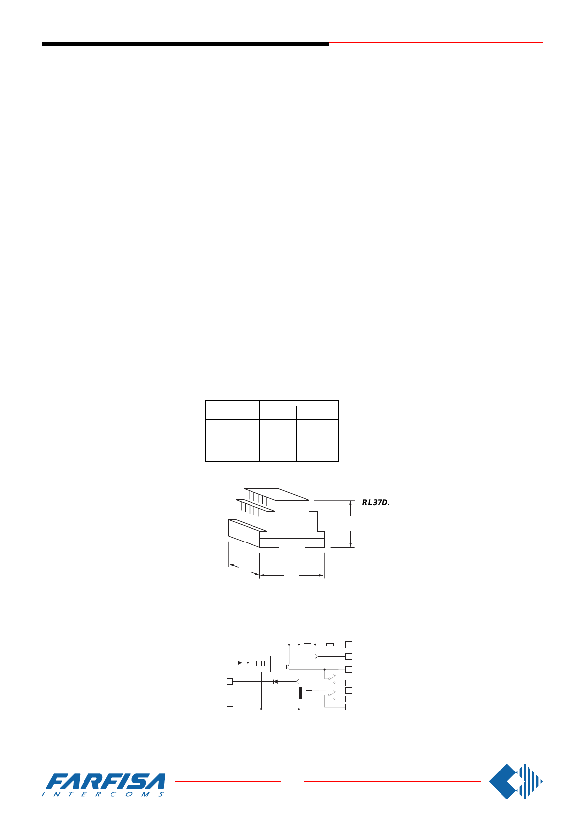
1+1 INTERCOM SYSTEMS /
SPRECHANLAGEN 1+n
INSTALLATION RULES
- Cable channels of intercom installations must be kept separate
from lighting or industrial systems as required by CEI Standards.
Installations must be realised according to the provisions of the
law.
- A protective switched circuit-breaker must be provided before the
power supply. Use a single general switch in case of multiple power
supplies (also for multiple entrances).
- Before connecting the power supply make sure that the rating
complies with the electrical mains.
Wires
1) Wires must be dimensioned according to the distance between the
devices and according to their consumption.
2) Do not use multiple wires in parallel to reach the requested cross-
section (for example multipair telephone cables). Use a single wire
with suitable cross-section. In case of multicore cables use cables
with low parasite parameters (low capacity per metre, low inductance over Ohm).
3) If the installation includes additional power supplies, place them
near the devices to be powered.
Background noise
To avoid background noise over the voice line, it is recommended:
1) not to use the same cable channel for intercom cables and wires
with AC loads;
2) to avoid using the same multicore cable for the transmission of
voice signals and for AC power supplies (lamps, amplified external
stations, electrical locks). Always use separate wires for AC power
supplies;
3) for name plate lighting use a 12V additional transformer (PRS210
type) with suitable capacity (consumption
is 75mA for each lamp), keeping the 2
power supply wires separate from the
voice wires.
CABLE CROSS SECTION
DURCHMESSER VERBINDUNGENSKABEL
m.
50
100
200
mm²
0.75
1
1.5
INSTALLATIONSVORSCHRIFTEN
- Die Leiter jeder Art von Sprechanlagen müssen in separaten Rohren,
getrennt von der Beleuchtungs- oder Industrieanlage geführt werden,
wie in den CEI-Normen vorgeschrieben ist. Die gesamte Anlage ist
gemäß den Bestimmungen der einschlägigen Gesetze auszuführen.
- Vor dem Netzgerät muss ein geeigneter Streckenausschalter und Schutzschalter installiert werden. Sind mehrere (auch auf mehrere Stockwerke
unterteilte) Netzgeräte vorhanden, ist ein einziger Hauptschalter vorzusehen.
- Vor Anschluss des Netzgeräts ist sicherzustellen, dass die technischen
Daten auf dem Typenschild mit denen des Stromnetzes übereinstimmen.
Leiter
1)Die Leiter sind entsprechend dem Abstand zwischen den verschiedenen
Geräten und gemäß deren Stromaufnahme auszulegen.
2)Zur Erzielung des geforderten Querschnitts dürfen nicht mehrere Leiter
(z.B. vielpaarige Telefonleiter) parallel verlegt werden, sondern es darf
nur ein Leiter angemessenen Querschnitts verwendet werden. Bei
Verwendung von Multipolkabeln sind Kabel mit niedrigen Störwerten
einzusetzen (geringe Kapazität pro Meter, geringe Ohm-Induktivität).
3)Wenn in der Anlage Zusatz-Netzgeräte vorgesehen sind, sind diese in
der Nähe der von ihnen versorgten Geräte anzubringen.
Hintergrundgeräusch
Zur Vermeidung von Hintergrundgeräuschen in der Sprechleitung sollten
folgende Empfehlungen beachtet werden:
1)Leiter der Sprechgeräte nicht in denselben Rohren verlegen, in denen
die Leiter von wechselstromversorgten Geräten geführt werden;
2)Multipolkabel nicht zur Übertragung von Schallsignalen und gleichzeitig
auch zur Versorgung von wechselstromversorgten Geräten (Lampen,
mm
1
1,2
1,4
Türstationen mit Verstärkern, Elektrotürschlösser) verwenden. Für die Versorgung
von Wechselstromgeräten sind stets getrennte
Leiter zu verwenden;
3)Für die Versorgung der Namensschilderbeleuchtung wird ein Zusatztransformator (des
Typs PRS210) zu 12V und angemessener Leistung (jede Lampe nimmt 75mA auf) mit je 2, von
den Schallleitern getrennten, Versorgungsleitern
empfohlen.
Supplementary call module
RL37D. When installed in 1+1 intercom with elec-
tronic call, it provides a supplementary input for
external calls or provide a second ringer for floor
calls.
Technical data
Power supply: 13Vac
Stand-by current: 40mA
Max. switching current: 1A (24V)
Housing: DIN 4 A modules
Terminals
A 13Vac alternate voltage input
- ground
H timed positive continuous voltage input 21Vdc
IV supplementary power supply enabling
C common contact of relay
NA normally open contact of relay
NC normally closed contact of relay
1P electronic call input
1M electronic call output enabled from terminal 1P
CP electronic call output
Note: Remove the cover and move jumper J2 to
change the electronic ringer of CP and 1M outputs.
Position 1-2: modulated note
Position 2-3: continuous note
Modul zum Neustarten der Rufe
RL37D. Wird in 1+1 Sprechanlagen mit elektroni-
schem Klangruf verwendet und ermöglicht es, Außenrufe zu wiederholen oder einen elektronischen Eta-
65
gen-Klangruf zu erzeugen.
Technische Daten
Stromversorgung: 13V Ws
70
A
1P
89
Aufnahme in Ruhestellung: 40mA
Max. Umschaltstrom: 1A (24V)
Gehäuse: DIN 4 Module A
Klemmen
A
Wechselstromeingang 13V Ws
- Masse
H Gleichstromeingang, zeitgeschaltet 21V Gs
IV Aktivierung des Zusatznetzgeräts
IV
C gemeinsame Klemme f. Relaisweiche
NA N/O kontakt Relais
H
NC N/C kontakt Relais
CP
1P Eingang Elektronikruf
1M
1M Ausgang Elektronikruf, aktiviert von Klemme 1P
NC
CP Ausgang Elektronikruf
NA
Anmerkung: Zur Veränderung der Klangfarbe des
C
Elektronikläutwerkes der Ausgänge CP und 1M ist
der Deckel zu entfernen und die Brücke J2 zu
verschieben.
Position 1-2: modulierte Note
Position 2-3: Dauerton
46
8 GbD-02
Page 49
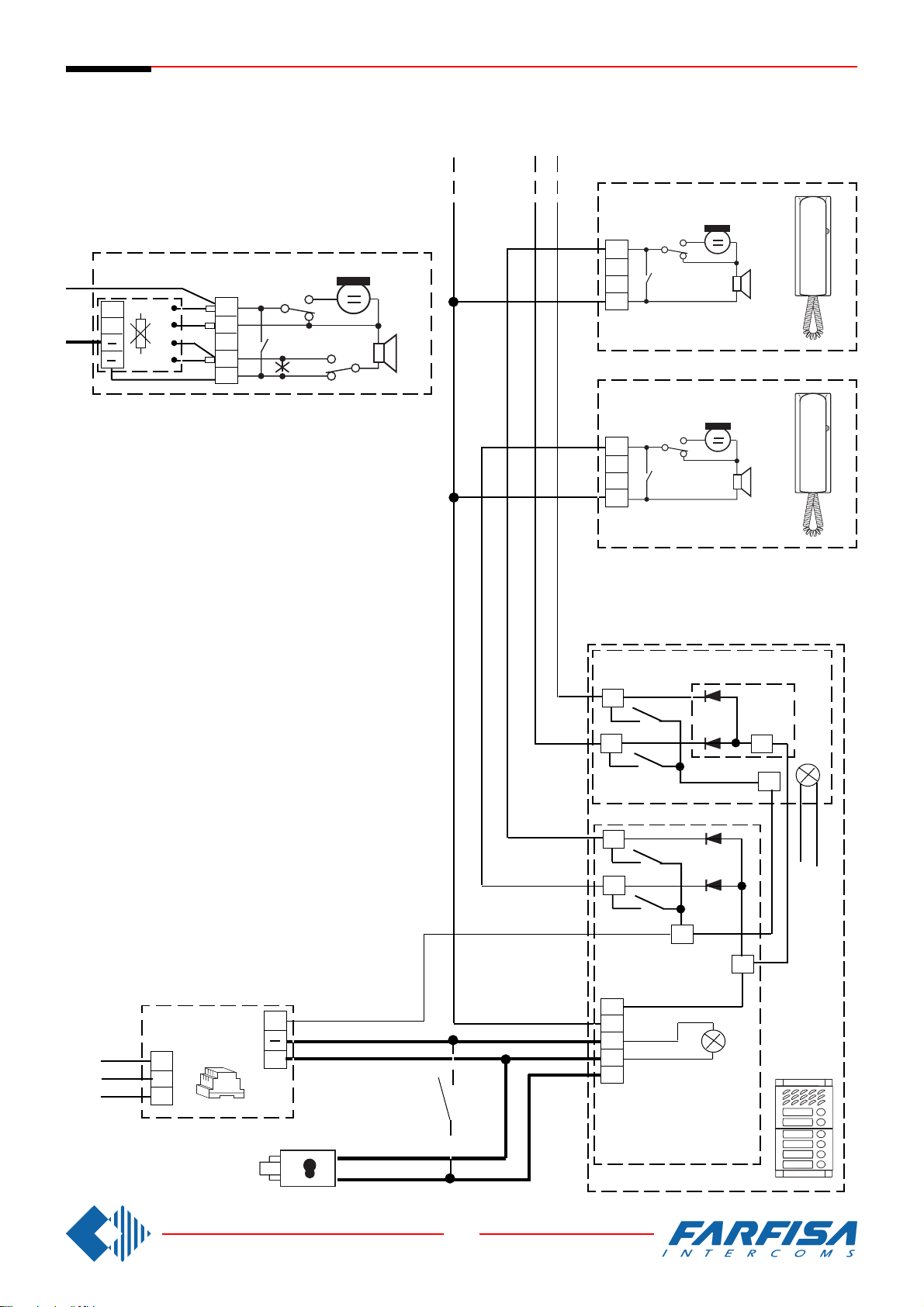
Si 21MR/1
1+1 intercom systems
INTERCOMS CONNECTED TO A DOOR STATION SERIES MODY (1+1 system).
MEHRFAMILIENHÄUS SPRECHANLAGE 1+n MIT ElNER TÜRSTATION DER SERIE MODY.
Connection of privacy module SM50 in PT511E intercom.
Sprechanlagen 1+n
CT2
Einbau eines Mithörsperrmoduls SM50 in einem Haustelefone PT511E.
1
CT
C
B
R1
PT511E + SM50
1
6
2
3
1
6
3
7
3
PT511E
W1
CT1
In each intercom it is necessary:
- to cut the jumper (W1) that links the terminals 3 and 7;
- to activate the connection between terminal 7 of the
intercom and the - (minus) of the private conversation
module.
ln jedem Haustelefon muß man:
- die Drahtbrücke (W1) unterbrechen, um die Anschlußklemmen 3 und 7 zu trennen;
- die Verbindung zwischen Anschlußklemme 7 des Haustelefons und der Anschlußklemme – (minus) des Mithörsperrmoduls einsetzen.
1
3
PT511E
230V
127V
0
PRS 210ED
C-
MD21 ÷ MD228
P
P
P
P
C
1
241D
E
C
E
-
-
A
PA
(optional)
A
S
MD10ED
MD11ED
MD12ED
SE
47
8 GbD-02
Page 50
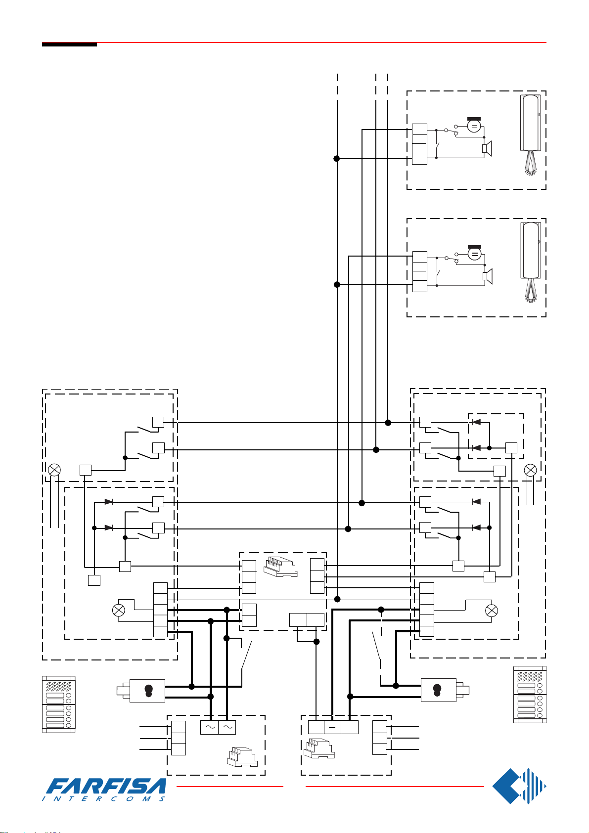
Si 22MR/1
1+1 intercom systems
INTERCOMS CONNECTED TO TWO DOOR STATIONS SERIES
MODY WITH AUTOMATIC SWITCHING (1+1 system).
MEHRFAMILIENHAUS SPRECHANLAGE 1+n MIT ZWEI UMSCHALTBAREN TÜRSTATIONEN DER SERIE MODY.
Sprechanlagen 1+n
CT2
1
3
PT511E
CT1
1
3
PT511E
MD21 ÷ MD228
C
C
E
MD10ED-11ED-12ED
SE
" b "
" a "
MD21 ÷ MD228
P
P
P
P
6
1
7a
1473
3
7
7b
-
-
A
S
2
4
1
5
P
P
P
P
C
1
241D
E
C
E
-
-
A
S
MD10ED-11ED-12ED
(optional)
PA
(optional)
PA
SE
230V
127V
0
PRS 210
48
8 GbD-02
C-
PRS 210ED
A
230V
127V
0
 Loading...