


 Loading...
GE Fanuc Automation
Programmable Control Products
VersaMax™ System
Genius® Network Interface Unit
User's Manual
GFK-1535A |
November 2000 |

GFL-002
Warnings, Cautions, and Notes as Used in this Publication
Warning
Warning notices are used in this publication to emphasize that hazardous voltages, currents, temperatures, or other conditions that could cause personal injury exist in this equipment or may be associated with its use.
In situations where inattention could cause either personal injury or damage to equipment, a Warning notice is used.
Caution
Caution notices are used where equipment might be damaged if care is not taken.
Note
Notes merely call attention to information that is especially significant to understanding and operating the equipment.
This document is based on information available at the time of its publication. While efforts have been made to be accurate, the information contained herein does not purport to cover all details or variations in hardware or software, nor to provide for every possible contingency in connection with installation, operation, or maintenance. Features may be described herein which are not present in all hardware and software systems. GE Fanuc Automation assumes no obligation of notice to holders of this document with respect to changes subsequently made.
GE Fanuc Automation makes no representation or warranty, expressed, implied, or statutory with respect to, and assumes no responsibility for the accuracy, completeness, sufficiency, or usefulness of the information contained herein. No warranties of merchantability or fitness for purpose shall apply.
The following are trademarks of GE Fanuc Automation North America, Inc.
Alarm Master |
Genius |
PowerTRAC |
Series Six |
CIMPLICITY |
Helpmate |
ProLoop |
Series Three |
CIMPLICITY 90–ADS |
Logicmaster |
PROMACRO |
VersaMax |
CIMSTAR |
Modelmaster |
Series Five |
VersaPro |
Field Control |
Motion Mate |
Series 90 |
VuMaster |
GEnet |
PowerMotion |
Series One |
Workmaster |
©Copyright 2000 GE Fanuc Automation North America, Inc.
All Rights Reserved
|
|
Contents |
Chapter 1 |
Introduction............................................................................................ |
1-1 |
|
Related Manuals.................................................................................................. |
1-2 |
|
The VersaMax Family of Products ................................................................... |
1-3 |
|
The VersaMax Genius I/O Station ....................................................................... |
1-4 |
|
The Genius NIU.................................................................................................. |
1-5 |
|
Genius NIU Specifications .................................................................................. |
1-6 |
|
Power Supplies ................................................................................................... |
1-7 |
|
I/O Modules........................................................................................................ |
1-8 |
|
Carriers............................................................................................................. |
1-11 |
|
Expansion Modules ........................................................................................... |
1-13 |
|
VersaMax General Product Specifications ......................................................... |
1-15 |
Chapter 2 |
Installation.............................................................................................. |
2-1 |
|
Module Clearance ............................................................................................... |
2-2 |
|
Thermal Considerations....................................................................................... |
2-3 |
|
Mounting Instructions ......................................................................................... |
2-4 |
|
Panel-Mounting .................................................................................................. |
2-5 |
|
Installing an Expansion Transmitter Module ........................................................ |
2-6 |
|
Installing an Expansion Receiver Module ............................................................ |
2-7 |
|
Installing Power Supply Modules ...................................................................... |
2-10 |
|
Installing Additional Modules............................................................................ |
2-11 |
|
Setting the SBA and Baud Rate ......................................................................... |
2-12 |
|
Special Switch Settings on the NIU ................................................................... |
2-13 |
|
Selecting a Cable Type ...................................................................................... |
2-15 |
|
Bus Length........................................................................................................ |
2-17 |
|
Making Bus Connections................................................................................... |
2-18 |
|
Observing the LEDs .......................................................................................... |
2-20 |
|
CE Mark Installation Requirements ................................................................... |
2-21 |
Chapter 3 |
Operation................................................................................................ |
3-1 |
|
NIU Data Memories ............................................................................................ |
3-2 |
|
Scanning Inputs and Outputs in the I/O Station .................................................... |
3-3 |
|
Data Transfer Between the NIU and the Bus ........................................................ |
3-4 |
|
Genius Bus Scan Time ........................................................................................ |
3-7 |
Chapter 4 |
Configuring a Genius NIU and I/O Station ........................................... |
4-1 |
|
Using Autoconfiguration or Programmer Configuration ....................................... |
4-2 |
|
Configuring “Racks” and “Slots”......................................................................... |
4-3 |
|
Software Configuration of the Genius NIU and I/O Station .................................. |
4-5 |
GFK-1535A |
iii |

Contents
|
Autoconfiguration of the Genius NIU and I/O Station ........................................ |
4-10 |
|
How Autoconfiguration Handles Equipment Changes........................................ |
4-13 |
Chapter 5 |
Datagrams .............................................................................................. |
5-1 |
|
Datagram Types .................................................................................................. |
5-2 |
|
Read Map ........................................................................................................... |
5-3 |
|
Read Map Reply.................................................................................................. |
5-3 |
|
Report Fault Datagram Format ............................................................................ |
5-4 |
|
Configuration Data.............................................................................................. |
5-6 |
|
Set NIU Operating Mode................................................................................... |
5-20 |
Chapter 6 |
Redundancy............................................................................................ |
6-1 |
|
CPU/Bus Controller Redundancy......................................................................... |
6-2 |
|
Using the NIU in a Genius Bus Redundancy System ............................................ |
6-3 |
Appendix A |
Operation of the Genius Bus.................................................................. |
A-1 |
|
Electrical Interface .............................................................................................. |
A-2 |
|
Serial Bus Waveforms......................................................................................... |
A-3 |
|
Maximum Bus Length ......................................................................................... |
A-4 |
|
Serial Data Format .............................................................................................. |
A-6 |
|
Genius Transceiver Electrical Specification ......................................................... |
A-7 |
|
Bus Errors........................................................................................................... |
A-7 |
Appendix B |
Performance Data .................................................................................. |
B-1 |
iv |
VersaMax™ System Genius® Network Interface Unit User's Manual– November 2000 |
GFK-1535A |

Chapter Introduction
1
This manual explains how to install and use a VersaMax™ Genius® Network
Interface Unit module to interface VersaMax I/O modules to a Genius bus.
NIU installation procedures are described in Chapter 2.
NIU operation is described in chapter 3. This chapter explains how the NIU interacts with the modules in its station, how it stores data, and how it exchanges data with the system host.
Configuration is described in chapter 4.
The datagrams that can be sent to an NIU are described in chapter 5.
Genius Bus and CPU Redundancy options are explained in chapter 6.
Bus operation is detailed in appendix A.
Appendix B lists I/O module scan time performance data.
GFK-1535A |
1-1 |

1 |
Related Manuals
VersaMax Modules, Power Supplies, |
Describes the many VersaMax I/O and option |
and Carriers User’s Manual (catalog |
modules, power supplies, and carriers. This |
number GFK-1504) |
manual also provides detailed system |
|
installation instructions. |
|
|
Remote I/O Manager User’s Guide |
Gives step-by-step instructions for using the |
(catalog number GFK-1847). |
Remote I/O Manager configuration software. |
VersaMax Ethernet Network Interface Describes the installation and operation of the Unit User’s Manual (catalog number Ethernet Network Interface Unit module. GFK-1860)
VersaMax DeviceNet Communications |
Describes the installation and operation of the |
Modules User’s Manual (catalog |
DeviceNet Network Interface Unit module and |
number GFK-1533) |
the DeviceNet Network Slave Module. |
|
|
VersaMax Profibus Communications |
Describes the installation and operation of the |
Modules User’s Manual (catalog |
Profibus Network Interface Unit module and |
number GFK-1534) |
the Profibus Network Communications |
|
Module. |
|
|
VersaMax PLC User’s Manual (catalog |
Describes the installation and operation of the |
number GFK-1503) |
VersaMax CPU. |
Genius System and Communications Provides detailed reference information about Manual (catalog number GEK-90486-1). Genius communications and message
formats.
1-2 |
VersaMax™ System Genius® Network Interface Unit User's Manual – November 2000 |
GFK-1535A |

1 |
The VersaMax Family of Products
The VersaMax family of products provides universally-distributed I/O that spans PLC and PC-based architectures. Designed for industrial and commercial automation, VersaMax I/O provides a common, flexible I/O structure for local and remote control applications. The VersaMax PLC provides big-PLC power with a full range of I/O and option modules. VersaMax I/O Stations with Network Interface Modules make it possible to add the flexibility of VersaMax I/O to other types of networks. VersaMax meets UL, CUL, CE, Class1 Zone 2 and Class I Division 2 requirements.
As a scaleable automation solution, VersaMax I/O combines compactness and modularity for greater ease of use. The 70-mm depth and small footprint of VersaMax I/O enables easy, convenient mounting as well as space-saving benefits. Modules can accommodate up to 32 points of I/O each.
The compact, modular VersaMax products feature DIN-rail mounting with up to eight I/O and option modules per “rack” and up to 8 racks per VersaMax PLC or VersaMax I/O Station system. Expansion racks can be located up to 750 meters from the main VersaMax PLC or VersaMax I/O Station rack. Expansion racks can include any VersaMax I/O, option, or communications module.
VersaMax provides automatic addressing that can eliminate traditional configuration and the need for hand-held devices. Multiple field wiring termination options provide support for two, three, and four-wire devices.
For faster equipment repair and shorter Mean-Time-To-Repair, the hot insertion feature enables addition and replacement of I/O modules while a machine or process is running and without affecting field wiring.
GFK-1535A |
Chapter 1 Introduction |
1-3 |

1 |
The VersaMax Genius I/O Station
A VersaMax PLC consists of a group of VersaMax modules with a VersaMax CPU and attached power supply in the first position.
Genius NIU |
VersaMax Modules |
power supply
An I/O Station provides up to 64 analog channels and up to 1024 discrete points for 256 total bytes of I/O. The NIU operates as a device on a Genius bus, automatically exchanging I/O, diagnostic, and control data with a PLC or host computer.
VersaMax I/O in a Genius System
An I/O station can be used on the same bus as Genius I/O blocks, Field Control I/O stations, and Remote I/O drops.
Host Computer
Series 90-30 PLC with bus controller module
Series 90-30 PLC with communications module

 PCIM
PCIM
Genius Bus
NIU |
NIU |
Genius I/O Blocks |
Series 90-70 Remote I/O Drop |
NIU |
Field Control™ I/O Station
VersaMax™ I/O Stations
VersaMax I/O stations can be used in redundant bus and redundant CPU applications. The Genius NIU provides built-in bus-switching capability. See chapter 6 for more information about using the NIU in a redundancy system.
1-4 |
VersaMax™ System Genius® Network Interface Unit User's Manual – November 2000 |
GFK-1535A |

1 |
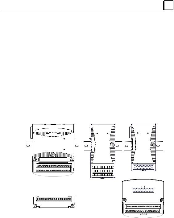
The Genius NIU
The VersaMax Genius Network Interface Unit (IC200GBI001) interfaces a VersaMax I/O Station to a Genius I/O bus. The system host can be any PLC or computer capable of controlling the Genius bus.
E |
|
|
|
|
|
GBI001 |
|
|
|
||
PWR |
|
|
|
||
|
OK |
|
|
|
|
FAULT |
|
|
|
||
I/O ENBL |
|
|
|
||
FORCE |
|
|
|
||
SBA ERR |
|
IC200GBI001 |
|||
BUS B |
|
Genius® NIU |
|||
|
|
|
|
THIS DEVICE COMPLIES WITH PART 15 OF |
|
|
|
|
|
THE FCC RULES. OPERATION IS SUBJECT |
|
|
|
|
|
TO THE FOLLOWING CONDITIONS: |
|
U |
0 |
1 |
|
1) THIS DEVICE MAY NOT CAUSE |
|
|
|
HARMFUL INTERFERENCE. |
|||
A |
|
2 |
SBA |
2) |
THIS DEVICE MUST ACCEPT ANY |
N |
|
3 |
X10 |
|
INTERFERENCE RECEIVED, INCLUDING |
|
|
INTERFERENCE THAT MAY CAUSE |
|||
|
|
|
|
|
|
|
0 |
|
|
|
UNDESIRED OPERATION. |
9 |
1 |
|
THIS DIGITAL APPARATUS DOES NOT |
||
8 |
|
2 |
SBA |
EXCEED THE CLASS A LIMITS FOR RADIO |
|
7 |
|
3 |
X1 |
NOISE EMISSIONS FROM DIGITAL APPARATUS |
|
|
SET OUT IN THE RADIO INTERFERENCE |
||||
6 |
5 |
4 |
|
||
|
REGULATIONS OF THE CANADIAN DEPART- |
||||
|
0 |
1 |
|
MENT OF COMMUNICATIONS. FOR USE IN |
|
|
|
2 |
BAUD |
A CONTROLLED ENVIRONMENT. REFER TO |
|
N |
|
3 |
RATE |
MANUALS FOR ENVIRONMENTAL |
|
|
CONDITIONS. |
||||
|
|
|
|
ENCAD D'UTILISATION EN ATMOSPHERE |
|
|
|
|
|
CONTROLEE. CONSULTER LA NOTICE |
|
|
|
|
|
TECHNIQUE. |
|
SERIAL A1 |
IND CONT EQ FOR HAZ LOC |
|
CLASS I DIV 2 GROUPS ABCD |
||
|
||
SERIAL A2 |
Ambient 60C |
|
SHIELD IN |
CLASS I ZONE 2 GROUP IIC |
|
Ex nA II 0C<To<60C |
||
SHIELD OUT |
||
Ex nV II |
||
|
Demko No. 98Y 125014 |
|
|
MADE IN USA |
|
SERIAL B1 |
|
|
SERIAL B2 |
|
|
SHIELD IN |
|
|
SHIELD OUT |
|
The Network Interface Unit installs on a 35mm x 7.5mm conductive DIN rail. A VersaMax power supply module mounts directly on the righthand side of the NIU. LEDs on the lefthand side indicate the presence of power and show the operating mode and status of the NIU. Three rotary dials beneath a clear protective door are used to configure the NIU’s address on the Genius bus and to set its communications baud rate. Removable connectors are used to install single or redundant bus cables. These connectors make it possible to disconnect a bus cable from the NIU without breaking the continuity of the bus, so other devices on the same bus can continue operating.
GFK-1535A |
Chapter 1 Introduction |
1-5 |

1 |
Genius NIU Specifications
Number of Modules |
8 per rack, 64 per NIU/station |
|
|
Network inputs per bus scan |
128 bytes |
|
|
Network outputs per bus scan |
128 bytes |
|
|
Discrete Input Memory |
1024 points |
|
|
Discrete Output Memory |
1024 points |
|
|
Analog Input Memory |
64 channels |
|
|
Analog Output Memory |
64 channels |
|
|
Power Consumption |
+5V@250mA, +3.3V@10mA |
|
|
Serial Bus Address |
0 to 31 |
|
|
Network data rate |
153.6 Kbaud extended, 153.6 Kbaud |
|
standard, 76.8 Kbaud, or 38.4 Kbaud. |
|
|
Genius NIU Compatibility
Network Interface Unit IC200GBI001 is compatible with:
TFor a Series 90™ -70 PLC
V CPU firmware, release 3.0 or later. V Bus controller release 5.4 or later.
VIf the IC641SWP701/704 programming and configuration software is used, it must be release 3.0 or later:
TFor a Series 90™ -30 PLC
V CPU firmware: any version. For expansion compatibility for CPUs 350, 352, 360, 363, and 364, version 10.0 or later is needed. Versions earlier than 10.0 of any Series 90-30 CPU will go to Stop/Faulted mode if an Add/Loss of Rack (expansion) fault is logged.
V Bus Controller: any version.
TFor a Series Six™ PLC:
V CPU: rev. 105 or later
V Programming Software: Release 4.02 or later
V Bus controllers: IC660CBB902 or 903, version 1.7 or later
1-6 |
VersaMax™ System Genius® Network Interface Unit User's Manual – November 2000 |
GFK-1535A |
1 |
Power Supplies
An AC or DC Power Supply module installs directly on the NIU. The Power Supply provides +5V and +3.3V power to the modules in the station. Additional power supplies can be installed on special booster carriers if needed for systems where the number of modules creates the need for a booster. No booster supply is needed to power conventional I/O modules.
24 VDC, 11 W POWER SUPPLY
WARNING:
EXPLOSION HAZARD
WHEN IN HAZARDOUS
LOCATIONS TURN OFF
POWER BEFORE
REPLACING OR WIRING
MODULES.
IND CONT EQ FOR HAZ LOC
CLASS I DIV 2
GROUPS ABCD
Temp Code T4A
Ambient 60C
MADE IN USA
IC200PWR001 NOT
USED
+ -
INPUT
VDC
Available Power Supplies and Carrier
The following VersaMax power supplies and carrier are available:
24VDC Power Supply |
IC200PWR001 |
24VDC Expanded 3.3V Power Supply |
IC200PWR002 |
120/240VAC Power Supply |
IC200PWR101 |
120/240VAC Expanded 3.3V Power Supply |
IC200PWR102 |
12VDC Power Supply |
IC200PWR201 |
12VDC Expanded 3.3V Power Supply |
IC200PWR202 |
Power Supply Booster Carrier |
IC200PWB001 |
|
|
Power supplies are described in the VersaMax Modules, Power Supplies, and
Carriers User’s Manual (GFK-1504).
GFK-1535A Chapter 1 Introduction 1-7

1 |
I/O Modules
VersaMax IO and option modules are approximately 110mm (4.3in) by 66.8mm (2.63in) in size. Modules can be mounted either horizontally or vertically on several types of available I/O Carriers. Modules are 50mm (1.956 in) in depth, not including the height of the carrier or the mating connectors.
110mm
(4.33in)
|
|
|
|
|
|
|
|
|
|
|
|
|
|
|
|
FLD |
|
|
|
Color code: |
|
|
|
|
|
|
|
|
|
|
|
|
|
|
|
|
OK |
|
Red: AC |
||
|
|
|
|
|
|
|
|
|
|
|
|
|
|
|
|
|
|
Blue: DC |
||
|
|
|
|
|
|
|
|
|
|
|
|
|
|
|
|
|
|
|
|
|
|
|
|
|
|
|
|
|
|
|
|
|
|
|
|
|
|
|
|
|
Gold: Mixed |
66.8mm |
1 |
2 |
3 |
4 |
5 |
6 |
7 |
8 |
9 |
10 |
11 |
12 13 |
14 |
15 |
16 |
|
IC200MDL750 |
Gray: Analog/other |
||
IND CONT EQ FOR HAZ LOC |
|
|
|
|
|
|
|
|
|
|
|
|
|
|
||||||
(2.63in) |
|
|
|
|
|
|
|
|
|
|
|
|
|
|
||||||
CLASS I DIV 2 GROUPS ABCD |
|
|
|
|
|
|
|
OUTPUT |
|
|
12/24VDC |
|
||||||||
|
Temp Code T4A Ambient 60C |
|
|
|
|
|
|
|
|
|
|
|||||||||
|
CLASS I ZONE 2 GROUP IIC |
|
|
|
|
|
|
|
|
POS GRP |
|
.5A |
32PT |
|
||||||
|
Ex nA IIC T4 OC≤ To≤ 60C |
|
|
|
|
|
|
|
|
|
|
|
|
|
|
|||||
|
Ex nV T4 Demko No. 98Y. 125014 |
|
|
|
|
|
|
|
|
|
|
|
|
|
||||||
|
17 |
18 |
19 |
20 |
21 |
22 |
23 |
24 |
25 |
26 |
2 |
28 29 |
30 |
31 |
32 |
1234567 |
831 |
Module |
||
|
|
|
|
|
|
|
|
|
|
|
|
|
|
|
|
|
|
|
|
Description |
Q |
FLD |
OK |
OK LED indicates presence of power from VersaMax power supply
Individual Point LEDS |
Latch |
Field Power LED |
on Discrete Modules |
|
|
|
indicates presence of |
|
|
|
power from external |
VersaMax I/O modules are described in the VersaMax Modules, Power Supplies, and Carriers User’s Manual (GFK-1504).
1-8 |
VersaMax™ System Genius® Network Interface Unit User's Manual – November 2000 |
GFK-1535A |

1 |
Available I/O Modules
The following types of VersaMax I/O Modules are available:
Discrete Input Modules
Input 120VAC 8 Point Grouped Module |
IC200MDL140 |
Input 240VAC 8 Point Grouped Module |
IC200MDL141 |
|
|
Input 120VAC 8 Point Isolated Module |
IC200MDL143 |
Input 240VAC 4 Point Isolated Module |
IC200MDL144 |
Input 120VAC (2 Groups of 8) 16 Point Module |
IC200MDL240 |
Input 240VAC (2 Groups of 8) 16 Point Module |
IC200MDL241 |
Input 120VAC 16 Point Isolated Module |
IC200MDL243 |
Input 240VAC 8 Point Isolated Module |
IC200MDL244 |
Input 125VDC Positive/Negative Logic Grouped 8 Point Module |
IC200MDL631 |
Input 125VDC Positive/Negative Logic Grouped 16 Point Module |
IC200MDL632 |
Input 48VDC Positive/Negative Logic Grouped 16 Point Module |
IC200MDL635 |
Input 48VDC Positive/Negative Logic Grouped 32 Point Module |
IC200MDL636 |
Input 24VDC Positive/Negative Logic (2 Groups of 8) 16 Point Module |
IC200MDL640 |
Input 5/12VDC (TTL) Positive/Negative Logic 16 Point Module |
IC200MDL643 |
Input 5/12VDC (TTL) Positive/Negative Logic Grouped 32 Point Module |
IC200MDL644 |
Input 24VDC Positive/Negative Logic (4 Groups of 8) 32 Point Module |
IC200MDL650 |
|
Discrete Output Modules |
|
|
Output 120VAC 0.5A per Point Isolated 8 Point Module |
IC200MDL329 |
|
Output 120VAC 0.5A per Point Isolated 16 Point Module |
IC200MDL330 |
|
Output 120VAC 2.0A per Point Isolated 8 Point Module |
IC200MDL331 |
|
Output 24VDC Positive Logic 2.0A per Point (1 Group of 8) w/ESCP 8 Point Module, |
IC200MDL730 |
|
Output 12/24VDC Positive Logic 0.5A per Point (1 Group of 16) 16 Point Module |
IC200MDL740 |
|
|
|
|
Output 24VDC Positive Logic 0.5A per Point (1 Group of 16) w/ESCP 16 Point Module |
IC200MDL741 |
|
Output 24VDC Positive Logic 0.5A per Point (2 Groups of 16) w/ESCP 32 Point Module |
IC200MDL742 |
|
Output 5/12/24VDC Negative Logic 0.5A per Point (1 Group of 16) 16 Point Module |
IC200MDL743 |
|
Output 5/12/24VDC Negative Logic 0.5A per Point (2 Groups of 16) 32 Point Module |
IC200MDL744 |
|
Output 12/24VDC Positive Logic 0.5A per Point (2 Groups of 16) 32 Point Module |
IC200MDL750 |
|
Output Relay 2.0A per Point Isolated Form A 8 Point Module |
IC200MDL930 |
|
Output Relay 2.0A per Point Isolated Form A 16 Point Module |
IC200MDL940 |
GFK-1535A |
Chapter 1 Introduction |
1-9 |

1 |
Discrete Mixed I/O Modules
Mixed 24VDC Positive Logic Input Grouped 20 Point / Output Relay 2.0A per Point |
IC200MDD840 |
Grouped 12 Point Module |
|
|
|
Mixed 24VDC Positive Logic Input 20 Point / Output 12 Point / (4) High Speed Counter, |
IC200MDD841 |
PWM, or Pulse Train Configurable Points |
|
|
|
Mixed 16 Point Grouped Input 24VDC Pos/Neg Logic / 16 Pt Grouped Output 24VDC |
IC200MDD842 |
Pos. Logic 0.5A w/ESCP |
|
|
|
Mixed 24VDC Positive Logic Input Grouped 10 Point / Output Relay 2.0A per Point 6 |
IC200MDD843 |
Point Module |
|
|
|
Mixed 24 VDC Pos/Neg Logic Input Grouped 16 Point / Output 12/24VDC Pos. Logic |
IC200MDD844 |
0.5A 16 Point Module |
|
|
|
Mixed 16 Point Grouped Input 24VDC Pos/Neg Logic / 8 Pt Relay Output 2.0A per Pt |
IC200MDD845 |
Isolated Form A |
|
|
|
Mixed 120VAC Input 8 Point / Output Relay 2.0A per Point 8 Point Module |
IC200MDD846 |
|
|
Mixed 240VAC Input 8 Point / Output Relay 2.0A per Point 8 Point Module |
IC200MDD847 |
|
|
Mixed 120VAC Input 8 Point / Output 120VAC 0.5A per Point Isolated 8 Point Module |
IC200MDD848 |
|
|
Mixed 120VAC In Isolated 8 Point / Output Relay 2.0A Isolated 8 Point Module |
IC200MDD849 |
|
|
Mixed 240VAC In Isolated 4 Point / Output Relay 2.0A Isolated 8 Point Module |
IC200MDD850 |
|
|
Analog Input Modules |
|
|
|
Analog Input Module, 12 Bit Voltage/Current 4 Channels |
IC200ALG230 |
|
|
Analog Input Module, 16 Bit Voltage/Current, 1500VAC Isolation, 8 Channels |
IC200ALG240 |
|
|
Analog Input Module, 12 Bit Voltage/Current 8 Channels |
IC200ALG260 |
|
|
Analog Input Module, 16 Bit RTD, 4 Channels |
IC200ALG620 |
|
|
Analog Input Module, 16 Bit Thermocouple, 7 Channels |
IC200ALG630 |
|
|
Analog Output Modules |
|
|
|
Analog Output Module, 12 Bit Current, 4 Channels |
IC200ALG320 |
|
|
Analog Output Module, 12 Bit Voltage 4 Channels. 0 to +10VDC Range |
IC200ALG321 |
|
|
Analog Output Module, 12 Bit Voltage 4 Channels. -10 to +10VDC Range |
IC200ALG322 |
|
|
Analog Output Module, 16 Bit Voltage/Current, 1500VAC Isolation, 4 Channels |
IC200ALG331 |
|
|
Analog Mixed I/O Modules |
|
|
|
Analog Mixed Module, Input Current 4 Channels, Output Current 2 Channels |
IC200ALG430 |
|
|
Analog Mixed Module, 0 to +10VDC Input 4 Channels, Output 0 to +10VDC 2 Channels |
IC200ALG431 |
|
|
Analog Mixed Module, 12 Bit -10 to +10VDC, Input 4 Channels / Output -10 to |
IC200ALG432 |
+10VDC 2 Channels |
|
|
|
1-10 |
VersaMax™ System Genius® Network Interface Unit User's Manual – November 2000 |
GFK-1535A |
1 |
Carriers
Carriers provide mounting, backplane communications, and field wiring connections for all types of VersaMax modules. I/O modules can be installed on carriers or removed without disturbing field wiring.
There are three basic I/O Carrier types:
STerminal-style I/O carriers. Modules mount parallel to the DIN rail.
SCompact Terminal-style I/O Carriers. Modules mount perpendicular to the DIN rail.
SConnector-style I/O Carriers. Modules mount perpendicular to the DIN rail. These carriers are normally used with Interposing I/O Terminals as illustrated below.
See the VersaMax Modules, Power Supplies, and Carriers User’s Manual (GFK1504) for information about VersaMax I/O Carriers and Terminal Strips.
|
Terminal-style I/O Carrier |
|
|
Compact Terminal-style |
|
Connector-style I/O |
|||||||||||||||||||||||||||
|
|
|
|
|
|
|
|
|
|
|
|
I/O Carrier |
|
|
Carrier and |
||||||||||||||||||
|
|
|
|
|
|
|
|
|
|
|
|
|
|
|
|
|
|
|
|
|
Interposing Terminals |
||||||||||||
|
|
|
|
|
|
|
|
|
|
|
|
|
|
|
|
|
|
|
|
|
|
|
|
|
|
|
|
|
|
|
|
|
|
|
|
|
|
|
|
|
|
|
|
|
|
|
|
|
|
|
|
|
|
|
|
|
|
|
|
|
|
|
|
|
|
|
|
|
|
|
|
|
|
|
|
|
|
|
|
|
|
|
|
|
|
|
|
|
|
|
|
|
|
|
|
|
|
|
|
|
|
|
|
|
|
|
|
|
|
|
|
|
|
|
|
|
|
|
|
|
|
|
|
|
|
|
|
|
|
|
|
|
|
|
|
|
|
|
|
|
|
|
|
|
|
|
|
|
|
|
|
|
|
|
|
|
|
|
|
|
|
|
|
|
|
|
|
|
|
|
|
|
|
|
|
|
|
|
|
|
|
|
|
|
|
|
|
|
|
|
|
|
|
|
|
|
|
|
|
|
|
|
|
|
|
|
|
|
|
|
|
|
|
|
|
|
|
|
|
|
|
|
|
|
|
|
|
|
|
|
|
|
|
|
|
|
|
|
|
|
|
|
|
|
|
|
|
|
|
|
|
|
|
|
|
|
|
|
|
|
|
|
|
|
|
|
|
|
|
|
|
|
|
|
|
|
|
|
|
|
|
|
|
|
|
|
|
|
|
|
|
|
|
|
|
|
|
|
|
|
|
|
|
|
|
|
|
|
|
|
|
|
|
|
|
|
|
|
|
|
|
|
|
|
|
|
|
|
|
|
|
|
|
|
|
|
|
|
|
|
|
|
|
|
|
|
|
|
|
|
|
|
|
|
|
|
|
|
|
|
|
|
|
|
|
|
|
|
|
|
|
|
|
|
|
|
|
|
|
|
|
|
|
|
|
|
|
|
|
|
|
|
|
|
|
|
|
|
|
|
|
|
|
|
|
|
|
|
|
|
|
|
|
|
|
|
|
|
|
|
|
|
|
|
|
|
|
|
|
|
|
|
|
|
|
|
|
|
|
|
|
|
|
|
|
|
|
|
|
|
|
|
|
|
|
|
|
|
|
|
|
|
|
|
|
|
|
|
|
|
|
|
|
|
|
|
|
|
|
|
|
|
|
|
|
|
|
|
|
|
|
|
|
|
|
|
|
|
|
|
|
|
|
|
|
|
|
|
|
|
|
|
|
|
|
|
|
|
|
|
|
|
|
|
|
|
|
|
|
|
|
|
|
|
|
|
|
|
|
|
|
|
|
|
|
|
|
|
|
|
|
|
|
|
|
|
|
|
|
|
|
|
|
|
|
|
|
|
|
|
|
|
|
|
|
|
|
|
|
|
|
|
|
|
|
|
|
|
|
|
|
|
|
|
|
|
|
|
|
|
|
|
|
|
|
|
|
|
|
|
|
|
|
|
|
|
|
|
|
|
|
|
|
|
|
|
|
|
|
|
|
|
|
|
|
|
|
|
|
|
|
|
|
|
|
|
|
|
|
|
|
|
|
|
|
|
|
|
|
|
|
|
|
|
|
|
|
|
|
|
|
|
|
|
|
|
|
|
|
|
|
|
|
|
|
|
|
|
|
|
|
|
|
|
|
|
|
|
|
|
|
|
|
|
|
|
|
|
|
|
|
|
|
|
|
|
|
|
|
|
|
|
|
|
|
|
|
|
|
|
|
|
|
|
|
|
|
|
|
|
|
|
|
|
|
|
|
|
|
|
|
|
|
|
|
|
|
|
|
|
|
|
|
|
|
|
|
|
|
|
|
|
|
|
|
|
|
|
|
|
|
|
|
|
|
|
|
|
|
|
|
|
|
|
|
|
|
|
|
|
|
|
|
|
|
|
|
|
|
|
|
|
|
|
|
|
|
|
|
|
|
|
|
|
|
|
|
|
|
|
|
|
|
|
|
|
|
|
|
|
|
|
|
|
|
|
|
|
|
|
|
|
|
|
|
|
|
|
|
|
|
|
|
|
|
|
|
|
|
|
|
|
|
|
|
|
|
|
|
|
|
|
|
|
|
|
|
|
|
|
|
|
|
|
|
|
|
|
|
|
|
|
|
|
|
|
|
|
|
|
|
|
|
|
|
|
|
Auxiliary I/O Terminal Strip
MADE IN USA
GFK-1535A |
Chapter 1 Introduction |
1-11 |

1 |
Available I/O Carriers and Terminal Strips
The following types of I/O Carriers, terminals, and cables are available:
Terminal-Style I/O Carriers
Barrier-Style Terminal I/O Carrier |
|
IC200CHS001 |
|
|
|
Box-Style Terminal I/O Carrier |
|
IC200CHS002 |
|
|
|
Spring-Style Terminal I/O Carrier |
|
IC200CHS005 |
|
|
|
Compact Terminal-Style I/O Carriers |
|
|
|
|
|
Compact Box-Style I/O Carrier |
|
IC200CHS022 |
|
|
|
Compact Spring-Style I/O Carrier |
|
IC200CHS025 |
|
|
|
Connector-Style I/O Carrier |
|
|
|
|
|
Connector-Style I/O Carrier |
|
IC200CHS003 |
|
|
|
Interposing Terminals for use with Connector-Style Carrier |
||
|
|
|
Barrier-Style Interposing I/O Terminals |
|
IC200CHS011 |
|
|
|
Box-Style Interposing I/O Terminals |
|
IC200CHS012 |
|
|
|
Thermocouple-Style Interposing I/O Terminals |
|
IC200CHS014 |
|
|
|
Spring-Style Interposing I/O Terminals |
|
IC200CHS015 |
|
|
|
Cables for use with Connector-Style I/O Carriers |
|
|
|
|
|
2 connectors, 0.5m, no shield |
|
IC200CBL105 |
|
|
|
2 connectors, 1.0m, no shield |
|
IC200CBL110 |
|
|
|
2 connectors, 2.0m, no shield |
|
IC200CBL120 |
|
|
|
1 connector, 3.0m, no shield |
|
IC200CBL230 |
|
|
|
Auxiliary I/O Terminal Strips for use with Terminal-style |
I/O Carriers and Interposing |
|
Terminals |
|
|
Barrier-Style Auxiliary I/O Terminal Strip |
|
IC200TBM001 |
|
|
|
Box-Style Auxiliary I/O Terminal Strip |
|
IC200TBM002 |
|
|
|
Spring-Style Auxiliary I/O Terminal Strip |
|
IC200TBM005 |
|
|
|
Other Carriers |
|
|
|
|
|
Communications Carrier |
|
IC200CHS006 |
|
|
|
Power Supply Booster Carrier |
|
IC200PWB001 |
|
|
|
1-12 |
VersaMax™ System Genius® Network Interface Unit User's Manual – November 2000 |
GFK-1535A |

1 |
Expansion Modules
Expansion modules can be used to extend the I/O Station and add more modules. There are two basic types of VersaMax I/O expansion systems, Multi-Rack and Two-Rack Local:
SMulti-Rack: A VersaMax PLC or NIU I/O Station with an Expansion Transmitter Module (IC200ETM001) and one to seven expansion “racks”, each with an Expansion Receiver Module (IC200ERM001 or IC200ERM002). If all the Expansion Receivers are the Isolated type (IC200ERM001), the maximum overall cable length is 750 meters. If the expansion bus includes any nonisolated Expansion Receivers (IC200ERM002), the maximum overall cable length is 15 meters.
VersaMax PLC or I/O Station Main Rack (0)
|
ETM |
PS |
|
|
|
|
|
|
|
|
|
|
CPU/NIU |
|
VersaMax ExpansionRack 1 |
15M with any |
PS |
|
|
IC200ERM002 ERMs |
|
750M with all |
|
IC200ERM001 ERMs |
ERM |
|
|
IC200CBL601, |
VersaMax ExpansionRack 7 |
602, 615 |
PS |
|
|
|
Terminator |
|
Plug |
|
ERM |
STwo-Rack Local: A PLC or NIU I/O Station connected directly to one expansion rack with non-isolated Expansion Receiver Module (IC200ERM002). Maximum cable length is 1 meter.
VersaMax PLC or NIU I/O Station Main Rack
PS |
CPU/NIU |
1 M
|
VersaMax Expansion Rack |
IC200CBL600 |
PS |
|
|
|
ERM |
GFK-1535A |
Chapter 1 Introduction |
1-13 |

1 |
VersaMax Modules for Expansion Racks
All types of VersaMax I/O and communications modules can be used in expansion racks. Some VersaMax analog modules require specific module revisions as listed below:
Module |
Module Revision |
|
|
IC200ALG320 |
B or later |
|
|
IC200ALG321 |
B or later |
|
|
IC200ALG322 |
B or later |
|
|
IC200ALG430 |
C or later |
|
|
IC200ALG431 |
C or later |
|
|
IC200ALG432 |
B or later |
|
|
Available Expansion Modules
The following Expansion Modules and related products are available:
Expansion Modules
Expansion Transmitter Module |
IC200ETM001 |
|
|
Expansion Receiver Module, Isolated |
IC200ERM001 |
|
|
Expansion Receiver Module, Non-isolated |
IC200ERM002 |
|
|
Cables |
|
|
|
Expansion Cable, 1 meter |
IC200CBL601 |
|
|
Expansion Cable, 2 meters |
IC200CBL602 |
|
|
Expansion Cable, 15 meters |
IC200CBL615 |
|
|
Firmware Update Cable |
IC200CBL002 |
|
|
Terminator Plug (included with ETM) |
IC200ACC201 |
|
|
Connector Kit |
IC200ACC302 |
|
|
See the VersaMax Modules, Power Supplies, and Carriers User’s Manual (GFK1504) for information about VersaMax Expansion modules.
1-14 |
VersaMax™ System Genius® Network Interface Unit User's Manual – November 2000 |
GFK-1535A |

1 |
VersaMax General Product Specifications
VersaMax products should be installed and used in conformance with productspecific guidelines as well as the following specifications:
Environmental
|
|
Vibration |
IEC68-2-6 |
1G @57-150Hz, 0.012in p--p @10-57Hz |
|
|
Shock |
IEC68-2-27 |
15G, 11ms |
|
|
Operating Temp. |
|
0 deg C to +60 deg C ambient |
|
|
|
|
-40 deg C to +60 deg C ambient for I/O carriers, |
|
|
|
|
interposing I/O terminals, and auxiliary I/O terminals |
|
|
Storage Temp. |
|
-40 deg C to +85 deg C |
|
|
Humidity |
|
5% to 95%, noncondensing |
|
|
Enclosure Protection |
IEC529 |
Steel cabinet per IP54: |
|
|
|
|
protection from dust & splashing water |
|
EMC Emission |
|
|
|
|
|
Radiated, Conducted |
CISPR 11/EN 55011 |
Industrial Scientific & Medical Equipment |
|
|
|
|
(Group 1, Class A) |
|
|
|
CISPR 22/EN 55022 |
Information Technology Equipment (Class A) |
|
|
|
FCC 47 CFR 15 |
referred to as FCC part 15, |
|
|
|
|
Radio Devices (Class A) |
|
EMC Immunity |
|
|
|
|
|
Electrostatic Discharge |
EN 61000-4-2 |
8KV Air, 4KV Contact |
|
|
RF Susceptibility |
EN 61000-4-3 |
10Vrms /m, 80Mhz to 1000Mhz, 80% AM |
|
|
|
ENV 50140/ENV 50204 |
10Vrms/m, 900MHz +/-5MHZ |
|
|
|
|
100%AM with 200Hz square wave |
|
|
Fast Transient Burst |
EN 61000-4-4 |
2KV: power supplies, 1KV: I/O, communication |
|
|
Surge Withstand |
ANSI/IEEE C37.90a |
Damped Oscillatory Wave: 2.5KV power supplies, |
|
|
|
|
I/O [12V-240V]; 1KV communication |
|
|
|
IEC255-4 |
Damped Oscillatory Wave: Class II, |
|
|
|
|
power supplies, I/O [12V-240V] |
|
|
|
EN 61000-4-5 |
2 kV cm(P/S); 1 kV cm (I/O and communication |
|
|
|
|
modules) |
|
|
Conducted RF |
EN 61000-4-6 |
10Vrms, 0.15 to 80Mhz, 80%AM |
|
Isolation |
|
|
|
|
|
Dielectric Withstand |
UL508, UL840, IEC664 |
1.5KV for modules rated from 51V to 250V |
|
Power Supply |
|
|
|
|
|
Input Dips, Variations |
EN 61000-4-11 |
During Operation: Dips to 30% and 100%, Variation |
|
|
|
|
for AC +/-10%, Variation for |
|
|
|
|
DC +/-20% |
GFK-1535A |
Chapter 1 Introduction |
|
1-15 |
|

Chapter Installation
2
This section gives instructions for installing the Network Interface Unit and the
Genius® bus.
SModule clearance
SThermal considerations
SMounting instructions
SPanel-mounting
SInstalling an Expansion Transmitter Module
SInstalling an Expansion Receiver Module
SInstalling Power Supply Modules
SInstalling Additional Modules
SSetting the SBA and baud rate
SSpecial switch settings on the NIU
SSelecting a cable type
SMaking bus connections
SObserving the LEDs
SCE Mark installation requirements
Additional installation instructions are located in the VersaMax Modules, Power
Supplies, and Carriers Manual, GFK-1504.
GFK-1535A |
2-1 |
2 |
Module Clearance
Maintain a clearance of 2 inches (5.1cm) above and below the equipment and 1 inch (2.54cm) to the left. Additional clearance requirements are shown below.
1
2
133.4mm
(5.25in)
85.9mm
(3.38in)
3
1.Allow sufficient finger clearance for opening NIU door.
2.Allow adequate clearance for communications cables.
3.Allow adequate space for power wiring.
2-2 |
VersaMax™ System Genius® Network Interface Unit User's Manual – November 2000 |
GFK-1535A |

2 |
Thermal Considerations
The thermal performance specified for VersaMax I/O modules requires a clearance of 2 inches (5.1cm) above and below the modules and 1 inch (2.54cm) on each side of the modules as shown below, regardless of the orientation of the DIN rail.
When using a vertical DIN rail, the NIU module must be installed at the bottom.
5.1cm
(2.0in)
2.54cm |
2.54cm |
|
|
(1.0in) |
|
2.54cm
(1.0in)
5.1cm
(2.0in)
5.1cm |
5.1cm |
|
(2.0in) |
||
(2.0in) |
||
|
NIU
at Bottom
2.54cm
(1.0in)
GFK-1535A |
Chapter 2 Installation |
2-3 |
2 |
Mounting Instructions
Each rack in a VersaMax I/O Station must be installed on a single section of 7.5mm X 35mm DIN rail. “Rack” is the term used for an NIU or Expansion Receiver, plus up to 8 physically-connected I/O carriers. The first rack in a system is called Rack 0. If there are multiple expansion racks, Rack 0 also includes an Expansion Transmitter module installed in the leftmost position, before the NIU.
The DIN rail used in a VersaMax installation must be electrically grounded to provide EMC protection. The rail must have a conductive (unpainted) corrosionresistant finish. DIN rails compliant with DIN EN50032 are preferred.
For vibration resistance, the DIN rail should be installed on a panel using screws spaced approximately 5.24cm (6 inches) apart. DIN-rail clamps (available as part number IC200ACC313) can also be installed at both ends of the station to lock the modules in position.
For applications requiring maximum resistance to mechanical vibration and shock, the NIU and DIN-rail-mounted carriers should also be mounted on the panel, as described on the next page.
The base snaps easily onto the DIN rail. No tools are required for mounting or grounding to the rail.
Removing the NIU from the DIN Rail
1.Turn off power to the power supply.
2.(If the NIU is attached to the panel with a screw) remove the power supply module. Remove the panel-mount screw.
3.Slide the NIU along the DIN rail away from the other modules until the connector disengages.
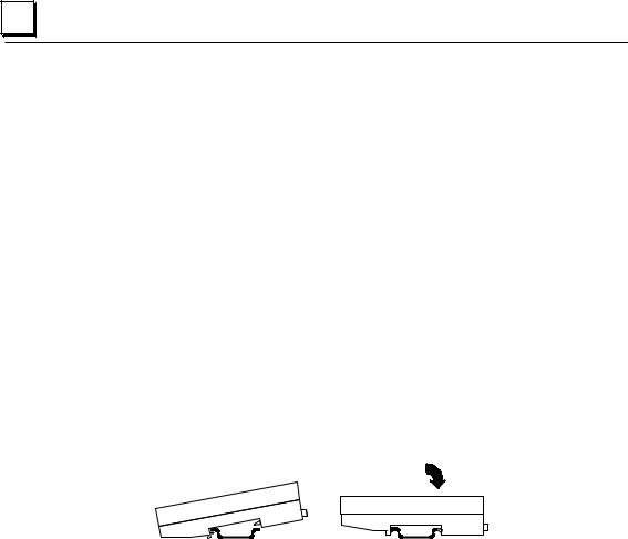
4.With a small flathead screwdriver, pull the DIN rail latch tab outward while tilting the other end of the module down to disengage it from the DIN rail.
2-4 |
VersaMax™ System Genius® Network Interface Unit User's Manual – November 2000 |
GFK-1535A |
2 |
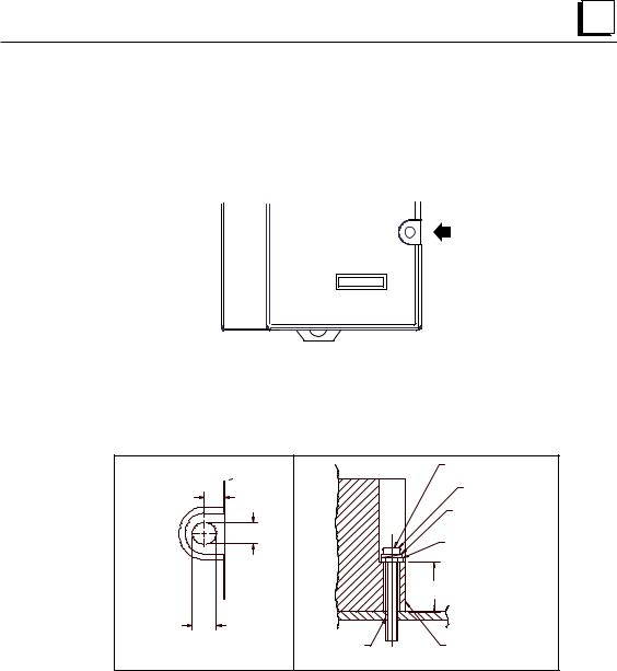
Panel-Mounting
For maximum resistance to mechanical vibration and shock, the DIN-rail-mounted module must also be installed on a panel. Using the module as a template, mark the location of the module’s panel-mount hole on the panel. Drill the hole in the panel. Install the module using an M3.5 (#6) screw in the panel-mount hole.
Note 1. Tolerances on all dimensions are +/-0.13mm (0.005in) non-cumulative.
Note 2. 1.1-1.4Nm (10-12 in/lbs) of torque should be applied to M3.5 (#6-32) steel screw threaded into material containing internal threads and having a minimum thickness of 2.4mm (0.093in).
|
SEE NOTE 2. |
4.3mm |
M3.5 (#6) SCREW |
0.170in |
SPLIT LOCK |
|
|
|
WASHER |
|
FLAT WASHER |
4.3mm
0.170in 15.9mm 0.62in REF
5.1mm
0.200in
TAPPED
HOLE IN NIU PANEL
GFK-1535A |
Chapter 2 Installation |
2-5 |

2 |
Installing an Expansion Transmitter Module
If the I/O Station will have more than one expansion rack or one expansion rack that uses an Isolated Expansion Receiver Module (IC200ERM001) as its interface to the expansion bus, an Expansion Transmitter Module must be installed to the left of the NIU. The Expansion Transmitter Module must be installed on the same section of DIN rail as the rest of the modules in the main “rack” (rack 0).
Expansion Transmitter Module
NIU and Power Supply
ETM PS
NIU
VersaMax I/O Station Main Rack (0)
1.Make sure rack power is off.
2.Attach the Expansion Transmitter to DIN rail to the left of the NIU position.
3.Install the NIU as instructed. Connect the modules and press them together until the connectors are mated.
4.After completing any additional system installation steps, apply power and observe the module LEDs.
On indicates presence of 5VDC power.
Off indicates no 5VDC power.
PWR
EXP TX
Blinking or On indicates active communications on expansion bus.
Off indicates no communications.
Removing an Expansion Transmitter Module
1.Make sure rack power is off.
2.Slide module on DIN rail away from the NIU in the main rack.
3.Using a small screwdriver, pull down on the tab on the bottom of the module and lift the module off the DIN rail.
2-6 |
VersaMax™ System Genius® Network Interface Unit User's Manual – November 2000 |
GFK-1535A |

2 |
Installing an Expansion Receiver Module
An Expansion Receiver Module (IC200ERM001 or 002) must be installed in the leftmost slot of each VersaMax expansion “rack”.
1.Insert the label inside the access door at the upper left corner of the module.
2.Attach the module to the DIN rail at the left end of the expansion rack.
3.Select the expansion rack ID (1 to 7) using the rotary switch under the access door at upper left corner of the module. Duplicate Rack IDs are not permitted. In a single-ended expansions system, the receiver Rack ID must be set to 1.
0 1 2
7  3
3
6 5 4
4.Install the Power Supply module on top of the Expansion Receiver.
5.Attach the cables. If the system includes an Expansion Transmitter Module, attach the terminator plug to the EXP2 port on the last Expansion Receiver Module.
6.After completing any additional system installation steps, apply power and observe the module LEDs.
On indicates presence of 5VDC power.
PWR
SCAN
EXP RX
Green indicates CPU/NIU is OK, has been configuredm and is being scanned.
Amber indicates not scanning.
Blinking or On indicates module is communicating on expansion bus
Off indicates module not communicating
Removing an Expansion Receiver Module
1.Make sure rack power is off.
2.Un-install the Power Supply module from the Expansion Receiver Module.
3.Slide the Expansion Receiver Module on DIN rail away from the other modules.
4.Using a small screwdriver, pull down on the tab on the bottom of the module and lift the module off the DIN rail.
Expansion Rack Power Sources
Power for module operation comes from the Power Supply installed on the Expansion Receiver Module. If the expansion rack includes any Power Supply Booster Carrier and additional rack Power Supply, it must be tied to the same source as the Power Supply on the Expansion Receiver Module.
GFK-1535A |
Chapter 2 Installation |
2-7 |

2 |
2-8
Connecting the Expansion Cable: RS-485 Differential
For a multiple-rack expansion system, connect the cable from the expansion port on the Expansion Transmitter to the Expansion Receivers as shown below. If all the Expansion Receivers are the Isolated type (IC200ERM001), the maximum overall cable length is 750 meters. If the expansion bus includes non-isolated Expansion Receivers (IC200ERM002), the maximum overall cable length is 15 meters.
VersaMax PLC or I/O Station Main Rack (0)
ETM |
PS |
|
|
|
|
|
|
|
CPU/NIU 
15M with any IC200ERM002 ERMs
750M with all IC200ERM001 ERMs
VersaMax ExpansionRack 1 |
PS |
ERM |
VersaMax ExpansionRack 7
PS
Terminator
Plug
ERM
Install the Terminator Plug (supplied with the Expansion Transmitter module) into the lower port on the last Expansion Receiver. Spare Terminator Plugs can be purchased separately as part number IC200ACC201 (Qty 2).
Note: Do not disconnect an expansion cable while the system is operating. It will cause momentary disruptions in bus communications.
RS-485 Differential Inter-Rack Connection (IC200CBL601, 602, 615)
|
PIN |
|
PIN |
|
|
|
|
2 |
FRAME+ |
2 |
FRAME+ |
|
|
|
3 |
FRAME- |
3 |
FRAME- |
|
|
Expansion |
5 |
RIRQ/+ |
5 |
RIRQ/+ |
Expansion |
|
6 |
RIRQ/- |
6 |
RIRQ/- |
|||
Transmitter or |
8 |
RUN+ |
8 |
RUN+ |
Transmitter |
|
Expansion |
9 |
RUN- |
9 |
RUN- |
or |
|
Receiver |
12 |
RERR+ |
12 |
RERR+ |
Expansion |
|
13 |
RERR- |
13 |
RERR- |
|||
Module |
Receiver |
|||||
16 |
IODT+ |
16 |
IODT+ |
|||
Transmitting |
17 |
IODT- |
17 |
IODT- |
Module |
|
Port |
20 |
RSEL+ |
20 |
RSEL+ |
Receiving |
|
21 |
RSEL- |
21 |
RSEL- |
|||
|
Port |
|||||
|
24 |
IOCLK+ |
24 |
IOCLK+ |
||
|
25 |
IOCLK- |
25 |
IOCLK- |
|
|
|
7 |
0V |
7 |
0V |
|
|
|
23 |
0V |
23 |
0V |
|
|
|
1 |
SHIELD |
1 |
SHIELD |
|
|
|
|
|
VARIABLE (SEE |
|
|
|
26-PIN |
|
26-PIN |
TEXT) |
26-PIN |
26-PIN |
|
|
|
|||||
FEMALE |
|
MALE |
|
MALE |
FEMALE |
Building a Custom Expansion Cable
Custom expansion cables can be built using Connector Kit IC200ACC202, Crimper AMP 90800-1, and Belden 8138, Manhattan/CDT M2483, Alpha 3498C, or equivalent AWG #28 (0.089mm2) cable.
VersaMax™ System Genius® Network Interface Unit User's Manual – November 2000 |
GFK-1535A |

2 |
Connecting the Expansion Cable: Single-ended
For a system with one non-isolated expansion rack (IC200ERM002) and NO Expansion Transmitter, connect the expansion cable from the serial port on the VersaMax NIU to the Expansion Receiver as shown below. The maximum cable length is one meter. Cables cannot be fabricated for this type of installation; cable IC200CBL600 must be ordered separately. Note: Do not disconnect an expansion cable while the system is operating. It will cause momentary disruptions in bus communications.
VersaMax PLC or NIU I/O Station Main Rack
PS
CPU/NIU 
1 M
VersaMax Expansion Rack
PS |
ERM |
No Terminator Plug is needed in a single-ended installation; however, it will not impede system operation if installed.
Single-Ended Inter-Rack Connection (IC200CBL600)
|
|
|
|
|
PIN |
|
VersaMax |
|
16 |
15 |
|
1 |
0V |
|
|
|
|
2 |
T_IOCLK |
|
CPU or NIU |
|
|
|
|
3 |
T_RUN |
|
|
|
|
6 |
T_IODT_ |
|
Serial Port |
|
|
|
|
9 |
T_RERR |
|
|
|
|
|||
|
|
|
|
|
10 |
T_RIRQ_ |
|
|
|
|
|
12 |
T_FRAME |
|
|
|
|
|
16 |
T_RSEL |
|
|
2 |
1 |
|
||
|
|
|
|
|
14 |
0V |
|
|
|
|
|
|
|
PIN |
|
|
|
4 |
SINGLE_ |
Expansion |
|
7 |
0V |
||
22 |
T_IOCLK |
Receiver |
|
14 |
T_RUN |
||
18 |
T_IODT_ |
IC200ERM002 |
|
15 |
T_RERR |
Receiving |
|
11 |
T_RIRQ_ |
||
Port |
|||
10 |
T_FRAME |
||
19 |
T_RSEL |
|
|
23 |
0V |
|
|
1 |
SHIELD |
|
|
1 M |
|
|
16-PIN |
16-PIN |
26-PIN |
26-PIN |
MALE |
FEMALE |
MALE |
FEMALE |
Power Sources for Single-Ended Expansion Rack Systems
When operating the system in single-ended mode, the power supplies for the main rack and expansion rack must be fed from the same main power source. The main rack and expansion racks cannot be switched ON and OFF separately; either both must be ON or both must be OFF for proper operation.
Power for module operation comes from the Power Supply installed on the Expansion Receiver Module. If the expansion rack includes any Power Supply Booster Carrier and additional rack Power Supply, it must be tied to the same source as the Power Supply on the Expansion Receiver Module.
GFK-1535A |
Chapter 2 Installation |
2-9 |
2 |
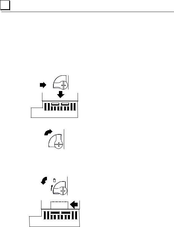
Installing Power Supply Modules
Power supply modules install directly onto the NIU module, Expansion Receiver Modules, and supplementary power supply carriers. The power supply provides +5V and +3.3V to downstream modules through the mating connector. The number of modules that can be supported depends on the power requirements of the modules. Additional booster power supplies can be used as needed to meet the power needs of all modules. The configuration software provides power calculations with a valid hardware configuration. If a rack includes more than one power supply, additional power supplies must be installed so that they can be turned at the same time as the main power supply.
1. The latch on the power supply must be in the unlocked position.
2. Align the connectors and the latch post and press the power supply module down firmly, until the two tabs on the bottom of the power supply click into place. Be sure the tabs are fully inserted in the holes in bottom edge of the NIU, ERM, or carrier.
3. Turn the latch to the locked position to secure the power supply.
Removing the Power Supply
Exercise care when working around operating equipment. Devices may become very hot and could cause injury.
1. Remove power.
2. Turn the latch to the unlocked position as illustrated.
3. Press the flexible panel on the lower edge of the power supply to disengage the tabs on the power supply from the holes in the carrier.
4. Pull the power supply straight off.
2-10 |
VersaMax™ System Genius® Network Interface Unit User's Manual – November 2000 |
GFK-1535A |
Loading...