

Page 1

GE Fanuc Automation
Computer Numerical Control Products
PMC
Model PA1/PA3/SA1/SA2/SA3/SA5/
SB/SB2/SB3/SB4/SB5/SB6/SB7/
SC/SC3/SC4/NB/NB2/NB6
Ladder Language Programming Manual, GFZ-61863E/15,
Vol. 1 of 4
February 2005
Page 2

GFL-002
Warnings, Cautions, and Notes
as Used in this Publication
Warning
Warning notices are used in this publication to emphasize that hazardous voltages,
currents, temperatures, or other conditions that could cause personal injury exist in this
equipment or may be associated with its use.
In situations where inattention could cause either personal injury or damage to equipment,
a Warning notice is used.
Caution
Caution notices are used where equipment might be damaged if care is not taken.
Note
Notes merely call attention to information that is especially significant to understanding and
operating the equipment.
This document is based on information available at the time of its publication. While efforts
have been made to be accurate, the information contained herein does not purport to cover all
details or variations in hardware or software, nor to provide for every possible contingency in
connection with installation, operation, or maintenance. Features may be described herein
which are not present in all hardware and software systems. GE Fanuc Automation assumes no
obligation of notice to holders of this document with respect to changes subsequently made.
GE Fanuc Automation makes no representation or warranty, expressed, implied, or statutory
with respect to, and assumes no responsibility for the accuracy, completeness, sufficiency, or
usefulness of the information contained herein. No warranties of merchantability or fitness for
purpose shall apply.
The following are trademarks of GE Fanuc Automation, Inc.
Alarm Master Genius ProLoop Series Six
CIMPLICITY Helpmate PROMACRO Series Three
CIMPLICITY 90–ADS Logicmaster PowerMotion VersaMax
CIMSTAR Modelmaster PowerTRAC VersaPoint
Field Control Motion Mate Series 90 VersaPro
GEnet PACSystems Series Five VuMaster
Proficy Series One Workmaster
©Copyright 2005 GE Fanuc Automation North America, Inc.
All Rights Reserved
Page 3

B–61863E/15
DEFINITION OF WARNING, CAUTION, AND NOTE
DEFINITION OF WARNING, CAUTION, AND NOTE
This manual includes safety precautions for protecting the user and preventing damage to the
machine. Precautions are classified into W arning and Caution according to their bearing on safety.
Also, supplementary information is described as a Note. Read the Warning, Caution, and Note
thoroughly before attempting to use the machine.
WARNING
Applied when there is a danger of the user being injured or when there is a danger of both the user
being injured and the equipment being damaged if the approved procedure is not observed.
CAUTION
Applied when there is a danger of the equipment being damaged, if the approved procedure is not
observed.
NOTE
The Note is used to indicate supplementary information other than Warning and Caution.
` Read this manual carefully, and store it in a safe place.
s–1
Page 4

Page 5

B–61863E/15
PREFACE
PREFACE
This programming manual describes the method of generating
ladder sequence programs for PMC.
It also describes the operation methods of CRT/MDI and
SYSTEM P series for sequence programming.
Renaming of PMC
Models
Applicable models
FANUC PMC–MODEL P A1 PMC–PA1 FANUC Power Mate–MODEL D
FANUC PMC–MODEL P A3 PMC–PA3 F ANUC Power Mate–MODEL D/F/H
FANUC PMC–MODEL SA1 (Note 1)
(Old Name : FANUC PMC–MODEL RA1)
FANUC PMC–MODEL SA2 (Note 1)
(Old Name : FANUC PMC–MODEL RA2)
This manual presents programming descriptions for the PMC
models listed in the following table. Note that some models have
been renamed; in the product name column, the old names are
enclosed in parentheses, while the new names appear above the
old names. However , the previous specifications are still applied
to the renamed models. Thus, when using the renamed models,
users should:
• Read the old names shown in this manual as the new names.
• Read the old names appearing on the units as the new names.
The models covered by this manual, and their abbreviations are :
Product Name Abbreviations Applicable CNC
FANUC Series 21–MODEL A
FANUC Series 21–MODEL A
PMC–SA1
(PMC–RA1)
PMC–SA2
(PMC–RA2)
FANUC Series 18–MODEL A/B
FANUC Series 20–MODEL A
FANUC Series 21–MODEL B
FANUC Series 20i–MODEL A
FANUC Series 0i–MODEL A
FANUC Series 21i–MODEL A/B
Loader control function (Note 2)
FANUC Series 18–MODEL A
FANUC PMC–MODEL SA3 (Note 1)
(Old Name : FANUC PMC–MODEL RA3)
FANUC PMC–MODEL SA5 (Note 1)
(Old Name : FANUC PMC–MODEL RA5)
FANUC PMC–MODEL SB (Note 1)
(Old Name : FANUC PMC–MODEL RB)
FANUC PMC–MODEL SB2 (Note 1)
(Old Name : FANUC PMC–MODEL RB2)
FANUC PMC–MODEL SB3 (Note 1)
(Old Name : FANUC PMC–MODEL RB3)
PMC–SA3
(PMC–RA3)
PMC–SA5
(PMC–RA5)
PMC–SB
(PMC–RB)
PMC–SB2
(PMC–RB2)
PMC–SB3
(PMC–RB3)
p–1
FANUC Series 18–MODEL A
FANUC Series 20–MODEL A
FANUC Series 21–MODEL B
FANUC Series 0i–MODEL A
FANUC Series 21i–MODEL A
FANUC Series 16–MODEL A
FANUC Series 16–MODEL A/B
FANUC Series 18–MODEL B
Page 6

PREFACE
Product Name Applicable CNCAbbreviations
FANUC PMC–MODEL SB4 (Note 1)
(Old Name : FANUC PMC–MODEL RB4)
FANUC PMC–MODEL SB5 (Note 1)
(Old Name : FANUC PMC–MODEL RB5)
FANUC PMC–MODEL SB6 (Note 1)
(Old Name : FANUC PMC–MODEL RB6)
FANUC PMC–MODEL SB7 PMC–SB7 FANUC Series 16i–MODEL B
FANUC PMC–MODEL SC (Note 1)
(Old Name : FANUC PMC–MODEL RC)
PMC–SB4
(PMC–RB4)
PMC–SB5
(PMC–RB5)
PMC–SB6
(PMC–RB6)
PMC–SC
(PMC–RC)
FANUC Series 16–MODEL B
FANUC Series 18–MODEL B
FANUC Series 16–MODEL C
FANUC Series 18–MODEL C
FANUC Series 16i–MODEL A
FANUC Series 18i–MODEL A
FANUC Power Mate i–MODEL D/H
FANUC Series 16–MODEL C
FANUC Series 18–MODEL C
FANUC Series 16i–MODEL A
FANUC Series 18i–MODEL A
FANUC Series 21i–MODEL A
FANUC Power Mate i–MODEL D/H
FANUC Series 18i–MODEL B
FANUC Series 21i–MODEL B
FANUC Series 16–MODEL A
B–61863E/15
FANUC PMC–MODEL SC3 (Note 1)
(Old Name : FANUC PMC–MODEL RC3)
FANUC PMC–MODEL SC4 (Note 1)
(Old Name : FANUC PMC–MODEL RC4)
FANUC PMC–MODEL NB PMC–NB FANUC Series 15–MODEL B
FANUC PMC–MODEL NB2 PMC–NB2
FANUC PMC–MODEL NB6 PMC–NB6 FANUC Series 15i–MODEL A
PMC–SC3
(PMC–RC3)
PMC–SC4
(PMC–RC4)
FANUC Series 16–MODEL A/B/C
FANUC Series 18–MODEL B/C
FANUC Series 16–MODEL B/C
FANUC Series 18–MODEL B/C
FANUC Series 15i–MODEL B
NOTE
1 These models have been renamed; in the product name
column, the old names are enclosed in parentheses, while
the new names appear above the old names. However, the
previous specifications are still applied to the renamed
models.
Thus, when using the renamed models, users should :
• Read the old names shown in this manual as the new
names.
• Read the old names appearing on the units as the new
names.
2 PMC–SA1 is applied to the loader control side of a CNC
having the loader control function.
The CNC models having the loader control function are as
follows :
FANUC Series 16–MODEL A/B/C
FANUC Series 18–MODEL A/B/C
FANUC Series 21–MODEL B
FANUC Series 16i/18i/21i–MODEL A/B
p–2
Page 7

B–61863E/15
PREFACE
Other manuals
FANUC Power Mate-MODEL D/F
CONNECTION MANUAL (B-62833EN)
FANUC Power Mate-MODEL H
CONNECTION MANUAL (B–62683EN)
FANUC Power Mate i-MODEL D/H
CONNECTION MANUAL (FUNCTION) (B–63733EN–1)
FANUC Series 16/18
CONNECTION MANUAL (B-61803E)
FANUC Series 16/18/160/180-MODEL B
CONNECTION MANUAL (FUNCTION) (B-62443E-1)
FANUC Series 16/18/160/180-MODEL C
CONNECTION MANUAL (FUNCTION) (B-62753EN-1)
FANUC Series 16i/18i/21i/160i/180i/210i–MODEL A
CONNECTION MANUAL (FUNCTION) (B-63003EN-1)
FANUC Series 16i/18i/21i/160i/180i/210i–MODEL B
CONNECTION MANUAL (FUNCTION) (B-63523EN-1)
FANUC Series 20–FA/TA
CONNECTION MANUAL (B–62173E)
FANUC Series 21/210–MODEL B
CONNECTION MANUAL (FUNCTION) (B–62703EN–1)
FANUC Series 15-MODEL B
BMI INTERFACE
CONNECTION MANUAL (B-62073E-1)
FANUC Series 15i/150i-MODEL A
CONNECTION MANUAL (FUNCTION) (B–63323EN–1)
FANUC PMC
C LANGUAGE PROGRAMMING MANUAL
(B-61863E-1)
However, it does not include all items required for sequence
programming. For those required for sequence programming
refer to the following manuals.
Name of manual Reference items Application
Interface between PMC and CNC PMC-PA1
PMC-PA3
Interface between PMC and CNC PMC-PA3
Interface between PMC and CNC PMC-SB5
PMC-SB6
Interface between PMC and CNC PMC-SA1
PMC-SA2
PMC-SA3
PMC-SB
PMC-SB2
PMC-SB3
PMC-SC
PMC-SC3
Interface between PMC and CNC PMC-SB3
PMC-SB4
PMC-SC3
PMC-SC4
Interface between PMC and CNC PMC-SB5
PMC-SB6
PMC-SC3
PMC-SC4
Interface between PMC and CNC PMC-SA1
PMC-SA5
PMC-SB5
PMC-SB6
Interface between PMC and CNC PMC-SB7
Interface between PMC and CNC PMC-SA1
PMC-SA3
Interface between PMC and CNC PMC-SA1
PMC-SA3
Interface between PMC and CNC PMC-NB
PMC-NB2
Interface between PMC and CNC PMC-NB6
C language programming PMC-SC
PMC-SC3
PMC-SC4
PMC-NB
PMC-NB2
Other application
model names
The models covered for reference by this manual, and their
abbreviations are:
Product name Abbreviation CNC for
FANUC PMC-MODEL P PMC-P FANUC Power Mate-MODEL C
FANUC PMC-MODEL NA PMC-NA FANUC Series 15-MODEL B
p–3
Page 8

Page 9

B–61863E/15
Table of Contents
Volume 1
DEFINITION OF WARNING, CAUTION, AND NOTE S–1. . . . . . . . . . . . . . . . . . . . . . . . . . . . .
PREFACE P–I. . . . . . . . . . . . . . . . . . . . . . . . . . . . . . . . . . . . . . . . . . . . . . . . . . . . . . . . . . . . . . . . . . . .
I. PMC SEQUENCE PROGRAM
1. SEQUENCE PROGRAM CREATING PROCEDURE 3. . . . . . . . . . . . . . . . . . . . . . . . . . . . . .
1.1 SPECIFICATION OF PMCs 5. . . . . . . . . . . . . . . . . . . . . . . . . . . . . . . . . . . . . . . . . . . . . . . . . . . . . . . . .
1.2 SUMMARY OF SPECIFICATION OF LADDER PROGRAM 29. . . . . . . . . . . . . . . . . . . . . . . . . . . . .
1.3 WHAT IS A SEQUENCE PROGRAM? 36. . . . . . . . . . . . . . . . . . . . . . . . . . . . . . . . . . . . . . . . . . . . . . .
1.4 CREATION OF INTERFACE SPECIFICATIONS (STEPS 1 TO 3) 38. . . . . . . . . . . . . . . . . . . . . . . . .
1.5 CREATION OF LADDER DIAGRAM (STEP 4) 38. . . . . . . . . . . . . . . . . . . . . . . . . . . . . . . . . . . . . . . .
1.6 CODING (STEP 5) 39. . . . . . . . . . . . . . . . . . . . . . . . . . . . . . . . . . . . . . . . . . . . . . . . . . . . . . . . . . . . . . .
1.7 SEQUENCE PROGRAM ENTRY (STEPS 6, 7) 40. . . . . . . . . . . . . . . . . . . . . . . . . . . . . . . . . . . . . . . .
1.8 SEQUENCE PROGRAM CHECK AND WRITE INTO ROM (STEPS 8 TO 11) 40. . . . . . . . . . . . . .
1.9 STORAGE AND CONTROL OF SEQUENCE PROGRAM (STEPS 12 TO 14) 41. . . . . . . . . . . . . . .
2. SEQUENCE PROGRAM 42. . . . . . . . . . . . . . . . . . . . . . . . . . . . . . . . . . . . . . . . . . . . . . . . . . . . .
2.1 EXECUTION PROCEDURE OF SEQUENCE PROGRAM 43. . . . . . . . . . . . . . . . . . . . . . . . . . . . . . .
2.2 REPETITIVE OPERATION 44. . . . . . . . . . . . . . . . . . . . . . . . . . . . . . . . . . . . . . . . . . . . . . . . . . . . . . . .
2.3 PRIORITY OF EXECUTION (1ST LEVEL, 2ND LEVEL AND 3RD LEVEL) 45. . . . . . . . . . . . . . .
2.4 SEQUENCE PROGRAM STRUCTURING 49. . . . . . . . . . . . . . . . . . . . . . . . . . . . . . . . . . . . . . . . . . . .
2.5 PROCESSING I/O SIGNALS 51. . . . . . . . . . . . . . . . . . . . . . . . . . . . . . . . . . . . . . . . . . . . . . . . . . . . . . .
2.5.1 Input Signal Processing 52. . . . . . . . . . . . . . . . . . . . . . . . . . . . . . . . . . . . . . . . . . . . . . . . . . . . . . . .
2.5.2 Output Signal Processing 52. . . . . . . . . . . . . . . . . . . . . . . . . . . . . . . . . . . . . . . . . . . . . . . . . . . . . .
2.5.3 I/O Signals to CNC 53. . . . . . . . . . . . . . . . . . . . . . . . . . . . . . . . . . . . . . . . . . . . . . . . . . . . . . . . . . .
2.5.4 Difference of Status of Signals between 1st Level and 2nd Level 54. . . . . . . . . . . . . . . . . . . . . . .
2.5.5 Notes on Input/Output Signals Over a Network 55. . . . . . . . . . . . . . . . . . . . . . . . . . . . . . . . . . . . .
2.6 INTERLOCKING 56. . . . . . . . . . . . . . . . . . . . . . . . . . . . . . . . . . . . . . . . . . . . . . . . . . . . . . . . . . . . . . . .
2.7 SEQUENCE PROGRAM PROCESSING TIME 57. . . . . . . . . . . . . . . . . . . . . . . . . . . . . . . . . . . . . . . .
2.8 SEQUENCE PROGRAM MEMORY CAPACITY 59. . . . . . . . . . . . . . . . . . . . . . . . . . . . . . . . . . . . . . .
3. ADDRESS 61. . . . . . . . . . . . . . . . . . . . . . . . . . . . . . . . . . . . . . . . . . . . . . . . . . . . . . . . . . . . . . . . .
3.1 ADDRESSES BETWEEN PMC AND CNC (PMC´NC) 79. . . . . . . . . . . . . . . . . . . . . . . . . . . . . . . . .
3.2 ADDRESSES BETWEEN PMC AND MACHINE TOOL (PMC´MT) 80. . . . . . . . . . . . . . . . . . . . . .
3.2.1 Addresses Between PMC and Machine Tool 80. . . . . . . . . . . . . . . . . . . . . . . . . . . . . . . . . . . . . . .
3.2.2 Assignment of I/O Module Addresses 82. . . . . . . . . . . . . . . . . . . . . . . . . . . . . . . . . . . . . . . . . . . .
3.2.3 I/O Link Connection Unit Assignment 89. . . . . . . . . . . . . . . . . . . . . . . . . . . . . . . . . . . . . . . . . . . .
3.2.4 I/O Unit MODEL B Assignment 91. . . . . . . . . . . . . . . . . . . . . . . . . . . . . . . . . . . . . . . . . . . . . . . .
3.2.5 Power Mate Assignment 92. . . . . . . . . . . . . . . . . . . . . . . . . . . . . . . . . . . . . . . . . . . . . . . . . . . . . . .
3.2.6 FS16i–LA Assignment 93. . . . . . . . . . . . . . . . . . . . . . . . . . . . . . . . . . . . . . . . . . . . . . . . . . . . . . . .
c–1
Page 10

Table of contents
3.2.7 Distribution I/O Connection I/O Module and
Distribution I/O Operator’s Panel I/O Module Assignment Methods 94. . . . . . . . . . . . . . . . . . . .
3.2.8 Assignment of Built–in I/O Card 100. . . . . . . . . . . . . . . . . . . . . . . . . . . . . . . . . . . . . . . . . . . . . . .
3.3 INTERNAL RELAY ADDRESSES (R) 101. . . . . . . . . . . . . . . . . . . . . . . . . . . . . . . . . . . . . . . . . . . . . .
3.3.1 Area Managed by the System Program 103. . . . . . . . . . . . . . . . . . . . . . . . . . . . . . . . . . . . . . . . . .
3.4 ADDRESSES FOR MESSAGE SELECTION DISPLAYED ON CRT (A) 108. . . . . . . . . . . . . . . . . . .
3.5 ADDRESS OF COUNTER (C) 110. . . . . . . . . . . . . . . . . . . . . . . . . . . . . . . . . . . . . . . . . . . . . . . . . . . . .
3.6 ADDRESS OF KEEP RELAY AND NONVOLATILE MEMORY CONTROL (K) 112. . . . . . . . . . . .
3.7 ADDRESS OF DATA TABLE (D) 114. . . . . . . . . . . . . . . . . . . . . . . . . . . . . . . . . . . . . . . . . . . . . . . . . .
3.8 TIMER ADDRESSES (T) 116. . . . . . . . . . . . . . . . . . . . . . . . . . . . . . . . . . . . . . . . . . . . . . . . . . . . . . . . .
3.9 LABEL ADDRESSES (JMPB, JMPC, LBL) (L) 118. . . . . . . . . . . . . . . . . . . . . . . . . . . . . . . . . . . . . . .
3.10 SUBPROGRAM NUMBERS (CALL, CALLU, SP) (P) 119. . . . . . . . . . . . . . . . . . . . . . . . . . . . . . . . .
B–61863E/15
4. PMC BASIC INSTRUCTIONS 120. . . . . . . . . . . . . . . . . . . . . . . . . . . . . . . . . . . . . . . . . . . . . . .
4.1 DETAILS OF BASIC INSTRUCTIONS 122. . . . . . . . . . . . . . . . . . . . . . . . . . . . . . . . . . . . . . . . . . . . . .
4.1.1 RD 124. . . . . . . . . . . . . . . . . . . . . . . . . . . . . . . . . . . . . . . . . . . . . . . . . . . . . . . . . . . . . . . . . . . . . . .
4.1.2 RD. NOT 125. . . . . . . . . . . . . . . . . . . . . . . . . . . . . . . . . . . . . . . . . . . . . . . . . . . . . . . . . . . . . . . . . .
4.1.3 WRT 126. . . . . . . . . . . . . . . . . . . . . . . . . . . . . . . . . . . . . . . . . . . . . . . . . . . . . . . . . . . . . . . . . . . . .
4.1.4 WRT. NOT 127. . . . . . . . . . . . . . . . . . . . . . . . . . . . . . . . . . . . . . . . . . . . . . . . . . . . . . . . . . . . . . . .
4.1.5 AND 128. . . . . . . . . . . . . . . . . . . . . . . . . . . . . . . . . . . . . . . . . . . . . . . . . . . . . . . . . . . . . . . . . . . . .
4.1.6 AND. NOT 128. . . . . . . . . . . . . . . . . . . . . . . . . . . . . . . . . . . . . . . . . . . . . . . . . . . . . . . . . . . . . . . .
4.1.7 OR 128. . . . . . . . . . . . . . . . . . . . . . . . . . . . . . . . . . . . . . . . . . . . . . . . . . . . . . . . . . . . . . . . . . . . . . .
4.1.8 OR. NOT 128. . . . . . . . . . . . . . . . . . . . . . . . . . . . . . . . . . . . . . . . . . . . . . . . . . . . . . . . . . . . . . . . . .
4.1.9 RD. STK 129. . . . . . . . . . . . . . . . . . . . . . . . . . . . . . . . . . . . . . . . . . . . . . . . . . . . . . . . . . . . . . . . . .
4.1.10 RD. NOT. STK 130. . . . . . . . . . . . . . . . . . . . . . . . . . . . . . . . . . . . . . . . . . . . . . . . . . . . . . . . . . . . .
4.1.11 AND. STK 131. . . . . . . . . . . . . . . . . . . . . . . . . . . . . . . . . . . . . . . . . . . . . . . . . . . . . . . . . . . . . . . . .
4.1.12 OR. STK 131. . . . . . . . . . . . . . . . . . . . . . . . . . . . . . . . . . . . . . . . . . . . . . . . . . . . . . . . . . . . . . . . . .
4.1.13 SET 131. . . . . . . . . . . . . . . . . . . . . . . . . . . . . . . . . . . . . . . . . . . . . . . . . . . . . . . . . . . . . . . . . . . . . .
4.1.14 RST 133. . . . . . . . . . . . . . . . . . . . . . . . . . . . . . . . . . . . . . . . . . . . . . . . . . . . . . . . . . . . . . . . . . . . . .
5. FUNCTIONAL INSTRUCTIONS 135. . . . . . . . . . . . . . . . . . . . . . . . . . . . . . . . . . . . . . . . . . . . .
5.1 END1 (1ST LEVEL SEQUENCE PROGRAM END) 167. . . . . . . . . . . . . . . . . . . . . . . . . . . . . . . . . . .
5.2 END2 (2ND LEVEL SEQUENCE PROGRAM END) 168. . . . . . . . . . . . . . . . . . . . . . . . . . . . . . . . . . .
5.3 END3 (END OF 3RD LEVEL SEQUENCE) (PMC–SC/SC3/SC4/NB/NB2/NB6/NB7 ONLY) 169. .
5.4 TMR (TIMER) 170. . . . . . . . . . . . . . . . . . . . . . . . . . . . . . . . . . . . . . . . . . . . . . . . . . . . . . . . . . . . . . . . . .
5.5 TMRB (FIXED TIMER) 172. . . . . . . . . . . . . . . . . . . . . . . . . . . . . . . . . . . . . . . . . . . . . . . . . . . . . . . . . .
5.6 TMRC (TIMER) 174. . . . . . . . . . . . . . . . . . . . . . . . . . . . . . . . . . . . . . . . . . . . . . . . . . . . . . . . . . . . . . . .
5.7 DEC (DECODE) 177. . . . . . . . . . . . . . . . . . . . . . . . . . . . . . . . . . . . . . . . . . . . . . . . . . . . . . . . . . . . . . . .
5.8 DECB (BINARY DECODING) 179. . . . . . . . . . . . . . . . . . . . . . . . . . . . . . . . . . . . . . . . . . . . . . . . . . . . .
5.9 CTR (COUNTER) 182. . . . . . . . . . . . . . . . . . . . . . . . . . . . . . . . . . . . . . . . . . . . . . . . . . . . . . . . . . . . . . .
5.10 CTRB (FIXED COUNTER) 188. . . . . . . . . . . . . . . . . . . . . . . . . . . . . . . . . . . . . . . . . . . . . . . . . . . . . . .
5.11 CTRC (COUNTER) 190. . . . . . . . . . . . . . . . . . . . . . . . . . . . . . . . . . . . . . . . . . . . . . . . . . . . . . . . . . . . . .
5.12 ROT (ROTATION CONTROL) 193. . . . . . . . . . . . . . . . . . . . . . . . . . . . . . . . . . . . . . . . . . . . . . . . . . . . .
5.13 ROTB (BINARY ROTATION CONTROL) 196. . . . . . . . . . . . . . . . . . . . . . . . . . . . . . . . . . . . . . . . . . .
5.14 COD (CODE CONVERSION) 199. . . . . . . . . . . . . . . . . . . . . . . . . . . . . . . . . . . . . . . . . . . . . . . . . . . . .
5.15 CODB (BINARY CODE CONVERSION) 202. . . . . . . . . . . . . . . . . . . . . . . . . . . . . . . . . . . . . . . . . . . .
5.16 MOVE (LOGICAL PRODUCT TRANSFER) 204. . . . . . . . . . . . . . . . . . . . . . . . . . . . . . . . . . . . . . . . .
c–2
Page 11

B–61863E/15
5.17 MOVOR (DATA TRANSFER AFTER LOGICAL SUM) 206. . . . . . . . . . . . . . . . . . . . . . . . . . . . . . . .
5.18 COM (COMMON LINE CONTROL) 207. . . . . . . . . . . . . . . . . . . . . . . . . . . . . . . . . . . . . . . . . . . . . . . .
5.19 COME (COMMON LINE CONTROL END) 213. . . . . . . . . . . . . . . . . . . . . . . . . . . . . . . . . . . . . . . . . .
5.20 JMP (JUMP) 214. . . . . . . . . . . . . . . . . . . . . . . . . . . . . . . . . . . . . . . . . . . . . . . . . . . . . . . . . . . . . . . . . . . .
5.21 JMPE (JUMP END) 219. . . . . . . . . . . . . . . . . . . . . . . . . . . . . . . . . . . . . . . . . . . . . . . . . . . . . . . . . . . . . .
5.22 PARI (PARITY CHECK) 220. . . . . . . . . . . . . . . . . . . . . . . . . . . . . . . . . . . . . . . . . . . . . . . . . . . . . . . . . .
5.23 DCNV (DATA CONVERSION) 222. . . . . . . . . . . . . . . . . . . . . . . . . . . . . . . . . . . . . . . . . . . . . . . . . . . .
5.24 DCNVB (EXTENDED DATA CONVERSION) 224. . . . . . . . . . . . . . . . . . . . . . . . . . . . . . . . . . . . . . . .
5.25 COMP (COMPARISON) 226. . . . . . . . . . . . . . . . . . . . . . . . . . . . . . . . . . . . . . . . . . . . . . . . . . . . . . . . . .
5.26 COMPB (COMPARISON BETWEEN BINARY DATA) 228. . . . . . . . . . . . . . . . . . . . . . . . . . . . . . . . .
5.27 COIN (COINCIDENCE CHECK) 230. . . . . . . . . . . . . . . . . . . . . . . . . . . . . . . . . . . . . . . . . . . . . . . . . . .
5.28 SFT (SHIFT REGISTER) 232. . . . . . . . . . . . . . . . . . . . . . . . . . . . . . . . . . . . . . . . . . . . . . . . . . . . . . . . .
5.29 DSCH (DATA SEARCH) 234. . . . . . . . . . . . . . . . . . . . . . . . . . . . . . . . . . . . . . . . . . . . . . . . . . . . . . . . . .
5.30 DSCHB (BINARY DATA SEARCH) 237. . . . . . . . . . . . . . . . . . . . . . . . . . . . . . . . . . . . . . . . . . . . . . . .
5.31 XMOV (INDEXED DATA TRANSFER) 239. . . . . . . . . . . . . . . . . . . . . . . . . . . . . . . . . . . . . . . . . . . . .
5.32 XMOVB (BINARY INDEX MODIFIER DATA TRANSFER) 242. . . . . . . . . . . . . . . . . . . . . . . . . . . .
5.33 ADD (ADDITION) 249. . . . . . . . . . . . . . . . . . . . . . . . . . . . . . . . . . . . . . . . . . . . . . . . . . . . . . . . . . . . . .
5.34 ADDB (BINARY ADDITION) 251. . . . . . . . . . . . . . . . . . . . . . . . . . . . . . . . . . . . . . . . . . . . . . . . . . . . .
5.35 SUB (SUBTRACTION) 253. . . . . . . . . . . . . . . . . . . . . . . . . . . . . . . . . . . . . . . . . . . . . . . . . . . . . . . . . . .
5.36 SUBB (BINARY SUBTRACTION) 255. . . . . . . . . . . . . . . . . . . . . . . . . . . . . . . . . . . . . . . . . . . . . . . . .
5.37 MUL (MULTIPLICATION) 257. . . . . . . . . . . . . . . . . . . . . . . . . . . . . . . . . . . . . . . . . . . . . . . . . . . . . . . .
5.38 MULB (BINARY MULTIPLICATION) 259. . . . . . . . . . . . . . . . . . . . . . . . . . . . . . . . . . . . . . . . . . . . . .
5.39 DIV (DIVISION) 261. . . . . . . . . . . . . . . . . . . . . . . . . . . . . . . . . . . . . . . . . . . . . . . . . . . . . . . . . . . . . . . .
5.40 DIVB (BINARY DIVISION) 263. . . . . . . . . . . . . . . . . . . . . . . . . . . . . . . . . . . . . . . . . . . . . . . . . . . . . . .
5.41 NUME (DEFINITION OF CONSTANT) 265. . . . . . . . . . . . . . . . . . . . . . . . . . . . . . . . . . . . . . . . . . . . .
5.42 NUMEB (DEFINITION OF BINARY CONSTANTS) 266. . . . . . . . . . . . . . . . . . . . . . . . . . . . . . . . . . .
5.43 DISP (MESSAGE DISPLAY) (PMC–SB/SB2/SB3/SB4/SB5/SB6/SC/SC3/SC4 ONLY) 268. . . . . . . .
5.44 DISPB 282. . . . . . . . . . . . . . . . . . . . . . . . . . . . . . . . . . . . . . . . . . . . . . . . . . . . . . . . . . . . . . . . . . . . . . . . .
5.45 EXIN (EXTERNAL DATA INPUT) 293. . . . . . . . . . . . . . . . . . . . . . . . . . . . . . . . . . . . . . . . . . . . . . . . .
5.46 WINDR (READING CNC WINDOW DATA) 299. . . . . . . . . . . . . . . . . . . . . . . . . . . . . . . . . . . . . . . . .
5.47 WINDW (WRITING CNC WINDOW DATA) 302. . . . . . . . . . . . . . . . . . . . . . . . . . . . . . . . . . . . . . . . .
5.48 ARBITRARY FUNCTIONAL INSTRUCTIONS 305. . . . . . . . . . . . . . . . . . . . . . . . . . . . . . . . . . . . . . .
5.49 MMCWR (READING MMC WINDOW DATA) (OTHER THAN PMC–PA1/PA3) 308. . . . . . . . . . .
5.50 MMCWW (WRITING MMC WINDOW DATA) (OTHER THAN PMC–PA1/PA3) 310. . . . . . . . . . .
5.51 MOVB (TRANSFER OF 1 BYTE) 312. . . . . . . . . . . . . . . . . . . . . . . . . . . . . . . . . . . . . . . . . . . . . . . . . .
5.52 MOVW (TRANSFER OF 2 BYTES) 313. . . . . . . . . . . . . . . . . . . . . . . . . . . . . . . . . . . . . . . . . . . . . . . .
5.53 MOVN (TRANSFER OF AN ARBITRARY NUMBER OF BYTES) 314. . . . . . . . . . . . . . . . . . . . . . .
5.54 MOVD (TRANSFER OF 4 BYTES) 315. . . . . . . . . . . . . . . . . . . . . . . . . . . . . . . . . . . . . . . . . . . . . . . . .
5.55 DIFU (RISING EDGE DETECTION) 316. . . . . . . . . . . . . . . . . . . . . . . . . . . . . . . . . . . . . . . . . . . . . . . .
5.56 DIFD (FALLING EDGE DETECTION) 317. . . . . . . . . . . . . . . . . . . . . . . . . . . . . . . . . . . . . . . . . . . . . .
5.57 EOR (EXCLUSIVE OR) 318. . . . . . . . . . . . . . . . . . . . . . . . . . . . . . . . . . . . . . . . . . . . . . . . . . . . . . . . . .
5.58 AND (LOGICAL AND) 320. . . . . . . . . . . . . . . . . . . . . . . . . . . . . . . . . . . . . . . . . . . . . . . . . . . . . . . . . . .
5.59 OR (LOGICAL OR) 322. . . . . . . . . . . . . . . . . . . . . . . . . . . . . . . . . . . . . . . . . . . . . . . . . . . . . . . . . . . . . .
5.60 NOT (LOGICAL NOT) 324. . . . . . . . . . . . . . . . . . . . . . . . . . . . . . . . . . . . . . . . . . . . . . . . . . . . . . . . . . .
5.61 MMC3 R (MMC–III WINDOW DATA READ) 326. . . . . . . . . . . . . . . . . . . . . . . . . . . . . . . . . . . . . . . .
5.62 MMC3W (MMC–III WINDOW DATA WRITE) 329. . . . . . . . . . . . . . . . . . . . . . . . . . . . . . . . . . . . . . .
5.63 SPCNT (SPINDLE CONTROL) 332. . . . . . . . . . . . . . . . . . . . . . . . . . . . . . . . . . . . . . . . . . . . . . . . . . . .
Table of contents
c–3
Page 12

Table of contents
5.64 END (END OF A LADDER PROGRAM) 340. . . . . . . . . . . . . . . . . . . . . . . . . . . . . . . . . . . . . . . . . . . .
5.65 CALL (CONDITIONAL SUBPROGRAM CALL) 341. . . . . . . . . . . . . . . . . . . . . . . . . . . . . . . . . . . . .
5.66 CALLU (UNCONDITIONAL SUBPROGRAM CALL) 342. . . . . . . . . . . . . . . . . . . . . . . . . . . . . . . . .
5.67 SP (SUBPROGRAM) 343. . . . . . . . . . . . . . . . . . . . . . . . . . . . . . . . . . . . . . . . . . . . . . . . . . . . . . . . . . . . .
5.68 SPE (END OF A SUBPROGRAM) 344. . . . . . . . . . . . . . . . . . . . . . . . . . . . . . . . . . . . . . . . . . . . . . . . . .
5.69 JMPB (LABEL JUMP) 345. . . . . . . . . . . . . . . . . . . . . . . . . . . . . . . . . . . . . . . . . . . . . . . . . . . . . . . . . . .
5.70 JMPC (LABEL JUMP) 346. . . . . . . . . . . . . . . . . . . . . . . . . . . . . . . . . . . . . . . . . . . . . . . . . . . . . . . . . . .
5.71 LBL (LABEL) 347. . . . . . . . . . . . . . . . . . . . . . . . . . . . . . . . . . . . . . . . . . . . . . . . . . . . . . . . . . . . . . . . . .
5.72 AXCTL (AXIS CONTROL BY PMC) 348. . . . . . . . . . . . . . . . . . . . . . . . . . . . . . . . . . . . . . . . . . . . . . .
5.73 PSGNL (POSITION SIGNAL OUTPUT) 354. . . . . . . . . . . . . . . . . . . . . . . . . . . . . . . . . . . . . . . . . . . . .
5.74 PSGN2 (POSITION SIGNAL OUTPUT 2) 358. . . . . . . . . . . . . . . . . . . . . . . . . . . . . . . . . . . . . . . . . . . .
5.75 NOP (NO OPERATION) 362. . . . . . . . . . . . . . . . . . . . . . . . . . . . . . . . . . . . . . . . . . . . . . . . . . . . . . . . .
B–61863E/15
6. NONVOLATILE MEMORY 364. . . . . . . . . . . . . . . . . . . . . . . . . . . . . . . . . . . . . . . . . . . . . . . . . .
6.1 TIMER, COUNTER, KEEP RELAY, NONVOLATILE MEMORY CONTROL, DATA TABLE 365.
6.2 READING AND WRITING OF NONVOLATILE MEMORY DATA 367. . . . . . . . . . . . . . . . . . . . . . .
6.3 PMC DATA TABLE 368. . . . . . . . . . . . . . . . . . . . . . . . . . . . . . . . . . . . . . . . . . . . . . . . . . . . . . . . . . . . . .
7. LADDER DIAGRAM FORMAT 373. . . . . . . . . . . . . . . . . . . . . . . . . . . . . . . . . . . . . . . . . . . . . .
7.1 ADDRESSES, SIGNAL NAMES, COMMENTS, AND LINE NUMBERS 374. . . . . . . . . . . . . . . . . .
7.1.1 Addresses 374. . . . . . . . . . . . . . . . . . . . . . . . . . . . . . . . . . . . . . . . . . . . . . . . . . . . . . . . . . . . . . . . . .
7.1.2 Signal Names 375. . . . . . . . . . . . . . . . . . . . . . . . . . . . . . . . . . . . . . . . . . . . . . . . . . . . . . . . . . . . . .
7.1.3 Comments 375. . . . . . . . . . . . . . . . . . . . . . . . . . . . . . . . . . . . . . . . . . . . . . . . . . . . . . . . . . . . . . . . .
7.1.4 Line Numbers 375. . . . . . . . . . . . . . . . . . . . . . . . . . . . . . . . . . . . . . . . . . . . . . . . . . . . . . . . . . . . . .
7.2 SYMBOLS USED IN THE LADDER DIAGRAM 376. . . . . . . . . . . . . . . . . . . . . . . . . . . . . . . . . . . . .
7.3 LADDER DIAGRAM FORMAT 377. . . . . . . . . . . . . . . . . . . . . . . . . . . . . . . . . . . . . . . . . . . . . . . . . . . .
7.4 INFINITE NUMBER OF RELAY CONTACTS 378. . . . . . . . . . . . . . . . . . . . . . . . . . . . . . . . . . . . . . . .
8. MISCELLANEOUS ITEM 379. . . . . . . . . . . . . . . . . . . . . . . . . . . . . . . . . . . . . . . . . . . . . . . . . . .
9. SEQUENCE PROGRAM STRUCTURING 380. . . . . . . . . . . . . . . . . . . . . . . . . . . . . . . . . . . .
9.1 EXAMPLES OF STRUCTURED PROGRAMMING 381. . . . . . . . . . . . . . . . . . . . . . . . . . . . . . . . . . .
9.1.1 Implementation Techniques 381. . . . . . . . . . . . . . . . . . . . . . . . . . . . . . . . . . . . . . . . . . . . . . . . . . .
9.1.2 Applications 382. . . . . . . . . . . . . . . . . . . . . . . . . . . . . . . . . . . . . . . . . . . . . . . . . . . . . . . . . . . . . . .
9.1.3 Specifications 384. . . . . . . . . . . . . . . . . . . . . . . . . . . . . . . . . . . . . . . . . . . . . . . . . . . . . . . . . . . . . .
9.2 SUBPROGRAMMING AND NESTING 385. . . . . . . . . . . . . . . . . . . . . . . . . . . . . . . . . . . . . . . . . . . . .
9.2.1 Function 385. . . . . . . . . . . . . . . . . . . . . . . . . . . . . . . . . . . . . . . . . . . . . . . . . . . . . . . . . . . . . . . . . . .
9.2.2 Execution Method 386. . . . . . . . . . . . . . . . . . . . . . . . . . . . . . . . . . . . . . . . . . . . . . . . . . . . . . . . . . .
9.2.3 Creating a Program 387. . . . . . . . . . . . . . . . . . . . . . . . . . . . . . . . . . . . . . . . . . . . . . . . . . . . . . . . . .
9.3 CAUTIONS FOR SUBROUTINES 389. . . . . . . . . . . . . . . . . . . . . . . . . . . . . . . . . . . . . . . . . . . . . . . . . .
10. JMP INSTRUCTIONS WITH LABEL SPECIFICATION 391. . . . . . . . . . . . . . . . . . . . . . . .
10.1 SPECIFICATIONS 392. . . . . . . . . . . . . . . . . . . . . . . . . . . . . . . . . . . . . . . . . . . . . . . . . . . . . . . . . . . . . . .
10.2 RESTRICTIONS 396. . . . . . . . . . . . . . . . . . . . . . . . . . . . . . . . . . . . . . . . . . . . . . . . . . . . . . . . . . . . . . . .
11. INTERRUPT–TYPE PMC FUNCTION 402. . . . . . . . . . . . . . . . . . . . . . . . . . . . . . . . . . . . . . .
11.1 OVERVIEW 403. . . . . . . . . . . . . . . . . . . . . . . . . . . . . . . . . . . . . . . . . . . . . . . . . . . . . . . . . . . . . . . . . . . .
c–4
Page 13

B–61863E/15
11.2 SETTING 404. . . . . . . . . . . . . . . . . . . . . . . . . . . . . . . . . . . . . . . . . . . . . . . . . . . . . . . . . . . . . . . . . . . . . .
11.3 INTERRUPT PROCESSING 405. . . . . . . . . . . . . . . . . . . . . . . . . . . . . . . . . . . . . . . . . . . . . . . . . . . . . . .
11.3.1 Interrupt Program 405. . . . . . . . . . . . . . . . . . . . . . . . . . . . . . . . . . . . . . . . . . . . . . . . . . . . . . . . . . .
11.3.2 Input/Output Signal Processing 406. . . . . . . . . . . . . . . . . . . . . . . . . . . . . . . . . . . . . . . . . . . . . . . .
11.3.3 Response Time 406. . . . . . . . . . . . . . . . . . . . . . . . . . . . . . . . . . . . . . . . . . . . . . . . . . . . . . . . . . . . .
11.3.4 Execution Time 407. . . . . . . . . . . . . . . . . . . . . . . . . . . . . . . . . . . . . . . . . . . . . . . . . . . . . . . . . . . . .
11.3.5 Interrupt Enable/Disable/Clear 407. . . . . . . . . . . . . . . . . . . . . . . . . . . . . . . . . . . . . . . . . . . . . . . . .
11.3.6 Cautions 409. . . . . . . . . . . . . . . . . . . . . . . . . . . . . . . . . . . . . . . . . . . . . . . . . . . . . . . . . . . . . . . . . . .
11.4 SEQUENCE PROGRAM EXAMPLES 411. . . . . . . . . . . . . . . . . . . . . . . . . . . . . . . . . . . . . . . . . . . . . .
Table of contents
II. PMC OPERATION (CRT/MDI)
1. GENERAL 417. . . . . . . . . . . . . . . . . . . . . . . . . . . . . . . . . . . . . . . . . . . . . . . . . . . . . . . . . . . . . . . .
1.1 FOR MDI UNITS OTHER THAN STANDARD MDI UNITS
(FOR FS20 PMC–SA1 AND SA3) 424. . . . . . . . . . . . . . . . . . . . . . . . . . . . . . . . . . . . . . . . . . . . . . . . . .
1.2 AUTOMATIC OPERATION WHEN THE POWER IS TURNED ON 424. . . . . . . . . . . . . . . . . . . . . .
1.3 CLEARING THE SEQUENCE PROGRAM 424. . . . . . . . . . . . . . . . . . . . . . . . . . . . . . . . . . . . . . . . . .
1.4 LOADING THE STANDARD LADDER (FOR Power Mate–D/F PMC–PA1 AND PA3) 425. . . . . . .
1.5 FS15i PMC–NB6 OPERATING PROCEDURE 425. . . . . . . . . . . . . . . . . . . . . . . . . . . . . . . . . . . . . . . .
1.6 FS16i/18i/21i–B PMC–SA1/SB7 OPERATING PROCEDURE 425. . . . . . . . . . . . . . . . . . . . . . . . . . . .
1.7 LADDER PASSWORD FUNCTION 426. . . . . . . . . . . . . . . . . . . . . . . . . . . . . . . . . . . . . . . . . . . . . . . .
1.8 PMC OPERATION FOR LOADER CONTROL FUNCTION 429. . . . . . . . . . . . . . . . . . . . . . . . . . . . .
2. PMC MENU SELECTION PROCEDURE BY SOFTKEY 430. . . . . . . . . . . . . . . . . . . . . . . .
3. PMC I/O SIGNAL DISPLAY AND INTERNAL RELAY DISPLAY (PMCDGN) 436. . . . . .
3.1 DISPLAYING TITLE DATA 437. . . . . . . . . . . . . . . . . . . . . . . . . . . . . . . . . . . . . . . . . . . . . . . . . . . . . . .
3.2 DISPLAY OF SIGNAL STATUS (STATUS) 439. . . . . . . . . . . . . . . . . . . . . . . . . . . . . . . . . . . . . . . . . . .
3.3 ALARM SCREEN (ALARM) 440. . . . . . . . . . . . . . . . . . . . . . . . . . . . . . . . . . . . . . . . . . . . . . . . . . . . . .
3.4 TRACE FUNCTION (TRACE) 441. . . . . . . . . . . . . . . . . . . . . . . . . . . . . . . . . . . . . . . . . . . . . . . . . . . . .
3.4.1 Operation 441. . . . . . . . . . . . . . . . . . . . . . . . . . . . . . . . . . . . . . . . . . . . . . . . . . . . . . . . . . . . . . . . . .
3.4.2 Parameter Setting Screen 441. . . . . . . . . . . . . . . . . . . . . . . . . . . . . . . . . . . . . . . . . . . . . . . . . . . . .
3.4.3 Starting or Stopping the Trace Function 442. . . . . . . . . . . . . . . . . . . . . . . . . . . . . . . . . . . . . . . . . .
3.4.4 Trace Screen 443. . . . . . . . . . . . . . . . . . . . . . . . . . . . . . . . . . . . . . . . . . . . . . . . . . . . . . . . . . . . . . .
3.4.5 Automatic Tracing Function at Power on 443. . . . . . . . . . . . . . . . . . . . . . . . . . . . . . . . . . . . . . . . .
3.5 DISPLAYING THE CONTENTS OF MEMORY (M.SRCH) 444. . . . . . . . . . . . . . . . . . . . . . . . . . . . .
3.5.1 Operation 444. . . . . . . . . . . . . . . . . . . . . . . . . . . . . . . . . . . . . . . . . . . . . . . . . . . . . . . . . . . . . . . . . .
3.5.2 Function for Storing Data in Memory 445. . . . . . . . . . . . . . . . . . . . . . . . . . . . . . . . . . . . . . . . . . .
3.6 FUNCTION FOR DISPLAYING SIGNAL WAVEFORMS (ANALYS) 446. . . . . . . . . . . . . . . . . . . . .
3.6.1 Specifications 446. . . . . . . . . . . . . . . . . . . . . . . . . . . . . . . . . . . . . . . . . . . . . . . . . . . . . . . . . . . . . .
3.6.2 Operation 446. . . . . . . . . . . . . . . . . . . . . . . . . . . . . . . . . . . . . . . . . . . . . . . . . . . . . . . . . . . . . . . . . .
3.6.3 Parameter Screen 447. . . . . . . . . . . . . . . . . . . . . . . . . . . . . . . . . . . . . . . . . . . . . . . . . . . . . . . . . . . .
3.6.4 Signal Diagnosis Screen 450. . . . . . . . . . . . . . . . . . . . . . . . . . . . . . . . . . . . . . . . . . . . . . . . . . . . . .
3.6.5 Reading Signals Automatically at Power on 451. . . . . . . . . . . . . . . . . . . . . . . . . . . . . . . . . . . . . .
3.7 DISPLAYING THE RUNNING STATE OF A USER TASK (USRDGN) 452. . . . . . . . . . . . . . . . . . . .
c–5
Page 14

Table of contents
3.8 DISPLAYING AND SETTING THE CONFIGURATION STATUS OF I/O
DEVICES (IOCHK) 454. . . . . . . . . . . . . . . . . . . . . . . . . . . . . . . . . . . . . . . . . . . . . . . . . . . . . . . . . . . . . .
3.8.1 I/O Link Connecting Check Screen 456. . . . . . . . . . . . . . . . . . . . . . . . . . . . . . . . . . . . . . . . . . . . .
3.8.2 I/O Link–II Parameter Setting Screen 458. . . . . . . . . . . . . . . . . . . . . . . . . . . . . . . . . . . . . . . . . . .
3.9 FORCED INPUT/OUTPUT FUNCTION 461. . . . . . . . . . . . . . . . . . . . . . . . . . . . . . . . . . . . . . . . . . . . .
3.9.1 Overview 461. . . . . . . . . . . . . . . . . . . . . . . . . . . . . . . . . . . . . . . . . . . . . . . . . . . . . . . . . . . . . . . . . .
3.9.2 Setting/Operation for Enabling Forced Input/Output 465. . . . . . . . . . . . . . . . . . . . . . . . . . . . . . . .
3.9.3 Screen Display 466. . . . . . . . . . . . . . . . . . . . . . . . . . . . . . . . . . . . . . . . . . . . . . . . . . . . . . . . . . . . .
3.9.4 Modifying the Values of Signals by Forced Input/Output 469. . . . . . . . . . . . . . . . . . . . . . . . . . . .
3.9.5 Setting/Clearing OVERRIDE 470. . . . . . . . . . . . . . . . . . . . . . . . . . . . . . . . . . . . . . . . . . . . . . . . . .
B–61863E/15
4. PMC PARAMETERS SETTING AND DISPLAY (PMCPRM) 472. . . . . . . . . . . . . . . . . . . . .
4.1 OUTLINE 473. . . . . . . . . . . . . . . . . . . . . . . . . . . . . . . . . . . . . . . . . . . . . . . . . . . . . . . . . . . . . . . . . . . . . .
4.2 INPUT PMC PARAMETERS FROM MDI PANEL 474. . . . . . . . . . . . . . . . . . . . . . . . . . . . . . . . . . . . .
4.2.1 Multiple Data Input 474. . . . . . . . . . . . . . . . . . . . . . . . . . . . . . . . . . . . . . . . . . . . . . . . . . . . . . . . . .
4.3 SETTING AND DISPLAY SCREEN 475. . . . . . . . . . . . . . . . . . . . . . . . . . . . . . . . . . . . . . . . . . . . . . . .
4.3.1 Timer Screen (TIMER) 475. . . . . . . . . . . . . . . . . . . . . . . . . . . . . . . . . . . . . . . . . . . . . . . . . . . . . . .
4.3.2 Counter Screen (COUNTR) 476. . . . . . . . . . . . . . . . . . . . . . . . . . . . . . . . . . . . . . . . . . . . . . . . . . .
4.3.3 Keep Relay (KEEPRL) 476. . . . . . . . . . . . . . . . . . . . . . . . . . . . . . . . . . . . . . . . . . . . . . . . . . . . . . .
4.3.4 Data Table (DATA) 482. . . . . . . . . . . . . . . . . . . . . . . . . . . . . . . . . . . . . . . . . . . . . . . . . . . . . . . . . .
4.4 SETTING SCREEN 484. . . . . . . . . . . . . . . . . . . . . . . . . . . . . . . . . . . . . . . . . . . . . . . . . . . . . . . . . . . . . .
4.4.1 Other Setting Screens 487. . . . . . . . . . . . . . . . . . . . . . . . . . . . . . . . . . . . . . . . . . . . . . . . . . . . . . . .
4.5 NOTE 490. . . . . . . . . . . . . . . . . . . . . . . . . . . . . . . . . . . . . . . . . . . . . . . . . . . . . . . . . . . . . . . . . . . . . . . . .
5. PMC LADDER DIAGRAM DISPLAY (PMCLAD) 491. . . . . . . . . . . . . . . . . . . . . . . . . . . . . . .
5.1 LADDER DIAGRAM DISPLAY 492. . . . . . . . . . . . . . . . . . . . . . . . . . . . . . . . . . . . . . . . . . . . . . . . . . .
5.2 DUMP DISPLAY ON LADDER DIAGRAM 493. . . . . . . . . . . . . . . . . . . . . . . . . . . . . . . . . . . . . . . . . .
5.3 PARAMETER DISPLAY ON LADDER DIAGRAM 494. . . . . . . . . . . . . . . . . . . . . . . . . . . . . . . . . . . .
5.3.1 The Value of Functional Instruction Parameter 495. . . . . . . . . . . . . . . . . . . . . . . . . . . . . . . . . . . .
5.4 SYMBOL AND COMMENT DISPLAY 497. . . . . . . . . . . . . . . . . . . . . . . . . . . . . . . . . . . . . . . . . . . . . .
5.5 SEARCH OF SPECIFIED RELAY COIL POINTS IN LADDER DIAGRAM 498. . . . . . . . . . . . . . . .
5.6 STOP OF LADDER DIAGRAM DISPLAY BY TRIGGER OF SIGNAL 499. . . . . . . . . . . . . . . . . . . .
5.7 DIVIDING DISPLAY OF LADDER DIAGRAM 501. . . . . . . . . . . . . . . . . . . . . . . . . . . . . . . . . . . . . . .
5.8 ON–LINE EDIT 503. . . . . . . . . . . . . . . . . . . . . . . . . . . . . . . . . . . . . . . . . . . . . . . . . . . . . . . . . . . . . . . . .
6. USER PMC SCREEN (PMCMDI) 504. . . . . . . . . . . . . . . . . . . . . . . . . . . . . . . . . . . . . . . . . . . .
6.1 FOR THE FS16 (PMC–SC, PMC–SC3, OR PMC–SC4) 505. . . . . . . . . . . . . . . . . . . . . . . . . . . . . . . . .
6.2 FOR THE FS15 (PMC–NB) 505. . . . . . . . . . . . . . . . . . . . . . . . . . . . . . . . . . . . . . . . . . . . . . . . . . . . . . .
III. PMC PROGRAMMER (CRT/MDI)
1. GENERAL 509. . . . . . . . . . . . . . . . . . . . . . . . . . . . . . . . . . . . . . . . . . . . . . . . . . . . . . . . . . . . . . . .
1.1 ABOUT THE FS15i PMC–NB6 PROGRAMMER 510. . . . . . . . . . . . . . . . . . . . . . . . . . . . . . . . . . . . . .
1.2 ABOUT THE FS16i/18i/21i/0i–B PMC–SA1/SB7 PROGRAMMER 510. . . . . . . . . . . . . . . . . . . . . . .
2. COMPONENT UNITS AND CONNECTIONS 511. . . . . . . . . . . . . . . . . . . . . . . . . . . . . . . . . .
2.1 COMPONENT UNITS 512. . . . . . . . . . . . . . . . . . . . . . . . . . . . . . . . . . . . . . . . . . . . . . . . . . . . . . . . . . .
c–6
Page 15

B–61863E/15
2.2 CONNECTING COMPONENT UNITS 517. . . . . . . . . . . . . . . . . . . . . . . . . . . . . . . . . . . . . . . . . . . . . .
Table of contents
3. SELECTION OF PROGRAMMER MENUS BY SOFTKEYS 518. . . . . . . . . . . . . . . . . . . . .
4. SPECIFYING AND DISPLAYING SYSTEM PARAMETERS (SYSPRM) 520. . . . . . . . . . .
5. EDITING OF SEQUENCE PROGRAM (EDIT) 527. . . . . . . . . . . . . . . . . . . . . . . . . . . . . . . . .
5.1 SPECIFYING AND DISPLAYING TITLE DATA (TITLE) 528. . . . . . . . . . . . . . . . . . . . . . . . . . . . . .
5.1.1 Entering Title Data 528. . . . . . . . . . . . . . . . . . . . . . . . . . . . . . . . . . . . . . . . . . . . . . . . . . . . . . . . . .
5.1.2 Deleting Title Data 528. . . . . . . . . . . . . . . . . . . . . . . . . . . . . . . . . . . . . . . . . . . . . . . . . . . . . . . . . .
5.1.3 Editing Character Strings of Title Data 529. . . . . . . . . . . . . . . . . . . . . . . . . . . . . . . . . . . . . . . . . .
5.2 SEQUENCE PROGRAM GENERATION (LADDER) 531. . . . . . . . . . . . . . . . . . . . . . . . . . . . . . . . . .
5.2.1 Sequence Program Input 532. . . . . . . . . . . . . . . . . . . . . . . . . . . . . . . . . . . . . . . . . . . . . . . . . . . . . .
5.2.2 Alteration of Sequence Programs 536. . . . . . . . . . . . . . . . . . . . . . . . . . . . . . . . . . . . . . . . . . . . . . .
5.2.3 Insert of Sequence Program 536. . . . . . . . . . . . . . . . . . . . . . . . . . . . . . . . . . . . . . . . . . . . . . . . . . .
5.2.4 Delete of Sequence Program 539. . . . . . . . . . . . . . . . . . . . . . . . . . . . . . . . . . . . . . . . . . . . . . . . . . .
5.2.5 Search of Sequence Program 540. . . . . . . . . . . . . . . . . . . . . . . . . . . . . . . . . . . . . . . . . . . . . . . . . .
5.2.6 Copying the Sequence Program 542. . . . . . . . . . . . . . . . . . . . . . . . . . . . . . . . . . . . . . . . . . . . . . . .
5.2.7 Moving the Sequence Program 543. . . . . . . . . . . . . . . . . . . . . . . . . . . . . . . . . . . . . . . . . . . . . . . . .
5.2.8 Editing Symbol Data and Comment at Once 544. . . . . . . . . . . . . . . . . . . . . . . . . . . . . . . . . . . . . .
5.2.9 Address Change of Sequence Program 544. . . . . . . . . . . . . . . . . . . . . . . . . . . . . . . . . . . . . . . . . . .
5.3 I/O UNIT ADDRESS SETTING (MODULE) 546. . . . . . . . . . . . . . . . . . . . . . . . . . . . . . . . . . . . . . . . .
5.4 SYMBOL DATA SETTING (SYMBOL) 549. . . . . . . . . . . . . . . . . . . . . . . . . . . . . . . . . . . . . . . . . . . . .
5.4.1 Symbol Data and Comment Input 550. . . . . . . . . . . . . . . . . . . . . . . . . . . . . . . . . . . . . . . . . . . . . .
5.4.2 Symbol Data Search (SRCH) 550. . . . . . . . . . . . . . . . . . . . . . . . . . . . . . . . . . . . . . . . . . . . . . . . . .
5.4.3 Delete of Symbol Data and Comment 550. . . . . . . . . . . . . . . . . . . . . . . . . . . . . . . . . . . . . . . . . . .
5.4.4 Editing Character Strings of Symbol Data and Comment Data 551. . . . . . . . . . . . . . . . . . . . . . . .
5.4.5 Function for Editing Symbol Data and Comment Data at One Time 551. . . . . . . . . . . . . . . . . . .
5.4.6 Function of Copying Symbol and Comment Data 552. . . . . . . . . . . . . . . . . . . . . . . . . . . . . . . . . .
5.5 MESSAGE DATA SETTING (MESSAGE) 553. . . . . . . . . . . . . . . . . . . . . . . . . . . . . . . . . . . . . . . . . . .
5.5.1 Message Data Input 554. . . . . . . . . . . . . . . . . . . . . . . . . . . . . . . . . . . . . . . . . . . . . . . . . . . . . . . . . .
5.5.2 Searching for an Address (SRCH) 554. . . . . . . . . . . . . . . . . . . . . . . . . . . . . . . . . . . . . . . . . . . . . .
5.5.3 Editing a Character String in Message Data 554. . . . . . . . . . . . . . . . . . . . . . . . . . . . . . . . . . . . . . .
5.5.4 Input with a Katakana Identification Code 555. . . . . . . . . . . . . . . . . . . . . . . . . . . . . . . . . . . . . . . .
5.5.5 Copying Message Data (COPY) 555. . . . . . . . . . . . . . . . . . . . . . . . . . . . . . . . . . . . . . . . . . . . . . . .
5.5.6 Inputting a Multi–byte Character (D.CHAR) 555. . . . . . . . . . . . . . . . . . . . . . . . . . . . . . . . . . . . . .
5.5.7 Displaying Input Code (DSPMOD) 555. . . . . . . . . . . . . . . . . . . . . . . . . . . . . . . . . . . . . . . . . . . . .
5.6 CLEARING THE SEQUENCE PROGRAM AND CONDENSATION OF
THE SEQUENCE PROGRAM 556. . . . . . . . . . . . . . . . . . . . . . . . . . . . . . . . . . . . . . . . . . . . . . . . . . . . .
5.6.1 Clearing the Sequence Program 556. . . . . . . . . . . . . . . . . . . . . . . . . . . . . . . . . . . . . . . . . . . . . . . .
5.6.2 Compress the Sequence Program 557. . . . . . . . . . . . . . . . . . . . . . . . . . . . . . . . . . . . . . . . . . . . . . .
5.6.3 Clearing the PMC Parameter 557. . . . . . . . . . . . . . . . . . . . . . . . . . . . . . . . . . . . . . . . . . . . . . . . . .
5.7 CROSS REFERENCE DISPLAY 558. . . . . . . . . . . . . . . . . . . . . . . . . . . . . . . . . . . . . . . . . . . . . . . . . . .
5.7.1 Operation 558. . . . . . . . . . . . . . . . . . . . . . . . . . . . . . . . . . . . . . . . . . . . . . . . . . . . . . . . . . . . . . . . . .
5.7.2 Parameter Setting Screen 559. . . . . . . . . . . . . . . . . . . . . . . . . . . . . . . . . . . . . . . . . . . . . . . . . . . . .
6. EXECUTION OF A SEQUENCE PROGRAM 563. . . . . . . . . . . . . . . . . . . . . . . . . . . . . . . . . .
6.1 START AND STOP OF A SEQUENCE PROGRAM 564. . . . . . . . . . . . . . . . . . . . . . . . . . . . . . . . . . . .
c–7
Page 16

Table of contents
6.2 STARTING THE SEQUENCE PROGRAM 565. . . . . . . . . . . . . . . . . . . . . . . . . . . . . . . . . . . . . . . . . . .
6.3 FORCIBLY STOPPING THE SEQUENCE PROGRAM 565. . . . . . . . . . . . . . . . . . . . . . . . . . . . . . . . .
7. WRITING, READING, AND VERIFYING THE SEQUENCE PROGRAM
AND PMC PARAMETER DATA 566. . . . . . . . . . . . . . . . . . . . . . . . . . . . . . . . . . . . . . . . . . . . .
7.1 OVERVIEW 567. . . . . . . . . . . . . . . . . . . . . . . . . . . . . . . . . . . . . . . . . . . . . . . . . . . . . . . . . . . . . . . . . . . .
7.1.1 C Input/Output 568. . . . . . . . . . . . . . . . . . . . . . . . . . . . . . . . . . . . . . . . . . . . . . . . . . . . . . . . . . . . .
7.2 SET ITEMS 569. . . . . . . . . . . . . . . . . . . . . . . . . . . . . . . . . . . . . . . . . . . . . . . . . . . . . . . . . . . . . . . . . . . .
7.3 OPERATIONS 571. . . . . . . . . . . . . . . . . . . . . . . . . . . . . . . . . . . . . . . . . . . . . . . . . . . . . . . . . . . . . . . . . .
7.3.1 Transfer to and from a FANUC LADDER 571. . . . . . . . . . . . . . . . . . . . . . . . . . . . . . . . . . . . . . . .
7.3.2 Transfer to and from a FANUC FD Cassette 571. . . . . . . . . . . . . . . . . . . . . . . . . . . . . . . . . . . . . .
7.3.3 Storage to Flash ROM 573. . . . . . . . . . . . . . . . . . . . . . . . . . . . . . . . . . . . . . . . . . . . . . . . . . . . . . . .
7.3.4 Storage to a Memory Card 575. . . . . . . . . . . . . . . . . . . . . . . . . . . . . . . . . . . . . . . . . . . . . . . . . . . .
7.3.5 Data Input to and Output from other Devices 581. . . . . . . . . . . . . . . . . . . . . . . . . . . . . . . . . . . . .
7.3.6 Setting the Transfer Speed ([SPEED] Soft Key) 582. . . . . . . . . . . . . . . . . . . . . . . . . . . . . . . . . . .
7.3.7 Transfer to and from a ROM WRITER 583. . . . . . . . . . . . . . . . . . . . . . . . . . . . . . . . . . . . . . . . . .
7.3.8 Notes on Using an MDI Keyboard without Cursor Keys
(when using the FS20 PMC–MODEL SA1/SA3) 584. . . . . . . . . . . . . . . . . . . . . . . . . . . . . . . . . . .
7.4 I/O ERROR MESSAGES 585. . . . . . . . . . . . . . . . . . . . . . . . . . . . . . . . . . . . . . . . . . . . . . . . . . . . . . . . .
7.5 SEQUENCE PROGRAM COPY FUNCTION 587. . . . . . . . . . . . . . . . . . . . . . . . . . . . . . . . . . . . . . . . .
7.5.1 Copy Title Data [CPYTTL] 587. . . . . . . . . . . . . . . . . . . . . . . . . . . . . . . . . . . . . . . . . . . . . . . . . . .
7.5.2 Copy a Ladder Program [CPYLAD] 587. . . . . . . . . . . . . . . . . . . . . . . . . . . . . . . . . . . . . . . . . . . .
7.5.3 Copy Symbol Data and Comment Data [CPYSYM] 587. . . . . . . . . . . . . . . . . . . . . . . . . . . . . . . .
7.5.4 Copy Message Data [CPYMSG] 587. . . . . . . . . . . . . . . . . . . . . . . . . . . . . . . . . . . . . . . . . . . . . . . .
7.5.5 Copy the Sequence Programs [CPYALL] 588. . . . . . . . . . . . . . . . . . . . . . . . . . . . . . . . . . . . . . . . .
7.5.6 Copy I/O Module Data [CPYMDL] 588. . . . . . . . . . . . . . . . . . . . . . . . . . . . . . . . . . . . . . . . . . . . .
7.6 RESTRICTIONS 588. . . . . . . . . . . . . . . . . . . . . . . . . . . . . . . . . . . . . . . . . . . . . . . . . . . . . . . . . . . . . . . .
B–61863E/15
8. FUNCTIONS FOR DISPLAYING MEMORY AREAS AND DEBUGGING
THE PROGRAM (MONIT) 589. . . . . . . . . . . . . . . . . . . . . . . . . . . . . . . . . . . . . . . . . . . . . . . . . .
8.1 DISPLAYING THE GDT (GLOBAL DESCRIPTOR TABLE) 591. . . . . . . . . . . . . . . . . . . . . . . . . . . .
8.1.1 Operation 591. . . . . . . . . . . . . . . . . . . . . . . . . . . . . . . . . . . . . . . . . . . . . . . . . . . . . . . . . . . . . . . . . .
8.1.2 Descriptions of Displayed Items 593. . . . . . . . . . . . . . . . . . . . . . . . . . . . . . . . . . . . . . . . . . . . . . . .
8.2 DISPLAYING THE MEMORY ALLOCATION INFORMATION OF A
USER PROGRAM CODED IN C. 594. . . . . . . . . . . . . . . . . . . . . . . . . . . . . . . . . . . . . . . . . . . . . . . . . .
8.2.1 Operation 594. . . . . . . . . . . . . . . . . . . . . . . . . . . . . . . . . . . . . . . . . . . . . . . . . . . . . . . . . . . . . . . . . .
8.2.2 Displayed Items 596. . . . . . . . . . . . . . . . . . . . . . . . . . . . . . . . . . . . . . . . . . . . . . . . . . . . . . . . . . . . .
8.3 DEBUGGING 597. . . . . . . . . . . . . . . . . . . . . . . . . . . . . . . . . . . . . . . . . . . . . . . . . . . . . . . . . . . . . . . . . .
8.3.1 Specifications 597. . . . . . . . . . . . . . . . . . . . . . . . . . . . . . . . . . . . . . . . . . . . . . . . . . . . . . . . . . . . . .
8.3.2 Operation 597. . . . . . . . . . . . . . . . . . . . . . . . . . . . . . . . . . . . . . . . . . . . . . . . . . . . . . . . . . . . . . . . . .
8.3.3 Parameter Screen 598. . . . . . . . . . . . . . . . . . . . . . . . . . . . . . . . . . . . . . . . . . . . . . . . . . . . . . . . . . . .
8.3.4 Screen for Displaying Traced Data 601. . . . . . . . . . . . . . . . . . . . . . . . . . . . . . . . . . . . . . . . . . . . . .
8.3.5 Enabling Automatic Debugging at Power–on 601. . . . . . . . . . . . . . . . . . . . . . . . . . . . . . . . . . . . .
8.3.6 Notes 601. . . . . . . . . . . . . . . . . . . . . . . . . . . . . . . . . . . . . . . . . . . . . . . . . . . . . . . . . . . . . . . . . . . . .
8.4 LADDER DEBUGGING FUNCTION 602. . . . . . . . . . . . . . . . . . . . . . . . . . . . . . . . . . . . . . . . . . . . . . .
8.4.1 Screen of Ladder Debugging Function 602. . . . . . . . . . . . . . . . . . . . . . . . . . . . . . . . . . . . . . . . . . .
8.4.2 Soft Key Menu of Ladder Debugging Function 603. . . . . . . . . . . . . . . . . . . . . . . . . . . . . . . . . . . .
c–8
Page 17

B–61863E/15
8.4.3 Step Operation [STEP] 604. . . . . . . . . . . . . . . . . . . . . . . . . . . . . . . . . . . . . . . . . . . . . . . . . . . . . . .
8.4.4 Stop Function of Break with Condition [BRKCTL] 605. . . . . . . . . . . . . . . . . . . . . . . . . . . . . . . .
8.5 ONLINE FUNCTION 607. . . . . . . . . . . . . . . . . . . . . . . . . . . . . . . . . . . . . . . . . . . . . . . . . . . . . . . . . . . .
8.5.1 Online Setting Screen 608. . . . . . . . . . . . . . . . . . . . . . . . . . . . . . . . . . . . . . . . . . . . . . . . . . . . . . . .
8.5.2 Setting of online connection 608. . . . . . . . . . . . . . . . . . . . . . . . . . . . . . . . . . . . . . . . . . . . . . . . . . .
8.5.2.1 How to set at PMC Screen 609. . . . . . . . . . . . . . . . . . . . . . . . . . . . . . . . . . . . . . . . . . . . . . . . . . . .
8.5.2.2 How to set at NC parameter 610. . . . . . . . . . . . . . . . . . . . . . . . . . . . . . . . . . . . . . . . . . . . . . . . . . .
8.5.2.3 How to set at NC parameter (Power Mate–D/H) 611. . . . . . . . . . . . . . . . . . . . . . . . . . . . . . . . . . .
8.5.3 Online Function by Ethernet 612. . . . . . . . . . . . . . . . . . . . . . . . . . . . . . . . . . . . . . . . . . . . . . . . . . .
8.5.3.1 Setting of Ethernet parameters 612. . . . . . . . . . . . . . . . . . . . . . . . . . . . . . . . . . . . . . . . . . . . . . . . .
8.5.3.2 Starting online communication by offline programmer (Ethernet connection) 613. . . . . . . . . . . .
8.5.4 Communication Status 615. . . . . . . . . . . . . . . . . . . . . . . . . . . . . . . . . . . . . . . . . . . . . . . . . . . . . . .
8.5.5 About Connection Log of Ethernet 616. . . . . . . . . . . . . . . . . . . . . . . . . . . . . . . . . . . . . . . . . . . . . .
Table of contents
9. ERROR MESSAGES (FOR EDIT) 618. . . . . . . . . . . . . . . . . . . . . . . . . . . . . . . . . . . . . . . . . . .
10. ERROR MESSAGES (FOR I/O) 620. . . . . . . . . . . . . . . . . . . . . . . . . . . . . . . . . . . . . . . . . . . .
11. PMC PROGRAMMER (DPL/MDI) (ONLY FOR THE Power Mate) 621. . . . . . . . . . . . . .
11.1 SELECTING THE PMC PROGRAMMER MENU 623. . . . . . . . . . . . . . . . . . . . . . . . . . . . . . . . . . . . .
11.2 SETTING AND DISPLAYING SYSTEM PARAMETERS (SYSTEM PARAM) 624. . . . . . . . . . . . . .
11.3 EDITING THE SEQUENCE PROGRAM (EDIT) 625. . . . . . . . . . . . . . . . . . . . . . . . . . . . . . . . . . . . . .
11.4 EDITING LADDER MNEMONICS 626. . . . . . . . . . . . . . . . . . . . . . . . . . . . . . . . . . . . . . . . . . . . . . . . .
11.4.1 Starting Ladder Mnemonics Editing 626. . . . . . . . . . . . . . . . . . . . . . . . . . . . . . . . . . . . . . . . . . . . .
11.4.2 Confirming the Ladder Mnemonics 627. . . . . . . . . . . . . . . . . . . . . . . . . . . . . . . . . . . . . . . . . . . . .
11.4.3 Modifying the Ladder Mnemonics 628. . . . . . . . . . . . . . . . . . . . . . . . . . . . . . . . . . . . . . . . . . . . . .
11.4.4 Ending Ladder Mnemonics Editing 630. . . . . . . . . . . . . . . . . . . . . . . . . . . . . . . . . . . . . . . . . . . . .
11.5 STARTING AND STOPPING THE SEQUENCE PROGRAM (RUN/STOP) 631. . . . . . . . . . . . . . . . .
11.6 ERROR MESSAGES (FOR LADDER MNEMONICS EDITING) 632. . . . . . . . . . . . . . . . . . . . . . . . .
11.7 STORING THE SEQUENCE PROGRAM INTO FLASH ROM (I/O)
(ONLY FOR THE Power Mate–H AND Power Mate i–D/H) 633. . . . . . . . . . . . . . . . . . . . . . . . . . . . .
11.8 ERROR DETAILS 634. . . . . . . . . . . . . . . . . . . . . . . . . . . . . . . . . . . . . . . . . . . . . . . . . . . . . . . . . . . . . . .
11.9 INPUT/OUTPUT LADDER/PMC–PARAMETER BY DPL/MDI 635. . . . . . . . . . . . . . . . . . . . . . . . . .
11.9.1 Input/Output Method to Office Programmer (P–G Mate/Mark II) (Fixed 9600bit/Sec.) 635. . . .
11.9.2 Input/Output Method to FANUC FLOPPY CASSETTE (Fixed 4800bit/Sec.) 635. . . . . . . . . . . .
11.10 ON–LINE DEBUGGING FUNCTION (ONLY FOR Power Mate–D/H AND
Power Mate i–D/H) 636. . . . . . . . . . . . . . . . . . . . . . . . . . . . . . . . . . . . . . . . . . . . . . . . . . . . . . . . . . . . . .
11.10.1 Starting and Stopping the On–line Debugging Function 636. . . . . . . . . . . . . . . . . . . . . . . . . . . . .
11.11 ERROR LIST 638. . . . . . . . . . . . . . . . . . . . . . . . . . . . . . . . . . . . . . . . . . . . . . . . . . . . . . . . . . . . . . . . . . .
IV. PMC–NB6 MANIPULA TION
1. OVERVIEW 641. . . . . . . . . . . . . . . . . . . . . . . . . . . . . . . . . . . . . . . . . . . . . . . . . . . . . . . . . . . . . . .
2. SOFT KEY–BASED PMC MENU SELECTION PROCEDURE 642. . . . . . . . . . . . . . . . . . .
2.1 PMC BASIC MENU 643. . . . . . . . . . . . . . . . . . . . . . . . . . . . . . . . . . . . . . . . . . . . . . . . . . . . . . . . . . . . .
c–9
Page 18

Table of contents
2.2 PMC SCREEN TRANSITION AND RELATED SOFT KEYS 645. . . . . . . . . . . . . . . . . . . . . . . . . . . .
3. DISPLAYING PMC INPUT/OUTPUT SIGNALS AND
INTERNAL RELAY (PMCDGN) 647. . . . . . . . . . . . . . . . . . . . . . . . . . . . . . . . . . . . . . . . . . . . .
3.1 TITLE DATA DISPLAY (TITLE) 648. . . . . . . . . . . . . . . . . . . . . . . . . . . . . . . . . . . . . . . . . . . . . . . . . . .
3.2 TITLE DATA EDITOR SCREEN 649. . . . . . . . . . . . . . . . . . . . . . . . . . . . . . . . . . . . . . . . . . . . . . . . . . .
3.3 SIGNAL STATUS DISPLAY (STATUS) 650. . . . . . . . . . . . . . . . . . . . . . . . . . . . . . . . . . . . . . . . . . . . . .
3.4 ALARM SCREEN (ALARM) 651. . . . . . . . . . . . . . . . . . . . . . . . . . . . . . . . . . . . . . . . . . . . . . . . . . . . . .
3.5 TRACE SCREEN 652. . . . . . . . . . . . . . . . . . . . . . . . . . . . . . . . . . . . . . . . . . . . . . . . . . . . . . . . . . . . . . .
3.5.1 Overview 652. . . . . . . . . . . . . . . . . . . . . . . . . . . . . . . . . . . . . . . . . . . . . . . . . . . . . . . . . . . . . . . . . .
3.5.2 Setting of Trace Parameter 653. . . . . . . . . . . . . . . . . . . . . . . . . . . . . . . . . . . . . . . . . . . . . . . . . . . .
3.5.3 Execution of Trace 659. . . . . . . . . . . . . . . . . . . . . . . . . . . . . . . . . . . . . . . . . . . . . . . . . . . . . . . . . .
3.5.4 Operation after Execution of Trace 660. . . . . . . . . . . . . . . . . . . . . . . . . . . . . . . . . . . . . . . . . . . . .
3.5.5 Comparison With the Function of FS15–B (PMC–NB/NB2) 662. . . . . . . . . . . . . . . . . . . . . . . . .
3.6 I/O LINK MONITOR AND ALLOCATION OF I/O UNIT 666. . . . . . . . . . . . . . . . . . . . . . . . . . . . . . .
3.6.1 I/O Link Monitor screen 667. . . . . . . . . . . . . . . . . . . . . . . . . . . . . . . . . . . . . . . . . . . . . . . . . . . . . .
3.6.2 I/O Unit Allocation Viewer screen 669. . . . . . . . . . . . . . . . . . . . . . . . . . . . . . . . . . . . . . . . . . . . . .
3.6.3 I/O Unit Allocation Editor screen 670. . . . . . . . . . . . . . . . . . . . . . . . . . . . . . . . . . . . . . . . . . . . . . .
3.6.3.1 Operations 670. . . . . . . . . . . . . . . . . . . . . . . . . . . . . . . . . . . . . . . . . . . . . . . . . . . . . . . . . . . . . . . . .
3.6.3.2 Error Message 673. . . . . . . . . . . . . . . . . . . . . . . . . . . . . . . . . . . . . . . . . . . . . . . . . . . . . . . . . . . . . .
3.7 FORCED INPUT/OUTPUT FUNCTION 674. . . . . . . . . . . . . . . . . . . . . . . . . . . . . . . . . . . . . . . . . . . . .
3.7.1 Overview 674. . . . . . . . . . . . . . . . . . . . . . . . . . . . . . . . . . . . . . . . . . . . . . . . . . . . . . . . . . . . . . . . . .
3.7.1.1 Input mode 674. . . . . . . . . . . . . . . . . . . . . . . . . . . . . . . . . . . . . . . . . . . . . . . . . . . . . . . . . . . . . . . .
3.7.2 Operations to Enable the Forced I/O Function 678. . . . . . . . . . . . . . . . . . . . . . . . . . . . . . . . . . . . .
3.7.2.1 Setting of forcing mode 678. . . . . . . . . . . . . . . . . . . . . . . . . . . . . . . . . . . . . . . . . . . . . . . . . . . . . .
3.7.2.2 Setting of override mode 678. . . . . . . . . . . . . . . . . . . . . . . . . . . . . . . . . . . . . . . . . . . . . . . . . . . . . .
3.7.3 Forced Input/Output Screen 679. . . . . . . . . . . . . . . . . . . . . . . . . . . . . . . . . . . . . . . . . . . . . . . . . . .
3.7.3.1 Screen structure 680. . . . . . . . . . . . . . . . . . . . . . . . . . . . . . . . . . . . . . . . . . . . . . . . . . . . . . . . . . . . .
3.7.3.2 Operations 681. . . . . . . . . . . . . . . . . . . . . . . . . . . . . . . . . . . . . . . . . . . . . . . . . . . . . . . . . . . . . . . . .
B–61863E/15
4. PMC DATA SETTING AND DISPLAY (PMCPRM) 683. . . . . . . . . . . . . . . . . . . . . . . . . . . . . .
4.1 OVERVIEW 684. . . . . . . . . . . . . . . . . . . . . . . . . . . . . . . . . . . . . . . . . . . . . . . . . . . . . . . . . . . . . . . . . . . .
4.2 METHOD FOR ENTERING PMC PARAMETERS 684. . . . . . . . . . . . . . . . . . . . . . . . . . . . . . . . . . . . .
4.3 CONTINUOUS DATA ENTRY 685. . . . . . . . . . . . . . . . . . . . . . . . . . . . . . . . . . . . . . . . . . . . . . . . . . . . .
4.4 TIMER SCREEN (TIMER) 685. . . . . . . . . . . . . . . . . . . . . . . . . . . . . . . . . . . . . . . . . . . . . . . . . . . . . . . .
4.5 COUNTER SCREEN (COUNTR) 686. . . . . . . . . . . . . . . . . . . . . . . . . . . . . . . . . . . . . . . . . . . . . . . . . . .
4.6 KEEP RELAY SCREEN (KEEPRL) 687. . . . . . . . . . . . . . . . . . . . . . . . . . . . . . . . . . . . . . . . . . . . . . . . .
4.7 DATA TABLE (DATA) 689. . . . . . . . . . . . . . . . . . . . . . . . . . . . . . . . . . . . . . . . . . . . . . . . . . . . . . . . . . .
5. SETTING MENU (SETING) 691. . . . . . . . . . . . . . . . . . . . . . . . . . . . . . . . . . . . . . . . . . . . . . . . .
5.1 SCREEN FOR DISPLAYING GENERAL SETTINGS (GENERAL) 692. . . . . . . . . . . . . . . . . . . . . . .
5.2 SCREEN FOR DISPLAYING THE SETTING DATA RELATED
TO EDITING AND DEBUGGING 693. . . . . . . . . . . . . . . . . . . . . . . . . . . . . . . . . . . . . . . . . . . . . . . . . .
5.3 SCREEN FOR SETTING/DISPLAYING ONLINE MONITOR PARAMETERS (ONLINE) 694. . . . .
5.4 SCREEN FOR DISPLAYING SETTING DATA RELATED TO C LANGUAGE FUNCTION 696. . .
6. LADDER DIAGRAM MONITOR AND EDITOR 697. . . . . . . . . . . . . . . . . . . . . . . . . . . . . . . .
6.1 LADDER DIAGRAM MONITOR SCREEN 700. . . . . . . . . . . . . . . . . . . . . . . . . . . . . . . . . . . . . . . . . .
c–10
Page 19

B–61863E/15
6.2 LADDER DIAGRAM EDITOR SCREEN 720. . . . . . . . . . . . . . . . . . . . . . . . . . . . . . . . . . . . . . . . . . . .
6.3 NET EDITOR SCREEN 739. . . . . . . . . . . . . . . . . . . . . . . . . . . . . . . . . . . . . . . . . . . . . . . . . . . . . . . . . .
6.4 PROGRAM LIST VIEWER SCREEN 753. . . . . . . . . . . . . . . . . . . . . . . . . . . . . . . . . . . . . . . . . . . . . . .
6.5 PROGRAM LIST EDITOR SCREEN 760. . . . . . . . . . . . . . . . . . . . . . . . . . . . . . . . . . . . . . . . . . . . . . . .
6.6 COLLECTIVE MONITOR FUNCTION 765. . . . . . . . . . . . . . . . . . . . . . . . . . . . . . . . . . . . . . . . . . . . . .
6.7 ADDRESS CHANGE 770. . . . . . . . . . . . . . . . . . . . . . . . . . . . . . . . . . . . . . . . . . . . . . . . . . . . . . . . . . . .
Table of contents
6.1.1 Screen Structures 701. . . . . . . . . . . . . . . . . . . . . . . . . . . . . . . . . . . . . . . . . . . . . . . . . . . . . . . . . . . .
6.1.2 Operations 703. . . . . . . . . . . . . . . . . . . . . . . . . . . . . . . . . . . . . . . . . . . . . . . . . . . . . . . . . . . . . . . . .
6.1.3 Functional Instruction Data Table Viewer Screen 707. . . . . . . . . . . . . . . . . . . . . . . . . . . . . . . . . .
6.1.4 Setting Screen 710. . . . . . . . . . . . . . . . . . . . . . . . . . . . . . . . . . . . . . . . . . . . . . . . . . . . . . . . . . . . . .
6.1.5 Display Format for Parameters 717. . . . . . . . . . . . . . . . . . . . . . . . . . . . . . . . . . . . . . . . . . . . . . . . .
6.1.6 Functional Instructions of Special Monitor forMat 719. . . . . . . . . . . . . . . . . . . . . . . . . . . . . . . . .
6.2.1 Screen Structures 722. . . . . . . . . . . . . . . . . . . . . . . . . . . . . . . . . . . . . . . . . . . . . . . . . . . . . . . . . . . .
6.2.2 Operations 723. . . . . . . . . . . . . . . . . . . . . . . . . . . . . . . . . . . . . . . . . . . . . . . . . . . . . . . . . . . . . . . . .
6.2.3 Setting Screen 728. . . . . . . . . . . . . . . . . . . . . . . . . . . . . . . . . . . . . . . . . . . . . . . . . . . . . . . . . . . . . .
6.2.4 Error Messages and Their Solutions 733. . . . . . . . . . . . . . . . . . . . . . . . . . . . . . . . . . . . . . . . . . . . .
6.2.5 How to Correct LADDER Program that Never Stops 738. . . . . . . . . . . . . . . . . . . . . . . . . . . . . . .
6.3.1 Screen Structures 740. . . . . . . . . . . . . . . . . . . . . . . . . . . . . . . . . . . . . . . . . . . . . . . . . . . . . . . . . . . .
6.3.2 Operations 741. . . . . . . . . . . . . . . . . . . . . . . . . . . . . . . . . . . . . . . . . . . . . . . . . . . . . . . . . . . . . . . . .
6.3.3 Functional Instruction List Screen 745. . . . . . . . . . . . . . . . . . . . . . . . . . . . . . . . . . . . . . . . . . . . . .
6.3.4 Functional Instruction Data Table Editor Screen 746. . . . . . . . . . . . . . . . . . . . . . . . . . . . . . . . . . .
6.3.5 Error Messages and Their Solutions 750. . . . . . . . . . . . . . . . . . . . . . . . . . . . . . . . . . . . . . . . . . . . .
6.3.6 Structure of Valid Net 752. . . . . . . . . . . . . . . . . . . . . . . . . . . . . . . . . . . . . . . . . . . . . . . . . . . . . . . .
6.4.1 Screen Structures 754. . . . . . . . . . . . . . . . . . . . . . . . . . . . . . . . . . . . . . . . . . . . . . . . . . . . . . . . . . . .
6.4.2 Operations 757. . . . . . . . . . . . . . . . . . . . . . . . . . . . . . . . . . . . . . . . . . . . . . . . . . . . . . . . . . . . . . . . .
6.4.3 Setting Screen 758. . . . . . . . . . . . . . . . . . . . . . . . . . . . . . . . . . . . . . . . . . . . . . . . . . . . . . . . . . . . . .
6.5.1 Screen Structures 761. . . . . . . . . . . . . . . . . . . . . . . . . . . . . . . . . . . . . . . . . . . . . . . . . . . . . . . . . . . .
6.5.2 Operations 763. . . . . . . . . . . . . . . . . . . . . . . . . . . . . . . . . . . . . . . . . . . . . . . . . . . . . . . . . . . . . . . . .
6.5.3 Setting Screen 764. . . . . . . . . . . . . . . . . . . . . . . . . . . . . . . . . . . . . . . . . . . . . . . . . . . . . . . . . . . . . .
6.6.1 Structures of Collective Monitor Screen 766. . . . . . . . . . . . . . . . . . . . . . . . . . . . . . . . . . . . . . . . .
6.6.2 Operations of Collective Monitor Screen 767. . . . . . . . . . . . . . . . . . . . . . . . . . . . . . . . . . . . . . . . .
6.6.3 How to Pick Up a Ladder Diagram Net 768. . . . . . . . . . . . . . . . . . . . . . . . . . . . . . . . . . . . . . . . . .
6.7.1 Constitution 771. . . . . . . . . . . . . . . . . . . . . . . . . . . . . . . . . . . . . . . . . . . . . . . . . . . . . . . . . . . . . . . .
6.7.2 The Operation 771. . . . . . . . . . . . . . . . . . . . . . . . . . . . . . . . . . . . . . . . . . . . . . . . . . . . . . . . . . . . . .
6.7.3 Error Messages and Solutions 773. . . . . . . . . . . . . . . . . . . . . . . . . . . . . . . . . . . . . . . . . . . . . . . . . .
7. PASSWORD PROTECTION 774. . . . . . . . . . . . . . . . . . . . . . . . . . . . . . . . . . . . . . . . . . . . . . . . .
7.1 SPECIFICATIONS OF PASSWORD 775. . . . . . . . . . . . . . . . . . . . . . . . . . . . . . . . . . . . . . . . . . . . . . . .
7.2 PASSWORD AND SWITCHING SCREEN 776. . . . . . . . . . . . . . . . . . . . . . . . . . . . . . . . . . . . . . . . . . .
7.2.1 Using One of R–Password and RW–Password 776. . . . . . . . . . . . . . . . . . . . . . . . . . . . . . . . . . . . .
7.2.2 Using Both of R–Password and RW–Password 777. . . . . . . . . . . . . . . . . . . . . . . . . . . . . . . . . . . .
8. WRITING, READING, AND COMPARING SEQUENCE PROGRAMS
AND PMC PARAMETERS 778. . . . . . . . . . . . . . . . . . . . . . . . . . . . . . . . . . . . . . . . . . . . . . . . .
8.1 I/O SCREEN 779. . . . . . . . . . . . . . . . . . . . . . . . . . . . . . . . . . . . . . . . . . . . . . . . . . . . . . . . . . . . . . . . . . .
8.2 OUTPUTTING TO AND INPUTTING FROM MEMORY CARDS 782. . . . . . . . . . . . . . . . . . . . . . . .
8.3 MEMORY CARD LIST SCREEN 786. . . . . . . . . . . . . . . . . . . . . . . . . . . . . . . . . . . . . . . . . . . . . . . . . .
c–11
Page 20

Table of contents
8.4 OUTPUTTING TO AND INPUTTING FROM FLASH ROM 788. . . . . . . . . . . . . . . . . . . . . . . . . . . . .
8.5 OUTPUTTING TO AND INPUTTING FROM FLOPPY 791. . . . . . . . . . . . . . . . . . . . . . . . . . . . . . . .
8.6 FLOPPY LIST SCREEN 795. . . . . . . . . . . . . . . . . . . . . . . . . . . . . . . . . . . . . . . . . . . . . . . . . . . . . . . . . .
8.7 OUTPUTTING TO AND INPUTTING FROM OTHER INPUT/OUTPUT DEVICES 796. . . . . . . . .
8.8 PORT SETTING SCREEN 799. . . . . . . . . . . . . . . . . . . . . . . . . . . . . . . . . . . . . . . . . . . . . . . . . . . . . . . .
8.9 I/O SCREEN ERROR MESSAGES (PMC–NB6) 801. . . . . . . . . . . . . . . . . . . . . . . . . . . . . . . . . . . . . .
B–61863E/15
9. STARTING AND STOPPING SEQUENCE PROGRAMS 805. . . . . . . . . . . . . . . . . . . . . . . .
10. MISCELLANEOUS DA TA IN SEQUENCE PROGRAM 806. . . . . . . . . . . . . . . . . . . . . . . .
10.1 MENU SCREEN OF MISCELLANEOUS DATA IN SEQUENCE PROGRAM 807. . . . . . . . . . . . . .
10.2 VIEWER/EDITOR OF SYMBOL/COMMENT DATA 809. . . . . . . . . . . . . . . . . . . . . . . . . . . . . . . . . .
10.2.1 Viewer Screen of Symbol/Comment Data 809. . . . . . . . . . . . . . . . . . . . . . . . . . . . . . . . . . . . . . . .
10.2.1.1 Screen structure 810. . . . . . . . . . . . . . . . . . . . . . . . . . . . . . . . . . . . . . . . . . . . . . . . . . . . . . . . . . . . .
10.2.1.2 Operations 810. . . . . . . . . . . . . . . . . . . . . . . . . . . . . . . . . . . . . . . . . . . . . . . . . . . . . . . . . . . . . . . . .
10.2.2 Editor Screen of Symbol/Comment Data 811. . . . . . . . . . . . . . . . . . . . . . . . . . . . . . . . . . . . . . . . .
10.2.2.1 Screen structure 812. . . . . . . . . . . . . . . . . . . . . . . . . . . . . . . . . . . . . . . . . . . . . . . . . . . . . . . . . . . . .
10.2.2.2 Operations 812. . . . . . . . . . . . . . . . . . . . . . . . . . . . . . . . . . . . . . . . . . . . . . . . . . . . . . . . . . . . . . . . .
10.2.3 Entry Screen of Symbol/Comment 814. . . . . . . . . . . . . . . . . . . . . . . . . . . . . . . . . . . . . . . . . . . . . .
10.2.3.1 Screen structure 815. . . . . . . . . . . . . . . . . . . . . . . . . . . . . . . . . . . . . . . . . . . . . . . . . . . . . . . . . . . . .
10.2.3.2 Operations 816. . . . . . . . . . . . . . . . . . . . . . . . . . . . . . . . . . . . . . . . . . . . . . . . . . . . . . . . . . . . . . . . .
10.2.4 Alarm Message and Countermeasure 818. . . . . . . . . . . . . . . . . . . . . . . . . . . . . . . . . . . . . . . . . . . .
10.3 VIEWER/EDITOR SCREEN OF MESSAGE DATA 819. . . . . . . . . . . . . . . . . . . . . . . . . . . . . . . . . . . .
10.3.1 Viewer Screen of Message Data 819. . . . . . . . . . . . . . . . . . . . . . . . . . . . . . . . . . . . . . . . . . . . . . . .
10.3.1.1 Screen structure 820. . . . . . . . . . . . . . . . . . . . . . . . . . . . . . . . . . . . . . . . . . . . . . . . . . . . . . . . . . . . .
10.3.1.2 Operations 821. . . . . . . . . . . . . . . . . . . . . . . . . . . . . . . . . . . . . . . . . . . . . . . . . . . . . . . . . . . . . . . . .
10.3.2 Editor Screen of Message Data 822. . . . . . . . . . . . . . . . . . . . . . . . . . . . . . . . . . . . . . . . . . . . . . . . .
10.3.2.1 Screen structure 823. . . . . . . . . . . . . . . . . . . . . . . . . . . . . . . . . . . . . . . . . . . . . . . . . . . . . . . . . . . . .
10.3.2.2 Operations 824. . . . . . . . . . . . . . . . . . . . . . . . . . . . . . . . . . . . . . . . . . . . . . . . . . . . . . . . . . . . . . . . .
10.3.3 Entry Screen of Message Data 825. . . . . . . . . . . . . . . . . . . . . . . . . . . . . . . . . . . . . . . . . . . . . . . . .
10.3.3.1 Screen structure 826. . . . . . . . . . . . . . . . . . . . . . . . . . . . . . . . . . . . . . . . . . . . . . . . . . . . . . . . . . . . .
10.3.3.2 Operations 827. . . . . . . . . . . . . . . . . . . . . . . . . . . . . . . . . . . . . . . . . . . . . . . . . . . . . . . . . . . . . . . . .
10.3.4 Alarm Message and Countermeasure 828. . . . . . . . . . . . . . . . . . . . . . . . . . . . . . . . . . . . . . . . . . . .
10.4 VIEWER/EDITOR SCREEN OF SYSTEM PARAMETER 830. . . . . . . . . . . . . . . . . . . . . . . . . . . . . . .
10.4.1 Viewer Screen of System Parameter 830. . . . . . . . . . . . . . . . . . . . . . . . . . . . . . . . . . . . . . . . . . . . .
10.4.1.1 Screen structure 831. . . . . . . . . . . . . . . . . . . . . . . . . . . . . . . . . . . . . . . . . . . . . . . . . . . . . . . . . . . . .
10.4.1.2 Operations 831. . . . . . . . . . . . . . . . . . . . . . . . . . . . . . . . . . . . . . . . . . . . . . . . . . . . . . . . . . . . . . . . .
10.4.2 Editor Screen of System Parameter 832. . . . . . . . . . . . . . . . . . . . . . . . . . . . . . . . . . . . . . . . . . . . .
10.4.2.1 Screen structure 833. . . . . . . . . . . . . . . . . . . . . . . . . . . . . . . . . . . . . . . . . . . . . . . . . . . . . . . . . . . . .
10.4.2.2 Operations 833. . . . . . . . . . . . . . . . . . . . . . . . . . . . . . . . . . . . . . . . . . . . . . . . . . . . . . . . . . . . . . . . .
c–12
Page 21

B–61863E/15
Table of contents
Volume 2
V. FS16i/18i/21i/0i–B PMC–SA1/SB7 MANIPULA TION
1. SCREEN OPERA TION FOR FS16i/18i/21i/0i–B PMC–SA1/SB7 837. . . . . . . . . . . . . . . . .
1.1 SCREEN OPERATION FOR PMC–SA1 838. . . . . . . . . . . . . . . . . . . . . . . . . . . . . . . . . . . . . . . . . . . . .
1.1.1 Structure of Software Key in PMC 838. . . . . . . . . . . . . . . . . . . . . . . . . . . . . . . . . . . . . . . . . . . . . .
1.1.2 Addition of System Keep Relays 838. . . . . . . . . . . . . . . . . . . . . . . . . . . . . . . . . . . . . . . . . . . . . . .
1.2 SCREEN OPERATION FOR PMC–SB7 839. . . . . . . . . . . . . . . . . . . . . . . . . . . . . . . . . . . . . . . . . . . . .
1.2.1 Structure of Software Key in PMC 840. . . . . . . . . . . . . . . . . . . . . . . . . . . . . . . . . . . . . . . . . . . . . .
1.2.2 Expansion of Symbol Size 841. . . . . . . . . . . . . . . . . . . . . . . . . . . . . . . . . . . . . . . . . . . . . . . . . . . .
1.2.3 Addition of System Keep Relays 841. . . . . . . . . . . . . . . . . . . . . . . . . . . . . . . . . . . . . . . . . . . . . . .
2. SETTING FUNCTION 842. . . . . . . . . . . . . . . . . . . . . . . . . . . . . . . . . . . . . . . . . . . . . . . . . . . . . .
2.1 SWITCHING SCREENS FOR SETTING PARAMETERS 843. . . . . . . . . . . . . . . . . . . . . . . . . . . . . . .
2.2 SETTING SCREEN OF GENERAL FUNCTION 844. . . . . . . . . . . . . . . . . . . . . . . . . . . . . . . . . . . . . .
2.3 MULTI–LANGUAGE ALARM/OPERATOR MESSAGE DISPLAY
FUNCTION SETTING SCREEN 847. . . . . . . . . . . . . . . . . . . . . . . . . . . . . . . . . . . . . . . . . . . . . . . . . . .
2.4 CAUTION SCREEN OF THE SETTING PARAMETER FOR
THE SELECTABLE I/O LINK ASSIGNMENT FUNCTION 848. . . . . . . . . . . . . . . . . . . . . . . . . . . . .
2.5 SETTING PARAMETER SCREEN FOR THE SELECTABLE
I/O LINK ASSIGNMENT FUNCTION 849. . . . . . . . . . . . . . . . . . . . . . . . . . . . . . . . . . . . . . . . . . . . . .
2.6 PROGRAMMER PROTECTION FUNCTION 850. . . . . . . . . . . . . . . . . . . . . . . . . . . . . . . . . . . . . . . . .
2.6.1 PROGRAMMER ENABLE (PMC–SB7: K900.1, PMC–SA1: K17.1) 851. . . . . . . . . . . . . . . . . .
2.6.2 HIDE PMC PROGRAM (PMC–SB7: K900.0, PMC–SA1: K17.0) 852. . . . . . . . . . . . . . . . . . . . .
2.6.3 EDIT ENABLE (PMC–SB7: K901.6, PMC–SA1: K18.6) 852. . . . . . . . . . . . . . . . . . . . . . . . . . .
2.6.4 HIDE PMC PARAM (PMC–SB7: K902.6, PMC–SA1: K19.6) 853. . . . . . . . . . . . . . . . . . . . . . . .
2.6.5 PROTECT PMC PARAM (PMC–SB7: K902.7, PMC–SA1: K19.7) 854. . . . . . . . . . . . . . . . . . .
2.6.6 ALLOW PMC STOP (PMC–SB7: K902.2, PMC–SA1: K19.2) 855. . . . . . . . . . . . . . . . . . . . . . .
2.6.7 RAM WRITE ENABLE (PMC–SB7: K900.4, PMC–SA1: K17.4) 856. . . . . . . . . . . . . . . . . . . . .
2.6.8 DATA TBL CNTL SCREEN (PMC–SB7: K900.7, PMC–SA1: K17.7) 856. . . . . . . . . . . . . . . . .
2.6.9 IO GROUP SELECTION (K906.1) 856. . . . . . . . . . . . . . . . . . . . . . . . . . . . . . . . . . . . . . . . . . . . .
2.6.10 Protection of Each Function of I/O Screen 856. . . . . . . . . . . . . . . . . . . . . . . . . . . . . . . . . . . . . . . .
2.7 EXAMPLE FOR SETTING PARAMETERS 858. . . . . . . . . . . . . . . . . . . . . . . . . . . . . . . . . . . . . . . . . .
2.8 KEEP RELAYS USED IN THE SYSTEM 860. . . . . . . . . . . . . . . . . . . . . . . . . . . . . . . . . . . . . . . . . . . .
3. LADDER DIAGRAM MONITOR (PMC–SB7) 864. . . . . . . . . . . . . . . . . . . . . . . . . . . . . . . . . .
3.1 LADDER DIAGRAM MONITOR SCREEN 866. . . . . . . . . . . . . . . . . . . . . . . . . . . . . . . . . . . . . . . . . .
3.1.1 Screen Structures 867. . . . . . . . . . . . . . . . . . . . . . . . . . . . . . . . . . . . . . . . . . . . . . . . . . . . . . . . . . . .
3.1.2 Operations 869. . . . . . . . . . . . . . . . . . . . . . . . . . . . . . . . . . . . . . . . . . . . . . . . . . . . . . . . . . . . . . . . .
3.1.3 Setting the Screen 873. . . . . . . . . . . . . . . . . . . . . . . . . . . . . . . . . . . . . . . . . . . . . . . . . . . . . . . . . . .
3.1.4 Display Format for Parameters 879. . . . . . . . . . . . . . . . . . . . . . . . . . . . . . . . . . . . . . . . . . . . . . . . .
3.2 FUNCTIONAL INSTRUCTION DATA TABLE VIEWER SCREEN 882. . . . . . . . . . . . . . . . . . . . . . .
3.2.1 Screen Structures 883. . . . . . . . . . . . . . . . . . . . . . . . . . . . . . . . . . . . . . . . . . . . . . . . . . . . . . . . . . . .
c–13
Page 22

Table of contents
3.2.2 Operations 883. . . . . . . . . . . . . . . . . . . . . . . . . . . . . . . . . . . . . . . . . . . . . . . . . . . . . . . . . . . . . . . . .
3.3 PROGRAM LIST VIEWER SCREEN 885. . . . . . . . . . . . . . . . . . . . . . . . . . . . . . . . . . . . . . . . . . . . . . .
3.3.1 Detail Screen 885. . . . . . . . . . . . . . . . . . . . . . . . . . . . . . . . . . . . . . . . . . . . . . . . . . . . . . . . . . . . . . .
3.3.2 Brief Screen 887. . . . . . . . . . . . . . . . . . . . . . . . . . . . . . . . . . . . . . . . . . . . . . . . . . . . . . . . . . . . . . . .
3.3.3 Operations 888. . . . . . . . . . . . . . . . . . . . . . . . . . . . . . . . . . . . . . . . . . . . . . . . . . . . . . . . . . . . . . . . .
3.3.4 Setting Screen 890. . . . . . . . . . . . . . . . . . . . . . . . . . . . . . . . . . . . . . . . . . . . . . . . . . . . . . . . . . . . . .
B–61863E/15
4. COLLECTIVE MONITOR FUNCTION (PMC–SB7) 892. . . . . . . . . . . . . . . . . . . . . . . . . . . . .
4.1 CALLING SCREEN 893. . . . . . . . . . . . . . . . . . . . . . . . . . . . . . . . . . . . . . . . . . . . . . . . . . . . . . . . . . . . .
4.2 SCREEN CONFIGURATION 894. . . . . . . . . . . . . . . . . . . . . . . . . . . . . . . . . . . . . . . . . . . . . . . . . . . . . .
4.3 SCREEN OPERATIONS 895. . . . . . . . . . . . . . . . . . . . . . . . . . . . . . . . . . . . . . . . . . . . . . . . . . . . . . . . . .
4.4 ALARM MESSAGE AND COUNTERMEASURE 898. . . . . . . . . . . . . . . . . . . . . . . . . . . . . . . . . . . . .
5. LADDER DIAGRAM EDITOR FUNCTION (PMC–SB7) 899. . . . . . . . . . . . . . . . . . . . . . . . .
5.1 LADDER DIAGRAM EDITOR SCREEN 900. . . . . . . . . . . . . . . . . . . . . . . . . . . . . . . . . . . . . . . . . . . .
5.2 SCREEN CONFIGURATION 901. . . . . . . . . . . . . . . . . . . . . . . . . . . . . . . . . . . . . . . . . . . . . . . . . . . . . .
5.3 SCREEN OPERATIONS 902. . . . . . . . . . . . . . . . . . . . . . . . . . . . . . . . . . . . . . . . . . . . . . . . . . . . . . . . . .
5.4 SETTING SCREEN 905. . . . . . . . . . . . . . . . . . . . . . . . . . . . . . . . . . . . . . . . . . . . . . . . . . . . . . . . . . . . . .
5.5 NET EDITOR SCREEN 907. . . . . . . . . . . . . . . . . . . . . . . . . . . . . . . . . . . . . . . . . . . . . . . . . . . . . . . . . .
5.5.1 Screen Configuration 907. . . . . . . . . . . . . . . . . . . . . . . . . . . . . . . . . . . . . . . . . . . . . . . . . . . . . . . .
5.5.2 Screen Operations 908. . . . . . . . . . . . . . . . . . . . . . . . . . . . . . . . . . . . . . . . . . . . . . . . . . . . . . . . . . .
5.6 STRUCTURE OF VALID NET 913. . . . . . . . . . . . . . . . . . . . . . . . . . . . . . . . . . . . . . . . . . . . . . . . . . . . .
5.7 FUNCTIONAL INSTRUCTION LIST SCREEN 914. . . . . . . . . . . . . . . . . . . . . . . . . . . . . . . . . . . . . . .
5.8 FUNCTIONAL INSTRUCTION DATA TABLE EDITOR SCREEN 915. . . . . . . . . . . . . . . . . . . . . . .
5.9 PROGRAM LIST EDITOR SCREEN 916. . . . . . . . . . . . . . . . . . . . . . . . . . . . . . . . . . . . . . . . . . . . . . . .
5.9.1 Screen Operations 917. . . . . . . . . . . . . . . . . . . . . . . . . . . . . . . . . . . . . . . . . . . . . . . . . . . . . . . . . . .
5.9.2 Setting Screen 918. . . . . . . . . . . . . . . . . . . . . . . . . . . . . . . . . . . . . . . . . . . . . . . . . . . . . . . . . . . . . .
5.10 ALARM MESSAGE AND COUNTERMEASURE 919. . . . . . . . . . . . . . . . . . . . . . . . . . . . . . . . . . . . .
5.11 NOTE ON PROGRAMMING 925. . . . . . . . . . . . . . . . . . . . . . . . . . . . . . . . . . . . . . . . . . . . . . . . . . . . . .
6. SIGNAL TRACE FUNCTION (PMC–SB7) 926. . . . . . . . . . . . . . . . . . . . . . . . . . . . . . . . . . . .
6.1 SIGNAL TRACE SCREEN (INITIAL SCREEN) 927. . . . . . . . . . . . . . . . . . . . . . . . . . . . . . . . . . . . . .
6.2 SETTING OF TRACE PARAMETER 928. . . . . . . . . . . . . . . . . . . . . . . . . . . . . . . . . . . . . . . . . . . . . . .
6.3 SETTING OF SAMPLING ADDRESS 930. . . . . . . . . . . . . . . . . . . . . . . . . . . . . . . . . . . . . . . . . . . . . . .
6.4 EXECUTION OF TRACE 932. . . . . . . . . . . . . . . . . . . . . . . . . . . . . . . . . . . . . . . . . . . . . . . . . . . . . . . . .
6.5 OPERATION AFTER EXECUTION OF TRACE 933. . . . . . . . . . . . . . . . . . . . . . . . . . . . . . . . . . . . . .
6.6 AUTOMATIC START OF TRACE SETTING 936. . . . . . . . . . . . . . . . . . . . . . . . . . . . . . . . . . . . . . . . .
6.7 OUTPUT OF RESULT OF TRACE 937. . . . . . . . . . . . . . . . . . . . . . . . . . . . . . . . . . . . . . . . . . . . . . . . .
7. SELECTABLE I/O LINK ASSIGNMENT FUNCTION (PMC–SB7) 941. . . . . . . . . . . . . . . .
7.1 OUTLINE 942. . . . . . . . . . . . . . . . . . . . . . . . . . . . . . . . . . . . . . . . . . . . . . . . . . . . . . . . . . . . . . . . . . . . . .
7.2 EXAMPLE 945. . . . . . . . . . . . . . . . . . . . . . . . . . . . . . . . . . . . . . . . . . . . . . . . . . . . . . . . . . . . . . . . . . . . .
7.3 NOTES 949. . . . . . . . . . . . . . . . . . . . . . . . . . . . . . . . . . . . . . . . . . . . . . . . . . . . . . . . . . . . . . . . . . . . . . . .
8. SYSTEM PARAMETER (PMC–SB7) 950. . . . . . . . . . . . . . . . . . . . . . . . . . . . . . . . . . . . . . . . .
9. I/O LINK CONNECTING CHECK SCREEN 952. . . . . . . . . . . . . . . . . . . . . . . . . . . . . . . . . . .
10. ONLINE FUNCTION 953. . . . . . . . . . . . . . . . . . . . . . . . . . . . . . . . . . . . . . . . . . . . . . . . . . . . . .
10.1 ONLINE SETTING SCREEN 954. . . . . . . . . . . . . . . . . . . . . . . . . . . . . . . . . . . . . . . . . . . . . . . . . . . . . .
c–14
Page 23

B–61863E/15
10.2 SETTING OF ONLINE CONNECTION 955. . . . . . . . . . . . . . . . . . . . . . . . . . . . . . . . . . . . . . . . . . . . .
10.2.1 How to Set at PMC Screen 955. . . . . . . . . . . . . . . . . . . . . . . . . . . . . . . . . . . . . . . . . . . . . . . . . . . .
10.2.2 Setting of Online Connection by NC Parameter 956. . . . . . . . . . . . . . . . . . . . . . . . . . . . . . . . . . .
10.3 ONLINE FUNCTION BY ETHERNET 957. . . . . . . . . . . . . . . . . . . . . . . . . . . . . . . . . . . . . . . . . . . . . .
10.3.1 Setting of Ethernet Parameters 957. . . . . . . . . . . . . . . . . . . . . . . . . . . . . . . . . . . . . . . . . . . . . . . . .
10.3.2 Starting online communication by offline programmer (Ethernet connection) 958. . . . . . . . . . . .
10.4 COMMUNICATION STATUS 961. . . . . . . . . . . . . . . . . . . . . . . . . . . . . . . . . . . . . . . . . . . . . . . . . . . . .
10.5 ABOUT CONNECTION LOG OF ETHERNET 963. . . . . . . . . . . . . . . . . . . . . . . . . . . . . . . . . . . . . . .
Table of contents
VI. STEP SEQUENCE FUNCTION
1. GENERAL 967. . . . . . . . . . . . . . . . . . . . . . . . . . . . . . . . . . . . . . . . . . . . . . . . . . . . . . . . . . . . . . . .
1.1 STEP SEQUENCE METHOD 968. . . . . . . . . . . . . . . . . . . . . . . . . . . . . . . . . . . . . . . . . . . . . . . . . . . . . .
1.2 GRAPHICAL SYMBOLS 971. . . . . . . . . . . . . . . . . . . . . . . . . . . . . . . . . . . . . . . . . . . . . . . . . . . . . . . . .
1.3 PROGRAMMING 972. . . . . . . . . . . . . . . . . . . . . . . . . . . . . . . . . . . . . . . . . . . . . . . . . . . . . . . . . . . . . . .
2. STEP SEQUENCE BASICS 974. . . . . . . . . . . . . . . . . . . . . . . . . . . . . . . . . . . . . . . . . . . . . . . . .
2.1 TERMINOLOGY 975. . . . . . . . . . . . . . . . . . . . . . . . . . . . . . . . . . . . . . . . . . . . . . . . . . . . . . . . . . . . . . . .
2.2 EXECUTION OF STEP SEQUENCE 984. . . . . . . . . . . . . . . . . . . . . . . . . . . . . . . . . . . . . . . . . . . . . . . .
3. CONFIGURATION AND OPERATION OF STEP–SEQUENCE PROGRAMS 988. . . . . .
3.1 STEP 989. . . . . . . . . . . . . . . . . . . . . . . . . . . . . . . . . . . . . . . . . . . . . . . . . . . . . . . . . . . . . . . . . . . . . . . . . .
3.2 INITIAL STEP 991. . . . . . . . . . . . . . . . . . . . . . . . . . . . . . . . . . . . . . . . . . . . . . . . . . . . . . . . . . . . . . . . . .
3.3 TRANSITION 992. . . . . . . . . . . . . . . . . . . . . . . . . . . . . . . . . . . . . . . . . . . . . . . . . . . . . . . . . . . . . . . . . .
3.4 DIVERGENCE OF SELECTIVE SEQUENCE 993. . . . . . . . . . . . . . . . . . . . . . . . . . . . . . . . . . . . . . . .
3.5 CONVERGENCE OF SELECTIVE SEQUENCE 993. . . . . . . . . . . . . . . . . . . . . . . . . . . . . . . . . . . . . .
3.6 DIVERGENCE OF SIMULTANEOUS SEQUENCE 994. . . . . . . . . . . . . . . . . . . . . . . . . . . . . . . . . . . .
3.7 CONVERGENCE OF SIMULTANEOUS SEQUENCE 995. . . . . . . . . . . . . . . . . . . . . . . . . . . . . . . . . .
3.8 JUMP 996. . . . . . . . . . . . . . . . . . . . . . . . . . . . . . . . . . . . . . . . . . . . . . . . . . . . . . . . . . . . . . . . . . . . . . . . .
3.9 LABEL 996. . . . . . . . . . . . . . . . . . . . . . . . . . . . . . . . . . . . . . . . . . . . . . . . . . . . . . . . . . . . . . . . . . . . . . . .
3.10 BLOCK STEP 997. . . . . . . . . . . . . . . . . . . . . . . . . . . . . . . . . . . . . . . . . . . . . . . . . . . . . . . . . . . . . . . . . .
3.11 INITIAL BLOCK STEP 998. . . . . . . . . . . . . . . . . . . . . . . . . . . . . . . . . . . . . . . . . . . . . . . . . . . . . . . . . .
3.12 END OF BLOCK STEP 998. . . . . . . . . . . . . . . . . . . . . . . . . . . . . . . . . . . . . . . . . . . . . . . . . . . . . . . . . . .
4. EXTENDED LADDER INSTRUCTIONS 999. . . . . . . . . . . . . . . . . . . . . . . . . . . . . . . . . . . . . .
4.1 FUNCTIONAL INSTRUCTION TRSET 1000. . . . . . . . . . . . . . . . . . . . . . . . . . . . . . . . . . . . . . . . . . . .
4.2 PMC ADDRESS (S ADDRESS) 1001. . . . . . . . . . . . . . . . . . . . . . . . . . . . . . . . . . . . . . . . . . . . . . . . . . .
5. SPECIFICATION OF STEP SEQUENCE 1003. . . . . . . . . . . . . . . . . . . . . . . . . . . . . . . . . . . . .
5.1 SPECIFICATION 1004. . . . . . . . . . . . . . . . . . . . . . . . . . . . . . . . . . . . . . . . . . . . . . . . . . . . . . . . . . . . . . .
5.2 GENERAL RULES 1005. . . . . . . . . . . . . . . . . . . . . . . . . . . . . . . . . . . . . . . . . . . . . . . . . . . . . . . . . . . . .
5.3 EXCLUSIVE CONTROL FOR FUNCTIONAL INSTRUCTIONS 1011. . . . . . . . . . . . . . . . . . . . . . . .
6. SCREEN OPERA TION (PMC–SB4/SB6/SC4/NB2) 1014. . . . . . . . . . . . . . . . . . . . . . . . . . .
6.1 DISPLAYING OF SEQUENCE PROGRAM 1015. . . . . . . . . . . . . . . . . . . . . . . . . . . . . . . . . . . . . . . . .
c–15
Page 24

Table of contents
6.1.1 Program Configuration List (Main Screen) 1015. . . . . . . . . . . . . . . . . . . . . . . . . . . . . . . . . . . . . .
6.1.2 Step Sequence Screen 1016. . . . . . . . . . . . . . . . . . . . . . . . . . . . . . . . . . . . . . . . . . . . . . . . . . . . . . .
6.1.3 Ladder Screen 1018. . . . . . . . . . . . . . . . . . . . . . . . . . . . . . . . . . . . . . . . . . . . . . . . . . . . . . . . . . . . .
6.2 TIMER SCREEN 1021. . . . . . . . . . . . . . . . . . . . . . . . . . . . . . . . . . . . . . . . . . . . . . . . . . . . . . . . . . . . . . .
6.2.1 Time Screen 1021. . . . . . . . . . . . . . . . . . . . . . . . . . . . . . . . . . . . . . . . . . . . . . . . . . . . . . . . . . . . . .
6.2.2 Monitoring Elapsed Time 1022. . . . . . . . . . . . . . . . . . . . . . . . . . . . . . . . . . . . . . . . . . . . . . . . . . . .
6.3 MONITOR TIME SCREEN 1023. . . . . . . . . . . . . . . . . . . . . . . . . . . . . . . . . . . . . . . . . . . . . . . . . . . . . .
6.4 EDITING FUNCTION OF LADDER DIAGRAM 1025. . . . . . . . . . . . . . . . . . . . . . . . . . . . . . . . . . . . .
6.4.1 Program Configuration List (Main Screen) 1025. . . . . . . . . . . . . . . . . . . . . . . . . . . . . . . . . . . . . .
6.4.2 Step Sequence Screen 1026. . . . . . . . . . . . . . . . . . . . . . . . . . . . . . . . . . . . . . . . . . . . . . . . . . . . . . .
6.4.3 Ladder Screen 1028. . . . . . . . . . . . . . . . . . . . . . . . . . . . . . . . . . . . . . . . . . . . . . . . . . . . . . . . . . . . .
6.5 CORRESPONDING FUNCTION 1030. . . . . . . . . . . . . . . . . . . . . . . . . . . . . . . . . . . . . . . . . . . . . . . . . .
6.6 COMPATIBILITY OF LADDER DIAGRAM 1031. . . . . . . . . . . . . . . . . . . . . . . . . . . . . . . . . . . . . . . .
B–61863E/15
7. OPERATION (PMC–SB7) 1033. . . . . . . . . . . . . . . . . . . . . . . . . . . . . . . . . . . . . . . . . . . . . . . . . .
7.1 DISPLAYING OF SEQUENCE PROGRAM 1034. . . . . . . . . . . . . . . . . . . . . . . . . . . . . . . . . . . . . . . . .
7.1.1 Hierarchy of Monitor 1035. . . . . . . . . . . . . . . . . . . . . . . . . . . . . . . . . . . . . . . . . . . . . . . . . . . . . . .
7.1.2 Program List Viewer Screen 1036. . . . . . . . . . . . . . . . . . . . . . . . . . . . . . . . . . . . . . . . . . . . . . . . . .
7.1.3 Step Sequence Monitor Screen 1037. . . . . . . . . . . . . . . . . . . . . . . . . . . . . . . . . . . . . . . . . . . . . . . .
7.1.3.1 Structure of screen 1037. . . . . . . . . . . . . . . . . . . . . . . . . . . . . . . . . . . . . . . . . . . . . . . . . . . . . . . . .
7.1.3.2 Operations 1038. . . . . . . . . . . . . . . . . . . . . . . . . . . . . . . . . . . . . . . . . . . . . . . . . . . . . . . . . . . . . . . .
7.1.3.3 Setting the screen 1039. . . . . . . . . . . . . . . . . . . . . . . . . . . . . . . . . . . . . . . . . . . . . . . . . . . . . . . . . .
7.1.4 Subprogram List Viewer Screen 1041. . . . . . . . . . . . . . . . . . . . . . . . . . . . . . . . . . . . . . . . . . . . . . .
7.1.4.1 Detail screen 1041. . . . . . . . . . . . . . . . . . . . . . . . . . . . . . . . . . . . . . . . . . . . . . . . . . . . . . . . . . . . . .
7.1.4.2 Brief screen 1042. . . . . . . . . . . . . . . . . . . . . . . . . . . . . . . . . . . . . . . . . . . . . . . . . . . . . . . . . . . . . . .
7.1.4.3 Operations 1043. . . . . . . . . . . . . . . . . . . . . . . . . . . . . . . . . . . . . . . . . . . . . . . . . . . . . . . . . . . . . . . .
7.1.4.4 Setting screen 1044. . . . . . . . . . . . . . . . . . . . . . . . . . . . . . . . . . . . . . . . . . . . . . . . . . . . . . . . . . . . .
7.1.5 Ladder Diagram Monitor Screen 1044. . . . . . . . . . . . . . . . . . . . . . . . . . . . . . . . . . . . . . . . . . . . . .
7.1.6 Collective Monitor Screen 1044. . . . . . . . . . . . . . . . . . . . . . . . . . . . . . . . . . . . . . . . . . . . . . . . . . .
7.2 DISPLAYING RUN STATUS 1045. . . . . . . . . . . . . . . . . . . . . . . . . . . . . . . . . . . . . . . . . . . . . . . . . . . . .
7.2.1 Step Sequence State Screen (Whole) 1045. . . . . . . . . . . . . . . . . . . . . . . . . . . . . . . . . . . . . . . . . . .
7.2.1.1 Operations 1046. . . . . . . . . . . . . . . . . . . . . . . . . . . . . . . . . . . . . . . . . . . . . . . . . . . . . . . . . . . . . . . .
7.2.2 Step Sequence State Screen (Subprogram) 1047. . . . . . . . . . . . . . . . . . . . . . . . . . . . . . . . . . . . . . .
7.2.2.1 Operations 1048. . . . . . . . . . . . . . . . . . . . . . . . . . . . . . . . . . . . . . . . . . . . . . . . . . . . . . . . . . . . . . . .
7.3 TIME MONITOR 1049. . . . . . . . . . . . . . . . . . . . . . . . . . . . . . . . . . . . . . . . . . . . . . . . . . . . . . . . . . . . . . .
7.3.1 Time Monitor Function 1049. . . . . . . . . . . . . . . . . . . . . . . . . . . . . . . . . . . . . . . . . . . . . . . . . . . . . .
7.3.2 Time Monitor Setting Screen 1050. . . . . . . . . . . . . . . . . . . . . . . . . . . . . . . . . . . . . . . . . . . . . . . . .
7.4 EDITING FUNCTION OF LADDER DIAGRAM 1052. . . . . . . . . . . . . . . . . . . . . . . . . . . . . . . . . . . . .
VII. PMC PROGRAMMER (SYSTEM P series)
1. GENERAL 1055. . . . . . . . . . . . . . . . . . . . . . . . . . . . . . . . . . . . . . . . . . . . . . . . . . . . . . . . . . . . . . .
2. FUNCTIONS OF PROCESSING 1056. . . . . . . . . . . . . . . . . . . . . . . . . . . . . . . . . . . . . . . . . . . .
3. COMPONENT UNITS AND CONNECTIONS 1058. . . . . . . . . . . . . . . . . . . . . . . . . . . . . . . . .
3.1 COMPONENT UNITS 1059. . . . . . . . . . . . . . . . . . . . . . . . . . . . . . . . . . . . . . . . . . . . . . . . . . . . . . . . . .
c–16
Page 25

B–61863E/15
Table of contents
3.2 CONNECTIONS OF UNITS 1060. . . . . . . . . . . . . . . . . . . . . . . . . . . . . . . . . . . . . . . . . . . . . . . . . . . . . .
3.3 KEYBOARD OF SYSTEM P SERIES 1063. . . . . . . . . . . . . . . . . . . . . . . . . . . . . . . . . . . . . . . . . . . . . .
3.3.1 LOAD Key (System Program Loading Key) 1064. . . . . . . . . . . . . . . . . . . . . . . . . . . . . . . . . . . . .
3.3.2 F Keys (F1 to F0) 1064. . . . . . . . . . . . . . . . . . . . . . . . . . . . . . . . . . . . . . . . . . . . . . . . . . . . . . . . . .
3.3.3 R Keys (R0 to R3) 1065. . . . . . . . . . . . . . . . . . . . . . . . . . . . . . . . . . . . . . . . . . . . . . . . . . . . . . . . . .
3.3.4 Data Keys and Screen Scroll Key 1066. . . . . . . . . . . . . . . . . . . . . . . . . . . . . . . . . . . . . . . . . . . . . .
3.4 SETTING OF I/O DEVICE 1067. . . . . . . . . . . . . . . . . . . . . . . . . . . . . . . . . . . . . . . . . . . . . . . . . . . . . . .
4. OPERATION 1069. . . . . . . . . . . . . . . . . . . . . . . . . . . . . . . . . . . . . . . . . . . . . . . . . . . . . . . . . . . . .
4.1 GENERAL 1070. . . . . . . . . . . . . . . . . . . . . . . . . . . . . . . . . . . . . . . . . . . . . . . . . . . . . . . . . . . . . . . . . . . .
4.2 PREPARATION BEFORE OPERATION 1072. . . . . . . . . . . . . . . . . . . . . . . . . . . . . . . . . . . . . . . . . . . .
4.2.1 System Floppy 1072. . . . . . . . . . . . . . . . . . . . . . . . . . . . . . . . . . . . . . . . . . . . . . . . . . . . . . . . . . . . .
4.2.2 Limitations with the SYSTEM P Mate 1072. . . . . . . . . . . . . . . . . . . . . . . . . . . . . . . . . . . . . . . . . .
4.2.3 Loading of Floppy 1072. . . . . . . . . . . . . . . . . . . . . . . . . . . . . . . . . . . . . . . . . . . . . . . . . . . . . . . . . .
4.2.4 FANUC LADDER System Floppy Loading 1073. . . . . . . . . . . . . . . . . . . . . . . . . . . . . . . . . . . . . .
4.2.5 Programmer Menu Screen 1074. . . . . . . . . . . . . . . . . . . . . . . . . . . . . . . . . . . . . . . . . . . . . . . . . . .
4.2.6 Parameter Setting and Display 1075. . . . . . . . . . . . . . . . . . . . . . . . . . . . . . . . . . . . . . . . . . . . . . . .
4.3 PROGRAM EDITING 1078. . . . . . . . . . . . . . . . . . . . . . . . . . . . . . . . . . . . . . . . . . . . . . . . . . . . . . . . . . .
4.3.1 Data Display and Setting (Title, Symbol, Ladder Program, Comment,
Message, I/O Module) 1078. . . . . . . . . . . . . . . . . . . . . . . . . . . . . . . . . . . . . . . . . . . . . . . . . . . . . . .
4.3.2 Programming from Keyboard 1084. . . . . . . . . . . . . . . . . . . . . . . . . . . . . . . . . . . . . . . . . . . . . . . . .
4.3.3 Alter 1085. . . . . . . . . . . . . . . . . . . . . . . . . . . . . . . . . . . . . . . . . . . . . . . . . . . . . . . . . . . . . . . . . . . . .
4.3.4 Insert 1088. . . . . . . . . . . . . . . . . . . . . . . . . . . . . . . . . . . . . . . . . . . . . . . . . . . . . . . . . . . . . . . . . . . .
4.3.5 Delete 1089. . . . . . . . . . . . . . . . . . . . . . . . . . . . . . . . . . . . . . . . . . . . . . . . . . . . . . . . . . . . . . . . . . .
4.3.6 Location Search 1089. . . . . . . . . . . . . . . . . . . . . . . . . . . . . . . . . . . . . . . . . . . . . . . . . . . . . . . . . . . .
4.3.7 Display of Ladder Diagram 1091. . . . . . . . . . . . . . . . . . . . . . . . . . . . . . . . . . . . . . . . . . . . . . . . . .
4.3.8 Help Screen 1092. . . . . . . . . . . . . . . . . . . . . . . . . . . . . . . . . . . . . . . . . . . . . . . . . . . . . . . . . . . . . . .
4.3.9 Editing end 1092. . . . . . . . . . . . . . . . . . . . . . . . . . . . . . . . . . . . . . . . . . . . . . . . . . . . . . . . . . . . . . .
4.4 INPUT OF PROGRAM 1093. . . . . . . . . . . . . . . . . . . . . . . . . . . . . . . . . . . . . . . . . . . . . . . . . . . . . . . . . .
4.4.1 Source Program 1093. . . . . . . . . . . . . . . . . . . . . . . . . . . . . . . . . . . . . . . . . . . . . . . . . . . . . . . . . . . .
4.4.2 ROM Format Program 1095. . . . . . . . . . . . . . . . . . . . . . . . . . . . . . . . . . . . . . . . . . . . . . . . . . . . . .
4.5 OUTPUT OF PROGRAM 1098. . . . . . . . . . . . . . . . . . . . . . . . . . . . . . . . . . . . . . . . . . . . . . . . . . . . . . . .
4.5.1 Source Program 1098. . . . . . . . . . . . . . . . . . . . . . . . . . . . . . . . . . . . . . . . . . . . . . . . . . . . . . . . . . . .
4.5.2 Paper Command 1101. . . . . . . . . . . . . . . . . . . . . . . . . . . . . . . . . . . . . . . . . . . . . . . . . . . . . . . . . . .
4.5.3 ROM Format Program 1102. . . . . . . . . . . . . . . . . . . . . . . . . . . . . . . . . . . . . . . . . . . . . . . . . . . . . .
4.6 COLLATION OF PROGRAM 1105. . . . . . . . . . . . . . . . . . . . . . . . . . . . . . . . . . . . . . . . . . . . . . . . . . . . .
4.6.1 Collation of Source Programs 1105. . . . . . . . . . . . . . . . . . . . . . . . . . . . . . . . . . . . . . . . . . . . . . . . .
4.6.2 ROM Format Program 1105. . . . . . . . . . . . . . . . . . . . . . . . . . . . . . . . . . . . . . . . . . . . . . . . . . . . . .
4.7 DELETION OF PROGRAMS 1106. . . . . . . . . . . . . . . . . . . . . . . . . . . . . . . . . . . . . . . . . . . . . . . . . . . . .
4.8 SPECIAL USES OF THE R3 KEY 1107. . . . . . . . . . . . . . . . . . . . . . . . . . . . . . . . . . . . . . . . . . . . . . . . .
4.9 DIRECT EDITING BY LADDER DIAGRAM 1108. . . . . . . . . . . . . . . . . . . . . . . . . . . . . . . . . . . . . . .
4.9.1 Outline 1108. . . . . . . . . . . . . . . . . . . . . . . . . . . . . . . . . . . . . . . . . . . . . . . . . . . . . . . . . . . . . . . . . . .
4.9.2 Limitations in SYSTEM P Mate 1108. . . . . . . . . . . . . . . . . . . . . . . . . . . . . . . . . . . . . . . . . . . . . . .
4.9.3 Selection of Program Menu by Soft Keys 1108. . . . . . . . . . . . . . . . . . . . . . . . . . . . . . . . . . . . . . .
4.9.4 Sequence Program Input 1110. . . . . . . . . . . . . . . . . . . . . . . . . . . . . . . . . . . . . . . . . . . . . . . . . . . . .
4.9.5 Substitution of Sequence Programs 1113. . . . . . . . . . . . . . . . . . . . . . . . . . . . . . . . . . . . . . . . . . . .
4.9.6 Additions to Sequence Programs 1113. . . . . . . . . . . . . . . . . . . . . . . . . . . . . . . . . . . . . . . . . . . . . .
c–17
Page 26

Table of contents
4.9.7 Deleting a Sequence Program 1116. . . . . . . . . . . . . . . . . . . . . . . . . . . . . . . . . . . . . . . . . . . . . . . . .
4.9.8 Searching a Sequence Program 1117. . . . . . . . . . . . . . . . . . . . . . . . . . . . . . . . . . . . . . . . . . . . . . . .
4.9.9 Copying a Sequence Program 1119. . . . . . . . . . . . . . . . . . . . . . . . . . . . . . . . . . . . . . . . . . . . . . . . .
4.9.10 Moving a Sequence Program 1120. . . . . . . . . . . . . . . . . . . . . . . . . . . . . . . . . . . . . . . . . . . . . . . . .
4.9.11 Symbol Data Display 1121. . . . . . . . . . . . . . . . . . . . . . . . . . . . . . . . . . . . . . . . . . . . . . . . . . . . . . .
4.9.12 Compressed Input by [COMAND] Key 1122. . . . . . . . . . . . . . . . . . . . . . . . . . . . . . . . . . . . . . . . .
4.9.13 Ending Edit of a Sequence Program 1122. . . . . . . . . . . . . . . . . . . . . . . . . . . . . . . . . . . . . . . . . . . .
4.10 INPUT/OUTPUT OF LADDER PROGRAM WITH P–G AND FLOPPY
CASSETTE/FA CARD 1123. . . . . . . . . . . . . . . . . . . . . . . . . . . . . . . . . . . . . . . . . . . . . . . . . . . . . . . . . .
4.10.1 General 1123. . . . . . . . . . . . . . . . . . . . . . . . . . . . . . . . . . . . . . . . . . . . . . . . . . . . . . . . . . . . . . . . . .
4.10.2 Setting I/O Commands 1123. . . . . . . . . . . . . . . . . . . . . . . . . . . . . . . . . . . . . . . . . . . . . . . . . . . . . .
4.10.3 Program Input 1123. . . . . . . . . . . . . . . . . . . . . . . . . . . . . . . . . . . . . . . . . . . . . . . . . . . . . . . . . . . . .
4.10.4 Program Output 1124. . . . . . . . . . . . . . . . . . . . . . . . . . . . . . . . . . . . . . . . . . . . . . . . . . . . . . . . . . . .
4.10.5 Program Collation 1125. . . . . . . . . . . . . . . . . . . . . . . . . . . . . . . . . . . . . . . . . . . . . . . . . . . . . . . . . .
B–61863E/15
5. FILE EDITING FUNCTION 1126. . . . . . . . . . . . . . . . . . . . . . . . . . . . . . . . . . . . . . . . . . . . . . . . .
5.1 GENERAL 1127. . . . . . . . . . . . . . . . . . . . . . . . . . . . . . . . . . . . . . . . . . . . . . . . . . . . . . . . . . . . . . . . . . . .
5.2 CONFIGURATION OF COMMAND 1130. . . . . . . . . . . . . . . . . . . . . . . . . . . . . . . . . . . . . . . . . . . . . . .
5.3 FDLIST COMMAND — FILE ATTRIBUTE DISPLAY 1131. . . . . . . . . . . . . . . . . . . . . . . . . . . . . . . .
5.4 RENAME COMMAND — FILE ATTRIBUTE CHANGE 1132. . . . . . . . . . . . . . . . . . . . . . . . . . . . . .
5.5 SCRATCH COMMAND — DELETION OF FILES 1133. . . . . . . . . . . . . . . . . . . . . . . . . . . . . . . . . . .
5.6 CONDENSE COMMAND — RELEASE OF DELETED AREA 1133. . . . . . . . . . . . . . . . . . . . . . . . .
5.7 REMOVE COMMAND — FILE COPY 1134. . . . . . . . . . . . . . . . . . . . . . . . . . . . . . . . . . . . . . . . . . . . .
APPENDIX
A. ERROR CODES LIST (FOR FANUC LADDER P–G) 1139. . . . . . . . . . . . . . . . . . . . . . . . . .
B. WINDOW FUNCTION DESCRIPTION (PMC–PA1/PA3/
SA1/SA2/SA3/SA5/SB/SB2/SB3/SB4/SB5/SB6/SB7/SC/SC3/SC4) 1142. . . . . . . . . . . .
B.1 FUNCTION 1143. . . . . . . . . . . . . . . . . . . . . . . . . . . . . . . . . . . . . . . . . . . . . . . . . . . . . . . . . . . . . . . . . . .
B.2 LOW–SPEED RESPONSE AND HIGH–SPEED RESPONSE OF WINDOW FUNCTION 1143. . . .
B.3 LIST OF WINDOW FUNCTIONS 1144. . . . . . . . . . . . . . . . . . . . . . . . . . . . . . . . . . . . . . . . . . . . . . . . .
B.4 FORMATS AND DETAILS OF CONTROL DATA 1147. . . . . . . . . . . . . . . . . . . . . . . . . . . . . . . . . . . .
B.4.1 Reading CNC System Information 1148. . . . . . . . . . . . . . . . . . . . . . . . . . . . . . . . . . . . . . . . . . . . .
B.4.2 Reading a Tool Offset 1150. . . . . . . . . . . . . . . . . . . . . . . . . . . . . . . . . . . . . . . . . . . . . . . . . . . . . . .
B.4.3 Writing a Tool Offset (:Low–speed Response) 1152. . . . . . . . . . . . . . . . . . . . . . . . . . . . . . . . . .
B.4.4 Reading a Workpiece Origin Offset Value (not Supported by the Power Mate–D or –F) 1154. . .
B.4.5 Writing a Workpiece Origin Offset Value(:Low–speed Response)
(not Supported by the Power Mate–D or –F) 1156. . . . . . . . . . . . . . . . . . . . . . . . . . . . . . . . . . . . .
B.4.6 Reading a Parameter (:Low–speed Response) 1158. . . . . . . . . . . . . . . . . . . . . . . . . . . . . . . . . . .
B.4.7 Writing a Parameter (:Low–speed Response) 1160. . . . . . . . . . . . . . . . . . . . . . . . . . . . . . . . . . .
B.4.8 Reading Setting Data (:Low–speed Response) 1162. . . . . . . . . . . . . . . . . . . . . . . . . . . . . . . . . .
B.4.9 Writing Setting Data (:Low–speed Response) 1164. . . . . . . . . . . . . . . . . . . . . . . . . . . . . . . . . . .
B.4.10 Reading a Custom Macro Variable (:Low–speed Response) 1166. . . . . . . . . . . . . . . . . . . . . . . .
B.4.11 Writing a Custom Macro Variable (:Low–speed Response) 1169. . . . . . . . . . . . . . . . . . . . . . . .
c–18
Page 27

B–61863E/15
Table of contents
B.4.12 Reading the CNC Alarm Status 1171. . . . . . . . . . . . . . . . . . . . . . . . . . . . . . . . . . . . . . . . . . . . . . .
B.4.13 Reading the Current Program Number 1176. . . . . . . . . . . . . . . . . . . . . . . . . . . . . . . . . . . . . . . . . .
B.4.14 Reading the Current Sequence Number 1178. . . . . . . . . . . . . . . . . . . . . . . . . . . . . . . . . . . . . . . . .
B.4.15 Reading the Actual Velocity of Controlled Axes 1180. . . . . . . . . . . . . . . . . . . . . . . . . . . . . . . . . .
B.4.16 Reading the Absolute Position (Absolute Coordinates) of Controlled Axes 1182. . . . . . . . . . . . .
B.4.17 Reading the Machine Position (Machine Coordinates) of Controlled Axes 1184. . . . . . . . . . . . .
B.4.18 Reading a Skip Position (Stop Position of Skip Operation (G31)) of Controlled Axes 1186. . . .
B.4.19 Reading the Servo Delay for Controlled Axes 1188. . . . . . . . . . . . . . . . . . . . . . . . . . . . . . . . . . . .
B.4.20 Reading the Acceleration/Deceleration Delay on Controlled Axes 1190. . . . . . . . . . . . . . . . . . . .
B.4.21 Reading Modal Data 1192. . . . . . . . . . . . . . . . . . . . . . . . . . . . . . . . . . . . . . . . . . . . . . . . . . . . . . . .
B.4.22 Reading Diagnosis Data (:Low–speed Response) 1197. . . . . . . . . . . . . . . . . . . . . . . . . . . . . . . .
B.4.23 Reading A/D Conversion Data 1199. . . . . . . . . . . . . . . . . . . . . . . . . . . . . . . . . . . . . . . . . . . . . . . .
B.4.24 Reading Tool Life Management Data (Tool Group No.) 1203. . . . . . . . . . . . . . . . . . . . . . . . . . . .
B.4.25 Reading Tool Life Management Data (Number of Tool Groups) 1205. . . . . . . . . . . . . . . . . . . . .
B.4.26 Reading Tool Life Management Data (Number of Tools) 1207. . . . . . . . . . . . . . . . . . . . . . . . . .
B.4.27 Reading Tool Life Management Data (Tool Life)
(not Supported by the Power Mate D, –F, or Series 21–TA) 1209. . . . . . . . . . . . . . . . . . . . . . . . .
B.4.28 Reading Tool Life Management Data (Tool Life Counter) 1211. . . . . . . . . . . . . . . . . . . . . . . . . .
B.4.29 Reading Tool Life Management Data (Tool Length Compensation No. (1): Tool No.) 1213. . . .
B.4.30 Reading Tool Life Management Data
(Tool Length Compensation No. (2): Tool Order No.) 1215. . . . . . . . . . . . . . . . . . . . . . . . . . . . . .
B.4.31 Reading Tool Life Management Data (Cutter Compensation No. (1): Tool No.) 1217. . . . . . . . .
B.4.32 Reading Tool Life Management Data (Cutter Compensation No. (2): Tool Order No.) 1219. . . .
B.4.33 Reading Tool Life Management Data (Tool Information (1) : Tool No.) 1221. . . . . . . . . . . . . . .
B.4.34 Reading Tool Life Management Data (Tool Information (2): Tool Order No.) 1223. . . . . . . . . . .
B.4.35 Reading Tool Life Management Data (Tool No.) 1225. . . . . . . . . . . . . . . . . . . . . . . . . . . . . . . . . .
B.4.36 Reading the Actual Spindle Speed 1227. . . . . . . . . . . . . . . . . . . . . . . . . . . . . . . . . . . . . . . . . . . . .
B.4.37 Entering Data on the Program Check Screen (:Low–speed Response)
(not available for Power Mate–D/F, Series 21–TA) 1229. . . . . . . . . . . . . . . . . . . . . . . . . . . . . . . .
B.4.38 Reading Clock Data (Date and Time) (not available for Power Mate–F) 1231. . . . . . . . . . . . . . .
B.4.39 Entering Torque Limit Data for the Digital Servo Motor (:Low–speed Response) 1233. . . . . .
B.4.40 Reading Load Information of the Spindle Motor (Serial Interface) 1235. . . . . . . . . . . . . . . . . . . .
B.4.41 Reading a Parameter (not available for Power Mate–D/F, Series 21–TA) 1238. . . . . . . . . . . . . .
B.4.42 Reading Set Data (not available for Power Mate–D/F, Series 21–TA) 1239. . . . . . . . . . . . . . . . .
B.4.43 Reading Diagnosis Data (not available for Power Mate–D/F, Series 21–TA) 1240. . . . . . . . . . . .
B.4.44 Reading a Character String of the CNC Program Being Executed in the Buffer 1241. . . . . . . . .
B.4.45 Reading the Relative Position on a Controlled Axis 1243. . . . . . . . . . . . . . . . . . . . . . . . . . . . . . .
B.4.46 Reading the Remaining Travel 1245. . . . . . . . . . . . . . . . . . . . . . . . . . . . . . . . . . . . . . . . . . . . . . . .
B.4.47 Reading CNC Status Information 1247. . . . . . . . . . . . . . . . . . . . . . . . . . . . . . . . . . . . . . . . . . . . . .
B.4.48 Reading Value of the P–code Macro Variable (:Low–speed Response) 1249. . . . . . . . . . . . . . .
B.4.49 Writing Value of the P–code Macro Variable (:Low–speed Response) 1251. . . . . . . . . . . . . . . .
B.4.50 Reading the Tool Life Management Data (Tool Life Counter Type) 1253. . . . . . . . . . . . . . . . . . .
B.4.51 Registering the Tool Life Management Data (Tool Group) (:Low–speed Response) 1255. . . . .
B.4.52 Writing the Tool Life Management Data (Tool Life) (:Low–speed Response) 1257. . . . . . . . .
B.4.53 Writing the Tool Life Management Data (Tool Life Counter) (:Low–speed Response) 1259. .
B.4.54 Writing the Tool Life Management Data (Tool Life Counter Type)
(:Low–speed Response) 1261. . . . . . . . . . . . . . . . . . . . . . . . . . . . . . . . . . . . . . . . . . . . . . . . . . . .
B.4.55 Writing the Tool Life Management Data (Tool Length Offset Number (1) :
Tool Number) (:Low–speed Response) 1263. . . . . . . . . . . . . . . . . . . . . . . . . . . . . . . . . . . . . . . .
c–19
Page 28

Table of contents
B–61863E/15
B.4.56 Writing the Tool Life Management Data (Tool Length Offset Number (2) :
Tool Operation Sequence Number) (:Low–speed Response) 1265. . . . . . . . . . . . . . . . . . . . . . .
B.4.57 Writing the Tool Life Management Data (Cutter Compensation Number (1) :
Tool Number) (:Low–speed Response) 1267. . . . . . . . . . . . . . . . . . . . . . . . . . . . . . . . . . . . . . . .
B.4.58 Writing the Tool Life Management Data (Cutter Compensation Number (2) :
Tool Operation Sequence Number) (:Low–speed Response) 1269. . . . . . . . . . . . . . . . . . . . . . .
B.4.59 Writing the Tool Life Management Data (Tool Condition (1) :
Tool Number) (:Low–speed Response) 1271. . . . . . . . . . . . . . . . . . . . . . . . . . . . . . . . . . . . . . . .
B.4.60 Writing the Tool Management Data (Tool Condition (2) :
Tool Operation Sequence Number) (:Low–speed Response) 1273. . . . . . . . . . . . . . . . . . . . . . .
B.4.61 Writing the Tool Life Management Data (Tool Number) (:Low–speed Response) 1275. . . . . .
B.4.62 Reading the Estimate Disturbance Torque Data 1277. . . . . . . . . . . . . . . . . . . . . . . . . . . . . . . . . . .
B.4.63 Reading the Current Program Number (8–digit Program Numbers)
(not available for Power Mate–D/F, Series 21–TA) 1281. . . . . . . . . . . . . . . . . . . . . . . . . . . . . . . .
B.4.64 Reading Tool Life Management Data (Tool Group Number) 1283. . . . . . . . . . . . . . . . . . . . . . . .
B.4.65 Reading Tool Life Management Data (Tool Length Offset Number 1) 1285. . . . . . . . . . . . . . . . .
B.4.66 Reading Tool Life Management Data (Tool Diameter Offset Number 1) 1287. . . . . . . . . . . . . . .
B.4.67 Reading Tool Life Management Data (Tool Information 1) 1289. . . . . . . . . . . . . . . . . . . . . . . . .
B.4.68 Writing (Registering) Tool Life Management Data (Tool Group Number)
(:Low–speed Response) 1291. . . . . . . . . . . . . . . . . . . . . . . . . . . . . . . . . . . . . . . . . . . . . . . . . . . .
B.4.69 Writing Tool Life Management Data (Tool Length Offset Number 1)
(:Low–speed Response) 1294. . . . . . . . . . . . . . . . . . . . . . . . . . . . . . . . . . . . . . . . . . . . . . . . . . . .
B.4.70 Writing Tool Life Management Data (Tool Radius Offset Number 1)
(:Low–speed Response) 1296. . . . . . . . . . . . . . . . . . . . . . . . . . . . . . . . . . . . . . . . . . . . . . . . . . . .
B.4.71 Writing Tool Life Management Data (Tool Information 1) (:Low–speed Response) 1298. . . . .
B.4.72 Reading Actual Spindle Speeds 1301. . . . . . . . . . . . . . . . . . . . . . . . . . . . . . . . . . . . . . . . . . . . . . .
B.4.73 Reading Fine Torque Sensing Data (Statistical Calculation Results) 1305. . . . . . . . . . . . . . . . . .
B.4.74 Reading Fine Torque Sensing Data (Store Data) 1307. . . . . . . . . . . . . . . . . . . . . . . . . . . . . . . . . .
B.4.75 Specifying the Number of the Program for I/O Link 1315. . . . . . . . . . . . . . . . . . . . . . . . . . . . . . .
B.4.76 Preset of relative coordinate (:Low–speed response)
(not available for Power Mate and Series 21–TA) 1317. . . . . . . . . . . . . . . . . . . . . . . . . . . . . . . . .
B.4.77 Deleting the Tool life Management Data (Tool group) (:Low–speed response) 1320. . . . . . . . .
B.4.78 Deleting the Tool life Management Data (Tool data) (:Low–speed response) 1322. . . . . . . . . .
B.4.79 Deleting the Tool life Management Data (Tool life counter and Tool condition)
(:Low–speed response) 1324. . . . . . . . . . . . . . . . . . . . . . . . . . . . . . . . . . . . . . . . . . . . . . . . . . . . .
B.4.80 Writing the Tool life Management Data (Arbitrary group number)
(:Low–speed response) 1326. . . . . . . . . . . . . . . . . . . . . . . . . . . . . . . . . . . . . . . . . . . . . . . . . . . . .
B.4.81 Writing the Tool life Management Data (Remaining tool life) (:Low–speed response) 1328. . .
B.4.82 Reading the Current Screen Number 1330. . . . . . . . . . . . . . . . . . . . . . . . . . . . . . . . . . . . . . . . . . .
B.4.83 Reading Detailed Alarm Information (:Low–speed type) 1333. . . . . . . . . . . . . . . . . . . . . . . . . .
B.4.84 Reading the Servo Data of Control Axes 1337. . . . . . . . . . . . . . . . . . . . . . . . . . . . . . . . . . . . . . . .
B.4.85 Exchange of Tool Management Data Number in the Magazine Management Table
(:Low–speed Response) 1339. . . . . . . . . . . . . . . . . . . . . . . . . . . . . . . . . . . . . . . . . . . . . . . . . . . .
B.4.86 Search of Empty Pot (:Low–speed Response) 1342. . . . . . . . . . . . . . . . . . . . . . . . . . . . . . . . . . .
B.4.87 New–register of a Tool Management Data (:Low–speed Response) 1344. . . . . . . . . . . . . . . . . .
B.4.88 Writing a Tool Management Data (:Low–speed Response) 1349. . . . . . . . . . . . . . . . . . . . . . . .
B.4.89 Deletion of a Tool Management Data (:Low–speed Response) 1354. . . . . . . . . . . . . . . . . . . . .
B.4.90 Reading a Tool Management Data (:Low–speed Response) 1356. . . . . . . . . . . . . . . . . . . . . . . .
B.4.91 Writing Each Tool Data (:Low–speed Response) 1360. . . . . . . . . . . . . . . . . . . . . . . . . . . . . . . .
B.4.92 Search of Tool Management Data (:Low–speed Response) 1364. . . . . . . . . . . . . . . . . . . . . . . .
c–20
Page 29

B–61863E/15
Table of contents
B.4.93 Shift of Tool Management Data (:Low–speed Response) 1366. . . . . . . . . . . . . . . . . . . . . . . . . .
C. WINDOW FUNCTION DESCRIPTION (PMC–NB/NB2/NB6) 1368. . . . . . . . . . . . . . . . . . .
C.1 FUNCTION 1369. . . . . . . . . . . . . . . . . . . . . . . . . . . . . . . . . . . . . . . . . . . . . . . . . . . . . . . . . . . . . . . . . . .
C.2 LOW–SPEED RESPONSE AND HIGH–SPEED RESPONSE OF WINDOW FUNCTION 1370. . . .
C.2.1 Functional Instruction WINDR 1371. . . . . . . . . . . . . . . . . . . . . . . . . . . . . . . . . . . . . . . . . . . . . . . .
C.2.2 Functional Instruction WINDW 1373. . . . . . . . . . . . . . . . . . . . . . . . . . . . . . . . . . . . . . . . . . . . . . .
C.3 FORMAT AND DETAILS OF THE CONTROL DATA OF
THE WINDR FUNCTIONAL INSTRUCTION 1375. . . . . . . . . . . . . . . . . . . . . . . . . . . . . . . . . . . . . . .
C.3.1 Reading a Tool Offset (Low–speed Response) 1375. . . . . . . . . . . . . . . . . . . . . . . . . . . . . . . . . . . .
C.3.2 Reading a Workpiece Origin Offset Value 1377. . . . . . . . . . . . . . . . . . . . . . . . . . . . . . . . . . . . . . .
C.3.3 Reading a Parameter (Setting Data) (Low–speed Response) 1378. . . . . . . . . . . . . . . . . . . . . . . . .
C.3.4 Reading a Custom Macro Variable (Low–speed Response) 1379. . . . . . . . . . . . . . . . . . . . . . . . . .
C.3.5 Reading the CNC Alarm Status (Low–speed Response) 1380. . . . . . . . . . . . . . . . . . . . . . . . . . . .
C.3.6 Reading the Current Program Number (Low–speed Response) 1381. . . . . . . . . . . . . . . . . . . . . . .
C.3.7 Reading the Current Sequence Number (Low–speed Response) 1382. . . . . . . . . . . . . . . . . . . . . .
C.3.8 Reading the Actual Velocity of Controlled Axes (Low–speed Response) 1383. . . . . . . . . . . . . . .
C.3.9 Reading the Absolute Position on a Controlled Axis 1383. . . . . . . . . . . . . . . . . . . . . . . . . . . . . . .
C.3.10 Reading the Machine Position (Machine Coordinates) of Controlled Axes 1385. . . . . . . . . . . . .
C.3.11 Reading a Skip Position (Stop Position of Skip Operation (G31)) of Controlled Axes
(Low–speed Response) 1386. . . . . . . . . . . . . . . . . . . . . . . . . . . . . . . . . . . . . . . . . . . . . . . . . . . . . .
C.3.12 Reading the Servo Delay for Controlled Axes 1387. . . . . . . . . . . . . . . . . . . . . . . . . . . . . . . . . . . .
C.3.13 Reading the Acceleration/Deceleration Delay on Controlled Axes 1387. . . . . . . . . . . . . . . . . . . .
C.3.14 Reading Modal Data (Low–speed Response) 1388. . . . . . . . . . . . . . . . . . . . . . . . . . . . . . . . . . . . .
C.3.15 Reading Diagnosis Data (Low–speed Response) 1394. . . . . . . . . . . . . . . . . . . . . . . . . . . . . . . . . .
C.3.16 Reading A/D Conversion Data for the Feed Motor 1395. . . . . . . . . . . . . . . . . . . . . . . . . . . . . . . .
C.3.17 Reading the Tool Life Management Data (Tool Group Number) (Low–speed Response) 1397. .
C.3.18 Reading the Tool Life Management Data (Number of Tool Groups)
(Low–speed Response) 1398. . . . . . . . . . . . . . . . . . . . . . . . . . . . . . . . . . . . . . . . . . . . . . . . . . . . . .
C.3.19 Reading Tool Life Management Data (Number of Tools) (Low–speed Response) 1398. . . . . . . .
C.3.20 Reading Tool Life Management Data (Tool Life) (Low–speed response) 1399. . . . . . . . . . . . . .
C.3.21 Reading Tool Life Management Data (Tool Life Counter) (Low–speed Response) 1399. . . . . . .
C.3.22 Reading Tool Life Management Data (Tool Life Counter Type) (Low–speed Response) 1400. .
C.3.23 Reading Tool Life Management Data (Tool Length Compensation No.1)
(Low–speed Response) 1401. . . . . . . . . . . . . . . . . . . . . . . . . . . . . . . . . . . . . . . . . . . . . . . . . . . . . .
C.3.24 Reading Tool Life Management Data (Tool Length Compensation No.2)
(Low–speed response) 1402. . . . . . . . . . . . . . . . . . . . . . . . . . . . . . . . . . . . . . . . . . . . . . . . . . . . . . .
C.3.25 Reading Tool Life Management Data (Cutter Compensation No.1)
(Low–speed Response) 1403. . . . . . . . . . . . . . . . . . . . . . . . . . . . . . . . . . . . . . . . . . . . . . . . . . . . . .
C.3.26 Reading Tool Life Management Data (Cutter Compensation No.2)
(Low–speed Response) 1404. . . . . . . . . . . . . . . . . . . . . . . . . . . . . . . . . . . . . . . . . . . . . . . . . . . . . .
C.3.27 Reading Tool Life Management Data (Tool Information 1) (Low–speed Response) 1405. . . . . .
C.3.28 Reading Tool Life Management Data (Tool Information 2) (Low–speed Response) 1406. . . . . .
C.3.29 Reading Tool Life Management Data (Tool Number) (Low–speed Response) 1406. . . . . . . . . . .
C.3.30 Reading Clock Data (Low–speed Response) 1407. . . . . . . . . . . . . . . . . . . . . . . . . . . . . . . . . . . . .
C.3.31 Reading the Relative Position on a Controlled Axis 1408. . . . . . . . . . . . . . . . . . . . . . . . . . . . . . .
C.3.32 Reading the Remaining Travel 1409. . . . . . . . . . . . . . . . . . . . . . . . . . . . . . . . . . . . . . . . . . . . . . . .
C.3.33 Reading an Estimate Disturbance Torque Data 1410. . . . . . . . . . . . . . . . . . . . . . . . . . . . . . . . . . .
c–21
Page 30

Table of contents
C.3.34 Reading the Machining Time (Low–speed Response) 1411. . . . . . . . . . . . . . . . . . . . . . . . . . . . . .
C.3.35 Reading the Load Current (A/D Conversion Data) for the Spindle Motor 1412. . . . . . . . . . . . . .
C.3.36 Reading the Tool Offset Data According to the Specified Tool Number 1413. . . . . . . . . . . . . . .
C.3.37 Reading Tool Life Management Data (Tool Group Numbers) (Low–speed Type) 1414. . . . . . . .
C.3.38 Reading Tool Life Management Data (Tool Length Compensation Number 1)
(Low–speed Type) 1415. . . . . . . . . . . . . . . . . . . . . . . . . . . . . . . . . . . . . . . . . . . . . . . . . . . . . . . . . .
C.3.39 Reading Tool Life Management Data (Cutter Compensation Number 1)
(Low–speed Type) 1416. . . . . . . . . . . . . . . . . . . . . . . . . . . . . . . . . . . . . . . . . . . . . . . . . . . . . . . . . .
C.3.40 Reading Tool Life Management Data (Tool Information 1) (Low–speed Type) 1417. . . . . . . . . .
C.3.41 Reading Real Parameters (Low–speed Type) 1418. . . . . . . . . . . . . . . . . . . . . . . . . . . . . . . . . . . . .
C.3.42 Reading the actual Machine Position (Machine Coordinates) of Controlled Axes. 1419. . . . . . .
C.3.43 Reading Fine Torque Sensing Data (Statistical Calculation Results). 1420. . . . . . . . . . . . . . . . . .
C.3.44 Reading Fine Torque Sensing Data (Store Data) 1421. . . . . . . . . . . . . . . . . . . . . . . . . . . . . . . . . .
C.3.45 Reading detailed information of CNC alarm. 1425. . . . . . . . . . . . . . . . . . . . . . . . . . . . . . . . . . . . .
C.4 FORMAT AND DETAILS OF THE CONTROL DATA OF
THE WINDW FUNCTIONAL INSTRUCTION 1428. . . . . . . . . . . . . . . . . . . . . . . . . . . . . . . . . . . . . .
C.4.1 Writing a Tool Offset Data 1429. . . . . . . . . . . . . . . . . . . . . . . . . . . . . . . . . . . . . . . . . . . . . . . . . . .
C.4.2 Writing a Parameter (Setting Data) 1430. . . . . . . . . . . . . . . . . . . . . . . . . . . . . . . . . . . . . . . . . . . .
C.4.3 Writing a Custom Macro Variable 1431. . . . . . . . . . . . . . . . . . . . . . . . . . . . . . . . . . . . . . . . . . . . .
C.4.4 Writing a Data on the Program Check Screen 1432. . . . . . . . . . . . . . . . . . . . . . . . . . . . . . . . . . . .
C.4.5 Writing the Torque Limit Override 1433. . . . . . . . . . . . . . . . . . . . . . . . . . . . . . . . . . . . . . . . . . . . .
C.4.6 Writing the Tool Life Management Data (Tool Group Number) 1434. . . . . . . . . . . . . . . . . . . . . .
C.4.7 Writing the Tool Life Management Data (Tool Life) 1434. . . . . . . . . . . . . . . . . . . . . . . . . . . . . . .
C.4.8 Writing the Tool Life Management Data (Tool Life Counter) 1435. . . . . . . . . . . . . . . . . . . . . . . .
C.4.9 Writing the Tool Life Management Data (Tool Life Counter Type) 1435. . . . . . . . . . . . . . . . . . .
C.4.10 Writing the Tool Life Management Data (Tool Length Compensation Number 1) 1436. . . . . . . .
C.4.11 Writing the Tool Life Management Data (Tool Length Compensation Number 2) 1436. . . . . . . .
C.4.12 Writing the Tool Life Management Data (Cutter Compensation Number 1) 1437. . . . . . . . . . . .
C.4.13 Writing the Tool Life Management Data (Cutter Compensation Number 2) 1437. . . . . . . . . . . .
C.4.14 Writing the Tool Life Management Data (Tool Information 1) 1438. . . . . . . . . . . . . . . . . . . . . . .
C.4.15 Writing the Tool Life Management Data (Tool Information 2) 1438. . . . . . . . . . . . . . . . . . . . . . .
C.4.16 Writing the Tool Life Management Data (Tool Number) 1439. . . . . . . . . . . . . . . . . . . . . . . . . . .
C.4.17 Writing the Tool Offset Data According to the Specified Tool Number 1440. . . . . . . . . . . . . . . .
C.4.18 Writing the Superposition Move Command 1441. . . . . . . . . . . . . . . . . . . . . . . . . . . . . . . . . . . . . .
C.4.19 Writing the Feedrate 1443. . . . . . . . . . . . . . . . . . . . . . . . . . . . . . . . . . . . . . . . . . . . . . . . . . . . . . . .
C.4.20 Writing Tool Life Management Data (Tool Group Numbers) 1444. . . . . . . . . . . . . . . . . . . . . . . .
C.4.21 Writing Tool Life Management Data (Tool Length Compensation Number 1) 1445. . . . . . . . . . .
C.4.22 Writing Tool Life Management Data (Cutter Compensation Number 1) 1446. . . . . . . . . . . . . . .
C.4.23 Writing Tool Life Management Data (Tool Information 1) 1447. . . . . . . . . . . . . . . . . . . . . . . . . .
C.4.24 Writing Real Parameters (Low–speed Type) 1448. . . . . . . . . . . . . . . . . . . . . . . . . . . . . . . . . . . . .
B–61863E/15
D. WINDOW FUNCTION DESCRIPTION (FS16/16i–LA/16i–LB) 1449. . . . . . . . . . . . . . . . . .
D.1 OUTLINE 1450. . . . . . . . . . . . . . . . . . . . . . . . . . . . . . . . . . . . . . . . . . . . . . . . . . . . . . . . . . . . . . . . . . . . .
D.2 FUNCTION 1451. . . . . . . . . . . . . . . . . . . . . . . . . . . . . . . . . . . . . . . . . . . . . . . . . . . . . . . . . . . . . . . . . . .
D.2.1 Transfer Between Data Area and Non–volatile Memory 1451. . . . . . . . . . . . . . . . . . . . . . . . . . . .
D.2.2 Reading of the Comment 1455. . . . . . . . . . . . . . . . . . . . . . . . . . . . . . . . . . . . . . . . . . . . . . . . . . . .
D.2.3 Reading and Writing the Laser Command Data and Laser Setting Data 1456. . . . . . . . . . . . . . . .
E. WINDOW FUNCTION DESCRIPTION (FS16–W) 1459. . . . . . . . . . . . . . . . . . . . . . . . . . . . .
E.1 READING THE WIRE DIAMETER OFFSET 1460. . . . . . . . . . . . . . . . . . . . . . . . . . . . . . . . . . . . . . . .
c–22
Page 31

B–61863E/15
E.2 WRITING THE WIRE DIAMETER OFFSET (:LOW–SPEED RESPONSE) 1462. . . . . . . . . . . . . .
E.3 READING THE PARAMETER (:LOW–SPEED RESPONSE) 1464. . . . . . . . . . . . . . . . . . . . . . . . . .
E.4 WRITING THE PARAMETER (:LOW–SPEED RESPONSE) 1466. . . . . . . . . . . . . . . . . . . . . . . . . .
E.5 READING SETTING DATA 1471. . . . . . . . . . . . . . . . . . . . . . . . . . . . . . . . . . . . . . . . . . . . . . . . . . . . . .
E.6 WRITING SETTING DATA (LOW–SPEED TYPE) 1472. . . . . . . . . . . . . . . . . . . . . . . . . . . . . . . . . . .
E.7 READING THE CNC ALARM STATUS 1475. . . . . . . . . . . . . . . . . . . . . . . . . . . . . . . . . . . . . . . . . . . .
E.8 READING MODEL DATA 1476. . . . . . . . . . . . . . . . . . . . . . . . . . . . . . . . . . . . . . . . . . . . . . . . . . . . . . .
E.9 READING MACHINING DISTANCES 1480. . . . . . . . . . . . . . . . . . . . . . . . . . . . . . . . . . . . . . . . . . . . .
E.10 READING THE MEASURED POINT 1481. . . . . . . . . . . . . . . . . . . . . . . . . . . . . . . . . . . . . . . . . . . . . .
E.11 WRITING THE MEASURED POINT (:LOW–SPEED RESPONSE) 1483. . . . . . . . . . . . . . . . . . . .
Table of contents
F. WINDOW FUNCTION DESCRIPTION (FS16/16i/0i–P) 1484. . . . . . . . . . . . . . . . . . . . . . . .
F.1 READING OF TOOL SETTING DATA 1485. . . . . . . . . . . . . . . . . . . . . . . . . . . . . . . . . . . . . . . . . . . . .
F.1.1 Data Number, Data Attribute, Data Length, Data Area 1487. . . . . . . . . . . . . . . . . . . . . . . . . . . . .
F.2 WRITING OF TOOL SETTING DATA (:LOW–SPEED RESPONSE) 1489. . . . . . . . . . . . . . . . . . .
F.3 READING TOOL SETTING DATA BY SPECIFYING TOOL NUMBER 1491. . . . . . . . . . . . . . . . . .
F.4 OTHER WINDOW FUNCTIONS 1493. . . . . . . . . . . . . . . . . . . . . . . . . . . . . . . . . . . . . . . . . . . . . . . . . .
G. SIGNAL ADDRESS CONVERSION
(FROM THE PMC–MODEL L/M TO THE PMC–MODEL SB/SC) 1494. . . . . . . . . . . . . . .
G.1 GENERAL 1495. . . . . . . . . . . . . . . . . . . . . . . . . . . . . . . . . . . . . . . . . . . . . . . . . . . . . . . . . . . . . . . . . . . .
G.2 FUNCTION 1495. . . . . . . . . . . . . . . . . . . . . . . . . . . . . . . . . . . . . . . . . . . . . . . . . . . . . . . . . . . . . . . . . . .
G.3 CONVERSION 1495. . . . . . . . . . . . . . . . . . . . . . . . . . . . . . . . . . . . . . . . . . . . . . . . . . . . . . . . . . . . . . . .
G.4 MODIFYING THE CONVERTED SEQUENCE PROGRAM 1496. . . . . . . . . . . . . . . . . . . . . . . . . . . .
G.4.1 Modification Procedure 1496. . . . . . . . . . . . . . . . . . . . . . . . . . . . . . . . . . . . . . . . . . . . . . . . . . . . . .
H. CONNECTING THE OPERATOR’S PANEL FOR FS 0 WITH FS16,
FS18, FS21, OR Power Mate 1497. . . . . . . . . . . . . . . . . . . . . . . . . . . . . . . . . . . . . . . . . . . . .
H.1 GENERAL 1498. . . . . . . . . . . . . . . . . . . . . . . . . . . . . . . . . . . . . . . . . . . . . . . . . . . . . . . . . . . . . . . . . . . .
H.2 CONNECTION 1501. . . . . . . . . . . . . . . . . . . . . . . . . . . . . . . . . . . . . . . . . . . . . . . . . . . . . . . . . . . . . . . .
H.2.1 Connecting the I/O Unit 1501. . . . . . . . . . . . . . . . . . . . . . . . . . . . . . . . . . . . . . . . . . . . . . . . . . . . .
H.2.2 Connecting the I/O Card 1501. . . . . . . . . . . . . . . . . . . . . . . . . . . . . . . . . . . . . . . . . . . . . . . . . . . . .
H.3 SIGNALS FOR CONNECTING THE OPERATOR’S PANEL 1502. . . . . . . . . . . . . . . . . . . . . . . . . . .
H.3.1 Emergency Stop Signal (*ESP) 1502. . . . . . . . . . . . . . . . . . . . . . . . . . . . . . . . . . . . . . . . . . . . . . .
H.3.2 Override Signals (*OV1 to *OV8) and Program Protect Key Signal (KEY) 1502. . . . . . . . . . . .
H.3.3 Key Switch Signals (Xn, Xn+2) 1502. . . . . . . . . . . . . . . . . . . . . . . . . . . . . . . . . . . . . . . . . . . . . . .
H.3.4 LED Signals (Ym) 1503. . . . . . . . . . . . . . . . . . . . . . . . . . . . . . . . . . . . . . . . . . . . . . . . . . . . . . . . . .
H.4 SPECIFYING ADDRESSES 1505. . . . . . . . . . . . . . . . . . . . . . . . . . . . . . . . . . . . . . . . . . . . . . . . . . . . . .
H.4.1 Parameter Menu (PMC–SB7) 1505. . . . . . . . . . . . . . . . . . . . . . . . . . . . . . . . . . . . . . . . . . . . . . . . .
H.4.2 Procedure 1505. . . . . . . . . . . . . . . . . . . . . . . . . . . . . . . . . . . . . . . . . . . . . . . . . . . . . . . . . . . . . . . . .
I. EDITING FOR Power Mate–MODEL D (PMC–PA1/PA3) 1507. . . . . . . . . . . . . . . . . . . . . . .
I.1 OUTLINE 1508. . . . . . . . . . . . . . . . . . . . . . . . . . . . . . . . . . . . . . . . . . . . . . . . . . . . . . . . . . . . . . . . . . . . .
I.2 COMPATIBILITY WITH CNC BASIC SOFTWARE 1508. . . . . . . . . . . . . . . . . . . . . . . . . . . . . . . . . .
I.3 PMC PROGRAMMER (CRT/MDI OR PDP/MDI) [LADDER EDITING FUNCTION] 1509. . . . . . .
I.3.1 Component Units and Connections 1509. . . . . . . . . . . . . . . . . . . . . . . . . . . . . . . . . . . . . . . . . . . .
c–23
Page 32

Table of contents
I.3.1.1 Component units 1510. . . . . . . . . . . . . . . . . . . . . . . . . . . . . . . . . . . . . . . . . . . . . . . . . . . . . . . . . . .
I.3.1.2 Connection of components 1511. . . . . . . . . . . . . . . . . . . . . . . . . . . . . . . . . . . . . . . . . . . . . . . . . . .
I.3.1.3 Parameter 1511. . . . . . . . . . . . . . . . . . . . . . . . . . . . . . . . . . . . . . . . . . . . . . . . . . . . . . . . . . . . . . . . .
I.3.2 Specification and Display of System Parameters (SYSPRM) 1512. . . . . . . . . . . . . . . . . . . . . . . .
I.3.3 Condense 1512. . . . . . . . . . . . . . . . . . . . . . . . . . . . . . . . . . . . . . . . . . . . . . . . . . . . . . . . . . . . . . . . .
I.4 SYSTEM DIAGRAM OF SOFT KEY 1514. . . . . . . . . . . . . . . . . . . . . . . . . . . . . . . . . . . . . . . . . . . . . .
B–61863E/15
J. APPLICABLE FANUC LADDER EDITIONS 1515. . . . . . . . . . . . . . . . . . . . . . . . . . . . . . . . . .
J.1 FANUC LADDER, FANUC LADDER–II, FANUC LADDER–III,
LADDER EDITING PACKAGES 1516. . . . . . . . . . . . . . . . . . . . . . . . . . . . . . . . . . . . . . . . . . . . . . . . . .
J.2 FANUC LADDER (SYSTEM P SERIES) 1518. . . . . . . . . . . . . . . . . . . . . . . . . . . . . . . . . . . . . . . . . . . .
K. LEVEL UP OF INPUT/OUTPUT FUNCTION WITH MEMORY CARD 1520. . . . . . . . . . . .
K.1 OUTLINE OF LEVELED UP CONTENTS 1521. . . . . . . . . . . . . . . . . . . . . . . . . . . . . . . . . . . . . . . . . .
K.2 OPERATION 1522. . . . . . . . . . . . . . . . . . . . . . . . . . . . . . . . . . . . . . . . . . . . . . . . . . . . . . . . . . . . . . . . . .
K.2.1 CNC ³ Offline Programmer 1522. . . . . . . . . . . . . . . . . . . . . . . . . . . . . . . . . . . . . . . . . . . . . . . . .
K.2.2 Offline Programmer ³ CNC 1524. . . . . . . . . . . . . . . . . . . . . . . . . . . . . . . . . . . . . . . . . . . . . . . . .
K.2.3 Note 1525. . . . . . . . . . . . . . . . . . . . . . . . . . . . . . . . . . . . . . . . . . . . . . . . . . . . . . . . . . . . . . . . . . . . .
K.3 NB/NB2 DATA COMPATIBILITY 1527. . . . . . . . . . . . . . . . . . . . . . . . . . . . . . . . . . . . . . . . . . . . . . . . .
K.3.1 Data Transfer Between NB (4047 Series) and FANUC LADDER 1527. . . . . . . . . . . . . . . . . . . .
K.3.2 Data Transfer Between NB/NB2 (4048 Series) and FANUC LADDER 1527. . . . . . . . . . . . . . . .
K.3.3 Data Transfer Between NB (4047 Series) and NB (4048 Series) 1528. . . . . . . . . . . . . . . . . . . . .
L. MIGRATION OF LADDER PROGRAMS BETWEEN DIFFERENT MODELS 1529. . . . .
L.1 MIGRATION OF LADDER PROGRAMS FROM Power Mate–D/H TO Power Mate i–D/H 1530. . .
L.2 MIGRATION FROM THE PMC–NB/NB2 TO THE PMC–NB6 1532. . . . . . . . . . . . . . . . . . . . . . . . . .
L.3 MIGRATION FROM THE PMC–SA5/SB5/SB6 TO THE PMC–SB7 1533. . . . . . . . . . . . . . . . . . . . . .
L.3.1 Compatibility of PMCs for Series 16i/18i/21i–MODEL A and B 1533. . . . . . . . . . . . . . . . . . . . .
L.3.2 PMC Parameter Format 1540. . . . . . . . . . . . . . . . . . . . . . . . . . . . . . . . . . . . . . . . . . . . . . . . . . . . .
L.3.2.1 General 1540. . . . . . . . . . . . . . . . . . . . . . . . . . . . . . . . . . . . . . . . . . . . . . . . . . . . . . . . . . . . . . . . . .
L.3.2.2 Format for PMC–MODEL SA1/SA5/SB5/SB6 1540. . . . . . . . . . . . . . . . . . . . . . . . . . . . . . . . . . .
L.3.2.3 Format for PMC–MODEL SB7 1542. . . . . . . . . . . . . . . . . . . . . . . . . . . . . . . . . . . . . . . . . . . . . . .
L.3.2.4 The difference between PMC–SA1/SA5/SB5/SB6 and PMC–SB7 1545. . . . . . . . . . . . . . . . . . . .
L.4 MIGRATION FROM THE Series 0 AND Series 21–B TO Series 0i–A 1546. . . . . . . . . . . . . . . . . . . .
L.4.1 Compatible With Series 0 1546. . . . . . . . . . . . . . . . . . . . . . . . . . . . . . . . . . . . . . . . . . . . . . . . . . . .
L.4.2 Compatibility With Series 21–MODEL B 1550. . . . . . . . . . . . . . . . . . . . . . . . . . . . . . . . . . . . . . .
L.4.3 Limited Function 1551. . . . . . . . . . . . . . . . . . . . . . . . . . . . . . . . . . . . . . . . . . . . . . . . . . . . . . . . . . .
L.5 COMPATIBILITY OF PMC BETWEEN Series15i–MODEL A AND B 1551. . . . . . . . . . . . . . . . . . . .
M. ALARM MESSAGE LIST 1552. . . . . . . . . . . . . . . . . . . . . . . . . . . . . . . . . . . . . . . . . . . . . . . . . .
M.1 ALARM MESSAGE (PMC–PA1/PA3/SA1/SA2/SA3/SA5/
SB/SB2/SB3/SB4/SB5/SB6/SC/SC3/SC4/NB/NB2/NB6) 1553. . . . . . . . . . . . . . . . . . . . . . . . . . . . . . .
M.2 ALARM MESSAGE (PMC–SB7) 1560. . . . . . . . . . . . . . . . . . . . . . . . . . . . . . . . . . . . . . . . . . . . . . . . . .
M.3 SYSTEM ALARM MESSAGES (PMC–SC) 1565. . . . . . . . . . . . . . . . . . . . . . . . . . . . . . . . . . . . . . . . .
M.4 SYSTEM ALARM MESSAGES (C LANGUAGE FUNCTION FOR PMC–NB/NB2/NB6) 1567. . . .
M.5 SYSTEM ALARM MESSAGES (PMC–SB5/SB6/NB6) 1568. . . . . . . . . . . . . . . . . . . . . . . . . . . . . . . .
c–24
Page 33

B–61863E/15
M.6 PMC SYSTEM ALARM MESSAGES (PMC–SB7) 1570. . . . . . . . . . . . . . . . . . . . . . . . . . . . . . . . . . . .
Table of contents
N. EXAMPLE OF STEP SEQUENCE PROGRAMS 1572. . . . . . . . . . . . . . . . . . . . . . . . . . . . . .
O. STEP SEQUENCE CORRESPONDED C LANGUAGE 1576. . . . . . . . . . . . . . . . . . . . . . . .
O.1 WHILE STATEMENT 1577. . . . . . . . . . . . . . . . . . . . . . . . . . . . . . . . . . . . . . . . . . . . . . . . . . . . . . . . . . .
O.2 DO–WHILE STATEMENT 1579. . . . . . . . . . . . . . . . . . . . . . . . . . . . . . . . . . . . . . . . . . . . . . . . . . . . . . .
O.3 FOR STATEMENT 1581. . . . . . . . . . . . . . . . . . . . . . . . . . . . . . . . . . . . . . . . . . . . . . . . . . . . . . . . . . . . .
O.4 IF ELSE STATEMENT 1583. . . . . . . . . . . . . . . . . . . . . . . . . . . . . . . . . . . . . . . . . . . . . . . . . . . . . . . . . .
O.5 SWITCH STATEMENT 1585. . . . . . . . . . . . . . . . . . . . . . . . . . . . . . . . . . . . . . . . . . . . . . . . . . . . . . . . . .
P. CHINESE CHARACTER CODE, HIRAGANA CODE, AND SPECIAL
CODE LIST 1588. . . . . . . . . . . . . . . . . . . . . . . . . . . . . . . . . . . . . . . . . . . . . . . . . . . . . . . . . . . . .
c–25
Page 34

Page 35

I. PMC SEQUENCE PROGRAM
Page 36

Page 37
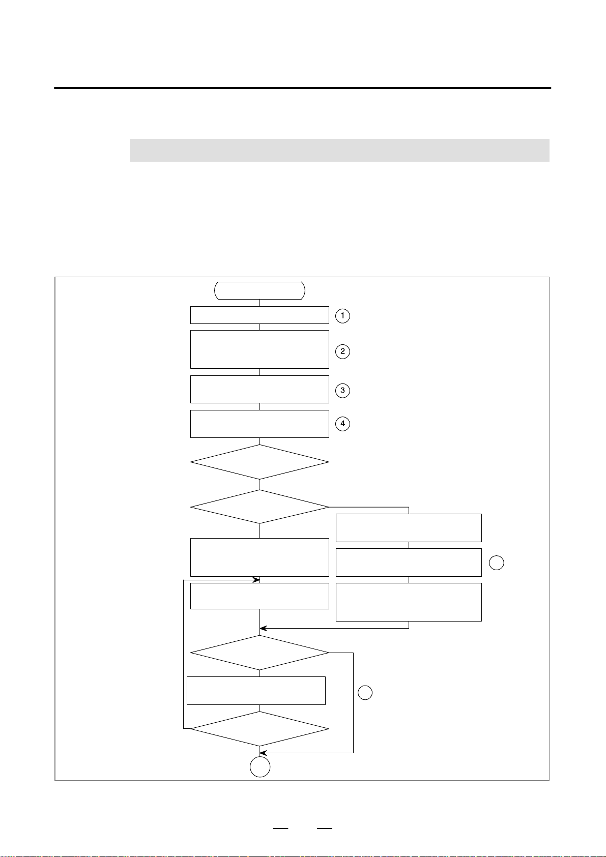
B–61863E/15
1
1. SEQUENCE PROGRAM
PMC SEQUENCE PROGRAM
CREATING PROCEDURE
SEQUENCE PROGRAM CREATING PROCEDURE
The procedure for creating the sequence program when the CNC machine
tool is controlled by use of the PMC is shown in Fig. 1.
Proceed according to the flow shown in Fig. 1.
The procedure is briefly explained below.
Start of control system
development
Decide the control object (machine, CNC)
Decide the specifications of control
operations
D Calculate the number of DI/DO points
D Estimate the control scale
Create the interface specifications
DI/DO terminal allocation
Create the ladder diagram
Create the addrss table
Entry method of the
sequence program
Key-in
Specification of the
programmer
NC
Store the sequence program into the PMC
RAM board by using the keys of the
CRT/MDI
If necessary correct with the keys of the
CRT/MDI
Is there a simulator?
Yes
Debug the sequence program with the
simulator
Offline programmer
Enter the sequence program with the offline
programmer key
In necessary correct with the offline
programmer key
When the debugging connect the offline
programmer to CNC and transfer the
sequence program to Debugging RAM
No
6
5
Yes
Should the program be
corrected?
No
A
Fig. 1 Sequence program creating procedure (1/2)
3
Page 38
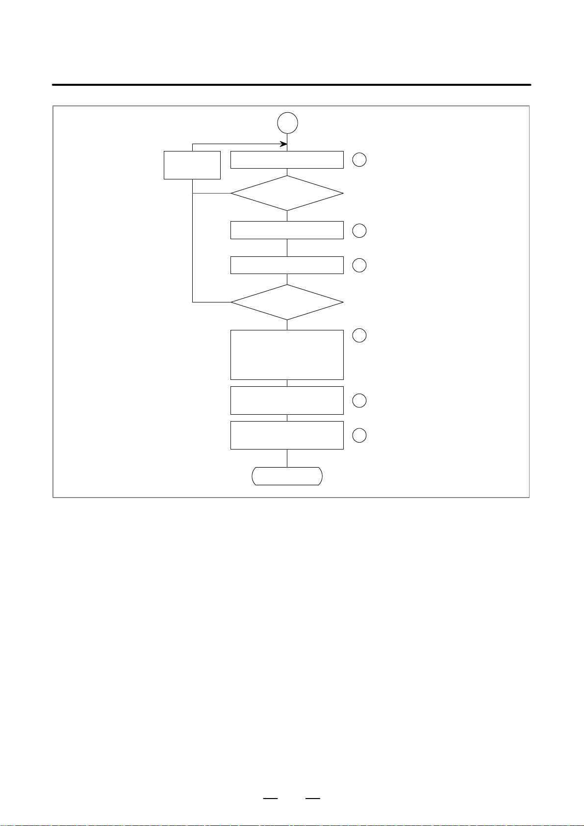
1. SEQUENCE PROGRAM
CREATING PROCEDURE
PMC SEQUENCE PROGRAM
A
B–61863E/15
Correct with
the keys of the
CRT/MDI
Perform system operation
Debugging RAM
Yes
Yes
Should the program
be corrected?
Write into the ROM using the
ROM writer
Perform system operation
Should the program
be corrected?
No
Store the sequence program:
(1) Store in the disk of the offline
programmer
(2) Store in ROM
Output the ladder diagram of the
sequence program to the printer
Make sure that the maintenance
drawing is attached to the machine
7
8
9
10
11
12
End
Fig. 1 Sequence program creating procedure (2/2)
4
Page 39
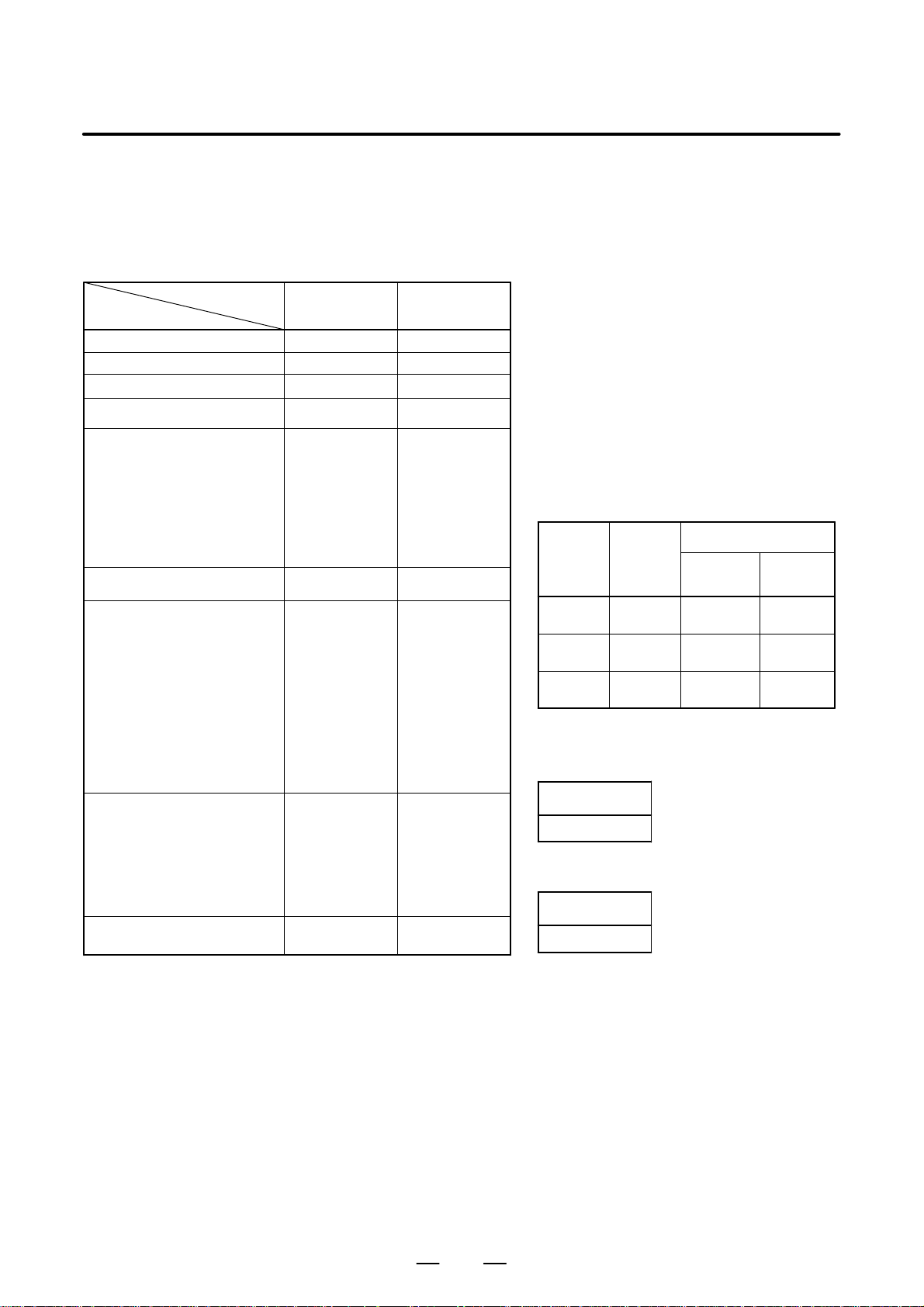
B–61863E/15
PMC SEQUENCE PROGRAM
1. SEQUENCE PROGRAM
CREATING PROCEDURE
1.1
Table 1.1 shows the specification of PMCs.
Note that the program size, processing speed, available function
SPECIFICATION OF PMCs
Specification
of PMC
Program method language Ladder Ladder
Number of ladder level 2 2
1st level execution period 8 ms 8 ms
Mean processing time of
basic command
Program capacity
D Ladder (step) (Note 1,3)
D Symbol, Comment (Note 2,3)
D Message (Note 3)
D Language only
Command Basic command
Internal relay (R)
Message request (A)
Keepmemory
D Variable timer (T)
D Counter (C)
D Keep relay (K)
D Data table (D)
Subprogram (P)
Label (L)
Fixed timer
I/O
D I/O Link (Note 4) (I)
(Master) (O)
D I/O Link (Note 7) (I)
(Slave) (O)
D I/O card (I)
(O)
Sequence program
T ype of PMC
Approx. 3, 000
1 to 128KB
0.1 to 64KB
Function command
1100 byte
25 byte
80 byte
80 byte
20 byte
1860 byte
Timer No. 100
devices specified
1024 points max.
1024 points max.
64 points max.
64 points max.
32 points max.
24 points max.
(Note 5)
commands, internal addresses, and nonvolatile memory addresses of
some PMCs are different from those of other PMCs.
T able 1.1 PMC specifications (1)
PMC-PA1 PMC-PA3
4. 5
(µs/ step)
–
12 kinds
47 kinds
–
–
SRAM SRAM
0. 15
*
(µs/ step)
Approx. 5, 000
Approx. 12,000
(Only for Power
Mate D/H)
1 to 128KB
0.1 to 64KB
–
14 kinds
64 kinds
1118 byte
25 byte
80 byte
80 byte
20 byte
1860 byte
512 programs
9999 labels
Timer No. 100
devices specified
1024 points max.
1024 points max.
64 points max.
64 points max.
32 points max.
24 points max.
D Power Mate D Data size of each modules
MEMORY-
MODULE
A 256KB 62KB
B 512KB 128KB
C 768KB 128KB
It is impossible that make the data more than the total
capacity of each modules.
Total
capacity
Program size
One–Path
control
Two–Path
control
24KB
64KB
128KB
D Power Mate F
Program size
64KB
D Power Mate H
Program size
128KB
5
Page 40

1. SEQUENCE PROGRAM
CREATING PROCEDURE
PMC SEQUENCE PROGRAM
B–61863E/15
NOTE
1 This is the number of ladder steps for the program only with basic instructions. The use of
functional instructions may vary the number of ladder steps.
2 The size of a symbol and that of a comment are fixed to 1KB.
The size of a message is fixed to 0.1KB.
The maximum size of a symbol and that of a comment are 64KB each.
3 These have no limit of size for each. However , the total size of sequence program (the sum total
of ladder, symbols/comments, messages, etc.) never exceed the storage size of sequence
program. The size of them influences the capacity of others.
4 I/O Link Master function is not available in the Power Mate–MODEL F.
5 FLASH ROM is used in the Power Mate–MODEL H.
6 As values indicated with an asterisk (*) in the table, former versions of the programming manual
and catalogs have listed the mean processing time of basic commands, but this manual lists
the execution time for one step. The actual ladder program execution performance (speed) of
each PMC has not been changed.
7 Up to 256/256 points of Input/Output points are available or I/O Link (Slave) in the Power
Mate–MODEL D/H.
6
Page 41
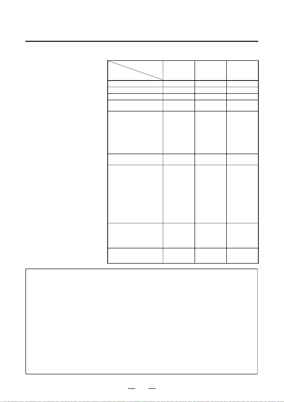
B–61863E/15
1. SEQUENCE PROGRAM
PMC SEQUENCE PROGRAM
T able 1.1 PMC specifications (2)
T ype of PMC
Specification
PMC–SA1 PMC–SA2 PMC–SA3
of PMC
Program method language Ladder Ladder Ladder
Number of ladder level 2 2 2
1st level execution period 8 ms 8 ms 8 ms
Mean processing time of basic
command
Program capacity
D Ladder (step) (Note 1,3)
D Symbol, Comment
(Note 2,3)
D Message (Note 3)
D Language only
Command Basic command
Function command
Internal relay (R)
Message request (A)
Keepmemory
D Variable timer (T)
D Counter (C)
D Keep relay (K)
D Data table (D)
Subprogram (P)
Label (L)
Fixed timer
I/O
D I/O link (I)
(O)
D I/O card (I)
(O)
Sequence program EPROM
5.0
(µs/ step)
Approx. 3, 000
Approx. 5, 000
1 to 128KB
0. 1 to 64KB
–
12 kinds
49 kinds
1100 byte
25 byte
80 byte
80 byte
20 byte
1860 byte
–
–
Timer No. 100
devices specified
1024 points max.
1024 points max.
156 points max.
120 points max.
1Mbit×1 (128KB)
(Note 4)
CREATING PROCEDURE
1.5
(µs/ step)
Approx. 3, 000
Approx. 5, 000
Approx. 8, 000
Approx.12, 000
1 to 128KB
0. 1 to 64KB
–
12 kinds
48 kinds
1118 byte
25 byte
80 byte
80 byte
20 byte
1860 byte
–
–
Timer No. 100
devices specified
1024 points max.
1024 points max.
156 points max.
120 points max.
EPROM
1Mbit×1 (128KB)
0. 15
*
(µs/ step)
Approx. 3, 000
Approx. 5, 000
Approx. 8, 000
Approx.12, 000
1 to 128KB
0. 1 to 64KB
–
14 kinds
66 kinds
1118 byte
25 byte
80 byte
80 byte
20 byte
1860 byte
512 programs
9999 labels
Timer No. 100
devices specified
1024 points max.
1024 points max.
156 points max.
120 points max.
EPROM
1Mbit×1 (128KB)
(Note 4)
NOTE
1 This is the number of ladder steps for the program only with basic instructions. The use of
functional instructions may vary the number of ladder steps.
2 The size of a symbol and that of a comment are fixed to 32KB.
The size of a message is fixed to 2.1KB.
The maximum size of a symbol and that of a comment are 64KB each.
3 These have no limit of size for each. However , the total size of sequence program (the sum total
of ladder, symbols/comments, messages, etc.) never exceed the storage size of sequence
program. The size of them influences the capacity of others.
4 FLASH ROM is used in the FANUC Series 20.
5 As values indicated with an asterisk (*) in the table, former versions of the programming manual
and catalogs have listed the mean processing time of basic commands, but this manual lists
the execution time for one step. The actual ladder program execution performance (speed) of
each PMC has not been changed.
6 Application PMC for FANUC Series 16–MODEL A loader control function is PMC–SA1.
7
Page 42
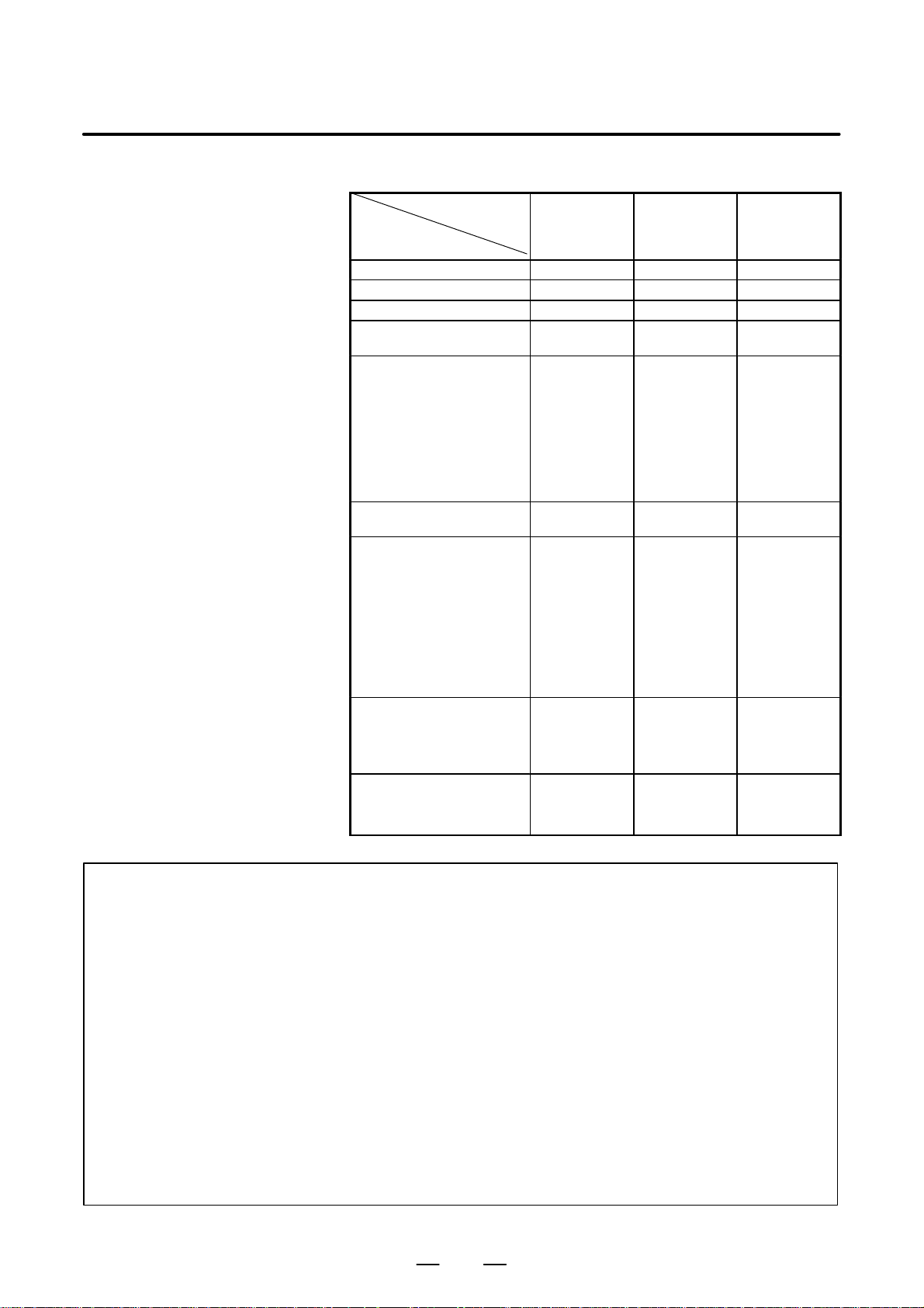
1. SEQUENCE PROGRAM
CREATING PROCEDURE
PMC SEQUENCE PROGRAM
B–61863E/15
T able 1.1 PMC specifications (3)
T ype of PMC
Specification
PMC–SB1 PMC–SB2 PMC–SB3
of PMC
Program method language Ladder Ladder Ladder
Number of ladder level 2 2 2
1st level excution period 8 ms 8 ms 8 ms
Mean processing time of basic
command
Program capacity
D Ladder (step) (Note 1,3,4)
D Symbol, Comment
(Note 2,4)
D Message (Note 4)
D Language only
Command Basic command
Function command
Internal relay (R)
Message request (A)
Keepmemory
D Variable timer (T)
D Counter (C)
D Keep relay (K)
D Data table(D) (D)
Subprogram (P)
Label (L)
Fixed timer
I/O
D I/O link (I)
(O)
D I/O card (I)
(Note 5) (O)
Sequence program EPROM
1.0
(µs/ step)
Approx. 5, 000
Approx. 8, 000
Approx.12, 000
Approx.16, 000
1 to 128KB
0.1 to 64KB
–
12 kinds
49 kinds
1100 byte
25 byte
80 byte
80 byte
20 byte
1860 byte
–
–
Timer No. 100
devices specified
1024 points max.
1024 points max.
156 points max.
120 points max.
1Mbit×1 (128KB)
1.0
(µs/ step)
Approx. 5, 000
Approx. 8, 000
Approx.12, 000
Approx.16, 000
Approx.24, 000
1 to 128KB
0.1 to 64KB
–
12 kinds
49 kinds
1118 byte
25 byte
80 byte
80 byte
20 byte
1860 byte
–
–
Timer No. 100
devices specified
1024 points max.
1024 points max.
156 points max.
120 points max.
EPROM
1Mbit×1 (128KB)
ROM MODULE
256KB (Note 3)
0. 15
*
(µs/ step)
Approx. 5, 000
Approx. 8, 000
Approx.12, 000
Approx.16, 000
Approx.24, 000
1 to 128KB
0.1 to 64KB
–
14 kinds
68 kinds
1618 byte
25 byte
80 byte
80 byte
20 byte
3000 byte
512 programs
9999 labels
Timer No. 100
devices specified
1024 points max.
1024 points max.
156 points max.
120 points max.
EPROM
1Mbit×1 (128KB)
ROM MODULE
256KB (Note 3)
NOTE
1 This is the number of ladder steps for the program only with basic instructions. The use of
functional instructions may vary the number of ladder steps.
2 The size of a symbol and that of a comment are fixed to 32KB.
The size of a message is fixed to 2.1KB.
The maximum size of a symbol and that of a comment are 64KB each.
3 When the number of steps of the PMC-SB2, SB3 ladder program is approx. 24,000, the
capacity of the ROM module must be 256KB.
4 These have no limit of size for each. However , the total size of sequence program (the sum total
of ladder, symbols/comments, messages, etc.) never exceed the storage size of sequence
program. The size of them influences the capacity of others.
5 As values indicated with an asterisk (*) in the table, former versions of the programming manual
and catalogs have listed the mean processing time of basic commands, but this manual lists
the execution time for one step. The actual ladder program execution performance (speed) of
each PMC has not been changed.
8
Page 43

B–61863E/15
PMC SEQUENCE PROGRAM
T able 1.1 PMC specifications (4)
T ype of PMC
Specification
of PMC
1. SEQUENCE PROGRAM
CREATING PROCEDURE
PMC–SC PMC–SC3 PMC–NB
Program method language Ladder
Number of ladder level 3 3 3
1st level execution period 8 ms 8 ms 8 ms
Mean processing time of basic
command
Program capacity
D Ladder (step) (Note 1,3)
D Symbol, Comment
(Note 2,3)
D Message (Note 3)
D Language only
Command Basic command
Function command
Internal relay (R)
Message request (A)
Keepmemor
D Variable timer (T)
D Counter (C)
D Keep relay (K)
D Data table (D)
Subprogram (P)
Label (L)
Fixed timer
C-language
0.15
(µs/ step)
Approx. 16,000
Approx. 24,000
1 to 128KB
0.1 to 64KB
896KB max.
12 kinds
51 kinds
1600 byte
25 byte
80 byte
80 byte
20 byte
3000 byte
–
–
Timer No. 100
devices specified
Ladder
C-language
0.15
(µs/ step)
Approx. 16,000
Approx. 24,000
1 to 128KB
0.1 to 64KB
896KB max.
14 kinds
68 kinds
1618 byte
25 byte
80 byte
80 byte
20 byte
3000 byte
512 programs
9999 labels
Timer No. 100
devices specified
Ladder
C-language
0.15
(µs/ step)
Approx. 8,000
Approx. 16,000
(Note 4)
Approx. 24,000
(Note 4)
1 to 128KB
0.1 to 64KB
896KB max.
14 kinds
68 kinds
1618 byte
25 byte
80 byte
80 byte
20 byte
3000 byte
512 programs
9999 labels
Timer No. 100
devices specified
I/O
D I/O link (I)
D I/O card (I)
Sequence program ROM MODULE
(O)
(O)
1024 points max.
1024 points max.
156 points max.
120 points max.
128KB (16,000
steps option)
256KB (24,000
steps option)
512KB (24,000
steps option)
1MB (24,000
steps option)
9
1024 points max.
1024 points max.
156 points max.
120 points max.
ROM MODULE
128KB (16,000
steps option)
256KB (24,000
steps option)
512KB (24,000
steps option)
1MB (24,000
steps option)
1024 points max.
1024 points max.
–
–
Flash ROM
64KB
(8,000 steps)
128KB
(16,000 steps)
256KB
(24,000 steps)
512KB
(24,000 steps)
1MB
(24,000 steps)
Page 44

1. SEQUENCE PROGRAM
CREATING PROCEDURE
PMC SEQUENCE PROGRAM
B–61863E/15
NOTE
1 This is the number of ladder steps for the program only with
basic instructions. The use of functional instructions may
vary the number of ladder steps.
2 The size of a symbol and that of a comment of PMC-SC/SC3
are fixed 32KB. The size of message of PMC-SC/SC3 is
fixed 2.1KB. The size of a symbol and that of a comment
of PMC-NB are fixed 28KB. The size of message of
PMC-NB is fixed 2.1KB. The maximum size of a symbol and
that of a comment are 64KB each.
3 These have no limit of size for each. However, the total size
of sequence program (the sum total of ladder,
symbols/comments, messages, etc.) never exceed the
storage size of sequence program. The size of them
influences the capacity of others.
4 When the number of steps of the PMC-NB ladder program
is not less than 8,000, the OPTION DRAM is required.
(A02B-0162-J151, J152)
10
Page 45

B–61863E/15
PMC SEQUENCE PROGRAM
T able 1.1 PMC specifications (5)
1. SEQUENCE PROGRAM
CREATING PROCEDURE
Series 18–
MODEL B
Model
Series 16–MODEL B/Series 18–MODEL B
PMC–SB3 PMC–SC3 PMC–SB4 PMC–SC4 PMC–SA1
Programming method
language
Number of ladder level 2 3 2 3 2
Level-1 Cycle Time 8 ms 8 ms 8 ms 8 ms 8 ms
Basic Instruction Execution Time 0.1
Program capacity
D Ladder (step) (Note 1,3)
D Symbol/Comment (Note 2,3)
D Message (Note 3)
D Language only
Instruction (Basic)
(Functional)
Internal relay (R)
Message request (A)
Non-volatile
D Var. Timer (T)
D Counter (C)
D Keep relay (K)
D Data table (D)
Subprogram (P)
Label (L)
Fixed timer
Input/output
D I/O link (I) Max.
(O) Max.
D I/O card (I) Max.
(Note 4) (O) Max.
Sequence program
storage media
Ladder
*
(µs/ step)
Approx. 5, 000
Approx. 8, 000
Approx.12, 000
Approx.16, 000
Approx.24, 000
1 to 128KB
0.1 to 64KB
–
14 kinds
67 kinds
1618 byte
25 byte
80 byte
80 byte
20 byte
3000 byte
512 programs
9999 labels
Timer No. 100
devices specified
1024 points max.
1024 points max.
312 points max.
240 points max.
Flash ROM
128KB (16,000
steps option or
less)
256KB (24,000
steps option)
Ladder
C–language
0.1
(µs/ step)
Approx.16, 000
Approx.24, 000
1 to 128KB
0.1 to 64KB
max. 896KB
14 kinds
69 kinds
1618 byte
25 byte
80 byte
80 byte
20 byte
3000 byte
512 programs
9999 labels
Timer No. 100
devices specified
1024 points max.
1024 points max.
312 points max.
240 points max.
Flash ROM
128KB (16,000
steps option)
256KB (24,000
steps option)
512KB (24,000
steps option)
1MB (24,000
steps option)
Ladder
Step sequence
0.1
*
(µs/ step)
Approx. 5, 000
Approx. 8, 000
Approx.12, 000
Approx.16, 000
Approx.24, 000
1 to 128KB
0.1 to 64KB
–
14 kinds
67 kinds
3200 byte
125 byte
300 byte
200 byte
50 byte
8000 byte
2000 programs
9999 labels
Timer No. 100
devices specified
1024 points max.
1024 points max.
312 points max.
240 points max.
Flash ROM
128KB (16,000
steps option or
less)
256KB (24,000
steps option)
Ladder
C–language
Step sequece
0.1
(µs/ step)
Approx.16, 000
Approx.24, 000
1 to 128KB
0.1 to 64KB
max. 896KB
14 kinds
69 kinds
3200 byte
125 byte
300 byte
200 byte
50 byte
8000 byte
2000 programs
9999 labels
Timer No. 100
devices specified
1024 points max.
1024 points max.
312 points max.
240 points max.
Flash ROM
128KB (16,000
steps option)
256KB (24,000
steps option)
512KB (24,000
steps option)
1MB (24,000
steps option)
Ladder
5.0
(µs/ step)
Approx. 3, 000
Approx. 5, 000
1 to 128KB
0.1 to 64KB
–
12 kinds
49 kinds
1100 byte
25 byte
80 byte
80 byte
20 byte
1860 byte
–
–
Timer No. 100
devices specified
1024 points max.
1024 points max.
312 points max.
240 points max.
Flash ROM
128KB
11
Page 46

1. SEQUENCE PROGRAM
CREATING PROCEDURE
PMC SEQUENCE PROGRAM
B–61863E/15
NOTE
1 This is the number of ladder steps for the program only with basic instructions. The use of
functional instructions may vary the number of ladder steps.
2 The size of a symbol and that of a comment are fixed 32KB. The size of message is fixed 2.1KB.
The maximum size of a symbol and that of a comment are 64KB each.
3 These have no limit of size for each. However , the total size of sequence program (the sum total
of ladder, symbols/comments, messages, etc.) never exceed the storage size of sequence
program. The size of them influences the capacity of others.
4 That is the maximum number when 2 I/O cards (with 156 inputs/120 outputs) are used.
5 As values indicated with an asterisk (*) in the table, former versions of the programming manual
and catalogs have listed the mean processing time of basic commands, but this manual lists
the execution time for one step. The actual ladder program execution performance (speed) of
each PMC has not been changed.
6 Application PMC for FANUC Series 16–MODEL B loader control function is PMC–SA1.
12
Page 47

B–61863E/15
PMC SEQUENCE PROGRAM
T able 1.1 PMC specifications (6)
1. SEQUENCE PROGRAM
CREATING PROCEDURE
Model
Series 16–MODEL C/Series 18–MODEL C
PMC–SB5 PMC–SC3 PMC–SB6 PMC–SC4
Programming method
language
Number of ladder level 2 3 2 3
Level-1 Cycle Time 8 ms 8 ms 8 ms 8 ms
Basic Instruction Execution Time 0.1
Program capacity
D Ladder (step) (Note 1,3)
D Symbol/Comment (Note 2,3)
D Message (Note 3)
D Language only
Instruction (Basic)
(Functional)
Ladder
(µs/ step)
Approx. 3, 000
Approx. 5, 000
Approx. 8, 000
Approx.12, 000
Approx.16, 000
Approx.24, 000
1 to 128KB
0.1 to 64KB
–
14 kinds
67 kinds
Ladder
C–language
0.1
(µs/ step)
Approx.16, 000
Approx.24, 000
1 to 128KB
0.1 to 64KB
max. 896KB
14 kinds
69 kinds
Ladder
Step sequence
0.1
(µs/ step)
Approx. 3, 000
Approx. 5, 000
Approx. 8, 000
Approx.12, 000
Approx.16, 000
Approx.24, 000
Approx.32, 000
1 to 128KB
0.1 to 64KB
–
14 kinds
67 kinds
Ladder
C–language
Step sequece
0.1
(µs/ step)
Approx.16, 000
Approx.24, 000
Approx.32, 000
1 to 128KB
0.1 to 64KB
max. 896KB
14 kinds
69 kinds
Internal relay (R)
Message request (A)
Non-volatile
D Var. Timer (T)
D Counter (C)
D Keep relay (K)
D Data table (D)
Subprogram (P)
Label (L)
Fixed timer
Input/output
D I/O link (I) Max.
(O) Max.
D I/O card (I) Max.
(Note 4) (O) Max.
Sequence program
storage media
1618 byte
25 byte
80 byte
80 byte
20 byte
3000 byte
512 programs
9999 labels
Timer No. 100
devices specified
1024 points max.
1024 points max.
312 points max.
240 points max.
Flash ROM
128KB (16,000
steps option or less)
256KB (24,000 steps
option)
1618 byte
25 byte
80 byte
80 byte
20 byte
3000 byte
512 programs
9999 labels
Timer No. 100
devices specified
1024 points max.
1024 points max.
312 points max.
240 points max.
Flash ROM
128KB (16,000 steps
option)
256KB (24,000 steps
option)
512KB (24,000 steps
option)
1MB (24,000 steps
option)
3200 byte
125 byte
300 byte
200 byte
50 byte
8000 byte
2000 programs
9999 labels
Timer No. 100
devices specified
1024 points max.
1024 points max.
312 points max.
240 points max.
Flash ROM
128KB (16,000
steps option or less)
256KB (24,000 steps
option)
3200 byte
125 byte
300 byte
200 byte
50 byte
8000 byte
2000 programs
9999 labels
Timer No. 100
devices specified
1024 points max.
1024 points max.
312 points max.
240 points max.
Flash ROM
128KB (16,000 steps
option)
256KB (24,000 steps
option)
512KB (24,000 steps
option)
1MB (24,000 steps
option)
13
Page 48

1. SEQUENCE PROGRAM
CREATING PROCEDURE
PMC SEQUENCE PROGRAM
B–61863E/15
NOTE
1 This is the number of ladder steps for the program only with basic instructions. The use of
functional instructions may vary the number of ladder steps.
2 The size of a symbol and that of a comment are fixed 32KB. The size of message is fixed 2.1KB.
The maximum size of a symbol and that of a comment are 64KB each.
3 These have no limit of size for each. However , the total size of sequence program (the sum total
of ladder, symbols/comments, messages, etc.) never exceed the storage size of sequence
program. The size of them influences the capacity of others.
4 That is the maximum number when 2 I/O cards (with 156 inputs/120 outputs) are used.
5 Application PMC for FANUC Series 16–MODEL C loader control function is PMC–SA1.
14
Page 49

B–61863E/15
Model
1. SEQUENCE PROGRAM
PMC SEQUENCE PROGRAM
T able 1.1 PMC specifications (7)
Model
Programming method
language
Number of ladder level 2 2
1st level excution period 8 ms 8 ms
Mean processing time of basic command 5.0
Program capacity
D Ladder (step) (Note 1,4)
D Symbol/Comment (Note 2,4)
(Note 4)
D Message
D Language only
Command Basic command
Functioncommand
Internal relay (R)
Message request (A)
Keepmemory
D Variable timer (T)
D Counter (C)
D Keep relay (K)
D Data table (D)
Subprogram (P)
Label (L)
Fixed timer
I/O
D I/O link (I)
(O)
D I/O card (I)
(O)
Sequence program Flash ROM
CREATING PROCEDURE
Series 21–MODEL B/
Series 210–MODEL B
PMC–SA1 PMC–SA3
Ladder Ladder
0.15
(µs/ step)
Approx. 3, 000
Approx. 5, 000
1 to 128KB
0.1 to 64KB
–
12 kinds
49 kinds
1100 byte
25 byte
80 byte
80 byte
20 byte
1860 byte
–
–
Timer No. 100
devices specified
1024 points max.
1024 points max.
96 points max.
72 points max.
(Note 5)
128KB (Note 3)
*
(µs/ step)
Approx. 3, 000
Approx. 5, 000
Approx. 8, 000
Approx.12, 000
Approx.16, 000
1 to 128KB
0.1 to 64KB
–
14 kinds
66 kinds
1118 byte
25 byte
80 byte
80 byte
20 byte
1860 byte
512 programs
9999 labels
Timer No. 100
devices specified
1024 points max.
1024 points max.
96 points max.
72 points max.
(Note 5)
Flash ROM
128KB (Note 5)
15
Page 50

1. SEQUENCE PROGRAM
CREATING PROCEDURE
PMC SEQUENCE PROGRAM
B–61863E/15
NOTE
1 This is the number of ladder steps for the program only with
basic instructions. The use of functional instructions may
vary the number of ladder steps.
2 The size of a symbol and that of a comment are fixed 32KB.
The size of message is fixed 2.1KB. The maximum size of
a symbol and that of a comment are 64KB each.
3 When extended memory is not specified in the 4082 series
(ordering drawing No.: A02B–0210–H020 or
A02B–0210–H022), the program capacity is 64KB.
4 These have no limit of size for each. However, the total size
of sequence program (the sum total of ladder,
symbols/comments, messages, etc.) never exceed the
storage size of sequence program. The size of them
influences the capacity of others.
5 Output points of I/O card in 4082 or 4084 series are following;
PMC–SA1 : 64points, PMC–SA3 : 64points
6 As values indicated with an asterisk (*) in the table, former
versions of the programming manual and brochure have
listed the mean processing time of basic commands, but this
manual lists the execution time for one step. The actual
ladder program execution performance (speed) of each
PMC has not been changed.
7 Application PMC for FANUC Series 21–B loader control
function is PMC–SA1.
16
Page 51

B–61863E/15
PMC SEQUENCE PROGRAM
T able 1.1 PMC specifications (8)
FANUC Series 16i/160i/18i/180i
1. SEQUENCE PROGRAM
CREATING PROCEDURE
Model PMC–SA5
PMC–SB5 PMC–SB6
(Loader control)
Programming method Ladder Ladder Ladder step sequence
Number of ladder levels 2 2 2
First–level execution period 8 ms 8 ms 8 ms
Basic instruction processing time 5.0 µ sec/step 0.085 µ sec/step 0.085 µ sec/step
Program capacity
D Ladder (step) (Note 1,2)
D Symbol & Comment (Note 2)
D Message (Note 2)
Instruction (Basic instruction)
(Functional instruction)
Internal relay (R)
Message request (A)
Nonvolatile memory
D Variable timer (T)
D Counter (C)
D Keep replay (K)
D Data table (D)
Subprogram (P)
Label (L)
Fixed timer
(Timernumber specification)
About 3,000
About 5,000
About 8,000
About 12,000
1KB to 128KB
0.1KB to 64KB
12
48
1100 bytes
25 bytes (200 points)
80 bytes (40 each)
80 bytes (20 each)
20 bytes
1,860 bytes
100 each
About 3,000
About 5,000
About 8,000
About 12,000
About 16,000
About 24,000
1KB to 128KB
0.1KB to 64KB
25 bytes (200 points)
80 bytes (40 each)
80 bytes (20 each)
–
–
14
66
1618 bytes
20 bytes
3,000 bytes
512 each
9999 each
100 each
About 3,000
About 5,000
About 8,000
About 12,000
About 16,000
About 24,000
About 32,000
About 40,000
1KB to 128KB
0.1KB to 64KB
14
67
3200 bytes
125 bytes (1000 points)
300 bytes (150 each)
200 bytes (50 each)
50 bytes
8,000 bytes
2000 each
9999 each
100 each
I/O
D I/O link (Input)
(Note 4)
(Output)
Sequence program storage media Flash ROM
1024 points maximum
1024 points maximum
128KB
1024 points maximum
1024 points maximum
Flash ROM
128KB (16,000
steps option or less)
256KB (24,000
steps option or less)
2048 points maximum
(Note 5)
2048 points maximum
(Note 5)
Flash ROM
128KB (16,000
steps option or less)
256KB (24,000
steps option)
384KB (32,000/40,000
steps option)
17
Page 52

1. SEQUENCE PROGRAM
CREATING PROCEDURE
PMC SEQUENCE PROGRAM
B–61863E/15
NOTE
1 This is the number of ladder steps for the program only with basic instructions. The use of
functional instructions may vary the number of ladder steps.
2 These have no limit of size for each. However , the total size of sequence program (the sum total
of ladder, symbols/comments, messages, etc.) never exceed the storage size of sequence
program. The size of them influences the capacity of others.
3 The PMC–SA1 can be used with the loader control function of the FANUC Series
16i/18i/21i/160i/180i/210i–A.
4 For I/O of the FANUC Series 16i/18i/21i/160i/180i/210i–A, only the I/O link is used.
5 1024 points maximum (channel 1)+1024 points maximum (channel 2)= 2048 points maximum.
You can use the I/O Link channel 2 only when CNC hardware support the I/O Link 2–channel
and optional I/O Link expansion is provided with CNC.
18
Page 53

1. SEQUENCE PROGRAM
B–61863E/15
Model
Programming method Ladder Ladder Ladder
Number of ladder levels 2 2 2 2
First–level execution period 8 ms 8 ms 8 ms 8 ms
Basic instruction
processing time
Program capacity
D Ladder (step)
(Note 1,2)
D Symbol & Comment
(Note 2)
D Message (Note 2)
Instruction
(Basic instruction)
(Functional instruction)
Internal relay (R)
Message request (A)
Nonvolatile memory
D Variable timer (T)
D Counter (C)
D Keep replay (K)
D Data table (D)
Subprogram (P)
Label (L)
Fixed timer
(Timernumber
specification)
I/O
D I/O link (Input)
(Note 4)
(Output)
Sequence program storage
media
PMC–SA1 PMC–SA5
5.0 µ sec/ step 5.0 µ sec/ step 0.085 µ sec/ step 0.085 µ sec/ step
About 3,000
About 5,000
1KB to 128KB
0.1KB to 64KB
12
48
1100 bytes
25 bytes (200 points)
80 bytes (40 each)
80 bytes (20 each)
20 bytes
1860 bytes
–
–
1024 points maximum
1024 points maximum
Flash ROM
128KB
PMC SEQUENCE PROGRAM
T able 1.1 PMC specifications (9)
FANUC Series 21i/210i
(Loader control)
About 3,000
About 5,000
About 8,000
About 12,000
1KB to 128KB
0.1KB to 64KB
12
48
1100 bytes
25 bytes (200 points)
80 bytes (40 each)
80 bytes (20 each)
20 bytes
1,860 bytes
–
–
100 each
1024 points maximum
1024 points maximum
Flash ROM
128KB
100 each
CREATING PROCEDURE
PMC–SA5 PMC–SB6
About 3,000
About 5,000
About 8,000
About 12,000
About 16,000
1KB to 128KB
0.1KB to 64KB
14
66
1118 bytes
25 bytes (200 points)
80 bytes (40 each)
80 bytes (20 each)
20 bytes
1860 bytes
512 each
9999 each
100 each
1024 points maximum
1024 points maximum
Flash ROM
128KB
About 3,000
About 5,000
About 8,000
About 12,000
About 16,000
About 24,000
About 32,000
About 40,000
1KB to 128KB
0.1KB to 64KB
125 bytes (1000 points)
300 bytes (150 each)
2048 points maximum
(Note 5)
2048 points maximum
(Note 5)
Flash ROM
128KB (16,000
steps option or less)
256KB (24,000
steps option)
384KB (32,000/40,000
steps option)
Ladder
Step sequence
14
67
200 bytes (50 each)
3200 bytes
50 bytes
8,000 bytes
2000 each
9999 each
100 each
19
Page 54

1. SEQUENCE PROGRAM
CREATING PROCEDURE
PMC SEQUENCE PROGRAM
B–61863E/15
NOTE
1 This is the number of ladder steps for the program only with basic instructions. The use of
functional instructions may vary the number of ladder steps.
2 These have no limit of size for each. However , the total size of sequence program (the sum total
of ladder, symbols/comments, messages, etc.) never exceed the storage size of sequence
program. The size of them influences the capacity of others.
3 The PMC–SA1 can be used with the loader control function of the FANUC Series
16i/18i/21i/160i/180i/210i–A.
4 For I/O of the FANUC Series 16i/18i/21i/160i/180i/210i–A, only the I/O link is used.
5 1024 points maximum (channel 1)+1024 points maximum (channel 2)= 2048 points maximum.
You can use the I/O Link channel 2 only when CNC hardware support the I/O Link 2–channel
and optional I/O Link expansion is provided with CNC.
20
Page 55

B–61863E/15
1. SEQUENCE PROGRAM
PMC SEQUENCE PROGRAM
T able 1.1 PMC specifications (10)
FUNAC Power Mate i–MODEL D/H
Model
Programming method Ladder Ladder step sequence
Number of ladder levels 2 2
Level–1 cycle time 8 ms 8 ms
Basic instruction execution time 0.085
Program capacity
D Ladder (step) (Note 1,2)
D Symbol/Comment (Note 2)
D Message (Note 2)
Instruction (Basic)
(Functional)
Internal relay (R)
Message request (A)
Non–volatile
D Var.timer (T)
D Counter (C)
D Keep replay (K)
D Data table (D)
Subprogram (P)
Label (L)
Fixed timer
Input/Output
D I/O Link (I) Max.
(master) (O) Max.
D I/O Link (I) Max.
(slave) (O) Max.
D Built–in I/O (I) Max.
(O) Max.
Sequence program storage media Flash ROM
PMC–SB5 PMC–SB6
(µ sec/step)
Approx. 5,000
Approx. 12,000
Approx. 16,000
Approx. 24,000
1 to 128KB
0.1 to 64KB
25 bytes (200 points)
80 bytes (40 points)
80 bytes (20 points)
Timer No.100
devices specified
1024 points max.
1024 points max.
256 points max.
256 points max.
32 points max.
24 points max.
128KB (16,000
steps option or less)
256KB (24,000
steps option)
CREATING PROCEDURE
14 kinds
67 kinds
1618 bytes
20 bytes
3000 bytes
512 programs
9999 labels
0.085
(µ sec/step)
Approx. 5,000
Approx. 12,000
Approx. 16,000
Approx. 24,000
Approx. 32,000
Approx. 40,000
1 to 128KB
0.1 to 64KB
14 kinds
67 kinds
3200 bytes
125 bytes (200 points)
300 bytes (150 points)
200 bytes (50 points)
50 bytes
8000 bytes
2000 programs
9999 labels
Timer No.100
devices specified
1024 points max.
1024 points max.
256 points max.
256 points max.
32 points max.
24 points max.
Flash ROM
128KB (16,000
steps option or less)
256KB (24,000
steps option)
384KB (32,000
steps option)
NOTE
1 This is the number of ladder steps for the program only with
basic instructions. The use of functional instructions may
vary the number of ladder steps.
2 These have no limit of size for each. However, the total size
of sequence program (the sum total of ladder, symbols/
comments, messages, etc.) never exceed the storage size
of sequence program. The size of them influences the
capacity of others.
21
Page 56

1. SEQUENCE PROGRAM
CREATING PROCEDURE
PMC SEQUENCE PROGRAM
B–61863E/15
T able 1.1 PMC specifications (11)
Series 15–MODEL B
Model
PMC–NB
PMC–NB2
(4048 Series)
Programming method language Ladder
Number of ladder level 3 3
Level–1 Cycle Time 8 ms 8 ms
Basic instruction
Execution Time
Program capacity
S Ladder(step) (Note 1,2)
S Symbol/Comment
(Note 2)
S Message (Note 2)
S Language only
Instruction (Basic)
(Function)
Internal relay (R)
Message request (A)
Non–volatile
S Var.Timer (T)
S Counter (C)
S Keep relay (K)
S Data table (D)
Subprogram (P)
Label (L)
Fixed timer
Input/output
S I/O link (I)
(O)
S I/O card (I)
(O)
Sequence program
storage media
C–language
0.1
(µs/step)
Approx. 8,000
Approx.16,000
Approx.24,000
1 to 128KB
0.1 to 64KB
max. 896KB
14 kinds
69 kinds
1618 bytes
25 bytes
80 bytes
80 bytes
20 bytes
3000 bytes
512 programs
9999 labels
Max 100 timers
specified by
timer No.
max 1024 points.
max 1024 points.
–
–
Flash ROM
64 KB (8,000
steps)
128 KB (16,000
steps)
256 KB (24,000
steps)
512 KB (24,000
steps)
1 MB (24,000
steps)
Ladder
C–language
Step sequence
0.1
(µs/step)
Approx. 8,000
Approx.16,000
Approx.24,000
1 to 128KB
0.1 to 64KB
max. 896KB
14 kinds
69 kinds
3200 bytes
125 bytes
300 bytes
200 bytes
50 bytes
8000 bytes
2000 programs
9999 labels
Max 100 timers
specified by
timer No.
max 1024 points.
max 1024 points.
–
–
Flash ROM
64 KB (8,000
steps)
128 KB (16,000
steps)
256 KB (24,000
steps)
512 KB (24,000
steps)
1 MB (24,000
steps)
22
Page 57

B–61863E/15
1. SEQUENCE PROGRAM
PMC SEQUENCE PROGRAM
CREATING PROCEDURE
NOTE
1 This is the number of ladder steps for the program only with
basic instructions. The use of functional instructions may
vary the number of ladder steps.
2 These have no limit of size for each. However, the total size
of sequence program (the sum total of ladder, symbols/
comments, messages, etc.) never exceed the storage size
of sequence program. The size of them influences the
capacity of others.
3 Please refer to (4) for PMC–NB(4047 Series).
The above–mentioned table is a value for PMC–NB/NB2
(4048 Series).
23
Page 58

1. SEQUENCE PROGRAM
CREATING PROCEDURE
PMC SEQUENCE PROGRAM
T able 1.1 PMC specifications (12)
B–61863E/15
Model
FANUC Series 15i
PMC–NB6
Programming method
Ladder
C–language
Number of ladder levels 3
First–level execution period 8 ms
Basic instruction processing time 0.085 µ sec/step
Program capacity
S Ladder (step) (Note 1,2)
S Symbol/comment(Note 2)
S Message (Note 2)
Instruction (Basic instruction)
(Functional instruction)
Internal relay (R)
Message request (A)
Nonvolatile memory
S Variable timer (T)
S Counter (C)
S Keep relay (K)
S Data table (D)
Subprogram (P)
Label (L)
Fixed timer
I/O
S I/O link (Input)
(Note 3) (Output)
Sequence program storage media Flash ROM
About 8,000
About 12,000
About 16,000
About 24,000
About 32,000
1 to 128KB
0.1 to 64KB
14
64
125 bytes (1000 points)
300 bytes (150 points)
200 bytes (50 points)
100 each (timer number specification)
1024 points maximum
1024 points maximum
128KB (16,000steps option or less)
256KB (24,000 steps)
384KB (32,000steps option)
3200 byte
50 byte
8000 byte
2000 each
9999 each
NOTE
1 This is the number of ladder steps for the program only with
basic instructions. The use of functional instructions may
vary the number of ladder steps.
2 These have no limit of size for each. However, the total size
of sequence program (the sum total of ladder,
symbols/comments, messages, etc.) never exceed the
storage size of sequence program. The size of them
influences the capacity of others.
3 The one and only I/O of the FANUC Series 15i is the I/O
Link.
24
Page 59

B–61863E/15
1. SEQUENCE PROGRAM
PMC SEQUENCE PROGRAM
T able 1.1 PMC specifications (13)
Series 21i–B Series 16i/18i/21i–B
CREATING PROCEDURE
Model PMC–SA1 PMC–SA1
PMC–SB7
(Loader control)
Programming method Ladder Ladder Ladder
Number of ladder levels 2 2 3
First–level execution period 8 ms 8 ms 8 ms
Basic instruction processing time 5.0 µ sec/step 5.0 µ sec/step 0.033 µ sec/step
Program capacity
S Ladder (step) (Note 1,2)
S Symbol & comment (Note 2)
S Message (Note 2)
Instruction (Basic instruction)
(Functional instruction)
Internal Relay (R)
Extra Relay (E)
Message Request (A)
Nonvolatile Memory
S Data Tables (D)
S Variable Timers (T)
S Fixed Timers
S Counters (C)
Fixed Counters (C)
S Keep Relays (K)
Subprograms (P)
Labels (L)
I/O I/O link
S Input
S Output
Sequence program storage media Flash ROM
About 3,000
About 5,000
1 to 128KB
0.1 to 64KB
12
48
–
200 points (25 byte)
40 points (80 byte)
20 points (80 byte)
–
–
–
1024 points maximum
1024 points maximum
128KB
1100 bytes
1,860 byte
100 points
20 byte
About 3,000
About 5,000
About 8,000
About 12,000
1 to 128KB
0.1 to 64KB
12
48
–
200 points (25 byte)
40 points (80 byte)
20 points (80 byte)
–
–
–
1024 points maximum
1024 points maximum
Flash ROM
128KB
About 3,000
About 5,000
About 8,000
About 12,000
About 16,000
About 24,000
About 32,000
About 40,000
About 48,000
About 64,000
1KB or more
8KB or more
1,100 byte
1,860 byte
100 points
20 byte
2048 points maximum (Note 3)
2048 points maximum (Note 3)
Flash ROM
128KB (16,000steps option or
256KB (24,000steps option)
384KB (32,000/40,000steps
512KB (48,000steps option)
768KB (64,000steps option)
C–language
Step sequence (Note 4)
14
69
8,500 byte
8,000 byte
2,000 points (500 byte,
2 bit/point)
10,000 byte
250 points (1,000 byte,
4 byte/point)
500 points (Timer number
100 points (400 byte,
4 byte/point)
100 points (200 byte,
2 byte/point)
less)
option)
specify)
120 byte
2000
9999
25
Page 60

1. SEQUENCE PROGRAM
CREATING PROCEDURE
PMC SEQUENCE PROGRAM
B–61863E/15
NOTE
1 This is the number of ladder steps for the program only with basic instructions. The use of
functional instructions may vary the number of ladder steps.
2 These have no limit of size for each. However , the total size of sequence program (the sum total
of ladder, symbols/comments, messages, etc.) never exceed the storage size of sequence
program. The size of them influences the capacity of others.
3 Maximum of basic input/output points are 1024/1024 points. I/O Link expansion option extends
the maximum to 2048/2048 points.
4 To use this function, step sequence function option is required. Only LADDER function is
executed when sequence program for which step sequence is used is started without this
option.
26
Page 61

B–61863E/15
PMC SEQUENCE PROGRAM
T able 1.1 PMC specifications (14)
1. SEQUENCE PROGRAM
CREATING PROCEDURE
Model
Series 0i–A
PMC–SA1 PMC–SA3
Programming method Ladder Ladder
Number of ladder levels 2 2
Level–1 cycle time 8 ms 8 ms
Basic instruction execution time 5.0 µ sec/step 0.15 µ sec/step
Program capacity
S Ladder (step) (Note 1)
S Symbol/Comment (Note 2,3)
S Message (Note 2,3)
Instruction (Basic)
(Functional)
Internal relay (R)
Message request (A)
Non–volatile
S Var.timer (T)
S Counter (C)
S Keep replay (K)
S Data table (D)
Subprogram (P)
Label (L)
Fixed timer
Input/Output
S I/O Link (I) Max.
(master) (O) Max.
S Built–in I/O (I) Max.
(O) Max.
Sequence program storage Flash ROM
Approx. 3,000
Approx. 5,000
1 to 128KB
0.1 to 64KB
12 kinds
49 kinds
25 bytes (200 points)
80 bytes (40 each)
80 bytes (20 each)
–
–
Timer No.100 devices specified
1024 points maximum
1024 points maximum
128KB
1100 bytes
20 bytes
1860 bytes
96 points max.
64 points max.
Approx. 3,000
Approx. 5,000
Approx. 8,000
Approx. 12,000
Approx. 16,000
1 to 128KB
0.1 to 64KB
14 kinds
66 kinds
25 bytes (200 points)
80 bytes (40 each)
80 bytes (20 each)
Timer No.100 devices specified
1024 points maximum
1024 points maximum
96 points max.
64 points max.
Flash ROM
128KB
1118 bytes
20 bytes
1860 bytes
512 programs
9999 labels
NOTE
1 This is the number of ladder steps for the program only with basic instructions. The use of
functional instructions may vary the number of ladder steps.
2 These have no limit of size for each. However , the total size of sequence program (the sum total
of ladder, symbols/comments, messages, etc.) never exceed the storage size of sequence
program. The size of them influences the capacity of others.
3 The size of a symbol and that of a comment are fixed 32KB. The size of message is fixed 2.1KB.
The maximum size of a symbol and that of a comment are 64KB each.
27
Page 62

1. SEQUENCE PROGRAM
CREATING PROCEDURE
PMC SEQUENCE PROGRAM
T able 1.1 PMC specifications (15)
B–61863E/15
Model
Series 0i–B Series 0i Mate–A/B
PMC–SA1 PMC–SB7 PMC–SA1
Programming method Ladder Ladder Ladder
Number of ladder levels 2 3 2
First–level execution period 8 ms 8 ms 8 ms
Basic instruction processing time 5.0 µ sec/step 0.033 µ sec/step 5.0 µ sec/step
Program capacity
S Ladder(step) (Note 1,2)
S Symbol & Comment (Note 2)
S Message (Note 2)
Basic instructions
Functional instructions
Internal relay (R)
Extra relay (E)
Message request (A)
Nonvolatile memory
S Data tables (D)
S Variable timers (T)
Fixed timers
S Counters (C)
Fixed counters (C)
S Keep relays (K)
Subprograms (P)
Labels (L)
Machine interface
(I) Max.
(O) Max.
Machine operator’s panel
Sequence program storage Flash ROM
About 5,000
1 to 128KB
0.1 to 64KB
12
48
1,100 byte
–
200 points (25 byte)
1,860 byte
40 points (80 byte)
100 points
20 points (80 byte)
–
20 byte
–
–
1,024 points Max. (Note 3)
1,024 points Max. (Note 3)
available
128KB
About 24,000
1KB or more
8KB or more
14
69
8,500 byte
8,000 byte
2,000 points (500 byte, 2 bit/point)
10,000 byte
250 points (1,000 byte, 4 byte/point)
500 points (Timer number specify)
100 points (400 byte, 4 byte/point)
100 points (200 byte, 2 byte/point)
120 byte
1,024 points Max. (Note 3)
1,024 points Max. (Note 3)
available
Flash ROM
128KB
256KB
2000
9999
About 5,000
1 to 128KB
0.1KB to 64KB
12
48
1,100 byte
–
200 points (25 byte)
1,860 byte
40 points (80 byte)
100 points
20 points (80 byte)
–
–
–
96 points Max. (Note 4)
64 points Max. (Note 4)
Flash ROM
128KB
20 byte
available
NOTE
1 This is the number of ladder steps for the program only with basic instructions. The use of
functional instructions may vary the number of ladder steps.
2 These have no limit of size for each. However , the total size of sequence program (the sum total
of ladder, symbols/comments, messages, etc.) never exceed the storage size of sequence
program. The size of them influences the capacity of others.
3 Maximum points of machine interface contain the point of Built–in I/O. Built–in I/O has DI 96
points, DO 64 points and it uses group 0 of I/O Link.
4 Only Distribution I/O Operator’s Panel I/O Modules(Input 48points / Output 32points) can be
connected. Two Distribution I/O Operator’s Panel I/O Modules is available.
28
Page 63
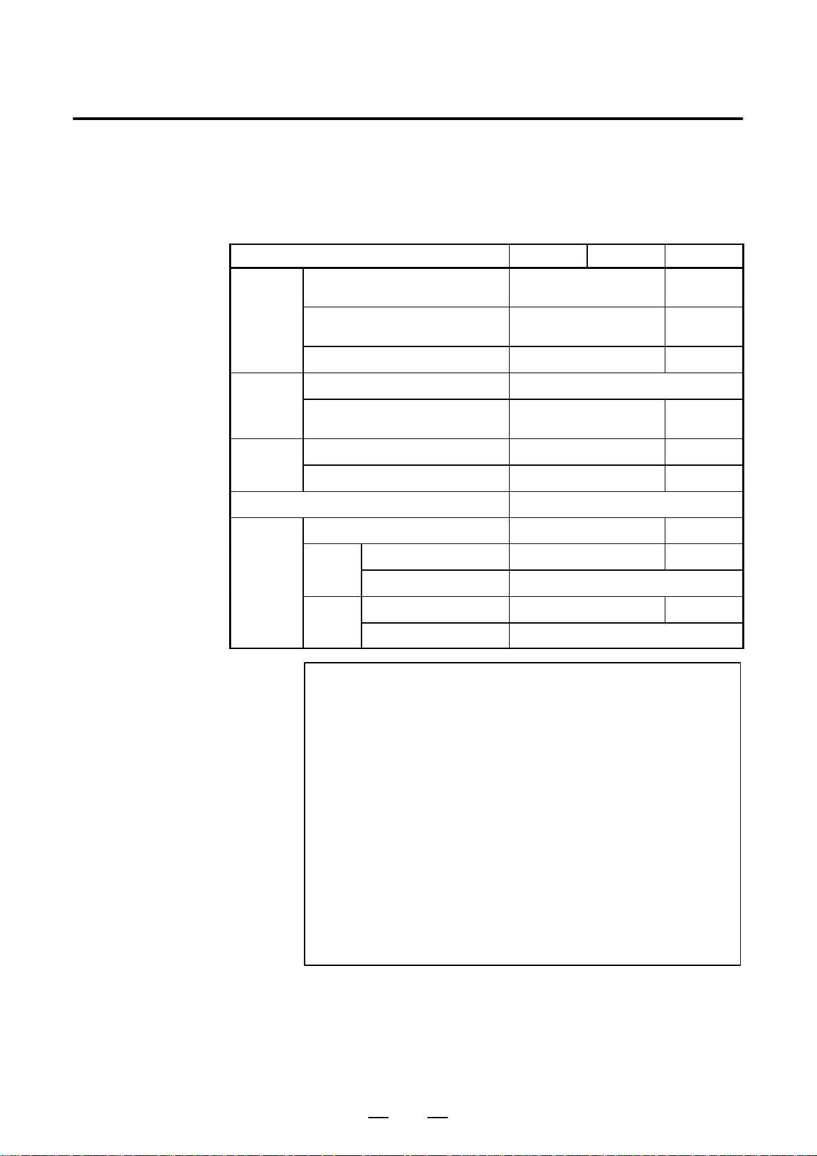
B–61863E/15
1.2
SUMMAR Y OF SPECIFICA TION OF LADDER PROGRAM
1. SEQUENCE PROGRAM
PMC SEQUENCE PROGRAM
T able 1.2 Summary of specification of ladder program (1)
CREATING PROCEDURE
Model
PMC
address
Ladder
program
compatibility
System
Basic commands Compatible
Function
commands
Interfaces between the PMC and CNC
(F and G)
Interfaces between the PMC and
machine (X and Y)
Others (R, A, C, K, D, T) Compatible Incompatible
ROM format (object) Incompatible (Note 1)
Source format (mnemonic) Compatible Incompatible
Divided system Not provided (Note 3) Provided
Undivided system Provided Not provided
DISP (SUB49) Not provided (Note 4) Provided
COM
(SUB9)
JMP
(SUB10)
Coil count specification Not provided (Note 5) Provided
COME (SUB29) specification Provided
Coil count specification Not provided (Note 5) Provided
JMPE (SUB30) specification Provided
PMC–PA1 PMC–PA3 PMC–P
Compatible Incompatible
Compatible Incompatible
(Note 2)
(Note 2)
(Note 2)
NOTE
1 The same ROM cannot be shared by different models. The
ROM must be rewritten using the offline programmer.
2 It is possible that convert the signal address by the
operation of “SIGNAL ADDRESS CONVERSION”
(APPENDIX G).
3 The setting item of system parameter IGNORE DEVIDE
CODE is not provided.
4 Use the DISPB (SUB41) command instead.
5 The range of the COM (SUB9) and JMP (SUB10)
commands cannot be specified with the number of coils.
Specify the range with the COME (SUB29) and JMPE
(SUB30) commands. If specify the number of coils, no error
messages will be displayed while editing, but “ALARM093”
will be displayed when send the data to RAM.
29
Page 64
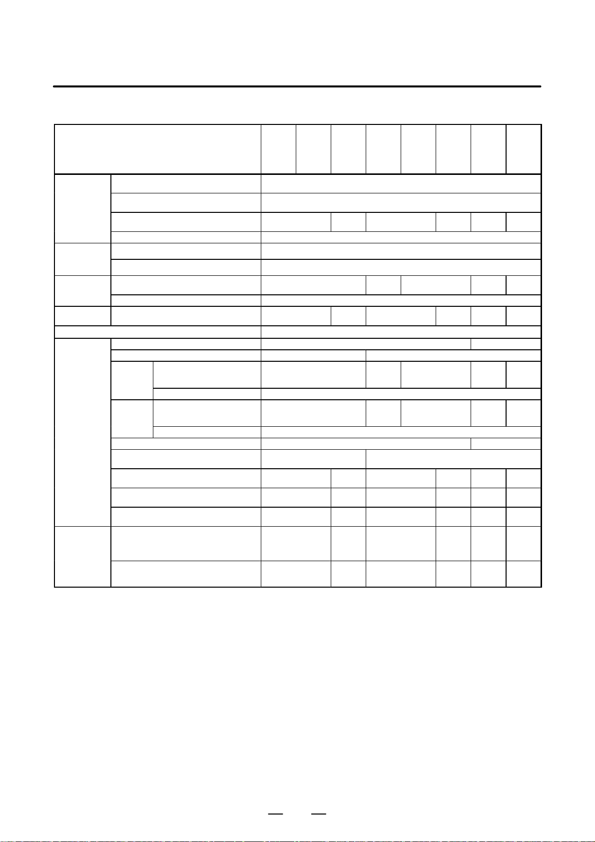
1. SEQUENCE PROGRAM
CREATING PROCEDURE
PMC SEQUENCE PROGRAM
T able 1.2 Summary of specification of ladder program (2)
B–61863E/15
PMC address
Ladder
program
compatibility
System
Structuring
Basic commands
Function
commands
Function
command
(for structured
programming)
PMC–
Model
PMC–
SA1
PMC–
SA2
PMC–
SA3/
SA5
PMC–SBPMC–
SB2
SB3/
SB4/
SB5/
PMC–
SC
SB6
Interfaces between the PMC and CNC (F and
G)
Interfaces between the PMC and machine (X
and Y)
Subprogram, label (P and L)
Others (R, A, C, K, D, T) Compatible (Note 1)
ROM format (object)
Source format (mnemonic)
Divided system
Undivided system Provided
Sub program
END3 (SUB48) Not provided Provided
DISP (SUB49) Not provided (Note 5) Provided
COM
(SUB9)
JMP
(SUB10)
FNC9X (SUB9X) Not provided Provided
MMCWR (SUB98), MMCWW (SUB99)
MMC3R (SUB88), MMC3W (SUB89) (Note 7)
MOVB (SUB43), MOVW (SUB44) ,
MOVN (SUB45)
DIFU (SUB57), DIFD (SUB58)
AND (SUB60), OR (SUB61)
NOT (SUB62), EOR (SUB59)
Commands for subprogram
END (SUB64) ,
CALL (SUB65), CALLU (SUB66) ,
SP (SUB71), SPE (SUB72)
Extended jump command
JMPB (SUB68), JMPC (SUB73)
LBL (SUB69)
Coil count specification
COME (SUB29) specification Provided
Coil count specification
JMPE (SUB30) specification Provided
Not provided Provided Not provided Provided
Not provided (Note 4) Provided
Unusable Usable Unusable Usable
Not provided (Note 6) Provided
Not provided (Note 6) Provided
Provided (Note 7) Provided
Not provided
Not provided
Not provided
Not provided
Not provided
Provided
Provided
Provided
Provided
Provided
Compatible (Note 8)
Compatible
Incompatible (Note 2)
Compatible (Note 3)
Not provided
(Note 4)
Compatible
Not provided
(Note 6)
Not provided
(Note 6)
Not provided
Not provided
Not provided
Not provided
Not provided
Provided
Provided
Provided
Provided
Provided
Not
provided
Provided
Un-
usable
Provided
Provided
Not
provided
Not
provided
Not
provided
Not
provided
Not
provided
Provided
provided
provided
(Note 6)
provided
(Note 6)
Provided
Provided
Provided
Provided
Provided
PMC–
SC3/
SC4
Not
Usable
Not
Not
30
Page 65

B–61863E/15
1. SEQUENCE PROGRAM
PMC SEQUENCE PROGRAM
CREATING PROCEDURE
NOTE
1 The internal relay and the data table in nonvolatile memory
for the PMC-SB3, SC, SC3 are extended, compared with
those for other models.
2 The same ROM cannot be shared by different models. The
ROM must be rewritten using the offline programmer.
However, the ROM for the PMC–SA2 can be used for the
PMC–SA3 and the ROM for the PMC–SB2 can be used for
the PMC–SB3.
3 The program can be converted by reinputting it after it is
output in a source format.
4 The setting item of system parameter IGNORE DEVIDE
CODE is not provided.
5 Use the DISPB (SUB41) command instead.
6 The range of the COM (SUB9) and JMP (SUB10)
commands cannot be specified with the number of coils.
Specify the range with the COME (SUB29) and JMPE
(SUB30) commands.
7 For the FS18A (PMC–SA1/SA2/SA3), only the MMC–III can
be used. For the FS18B, the MMC–III and MMC–IV can be
used.
For the FS21B (PMC–SA1/SA3), the MMC–IV can be used.
For the FS16i/18i/21i, the MMC–IV can be used.
For the FS16C/18C, the MMC–IV can be used.
8 In the PMC–SB4, SB6, and SC4, interface extension is
made. The extended portion of the interface is not
compatible with other PMCs.
31
Page 66
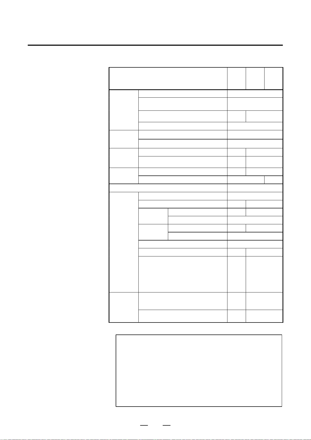
1. SEQUENCE PROGRAM
CREATING PROCEDURE
PMC SEQUENCE PROGRAM
T able 1.2 Summary of specification of ladder program (3)
B–61863E/15
Model
Series
PMC address Interfaces between the PMC and CNC (F and G)
Interfaces between the PMC and machine
(X and Y)
Subprogram, label (P and L)
Others (R, A, C, K, D, T)
Ladder ROM format (object)
program
compatibility
System Divided system
Structuring Subprogram
Basic commands
Function END3 (SUB48)
commands
Function
command
(for structured
programming)
Source format (mnemonic)
Undivided system
Step sequence
DISP (SUB49)
COM Coil count spesification
(SUB9)
JMP Coil count specification
(SUB10)
FNC9X (SUB9X)
LIBRY (SUB60), LEND (SUB61)
MMCWR (SUB98), MMCWW (SUB99)
MMC3R (SUB88), MMC3W (SUB89)
MOVB (SUB43), MOVW (SUB44)
MOVN (SUB45)
DIFU (SUB57), DIFD (SUB58)
AND (SUB60), OR (SUB61)
NOT (SUB62), EOR (SUB59)
S Command for subprogram
END (SUB64) , CALL (SUB65) , CALLU
(SUB66) , SP (SUB71) , SPE (SUB72)
S Extended jump command
JMPB (SUB68) , JMPC (SUB73) , LBL (SUB69)
COME (SUB29) specification
JMPE (SUB30) specification
PMC–
NA
(4046)
Not
provided
Provided Not provided
Not
provided
Unusable Usable
Provided Not provided
Provided Not provided
Provided Not provided
Provided Not provided
Not
provided
Not
provided
Not
provided
PMC–
NB
(4047)
(4048)
Incompatible
Compatible
Compatible (Note 1)
Incompatible (Note 2)
Compatible (Note 3)
Unusable Usable
Compatible
Provided
Provided
Provided
Provided
PMC–
NB2
(4048)
Provided
Provided
Provided
Provided
Provided
NOTE
1 Management of internal relay address and that of datatable
are different between the PMC–NB/NB2 and the PMC–NA.
2 The same ROM cannot be shared by different models.
The ROM must be rewritten using the offline programmer.
3 The data can be converted by outputting in the source
format and then inputting again.
Moreover, a part of functional instruction is not compatible
between PMC–NB/NB2 and PMC–NA.
32
Page 67

B–61863E/15
PMC SEQUENCE PROGRAM
T able 1.2 Ladder Compatibility (4)
1. SEQUENCE PROGRAM
CREATING PROCEDURE
Model
PMC address PMC–CNC interface (F, G) Compatible(NOTE 1)
PMC–machine interface (X, Y) Compatible
Area used by management software (K) K17 to K19 K900 to K909
Ladder ROM format (object) Not compatible Compatible(NOTE 2)
compatibility
Basic instruction Compatible
Functional
instruction
User program (C) Yes Y es(NOTE 3)
User program (step sequence) No Yes Y es (optional)
Sequence program automatic operation K17#2=1 K900#2=1 K900#2=0
Source format (mnemonic) Compatible
FNC9X(SUB9X)
MMC3R(SUB88)
MMC3W(SUB89)
MMCWR(SUB98)
MMCWW(SUB99)
FANUC Series 15–B FANUC Series 15i
PMC–NB PMC–NB2 PMC–NB6
Yes No
NOTE
1 Compatibility is not maintained for the interface unique to
the Series 15i.
2 The PMC–NB6 of the Series 15i is highly compatible with
the PMC–NB2 of the Series 15–B. The PMC–NB2 and
PMC–NB6 differ from each other in:
(1) Execution time–dependent ladder
As instruction execution becomes faster, the following
changes may occur in the execution timing:
S Change in the execution cycle of the second ladder
level
S Change in timing for the second–level split and
first–level execution
S Change in timing for ladder execution and I/O transfer
(2) Window functions
The functional instructions that can be used vary
between the PMC–NB2 and PMC–NB6. See Chapter 5,
”PMC Functional Instructions” in Part I, ”PMC Sequence
Program.”
(3) Screen manipulation
The operating procedure for the PMC screen for the
PMC–NB6 of the 15i varies slightly from that for the
PMC–NB2 of the 15–B.
See Chapter 7, ”PMC–NB6 Screen Manipulation,” in
Part II, ”PMC Manipulation.”
(4) Step sequence
For the PMC–NB6, the step sequence is optional.
3 The C option is necessary.
33
Page 68
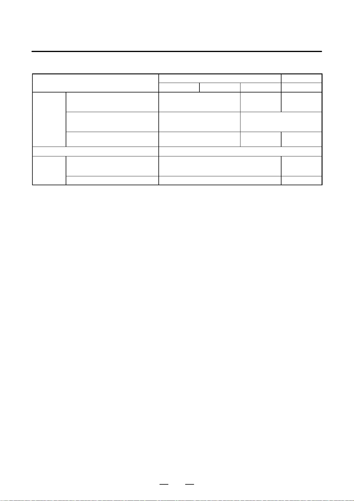
1. SEQUENCE PROGRAM
CREATING PROCEDURE
PMC SEQUENCE PROGRAM
T able 1.2 Ladder Compatibility (5)
B–61863E/15
Model
PMC address PMC–CNC interface (F, G) F0 to F255
PMC–machine interface (X, Y) X0 to X127
Area used by management software (K) K17 to K19 Changed to
Basic instruction Compatible
Function
instruction
END3
CTRB
MOVD
DISP Yes No
SA5 SB5 SB6 SB7
16i/18i/21i–A 16i/18i/21i–B
G0 to G255
Y0 to Y127
No Yes
Expanded to F0
to F51 1 and G0
X200 to X327
Y327 are added.
K900 to K909
The above table lists the differences to be noted on upward conversion to
the PMC–SB5, PMC–SB6, or PMC–SB7. Simple conversion in the
reverse direction cannot be performed generally because functions such
as the PMC address ranges are limited.
to G511
and Y200 to
Expanded to F0
to F767 and G0
to G767
Compatible
Expanded to
K900 to K919
(additional)
34
Page 69

1. SEQUENCE PROGRAM
B–61863E/15
PMC SEQUENCE PROGRAM
CREATING PROCEDURE
CAUTION
1 The above table does not contain simple addition of reserved areas for PMC addresses that
are not used by the ladder.
2 Execution time–dependent ladder
As instruction execution becomes faster, the following changes may occur in the execution
timing:
S Change in the execution cycle of the second ladder level
S Change in timing for the second–level split and first–level execution
S Change in timing for ladder execution and I/O transfer
A ladder which can be operated on the 16i/18i/21i–A must also be checked for operation on
the 16i/18i/21i–B system.
3 Changes in memory capacities required for a sequence program (PMC–SB7)
As described in Section 2.8, the memory capacities required for the system and
symbol/comment data have been changed. As a result, the capacity of flash ROM is increased
as compared with the PMC–SA5/SB5/SB6, even for the same source program. If a created
sequence program exceeds the capacity of flash ROM, add the step count option or delete
unnecessary symbols and comments.
4 Screen display and operation
The PMC–SB7 has much the same screen display/operation system as the
PMC–SA5/SB5/SB6. Some operations for the PMC–SA5/SB5/SB6 have been modified to
improve operability and functionality, however . The same goes for the PMC–SA1. For details,
see Chapter 1, ”SCREEN OPERATION FOR PMC–SA1/SB7” in Part V.
5 PMC parameter input/output (PMC–SB7)
With increase in size of a PMC parameter (T, C, K, and D areas), the data format used for
inputting PMC parameters from a memory card or floppy disk (FANUC Handy File) or outputting
them to it on the PMC I/O screen has been extended.
S PMC parameters output by the PMC–SA5/SB5/SB6 can be read by the PMC–SB7.
S PMC parameters output by the PMC–SB7 cannot be read by the PMC–SA5/SB5/SB6.
An extension relay (E area) has been added as a PMC address. A PMC parameter input or
output by the PMC–SB7 contains the E area. If a PMC parameter output by the PMC–SB7 is
read, the E area is initialized to the status when the PMC parameter is output.
35
Page 70

1. SEQUENCE PROGRAM
CREATING PROCEDURE
PMC SEQUENCE PROGRAM
B–61863E/15
1.3
WHAT IS A SEQUENCE PROGRAM?
This is paragraph outlines functions of a sequence program before
explaining the programming work.
A sequence program is a program for sequence control of machine tools
and other systems.
A program is defined as a processing procedure to enable CPU to execute
arithmetic processing.
This program is converted into a format (machine language instructions)
to enable CPU to execute decoding and arithmetic processing, and stored
into the RAM or ROM memory.
The CPU reads out instructions of the program stored into the memory
at high speed every instruction, and executes the program by arithmetic
operation.
The programming of a sequence program begins with the production of
a ladder diagram which serves as a processing procedure for arithmetic
processing by CPU.
This ladder program is produced using PMC instructions.
After producing the ladder diagram, the processing sequence of this
ladder diagram is converted into machine language instructions, and
stored into the memory (program input).
Conversion into the machine language instructions and storage into the
memory are done by the PMC programmer. The PMC programmer is a
function to produce a program.
The sequence program being stored into the memory is sequentially read
out into the PMC’s CPU every instruction at high speed and executed.
Fig. 1.3 shows this relation.
The CPU reads out input circuit signals of address X0.0 by RD X0.0
instruction, and sets them into an operation register. Then, the CPU
executes AND operation with internal relay states at address R10.0
according to the AND R10.1 instruction, and sets these results into the
operation register.
The CPU executes instructions at high speed and outputs arithmetic
results to the address Y0.0 output circuit.
36
Page 71
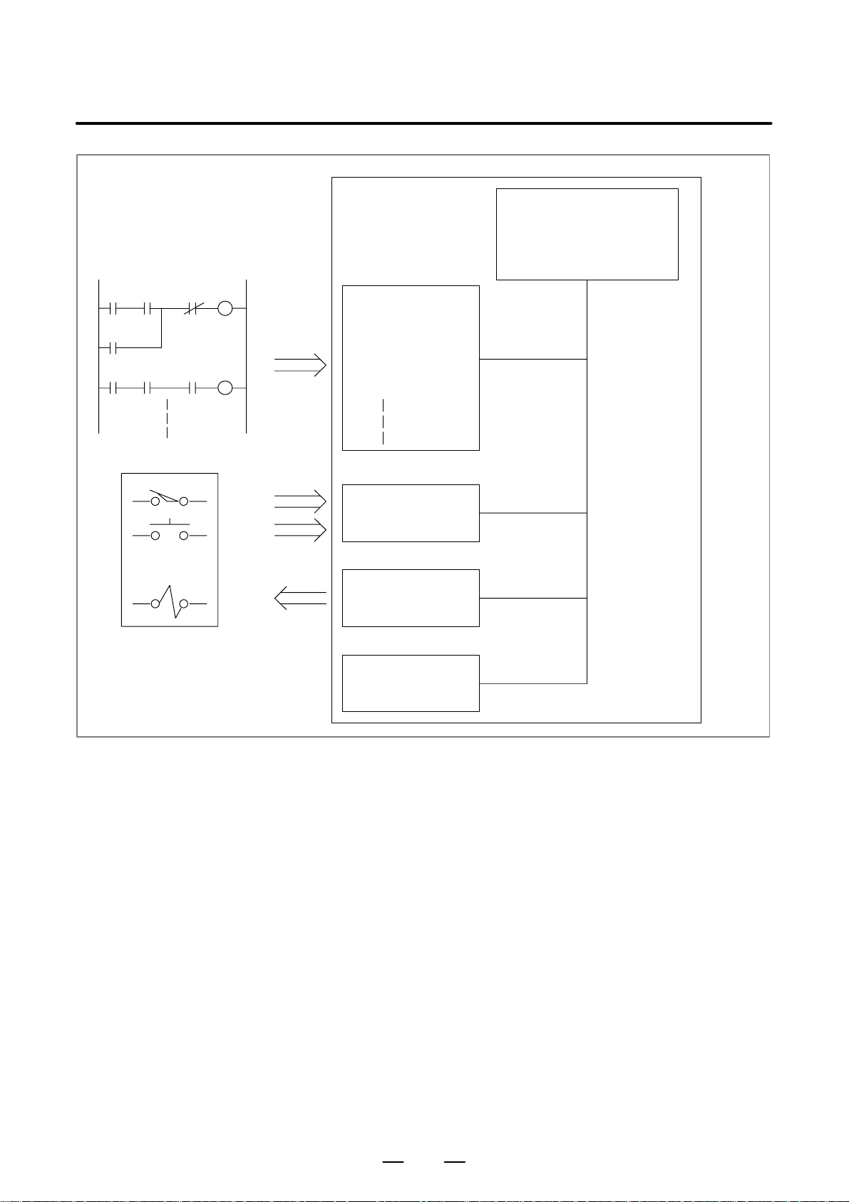
B–61863E/15
AB DW
X0.0 R10.1
C
X6.1
Controlled system, such as machine
tools and other systems
R20.3
Y0.0
Sequence
program input
PMC SEQUENCE PROGRAM
PMC (Programmable Machine Controller)
Sequence program memory
RD X0.0
AND R10.1
OR X6.1
AND.NOT R20.3
WRT Y0.0
Input circuit
X0.0
X6.1
1. SEQUENCE PROGRAM
CREATING PROCEDURE
CPU
Output circuit
Y0.0
Internal relay (RAM)
R10.1
R20.3
Fig. 1.3 Execution of sequence program by PMC
37
Page 72

1. SEQUENCE PROGRAM
CREATING PROCEDURE
PMC SEQUENCE PROGRAM
B–61863E/15
1.4
CREATION OF INTERFACE SPECIFICATIONS (STEPS 1 TO 3)
1.5
CREA TION OF LADDER DIAGRAM (STEP 4)
After deciding the control object specifications and calculating the
number of input/output signal points, create the interface specifications.
Use the input/output signal interface tables in the CONNECTION
MANUAL for the creation of the interface specifications. Enter the signal
names (within six characters) in the input/output signal interface table
according to the type of the connected signals. For the input/output
signals, see CONNECTION MANUAL.
Express the control operations decided by step 2 by use of the ladder
diagram (relay circuit diagram). For the functions of the timer, counter,
etc. which cannot be expressed with the relay symbols (i.e. the functional
instructions), express them with the symbols assigned to the functional
instructions.
In the offline programmer and built-in editing function, the sequence
program can be entered in the ladder diagram format from the keys of the
CRT/MDI panel or from the keys of the keyboard of the SYSTEM P
series.
Also, the entered sequence program can be output to the printer in the
ladder diagram format using the SYSTEM P series.
Therefore, entry can be performed while the ladder diagram is created on
the CRT screen at the time of sequence program entry. Thus no ladder
diagram may be prepared in advance.
However , in order to shorten the time occupied by the equipment for the
creation of the sequence program or to efficiently create the sequence
program, it is recommended to prepare the ladder diagram in advance.
The ladder diagram is used as a maintenance diagram by the personnel in
charge of maintenance in FANUC, the machine tool builder and end user
in the world. Therefore, the ladder diagram must be easy to understand.
Signal names (max. six characters) can be entered to the input/output
signals, comments (max. 30 characters) can be entered to the relay coil,
and comments (max. 30 characters) can be entered to the input/output
signals of the address tables at the time of entry of the sequence program.
Be sure to enter understandable signal names and comments as much as
possible.
38
Page 73
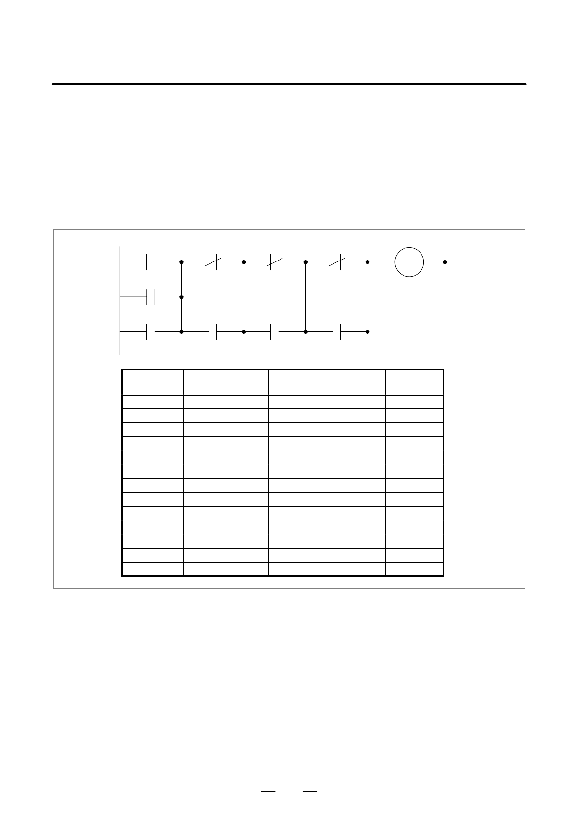
B–61863E/15
PMC SEQUENCE PROGRAM
1. SEQUENCE PROGRAM
CREATING PROCEDURE
1.6
CODING (STEP 5)
MF
F7.0
SF
F7.2
TF
F7.3
Step number Instruction
850 RD F7.0 MF
851 OR F7.2 SF
852 OR F7.3 TF
853 RD.NOT.STK F7.0 MF
854 OR R211.7 MFIN
856 AND.STK
857 RD.NOT.STK F7.2 SF
858 OR R211.5 SFIN
859 AND.STK
860 RD.NOT.STK F7.3 TF
861 OR R211.6 TFIN
862 AND.STK
863 WRT G4.3 FIN
In the coding, the contents of control expressed in the ladder diagram are
converted into PMC instructions. In the case of using the offline
programmer or ladder diagram editting, since sequence program entry can
be performed in the simple ladder diagram format, it is normally
unnecessary to perform coding.
Coding is necessary only when the sequence program is punched on a
paper tape and entered from the paper tape.
Examples of the ladder diagram and the coding are shown in Fig. 1.6.
MF
F 7.0
MFIN
R211.7
SF
F 7.2
SFIN
R211.5
TF
F 7.3
TFIN
R211.6
Address number,
bit number
FIN
Miscellaneous
function
finish signal
G4.3
Remark
Fig. 1.6
39
Page 74

1. SEQUENCE PROGRAM
CREATING PROCEDURE
PMC SEQUENCE PROGRAM
B–61863E/15
1.7
SEQUENCE PROGRAM ENTR Y (STEPS 6, 7)
The sequence program can be entered in five ways as follows:
(1) Entry with CRT/MDI keys
The sequence program is entered in the ladder diagram format by
pressing the keys of the CRT/MDI.
(2) Entry with keys of SYSTEM P series keyboard
The sequence program is entered in the mnemonic symbol by
pressing the keys of SYSTEM P series keyboard.
(3) Entry from PPR of SYSTEM P series
The sequence program punched on a paper tape is read out of the PPR
and stored in the memory of the SYSTEM P series.
(4) Entry form floppy disk of SYSTEM P series
This method is used when a completed sequence program is slightly
changed. The sequence program written in the floppy disk is stored
in the memory of SYSTEM P series.
(5) Entry form ROM Writer
This method is used when a completed sequence program is slightly
changed. The sequence program written in the ROM is stored from
the PMC Writer or FA Writer into P-G or Debugging RAM.
1.8
SEQUENCE PROGRAM CHECK AND WRITE INTO ROM (STEPS 8 TO 11)
Check the sequence program and write it into the ROM after check is over .
The sequence program can be checked in two ways.
(1) Check by simulator
Instead of the machine, connect a simulator (consisting of lamps and
switches). Instead of using input signals from the machine, enter
signals by turning on and off the switches according to the machine
movement. Check the output signals on the basis of the activation
of the lamps.
(2) Check by system operation
Perform checks by connecting the machine. Since it sometimes
happens that unexpected operations may be executed depending on
a sequence program, arrange for safety before starting operations.
(3) Writing into ROM
When check of the sequence program is over, write the sequence
program into the ROM. The ROMs to be used are as follows. Then,
the ROM into the CNC unit, and deliver it as a regular product to an
end user. Writing of the sequence program into the ROM,
maintenance and control thereof shall be performed by the machine
tool builder . For this purpose, FANUC provides the PMC Writer or
FA W riter as the ROM writer and the ROM or the ROM module that
is the PC board on which a ROM chip is mounted. Be sure to use
these devices for entering a sequence program in ROMs.
40
Page 75

B–61863E/15
PMC SEQUENCE PROGRAM
1. SEQUENCE PROGRAM
CREATING PROCEDURE
1.9
STORAGE AND CONTROL OF SEQUENCE PROGRAM (STEPS 12 TO 14)
(1) Storage and control of sequence program
After debugging, the sequence program should be stored and
controlled by the machine tool builder. It can be stored in the
following ways:
(a) Storing in ROM
The sequence program can be stored in the ROM. For control,
enter the drawing number, edition number, etc. of the machine
tool builder into the label provided in the ROM, and attach it to
the ROM for control. The same control is necessary for the ROM
for product.
(b) Storing in floppy disk
The sequence program can be stored in the floppy disk with
offline programmer. Many programs can be stored in one floppy
disk.
(c) Storing in paper tape
The sequence program can be stored in the form of a paper tape.
(d) Storing in FANUC floppy disk cassette
The sequence program can be stored in floppy disk cassette.
(2) Compiling and control of maintenance drawing
The sequence program can be output to the printer in the ladder
diagram format using the offline programmer or built-in editing
function. Be sure to attach the ladder diagram to the machine as a
maintenance drawing together with the machine tool magnetic
circuit diagrams, etc.
41
Page 76

2. SEQUENCE PROGRAM
SEQUENCE PROGRAM
2
PMC SEQUENCE PROGRAM
Since PMC sequence control handled by software and operates on
principles different from a general relay circuit, the sequence control
method must be fully understood in order to design the PMC sequence.
B–61863E/15
42
Page 77
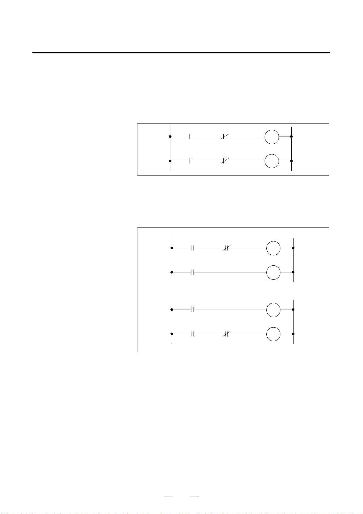
B–61863E/15
2. SEQUENCE PROGRAMPMC SEQUENCE PROGRAM
2.1
EXECUTION PROCEDURE OF SEQUENCE PROGRAM
In a general relay sequence circuit, each relay operates at approximately
the same time. In the figure below for example, when relay A operates,
the relay D and E operate at approximately the same time. (When both
contacts B and C are off.) In PMC sequence control, each relay of the
circuit operates sequentially. When relay A operates, relay D operates,
then relay E (see Fig. 2.1 (a)). Thus each relay operates in sequence which
can be written as a ladder diagram. (programmed sequence)
A B
D
A C
E
Fig. 2.1 (a) Circuit examples
Although the PMC sequential operation is performed at high speed, the
speed will change with the order to be executed.
Fig. 2.1 (b) (A) and (B) illustrate operations varying from the relay circuit
to PMC program.
(P.B)
A C
B
A
C
(A)
(P.B)
A
C
A C
B
(B)
Fig. 2.1 (b) Circuit examples
(1) Relay circuit
Operations are the same in both Fig. 2.1 (b) (A) and (B). Turning on
A (P .B) causes current to flow to coils B and C, which turns on B and
C. When C turns on, B turns off.
(2) PMC program
In Fig. 2.1 (b) (A), as in the relay circuit, turning on A (P.B) turns on
B and C, and after one cycle of the PMC sequence, turns off B. But
in Fig. 2.1 (b) (B), turning on A (P.B) turns on C, but does not turn
on B.
43
Page 78

2. SEQUENCE PROGRAM
PMC SEQUENCE PROGRAM
B–61863E/15
2.2
REPETITIVE OPERATION
The sequence program is executed from the beginning of coding to the
end of coding of the ladder diagram in the sequence written. When the
sequence program ends, the program starts over from the beginning. This
is called repetitive operation.
The execution time from the beginning to the end of the ladder diagram
is called the sequence processing time, which varies according to the
control scale (the number of steps) and the size of the 1st level sequence.
The shorter the process time is, the better the signal response becomes.
44
Page 79
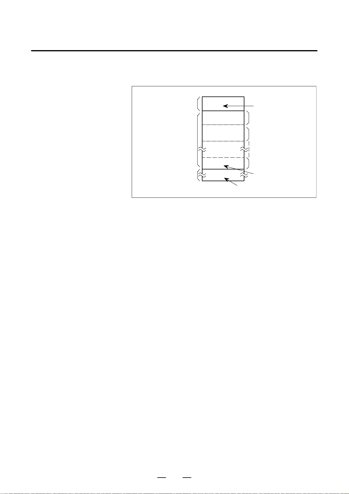
B–61863E/15
2. SEQUENCE PROGRAMPMC SEQUENCE PROGRAM
2.3
PRIORITY OF EXECUTION (1ST LEVEL, 2ND LEVEL AND 3RD LEVEL)
A sequence program consists of three parts: 1st level sequence, 2nd level
sequence and 3rd level sequence. The 3rd level sequence part is added
to the models usable the 3rd level sequence. (see Fig. 2.3 (a)).
Sequence program
1st level sequence part
2nd level sequence part
3rd level sequence part
Fig. 2.3 (a) Construction of sequence program
SUB 1
SUB 2
SUB 48
(Only the models usable the 3rd level sequence)
Specifies the end of the 3rd level sequence part.
Specifies the end of the
1st level sequence part.
Division 1
Division 2
Division n
Specifies the end of the
2nd level sequence part.
The 1st level sequence part operates every 8 ms (high–speed sequential
operation).
If the 1st level sequence part is long, the total operating time, including
the 2nd level sequence part, is extended. Therefore the 1st level sequence
part must be programmed to be processed in as short time as possible.
The 2nd level sequence part operates every 8×n ms. Here n is a dividing
number for the 2nd level sequence part. The 2nd level sequence part is
divided automatically when the sequence program is transferred to the
RAM for debugging in the CNC unit or it is written on ROM after the
program is created. The time for one cycle of the sequence program is
then displayed on the offline programmer screen.
The 3rd level sequence part operates during idle time of PMC.
(1) Division of the 2nd level sequence part
The 2nd level sequence part must be divided in order to execute the
1st level sequence part. For example a sequence program is executed
in the following sequence when the dividing number is n. (See Fig.
2.3 (b), 2.3 (c) )
After the last 2nd level sequence part (division n) is executed, the
sequence program is executed again from the beginning. Thus, when
the dividing number is n, the cycle of execution is 8mms (8ms×n).
The 1st level sequence operates every 8 msec, and the 2nd level
sequence every 8×n msec. If the steps of the 1st level sequence is
increased, the steps of the 2nd level sequence operating within 8 msec
becomes less, thereby increasing the dividing number and making
the processing time longer. Therefore, it is desirable to program so
as to reduce the 1st level sequence to a minimum.
In the, PMC–SA1, –SA2, –SB and –SB2, 1.25 ms of 8 ms is assigned
to execution of the 1st and 2nd level sequences. The remaining time
is assigned to NC processing.
In the PMC–SC, 5 ms of 8 ms is assigned to execution of the 1st and
2nd level sequences. The standard setting value is 5 ms when system
parameter LADDER EXEC = 100%. The remaining time is assigned
to execution of the 3rd level sequence and the program.
45
Page 80
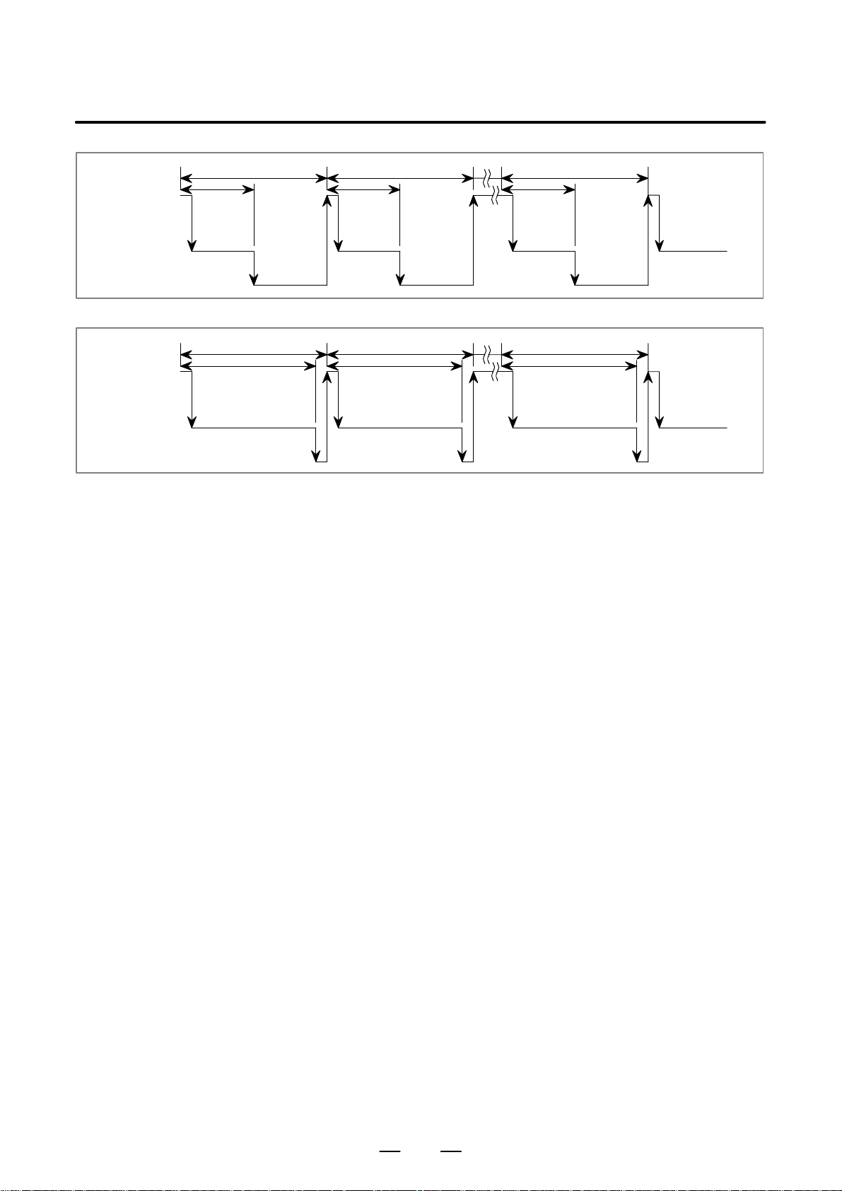
2. SEQUENCE PROGRAM
8ms 8ms 8ms
1st level
1.25ms 1.25ms 1.25ms
PMC SEQUENCE PROGRAM
B–61863E/15
2nd level
NC processing
Fig. 2.3 (b) Sequence in which the Sequence Program Is Executed (PMC–SA1, –SA2, –SB and –SB2)
8ms 8ms 8ms
1st level
2nd level
3rd level, program execution,
and displaying the PMC screen
Fig. 2.3 (c) Sequence in which the Sequence Program Is Executed (PMC–SC)
5ms 5ms 5ms
Division 1Division 1 Division nDivision 2
Division 1Division 1 Division nDivision 2
(2) 1st level sequence part
Only short–width pulse signals are processed. These signals include
emergency stop, overtravel of each axis, reference point return
deceleration, external deceleration, skip, measuring position arrival
and feed hold signals.
(3) 3rd level sequence
The purpose of the 3rd level sequence is to execute such programs
as display processing or control status monitor having no direct
relation to the machine control (operator message, alarm display,
etc.), to lighten the load of the 2nd level program having a direct
relation to the machine control by transferring former programs to the
3rd level, and to shorten the PMC execution time (cycle time).
For PMC–RC, when 3rd level program is not used, command SUB
48 (END3) following SUB 2 instruction.
(4) Divided system and undivided system
There is a model can use the divided system and undivided system
among the PMCs. In the divided system, a ladder program is divided
before being executed if all ladder program run regardless of the
sequence state (see Fig. 2.3 (d)).
For an actual ladder program, not all ladder program run. The PMC
cannot therefore be used effectively.
The PMC can execute the ladder program in the system for terminating
one cycle of the program using the time to execute the actual ladder
program (undivide system) as well as in the divided system.
The time required for the one cycle can be reduced by the effective
use of jump instructions in the ladder program.
Since the sequence using many functional instructions requires a lot
of processing time, the undivided system should be specified so that
the PMC is used more effectively (see Fig. 2.3 (e)).
To operate the PMC in the undivided system, set system parameter
IGNORE DIVIDE CODE to YES.
The PMC model usable only the undivided system, does not have
setting system parameter IGNORE DIVIDE CODE. It is always
46
Page 81
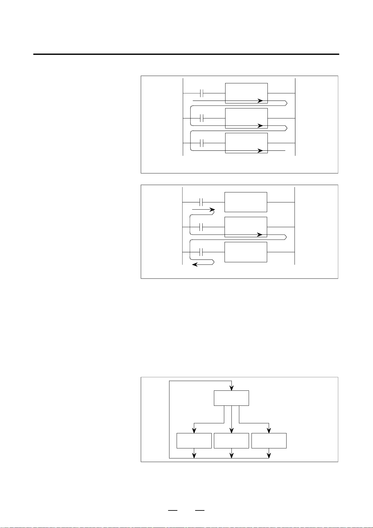
B–61863E/15
2. SEQUENCE PROGRAMPMC SEQUENCE PROGRAM
operated under the undivided system.
A
B
C
The ladder program is divided if all functional instructions are
executed regardless of execution of an actual ladder program.
Fig. 2.3 (d) Divisions in the divided system
A
B
C
Functional
instruction
Functional
instruction
Functional
instruction
Functional
instruction
Functional
instruction
Functional
instruction
Execution of an actual ladder program when A = 0, B = 1, and C = 0.
Fig. 2.3 (e) Execution of a ladder program
(a) Example of effective use of the undivided system
Example 1)
Many M codes are usually used. Since more than one M code
is not used in the same block, the decoded M code is divided
into several parts. Machine instructions are used as these
decoded parts.
The M code is divided into M codes having two digits such
as M21, M22, M24, M28, and so on.
Example 2)
To reduce the number of ROM types using the same ladder
program for multiple machines, a PMC parameter must be
specified so that any of the following ladder program run.
Ladder A
Ladder B2Ladder B1 Ladder B3
(Ladder common to all machines)
(Selected by a PMC parameter)
(Ladders dedicated
to each machine)
47
Fig. 2.3 (f)
Page 82
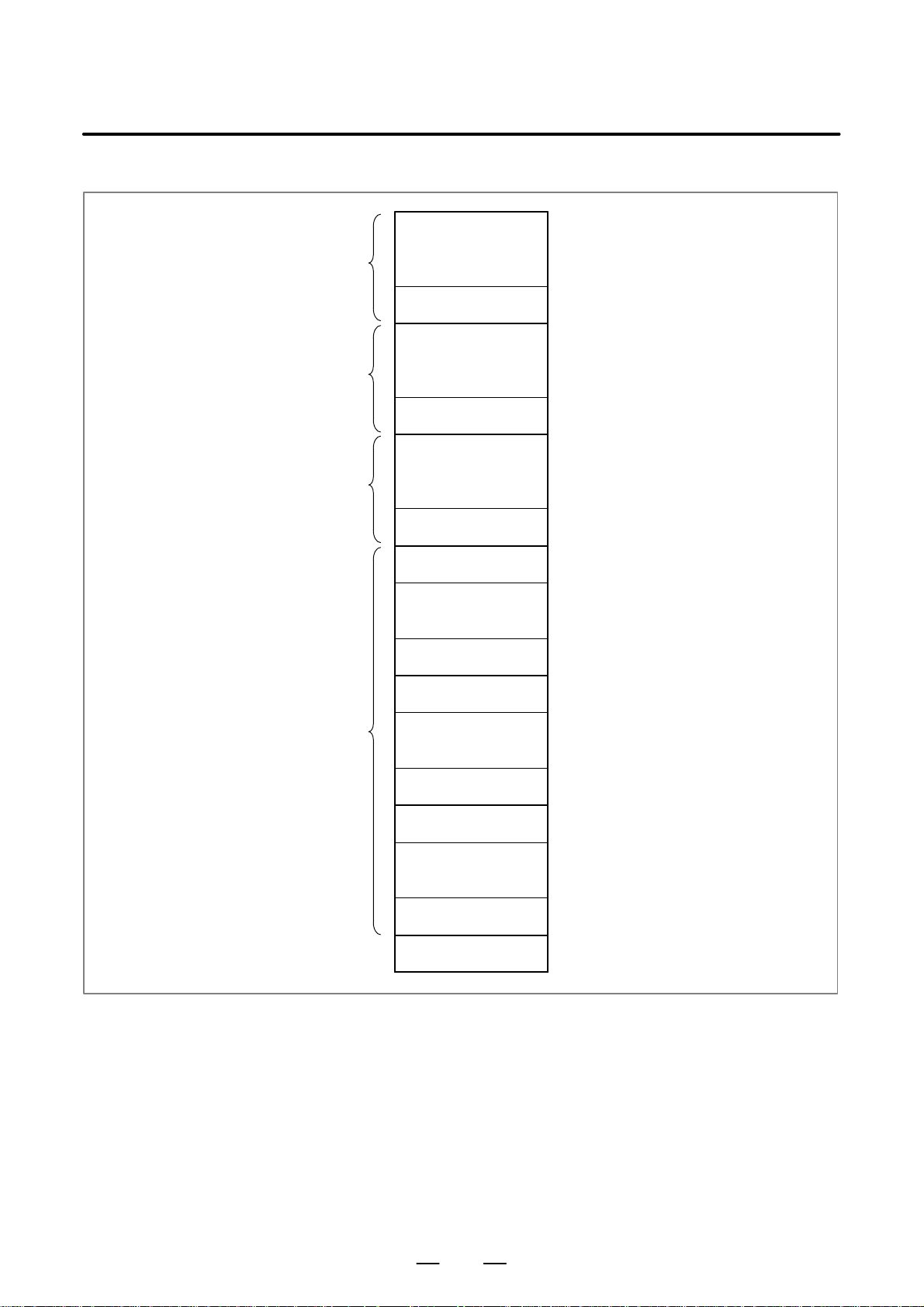
2. SEQUENCE PROGRAM
1st level sequence part
2nd level sequence part
3rd level sequence part
(Only about the PMC
model usable the 3rd
level sequence)
PMC SEQUENCE PROGRAM
B–61863E/15
(5) Construction of sequence program in the case of using Sub–program.
END1 (SUB 1)
END2 (SUB 2)
END3 (SUB 48)
SP
D Sub program must be written between 2nd
D level program and 3rd level program.
Sub program
End of sequence program
SPE
SP
SPE
SP
SPE
END
Fig. 2.3 (g)
D The end of sequence program is expressed
D by END command.
48
Page 83
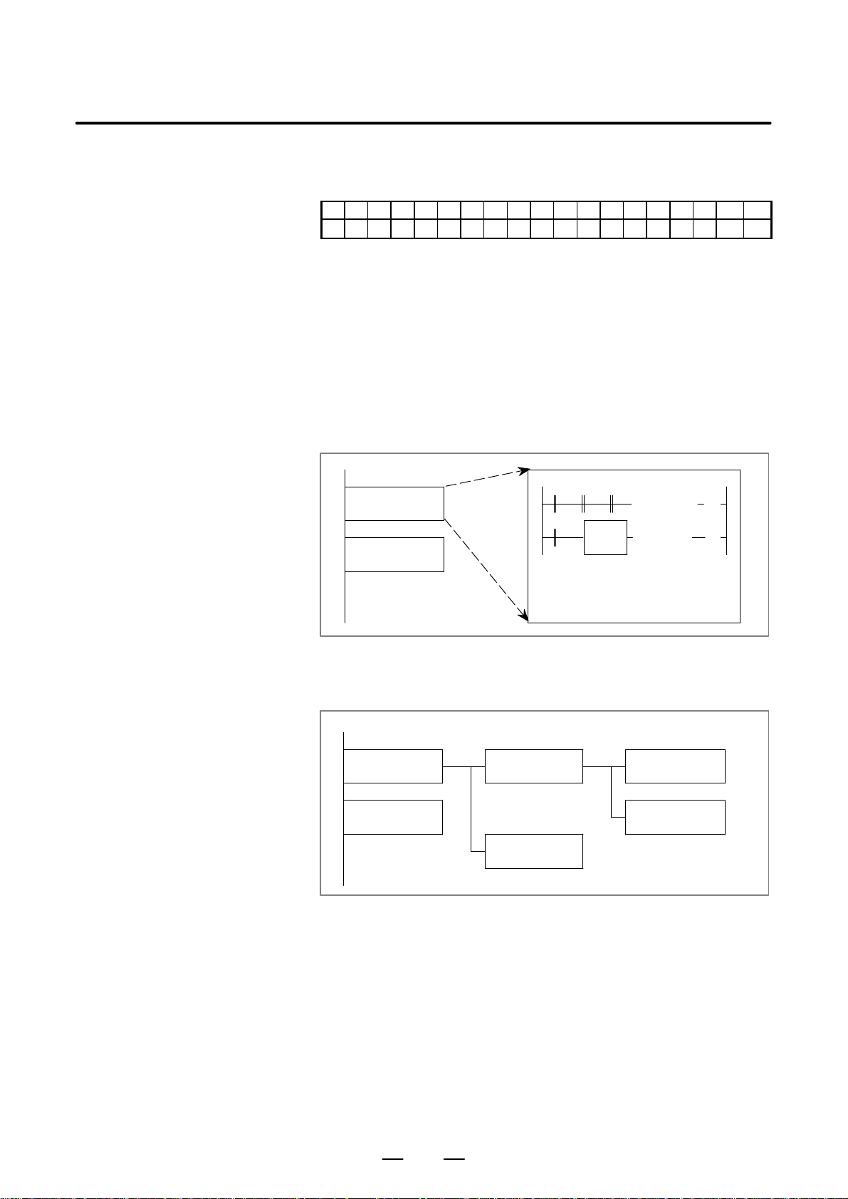
B–61863E/15
2. SEQUENCE PROGRAMPMC SEQUENCE PROGRAM
2.4
SEQUENCE PROGRAM STRUCTURING
Ę : Can be used
: Cannot be used
PA1 PA3 SA1 SA2 SA3 SA5 SB SB2 SB3 SB4 SB5 SB6 SB7 SC SC3 SC4 NB NB2 NB6
Ę Ę Ę Ę Ę Ę Ę Ę Ę Ę Ę Ę Ę
With the conventional PMC, a ladder program is described sequentially.
By employing a ladder language that allows structured programming, the
following benefits are derived:
D A program can be understood and developed easily.
D A program error can be found easily.
D When an operation error occurs, the cause can be found easily.
Three major structured programming capabilities are supported.
(1) Subprogramming
A subprogram can consist of a ladder sequence as the processing unit.
Job A
FUNC
Job B
D
D
D
DDD
DDD
f
f
(2) Nesting
Ladder subprograms created in (1) above are combined to structure
a ladder sequence.
Main Program Sub Program1 Sub Program2
Job A Job A1 Job A11
D
Job An
D
D
Job A12
Job B
49
Page 84
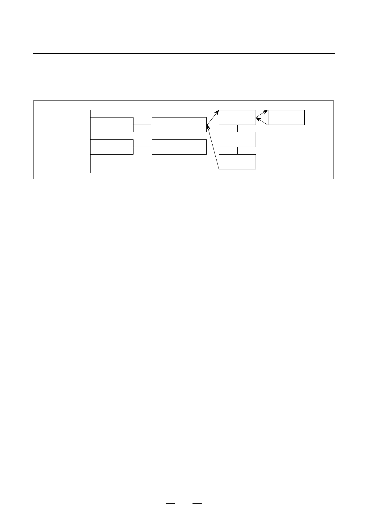
2. SEQUENCE PROGRAM
Main Program Sub Program1
PMC SEQUENCE PROGRAM
B–61863E/15
(3) Conditional branch
The main program loops and checks whether conditions are satisfied.
If a condition is satisfied, the corresponding subprogram is executed.
If the condition is not satisfied, the subprogram is skipped.
STATE1 PROCESS1
STATE2 PROCESS2
D
D
D
For details, see Chapter 9.
PROCESS11
PROCESS12
PROCESS13
PROCESS11
50
Page 85
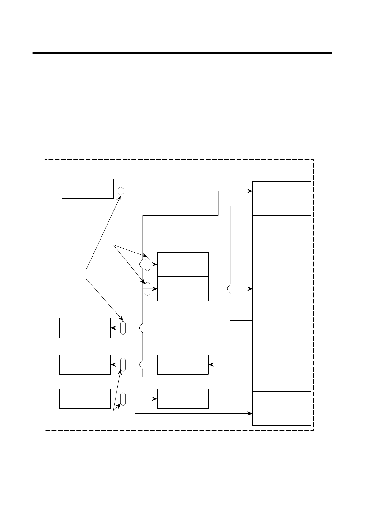
B–61863E/15
2. SEQUENCE PROGRAMPMC SEQUENCE PROGRAM
2.5
PROCESSING I/O SIGNALS
CNC
Input memory of CNC
Input signals from
CNC
Transmitted at the
start of 2nd level
Input signals (M function, T function, etc.) from the CNC and those (cycle
start, feed hold, etc.) from the machine tool are sent to the PMC.
Signals for the CNC (cycle start, feed hold, etc.) and those for the machine
tool (tunret rotation, spindle stop, etc.) are output from the PMC.
Fig. 2.4 shows the relationship between these signals and the PMC.
Input signals are entered in the input memory of PMC and output signals
are issued from PMC.
As shown in Fig. 2.5, the input signals are synchronized only in the 2nd
level sequence part.
PMC
Sequence program
1st level
sequence part
2nd level synchronous
input signal memory
Transmitted every 8 ms
Output memory of CNC
Output signals to
CNC
MT
Output signals to
machine tool
Input signals from
machine tool
Transmitted
every 2 ms
Input signals from
CNC
Input signals from
machine tool
Output signalmemory
Output signals to the
machine
Input signal memory
Input signals from
machine
2nd level
sequence part
3rd level
sequence part
Fig. 2.5 PMC I/O signals
51
Page 86

2. SEQUENCE PROGRAM
PMC SEQUENCE PROGRAM
B–61863E/15
2.5.1
Input Signal Processing
(1) Input memory of CNC
The input signals from CNC are loaded in memory of CNC and are
transferred to the PMC at intervals of 8 ms.
Since the 1st level and the 3rd level sequence part directly refer to
these signals and process operations, these signals do not
synchronize with input signals from the CNC.
See item 2.5.3.
(2) Input signals from machine tool (DI/DO card)
Input signals from the machine tool are transferred to the input signal
memory from the input circuit (DI/DO card). 1st level and 3rd level
sequence part directly processes by reading signals loaded in the
input signal memory.
(3) Input signal memory
The input signal memory stores signals transferred from the machine
tool at intervals of 2 ms period.
The PMC 1st level sequence part and 3rd level sequence part are used
to read and process signals stored in this memory.
In this case, state of signals set in the input signal memory
synchronizes with that of 1st level sequence part but not with that of
3rd level sequence part.
See item 2.5.3.
(4) 2nd level synchronous input signal memory
The 2nd level synchronous input signal memory stores signals
processed by the 2nd level sequence section.
State of the signals set in this memory synchronizes with that of the
2nd level sequence part.
Input signal memory and input signals from the CNC are transferred
to the 2nd level synchronous input signal memory only at the
beginning of execution of the 2nd level sequence section. Therefore,
the status of the 2nd level synchronous input signal memory does not
change from the beginning to end of the execution of the 2nd level
sequence part.
Programmer function makes the processing so that the 1st level
sequence section and 3rd level sequence section use the input signal
memory and input signals from the CNC side and the 2nd level
sequence section uses the 2nd level synchronous input signal
memory.
2.5.2
Output Signal Processing
(1) CNC output memory
The output signals are transferred from the PMC to the CNC output
memory at intervals of 8 ms.
(2) Output signals to machine tool (DI/DO card)
Output signals to the machine tool are transferred from the PMC
output signal memory to the machine tool.
(3) Output signal memory
The output signal memory is set by the PMC sequence program.
Signals stored in this memory are transferred to the machine side at
a 2 ms period.
52
Page 87
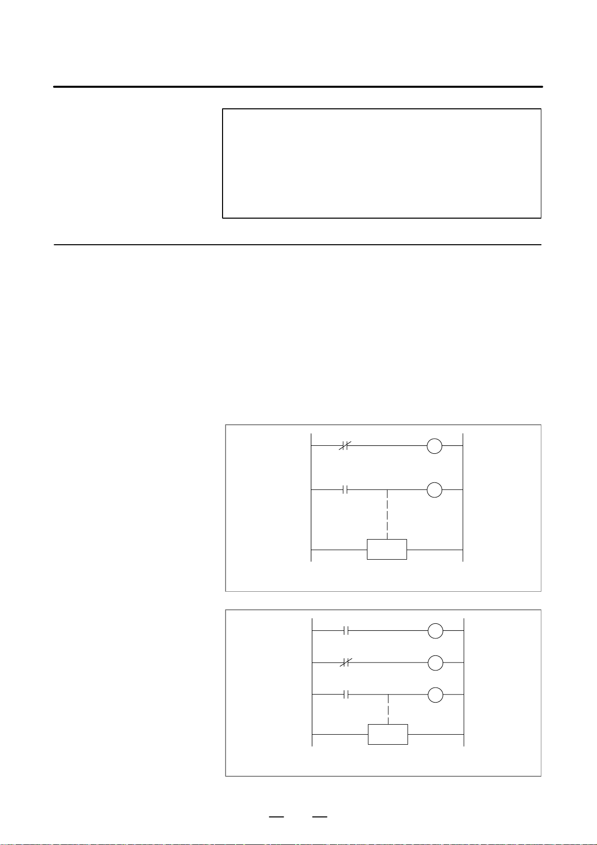
B–61863E/15
2. SEQUENCE PROGRAMPMC SEQUENCE PROGRAM
NOTE
The status of the CNC input memory, input signals from
machine, CNC output memory and output signals to
machine can be checked by using the PC self–diagnosis
function.
The self–diagnosis number specified is the address number
used by the sequence program.
2.5.3
I/O Signals to CNC
Signals input from the CNC are transferred to the PMC at intervals of 8
ms.
Signals output to the CNC are transferred from the PMC at intervals of
8 ms.
PMC I/O signals are generally transferred at intervals of 8 ms.
In this case, note that state of the input signals from the CNC does not
synchronize with that of the 1st level sequence program and the 2nd level
sequence program. By this reason, if an input signal from the CNC may
change while execution of the 1st level sequence program, for example,
some trouble may occur like example in Fig. 2.5.3 (a).
To avoid such trouble, write the state of signal TF in an internal relay at
the start of the 1st level sequence, then the 1st level sequence program
shall refer to the internal relay as signal TF. See Fig. 2.5.3 (b).
TF
TF
END 1
W1
W2
If after TF=0 is load, signal state changes to TF=1,
state of W1=1 and W2=1 may momentary occur
Fig. 2.5.3 (a)
TF
TFM
TFM
END 1
Make signal TF synchronized one, and state of
W1=1 and W2=1 may not occur.
Fig. 2.5.3 (b)
TFM
W1
W2
53
Page 88
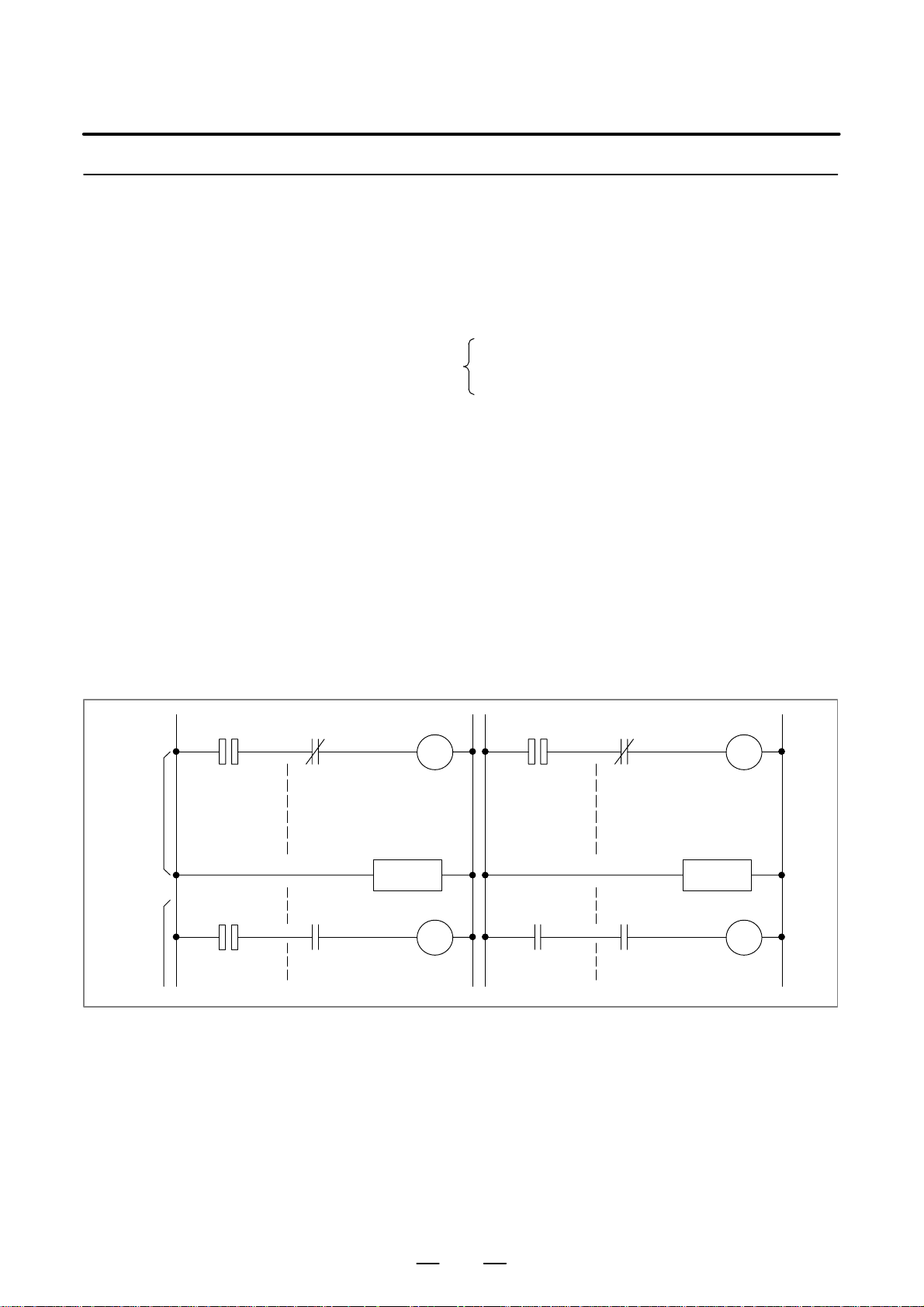
2. SEQUENCE PROGRAM
PMC SEQUENCE PROGRAM
B–61863E/15
2.5.4
Difference of Status of Signals between 1st Level and 2nd Level
The status of the same input signal may be different in the 1st level and
2nd level sequences. That is, at 1st level, processing is performed using
input signal memory and at 2nd level, processing is performed using the
2nd level synchronous input signal memory . Therefore, it is possible for
a 2nd level input signal to delay by a cycle of 2nd level sequence execution
at the worst, compared with a 1st level input signal.
This must be kept in mind when writing the sequence program.
A.M ON (short time width pulse signal)
Signal statesO
B OFF
COF
Differences drawn in Fig. 2.5.4 (a) and Fig. 2.5.4 (b) when the 1st level
sequence has been executed are as follows:
(a) Fig. 2.5.4 (a)
W2 may not be 1 even when W1=1. (Because the A.M signal may
be different at the 1st and 2nd levels.)
(b) Fig. 2.5.4 (b)
If W1=1, W2=1.
When performing the sequence shown in Fig. 2.5.4 (a), proceed
as follows:
At 1st level, perform a high–speed sequence when the A.M signal
changes (operating).
At 2nd level, perform sequence processing when the A.M signal
does not change (stopped).
1st Level
2nd Level
A.M B
W1
END 1
A.M C
W2
Fig. 2.5.4 (a) Fig. 2.5.4 (b)
A.M B
W1 C
W1
END 1
W2
54
Page 89

B–61863E/15
2. SEQUENCE PROGRAMPMC SEQUENCE PROGRAM
2.5.5
Notes on Input/Output Signals Over a Network
Input/output signals (assignment to the R, D, and E addresses) over a
network (such as the Ethernet, I/O Link–II, PROFIBUS, DEVICENET,
and FL–NET) are updated asynchronously with the execution of the PMC
sequence program. Therefore, when using the signals updated over a
network in the PMC sequence program, keep the following in mind.
(1)Notes on an input signal
When an input signal over a network is referenced at multiple points
in the PMC sequence program, there are not guarantees that the same
value can be referenced even in the same cycle in the sequence
program.
T o guarantee that the same value can be referenced as an input signal
in the same cycle in the sequence program, save the status of the input
signal in the internal relay or the like.
(2)Notes on an output signal
An output signal over a network may be forwarded to a slave unit
during the operating cycle of the PMC sequence program. Be careful
when multiple signals are referenced on the slave unit side.
(3)Notes on multibyte data
The data concurrency (indicating that data is not broken) of multibyte
data input or output over a network is not guaranteed.
To ensure the data concurrency, the sequence processing performed
during data input and output must not cause data to be broken.
55
Page 90

2. SEQUENCE PROGRAM
PMC SEQUENCE PROGRAM
B–61863E/15
2.6
INTERLOCKING
Interlocking is externally important in sequence control safety.
Interlocking with the sequence program is necessary. However,
interlocking with the end of the electric circuit in the machine tool
magnetics cabinet must not be forgotten. Even though logically
interlocked with the sequence program (software), the interlock will not
work when trouble occurs in the hardware used to execute the sequence
program. Therefore, always provide an interlock inside the machine tool
magnetics cabinet panel to ensure operator safety and to protect the
machine from damage.
56
Page 91

B–61863E/15
2. SEQUENCE PROGRAMPMC SEQUENCE PROGRAM
2.7
SEQUENCE PROGRAM PROCESSING TIME
The exact sequence processing time is displayed on the CR T screen when
the sequence programs have been completed. The time is 2nd level
sequence division number n x 8 ms.
This section explains how to estimate processing times that are important
in sequence control when the ladder diagram, the basis of sequence
program control, is almost complete.
(1) Processing time calculation units
Sequence processing time estimation is based on the basic
instructions (AND, OR, etc.). The execution time for a functional
instruction is given in the execution constant column of the
Functional Instruction Table. Converted to a basic instruction; that
is the number of basic instructions that a functional instruction is
equivalent to.
Processing time is determined for the above using the equation in
item below.
(2) Processing time estimation equation
The number of division (n) in the 2nd level sequence is determined
and the processing time is calculated using the following equations:
Sequence processing time =
n (number of division) 8 msec
n=
(ET)µsec – (HT)µsec
(LT) µsec
+1
(n is an integer, fractions are omitted)
(a) (HT) is the execution time for the 1st level sequence section.
(HT)={(number of steps in basic instruction)+(sum of functional
instruction execution time constants) 10} (IT) µsec
Execution time constant for END.1 (206) must be included in HT.
(b) (LT) is the execution time for the 2nd level sequence section.
(LT)={(number of steps in basic instruction)+(sum of functional
instruction execution time constants) 10} (IT) µsec
END.2 execution time (127) must be included.
(c) (ET) is the execution time assigned to the 1st and 2nd level parts
out of 8 ms.
For PMC–SB
(ET) = 1.25 ms = 1250µs
For PMC–SC (standard setting when LADDER EXEC = 100%)
(ET) = 5 ms = 5000µs
(d) IT) is the execution constant for calculating the processing time.
The value is as follows:
(IT) = 0.15µs
57
Page 92

2. SEQUENCE PROGRAM
PMC SEQUENCE PROGRAM
(3) Processing time calculation example (for PMC–SB)
(a) 1st level sequence
Basic instruction: 100 steps
Functional instruction:
CTR: 2 times,
COMPB: 2 times
CTR execution time constant: 26
COMPB execution time constant: 24
END.1 execution time constant: 206
HT={100+(26 2+24 2+206) 10} 0.15 =474 µsec
(b) 2nd level sequence
Basic instruction: 6,000 steps
Functional instruction:
TMR: 35 times,
DECB: 25 times,
ROTB: 2 times
TMR execution time constant: 23
DECB execution time constant: 20
ROTB execution time constant: 33
END.2 execution time constant: 32
LT={6,000+(23 35+20 25+33 2+32) 10} 0.15=3004.5msec
B–61863E/15
(c) Determination of the number of divisions (n)
3004.5 µsec
n=
1250µsec – 474 µsec
+1 = 4.87
(d) Processing time calculation
Sequence processing time=4 (number of division) 8 msec=32
msec
NOTE
For the PMC–SB/SC, see the execution time constant of
each function instruction in T able 5 (b) in Section I–5, ”PMC
FUNCTION INSTRUCTIONS.”
58
Page 93
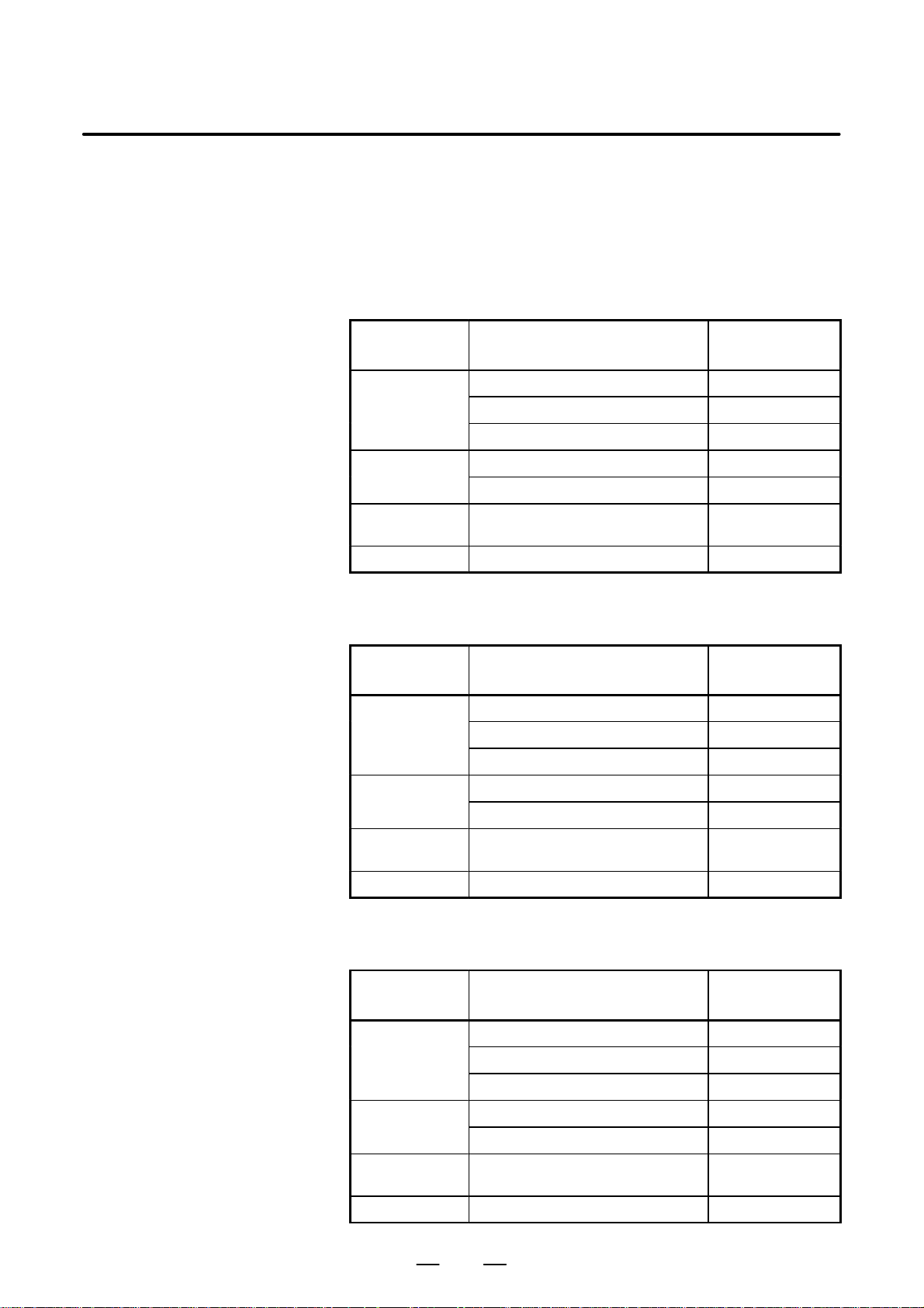
B–61863E/15
2. SEQUENCE PROGRAMPMC SEQUENCE PROGRAM
2.8
SEQUENCE PROGRAM MEMOR Y CAPACITY
The following tables list memory capacities required for a sequence
program. Create a sequence program so that the total capacity of these
items does not exceed the sequence program memory capacity.
T able 2.8 (a) PMC–SB7
Type
Ladder (Note 2)
Symbol/comment
(Note 2)
Message (Note 2) One half–width alphanumeric character in
Others System used area About 15K bytes
Basic instruction 4 bytes
Functional instruction 4 bytes
Functional instruction parameter 4 bytes
One symbol or comment 24 bytes
One half–width character in a comment 1 byte (Note 3)
a message
Item
T able 2.8 (b) PMC–SB4/SB6/SC4/NB2/NB6
Memory capacity
(Note 1)
1 byte (Note 4)
Type
Ladder (Note 2)
Symbol/comment
(Note 2)
Message (Note 2) One half–width alphanumeric character in
Others System used area About 4K bytes
Basic instruction 4 bytes
Functional instruction 4 bytes
Functional instruction parameter 4 bytes
One symbol or comment 12 bytes
One half–width character in a comment 1 byte
a message
Item
Memory capacity
(Note 1)
1 byte (Note 4)
T able 2.8 (c) PMC–SB6 (I/O links expanded)
Type
Ladder (Note 2)
Symbol/comment
(Note 2)
Item
Basic instruction 4 bytes
Functional instruction 4 bytes
Functional instruction parameter 4 bytes
One symbol or comment 12 bytes
One half–width character in a comment 1 byte
Memory capacity
(Note 1)
Message (Note 2) One half–width alphanumeric character in
a message
Others System used area About 9.5K bytes
1 byte (Note 4)
59
Page 94

2. SEQUENCE PROGRAM
PMC SEQUENCE PROGRAM
T able 2.8 (d) PMC–SA1/SA3/SA5/SB/SB2/SB3/SB5/SC/SC3/PA1/PA3/NB
B–61863E/15
Type
Ladder (Note 2)
Symbol/comment
(Note 2)
Message (Note 2) One half–width alphanumeric character in
Others System used area About 2K bytes
Basic instruction 4 bytes
Functional instruction 4 bytes
Functional instruction parameter 4 bytes
One symbol or comment 10 bytes
One half–width character in a comment 1 byte
a message
Item
Memory capacity
(Note 1)
1 byte (Note 4)
NOTE
1 The total capacity of a sequence program (including all
items such as ladder, symbols/comments, and messages)
cannot exceed the capacity of the sequence program
storage memory. If the ladder, symbol/comment, or
message area is large, the size of another area may be
limited.
2 The PMC programmer may adjust arrangement of the areas
in the sequence program memory to improve processing
efficiency. As a result, up to 1K (1024) bytes may be added
to the total capacity of each type of data.
3 A full–width character requires double the capacity.
4 For each of half–width katakana characters and special
characters, and full–width hiragana characters, kanji
characters, and special characters, a capacity of 1 byte is
required per digit of the notation (including characters
preceding and following the character such as @) by
character code input. For details of notation by character
code input, refer to the paragraph describing DISPB in
Chapter 5, “FUNCTIONAL INSTRUCTIONS.”
60
Page 95
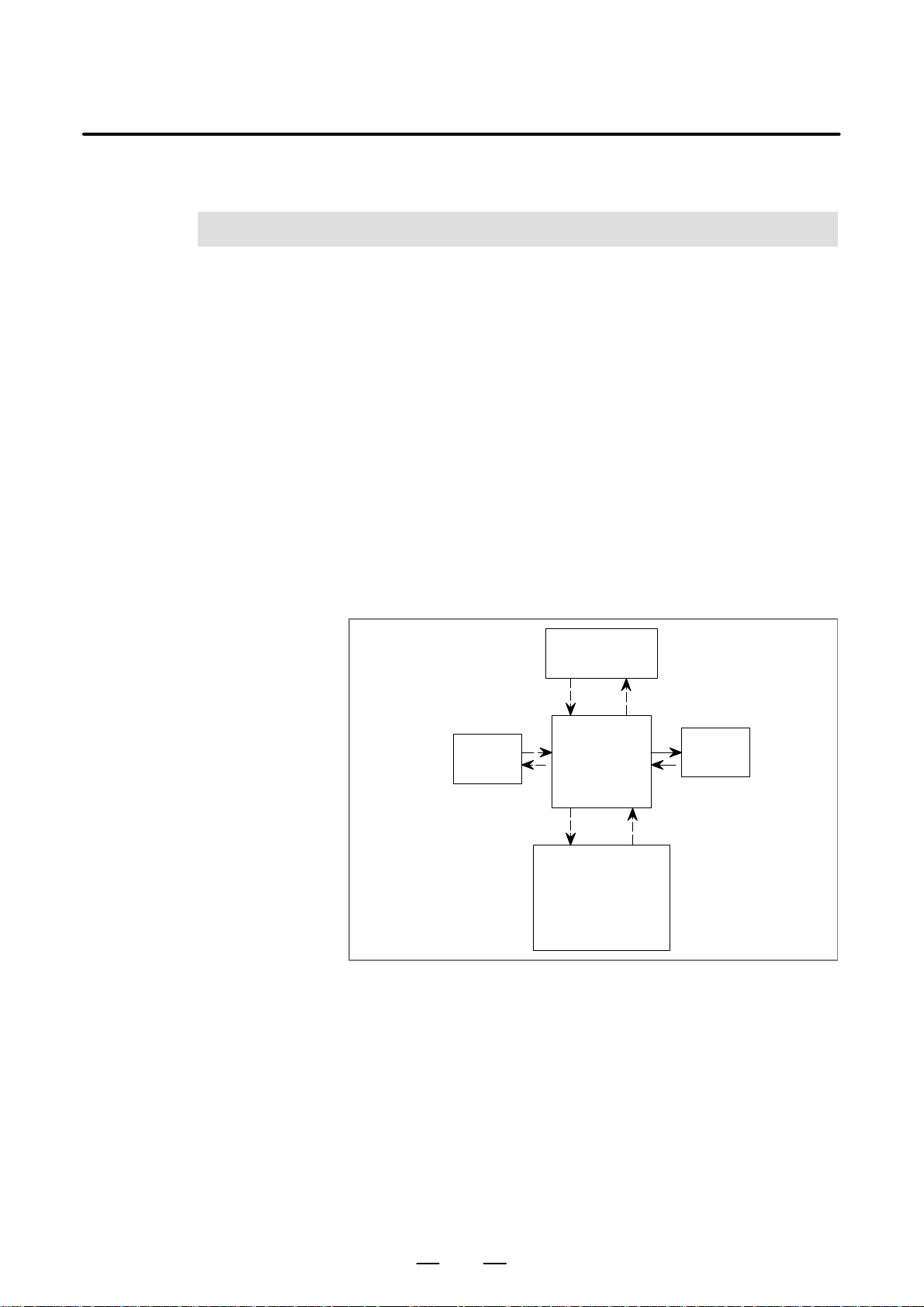
B–61863E/15
3
ADDRESS
PMC SEQUENCE PROGRAM
An address shows a signal location. Addresses include input/output
signals with respect to the machine, the input/output signals with respect
to the CNC, the internal relays, the counters, the keep relays (PMC
parameters), and data table. Each address consists of an address number
(for every 8 signals) and a bit number (0 to 7). Enter the symbol table
showing the relationship between the signal names and the addresses into
the programmer by using the keys of the CRT/MDI or the keys of the
keyboard of the offline programmer as in the case of the sequence
program.
For programming, see Chapter III, IV and V.
(1) Addresses related to PMC
Four types of addresses as shown in Fig. 3 are necessary for creation
of the PMC sequence program.
3. ADDRESS
Internal relay
Note)
(a) The input/output signals with respect to the PMC, which are
indicated by the solid lines, are transferred via the receiver and the
driver of the I/O board.
(b) The input/output signals with respect to the PMC, which are
indicated by the broken lines, are transferred only in the memory
such as the RAM.
All of these signals can be displayed on the CRT/MDI panel.
CNC
signal
Fig. 3 Addresses related to PMC
PMC
Nonvolatile memory
(1) Counter
(2) Keep relay
(3) Data table
(4) Variable Timer
Machine
(MT)
signal
(2) Address regulations
The address comprises the address number and the bit number in the
format as shown below.
61
Page 96
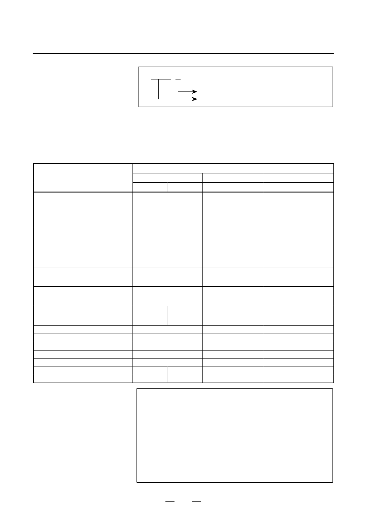
3. ADDRESS
PMC SEQUENCE PROGRAM
B–61863E/15
X 127. 7
Bit number (0 to 7)
Address number (within four numerics after alphabet)
An alphabet must be specified at the beginning of the address number
to indicate the type of the signal as shown in Table 3. When
specifying the address in the byte unit by the functional instruction,
specify X127. In this case, “.” and the bit number are not necessary.
T able 3 Alphabetic characters in address numbers (1)
Model
Character Signal description Power Mate - D Power Mate- F Power Mate- H
PMC PA1 PMC- PA3 PMC- PA3 PMC- PA3
X Signal from the machine to the
PMC (MT to PMC)
Y Signal from the PMC to the
machine (PMC to MT)
(Caution 3)
F Signal from the NC to the PMC
(NC to PMC)
G Signal from the PMC to the NC
(PMC to NC)
R Internal relay (Caution 1) R0 to R999
A Message request signal A0 to A24 A0 to A24 A0 to A24
C Counter C0 to C79 C0 to C79 C0 to C79
K Keep relay (Caution 2) K0 to K19 K0 to K19 K0 to K19
T Variable timer T0 to T79 T0 to T79 T0 to T79
D Data table D0 to D1859 D0 to D1859 D0 to D1859
L Label Number – L1 to L9999 L1 to L9999 L1 to L9999
P Subprogram Number – P1 to P512 P1 to P512 P1 to P512
X0 to X127
(I/O Link Master)
X1000 to X1003
(Built–in l/O Card)
X1020 to X1051
(I/O Link Slave)
Y0 to Y127
(I/O Link Master)
Y1000 to Y1002
(Built–in I/ O Card)
Y1020 to Y1051
(I/O Link Slave)
F0 to F255
F1000 to F1255
(Two–path control)
G0 to G255
G1000 to G1255
(Two–path control)
R9000 to
R9099
R0 to R999
R9000 to
R9117
X1000 to X1005
X1020 to X1027
(Slave)
Y1000 to Y1003
Y1020 to Y1027
(Slave)
F0 to F255 F0 to F255
G0 to G255 G0 to G255
R0 to R999
R9000 to R9117
X0 to X127
X1000 to X1003
X1020 to X1051
Y0 to Y127
Y1000 to Y1002
Y1020 to Y1051
R0 to R999
R9000 to R9117
(I/O Link Master)
(Built–in I/O Card)
(I/O Link Slave)
(I/O Link Master)
(Built–in l/O Card)
(I/O Link Slave)
CAUTION
1 R9000 to R9117 are areas reserved for the PMC system
program; these areas cannot be used for output by a
sequence program.
2 K17 to K19 are areas reserved for the PMC system
program; these areas cannot be used for output by a
sequence program.
3 I/O Link Master function is not available in the Power
Mate–MODEL F.
You cannot use the address X0–127 and Y0–127.
62
Page 97
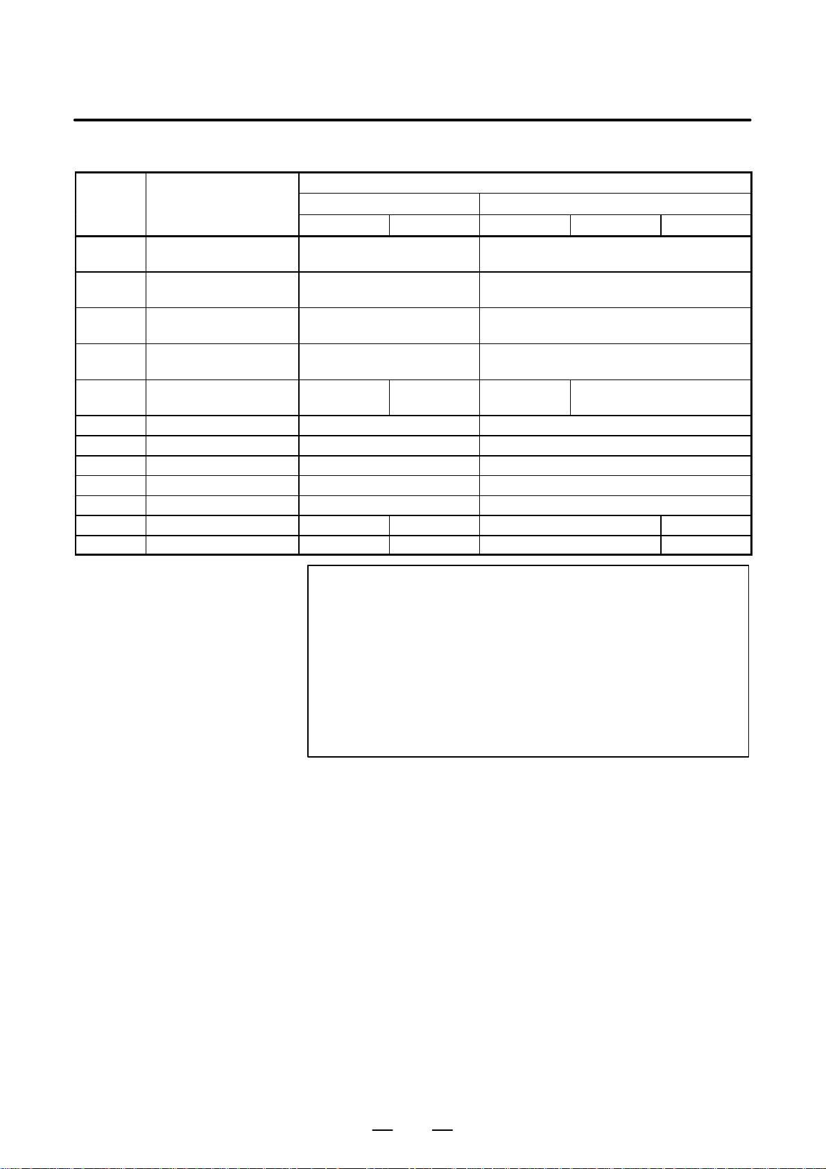
B–61863E/15
PMC SEQUENCE PROGRAM
T able 3 Alphabetic characters in address numbers (2)
Model
Character Signal description FS20A FS18A
PMC-SA1 PMC-SA3 PMC-SA1 PMC-SA2 PMC-SA3
X Signal from the machine to the
PMC (MT to PMC)
Y Ssignal from the PMC to the
machine (PMC to MT)
F Signal from the NC to the PMC
(NC to PMC)
G Signal from the PMC to the NC
(PMC to NC)
R Internal relay (Caution 2) R0 to R999
A Message request signal A0 to A24 A0 to A24
C Counter C0 to C79 C0 to C79
K Keep relay (Caution 3) K0 to K19 K0 to K19
D Data table D0 to D1859 D0 to D1859
T Variable timer T0 to T79 T0 to T79
L Label number – L1 to L9999 – L1 to L9999
P Subprogram number – P1 to P512 – P1 to P512
X0 to X127
X1000 to X1013 (Caution 1)
Y0 to Y127
Y1000 to Y1013 (Caution 1)
F0 to F255
F1000 to F125
G0 to G255
G1000 to G1255
R0 to R999
R9000 to R9099
R9000 to R9117
R0 to R999
R9000 to R9099
X0 to X127
X1000 to X1019
Y0 to Y127
Y1000 to Y1014
F0 to F255
F1000 to F1255
G0 to G255
G1000 to G1255
R0 to R999
R9000 to R9117
3. ADDRESS
CAUTION
1 X1000 to X1007 and Y1000 to Y1007 are configured as a
matrix.
2 R9000 to R9117 are areas reserved for the PMC system
program; these areas cannot be used for output by a
sequence program.
3 K17 to K19 are areas reserved for the PMC system
program; these areas cannot be used for output by a
sequence program.
63
Page 98
3. ADDRESS
Chara–
PMC SEQUENCE PROGRAM
T able 3 Alphabetic characters in address numbers (3)
B–61863E/15
Chara–
cter
X Signal from the machine to the
Y Signal from the PMC to the
F Signal from the NC to the PMC
G Signal from the PMC to the NC
R Internal relay (Caution 1) R0 to R999
A Message request signal A0 to A24
C Counter C0 to C79
K Keep relay (Caution 2) K0 to K19
D Data table D0 to D1859 D0 to D2999
T Variable timer T0 to T79
L Label number – – L1 to L9999 – L1 to L9999
P Subprogram number – – P1 to P512 – P1 to P512
Signal description
PMC (MT to PMC)
machine (PMC to MT)
(NC to PMC)
(PMC to NC)
PMC-SB PMC-SB2 PMC-SB3 PMC-SC PMC-SC3 PMC-NB
R9000 to
R9099
R0 to R999
R9000 to
R9117
R0 to R1499
R9000 to
Model
X0 to X127
X1000 to X1039
Y0 to Y127
Y1000 to Y1029
F0 to F255
F1000 to F1255
G0 to G255
G1000 to G1255
R0 to R1499
R9000 to
R9117
R9099
R0 to R1499
R9000 to
R9117
CAUTION
1 R9000 to R9117 are areas reserved for the PMC system
program; these areas cannot be used for output by a
sequence program.
2 K17 to K19 are areas reserved for the PMC system
program; these areas cannot be used for output by a
sequence program.
X0 to X127
Y0 to Y127
F0 to F319
G0 to G511
R0 to R1499
R9000 to
R9117
64
Page 99

B–61863E/15
PMC SEQUENCE PROGRAM
T able 3 Alphabetic characters in address numbers (4)
Model
Character
Signal descrip-
tion
Series 16-MODEL B/Series 18-MODEL B
PMC-SB3 PMC-SC3 PMC-SB4 PMC-SC4 PMC-SA1
X Signal from the
machine to the PMC
(MT to PMC)
Y Signal from the PMC
to the machine (PMC
to MT)
F Signal from the NC to
the PMC (NC to
PMC)
G Signal from the PMC
to the NC (PMC to
NC)
R Internal relay R0 to R1499
A Message request
signal
C Counter C0 to C79 C0 to C199 C0 to C79
K Keep relay K0 to K19 K0 to K39
T Data table T0 to T79 T0 to T299 T0 to T79
D Variable timer D0 to D2999 D0 to D7999 D0 to D1859
L Label number L1 to L9999 L1 to L9999 –
P Subprogram number P1 to P512 P1 to P2000 –
F0 to F255
F1000 to F1255
G0 to G255
G1000 to G1255
R9000 to R9117
A0 to A24 A0 to A124 A0 to A24
X0 to X127
X1000 to X1019
X1020 to X1039
Y0 to Y127
Y1000 to Y1014
Y1020 to Y1034
F0 to F511
F1000 to F1511
F2000 to F2511
G0 to G511
G1000 to G1511
G2000 to G2511
R0 to R2999
R9000 to R9199
K900 to K909
3. ADDRESS
Series
18-MODEL B
F0 to F255
F1000 to F1255
G0 to G255
G1000 to G1255
R0 to R999
R9000 to R9099
K0 to K19
65
Page 100

3. ADDRESS
PMC SEQUENCE PROGRAM
T able 3 Alphabetic characters in address numbers (5)
Model
Character Signal description Series 16-MODEL C/Series 18-MODEL C
PMC-SB5 PMC-SC3 PMC-SB6 PMC-SC4
X Signal from the machine to the PMC (MT to
PMC)
Y Signal from the PMC to the machine (PMC
to MT)
F Signal from the NC to the PMC (NC to
PMC)
G Signal from the PMC to the NC (PMC to
NC)
R Internal relay R0 to R1499
A Message request signal A0 to A24 A0 to A124
C Counter C0 to C79 C0 to C199
K Keep relay K0 to K19 K0 to K39
T Data table T0 to T79 T0 to T299
D Variable timer D0 to D2999 D0 to D7999
L Label number L1 to L9999 L1 to L9999
P Subprogram number P1 to P512 P1 to P2000
F0 to F255
F1000 to F1255
G0 to G255
G1000 to G1255
R9000 to R9117
X0 to X127
X1000 to X1019
X1020 to X1039
Y0 to Y127
Y1000 to Y1014
Y1020 to Y1034
F0 to F511
F1000 to F1511
F2000 to F2511
G0 to G511
G1000 to G1511
G2000 to G2511
R0 to R2999
R9000 to R9199
K900 to K909
B–61863E/15
66
 Loading...