

Page 1
CONT
CS 7.5 S6
Page 2

Page 3
CONT
Operator's Manual
CS 7.5 S6
Page 4

Publication:
31.0078.E0
08/2006
Page 5

Introduction
SECTION 1
General Information
SECTION 2
General Safety
Operator’s Manual
Index
INDEX
SECTION 3
Groundcrew Safety Guidelines
SECTION 4
Operator’s Controls
SECTION 5
Operating Procedures
SECTION 6
Warranty
SMT.IND04.E01
I - 1 OI00.0001
Page 6

Operator’s Manual
Index
NOTES
I - 2 OI00.0001
Page 7

Operator's Manual
Introduction
OPERATOR'S MANUAL
FOREWORD
USE OF THE MANUAL
This document is the “Operation & Maintenance Manual”.
It is an essential part of the supply and shall be properly kept and always made
available to the staff involved in operation and maintenance activities.
The text is written with the aim to help the staff involved in operation and maintenance
activities and contains instructions, information and all necessary recommendations
for keeping the truck in safe and efficient conditions.
Before the truck is put into service, the User is required to read all the sections of this
manual carefully, to ensure that it also read by all the persons assigned to the
operation or maintenance of the truck, and to ensure that it is always readily available
for reference.
It should be made clear that no machine can withstand misuse and negligence,
therefore it is recommended that the instructions described in this manual be strictly
followed.
In order to make the maintenance section more fluent, some basic concepts have
been omitted, that should be familiar to people having average experience on the
matter.
This manual is based on the state of technology at the time of truck sale, therefore
it cannot be considered inadequate on the basis of more recent technical knowledge
and solutions at the moment of truck commissioning.
This manual is the property of Fantuzzi-Reggiane S.p.A. and may not be reproduced
totally or partially nor may it be transmitted to a third party without the written
permission of Fantuzzi-Reggiane S.p.A.
The manual and the relevant technical documentation complies with European
Standards and Codes on machines, according to directive 98/37/CE.
OP00.0011 i - 1
Page 8
Operator's Manual
SYMBOLS USED IN THE MANUAL
Danger: generic
Danger: high voltage
Danger: suspended loads
SMT.0532.E00
Introduction
SIGN PLATES
SMT.0010.E01
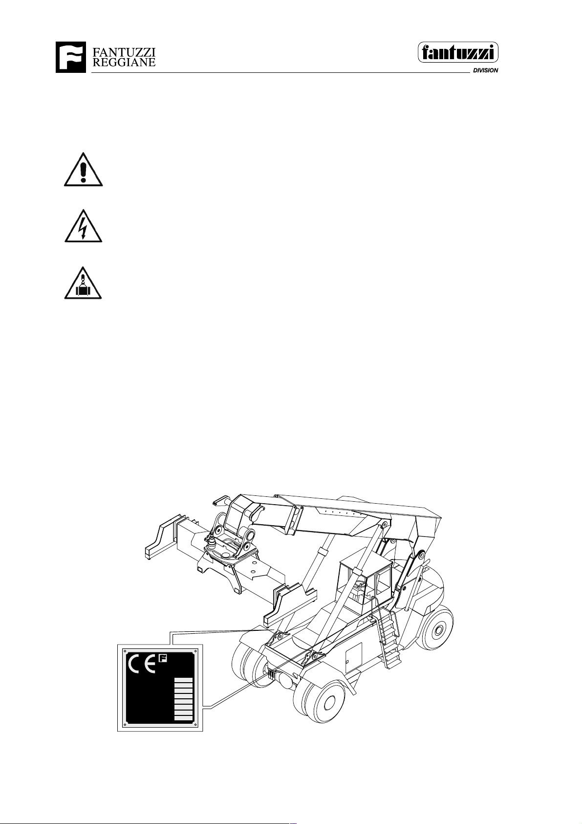
The equipment is identifiable by means of printed plates which are found along the
left sides of the equipment.
The plate with CE sign guarantee that the machine is manufactured in compliance
with the Directives 98/37 CE.
The type of equipment and the factory number are the means of reference for any
communication between the user and Fantuzzi-Reggiane SpA.
SMT.0010.E01
FANTUZZI
REGGIANE
FANTUZZI DIVISION
Via Cisa Ligure, 51/A 42040 Lentigione (RE) Italy
Tel.+39(0)522.96744-Fax +39(0)522.680426
MODELLO
N° DI MATRICOLA
ANNO DI COSTRUZIONE
PESO A VUOTO CON ATTREZZATURA
PNEUMATICI
PRESSIONE PNEUMATICI
CAPACITA' MASSIMA Kg
ANTERIORI
(BAR)
POSTERIORI
(BAR)
Kg
1986
i - 2 OP00.0011
Page 9

Operator's Manual
Introduction
GENERAL INFORMATION
GENERAL SAFETY PRECAUTIONS
- Make sure you are perfectly acquainted with the position and function of each
control and try the truck out on a safe area free of obstacles and persons. Do not
allow unauthorised personnel to use the truck.
- Use the steps to enter and exit the truck, using the handrail, two hands and keeping
the front part of the body turned towards the machine.
- Do not get in and out of the truck while this is moving.
- Do not jump out of the truck; Do not apply pressure on the controls or hoses. Wear
a helmet, goggles, and safety clothing and footwear, in accordance with applicable
regulations.
- Keep the platforms, hoods, cab and footwear free of oil, diesel fuel and grease to
prevent slipping. Do not walk on edges, pipes or surfaces that could give way.
- Read and understand all the hazard notices and precautions to be taken as
indicated on the panels on the truck.
- The machine operator or maintenance engineer shall be responsible for replacing
any deteriorated notice which is no longer readable or missing notice, especially
those relating to safety. The position of such notices with relevant codes is shown
in the spare parts catalogue.
Fantuzzi-Reggiane S.p.A. cannot accepts any liability for any injury or damage
arising from:
• improper use;
• use by untrained personnel;
• lack of maintenance;
• use of non-original replacement parts;
• total or partial failure to comply with the instructions;
• tampering with the safety devices and safeguards;
• exceptional events;
• use of products other than those indicated;
• unauthorised modifications.
OP00.0011 i - 3
Page 10

Operator's Manual
Introduction
Instructions for truck operation and use
• The truck shall be operated by appointed personnel only.
• Never hoist a load heavier than those indicated on the chart.
• Do not allow unauthorised people to stand within the truck operating radius.
• Do not leave the operating station with a suspended load.
• Check efficiency of brakes and safety devices.
• Ensure that the stabilisers are fully extended and positioned on a solid surface.
WARNING NOTICES
It is the User’s responsibility to ensure that all the required notices are present and
are legible from the positions occupied by the persons to whom they are addressed.
Replace any notices that are illegible or have been removed: replacement notices
should be ordered from Fantuzzi-Reggiane S.p.A. before the original notices become
illegible.
Fantuzzi-Reggiane S.p.A. cannot accept any liability for any damage/injury sustained
as a result of the user’s failure to order replacement notices in due time.
PERSONNEL TRAINING
All personnel assigned to operations on the truck must:
• be competent of carrying out the work to which they are assigned;
• have received adequate instruction on the specific operations to which they are
assigned;
• have fully understood all instructions;
• be aware of all potential hazards;
• have sufficient specific knowledge to understand all the instructions and technical
standards, with particular regard to accident prevention;
• have no physical handicaps or defects such as to render them unable to carry out
correctly all the operations to which they are assigned and be unable to access the
machine without limitations.
• Wear a hard hat, eye protection, safety clothing and footwear in accordance with
applicable safety regulations.
i - 4 OP00.0011
Page 11

Operator's Manual
Introduction
OPERATOR’S RESPONSIBILITIES
Safety must always be the first priority of the operator.
He must always refrain from operating the truck on detecting any condition which
might jeopardise safety, inform his superior and take suitable action to remove the
cause of the condition.
He must know how to consult the load capacities chart and, before attempting to lift
each load, he must be certain that the truck can lift it safely.
He must be alert, physically fit and must not be under the influence of alcohol, drugs
or medication which could affect his eyesight, hearing or reflexes.
When visibility does not allow optimum control of the operations, or when working in
hazardous areas (presence of electric lines, pipes, people, etc.), the operator must
deploy a signaller.
The operator must only follow the signals given by the designated signaller.
The operator must, however, at all times obey any signal to stop given by anyone
working on the site.
WARRANTY
Fantuzzi-Reggiane S.p.A. guarantees the machine against defects, as well as the
materials supplied and their putting into service and calibration in accordance with
the time schedule and methods agreed at the time of purchase.
The warranty does not cover damage sustained as a result of accidental breakage,
tampering, negligence and carelessness on the part of the User, or unauthorised
modifications to the machine or any operations prohibited by this manual.
AFTER-SALES SERVICE
The User is required to inform Fantuzzi-Reggiane S.p.A. and receive approval prior
to replacing any parts or carrying out any modifications.
We recommend that only original replacement parts are used.
Fantuzzi-Reggiane S.p.A. is always available for assistance, routine or major
servicing, advice on maintenance of the truck and for clarification of any of the
information contained in or omitted from this manual.
OP00.0011 i - 5
Page 12

Operator's Manual
Introduction
DISMANTLING AND SCRAPPING THE TRUCK
As the truck is a complex machine with some very large and heavy components,
dismantling and scrapping should only be entrusted to specialised personnel.
We therefore recommend to contact Fantuzzi-Reggiane S.p.A. for assistance in
dismantling operations.
PRODUCT DISPOSAL
All products used during the course of maintenance, repair and part replacement
operations (e.g. oil, grease, batteries) are to be disposed of in accordance with the
specific legal requirements for each type of product.
FIRST AID
Call a doctor immediately in all cases of serious injury.
After administering first aid, send the patient to a doctor.
Never attempt any medical procedures of which you are unsure as this could harm
the patient.
Remove the patient from the harmful environment.
Put the patient in the best possible conditions for rest; loosen clothing, collar, belt
and, if necessary, cover with a blanket
Never give any drink to someone who is unconscious.
Before touching any wounds, wash your hands with soap and water and, if possible,
disinfect them.
Disinfect any wounds, if you know how to do this correctly. Otherwise, cover with
sterile gauze and apply pressure with a cotton wool wad impregnated with alcohol
and a tight bandage.
In the case of heavy bleeding from an arm or leg, apply a tourniquet above the wound
and take the patient to the nearest accident unit.
SMT.0533.E00
i - 6 OP00.0011
Page 13
Operator's Manual
Section 1 - General Information
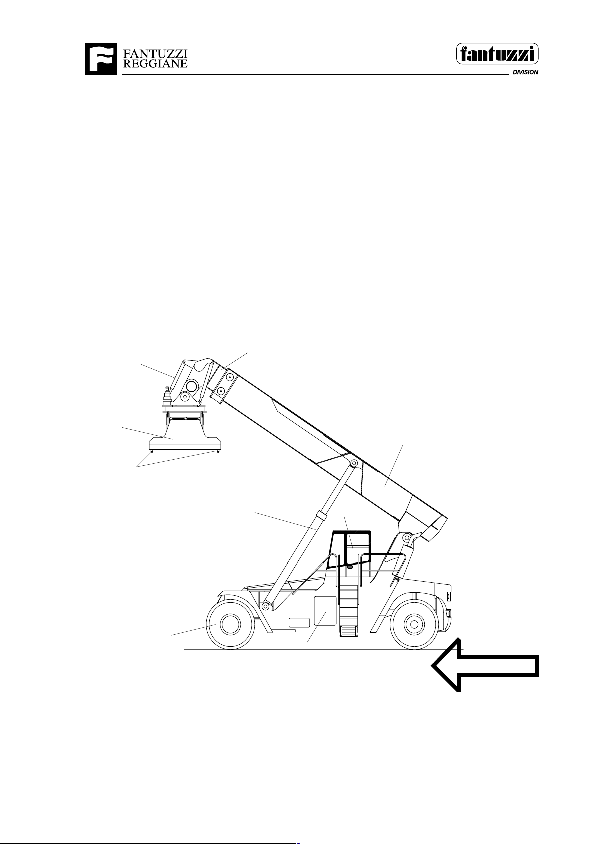
GENERAL DESCRIPTION AND POSITIONING
The arm truck is suitable for lifting heavy loads and is used for the combined transport
of containers- from railway wagons to road vehicles.
1. Rear wheels (steering)
2. Electrical compartment
3. Front wheels (drive)
4. Lifting cylinder
5. Operator cab
6. Fixed arm
7. Moving arm
8. Damping cylinder
9. Spreader
10.Twistlocks
SMT.0527.E
9
8
10
7
6
4
3
2
5
1
1994
FRONT
IMPORTANT: The machine’s orientation (Front, Rear, Left, Right) as referenced in
this manual is based on the operator’s perspective when seated. SMT.0199.E00
OP01.0024 1 - 1
Page 14
Operator's Manual
Section 1 - General Information
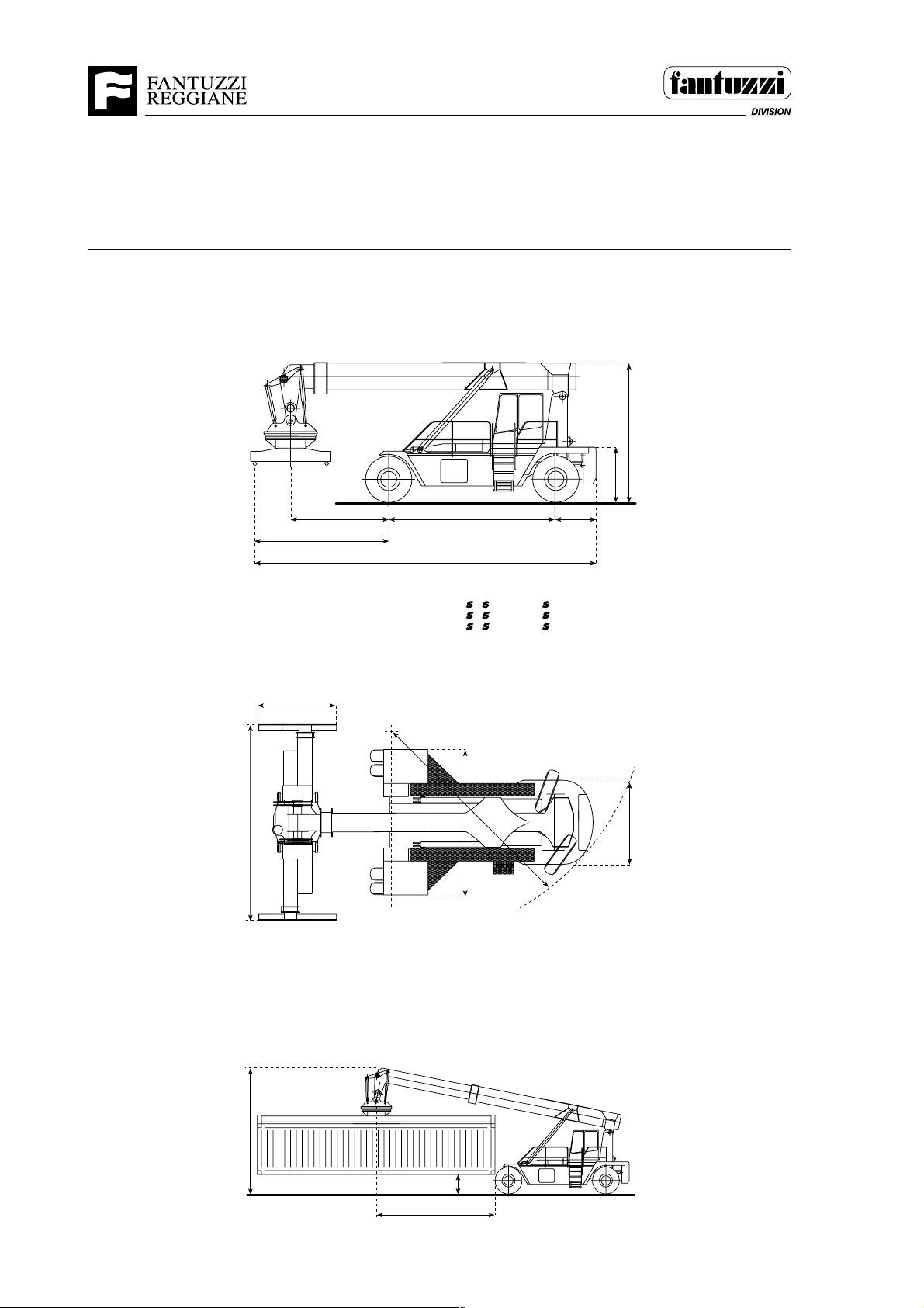
DIMENSIONS CS 7.5 S5 - S6 - S7
(in mm.)
4100
1500
6050
2440
b
c
5000
d
b) S5-S7 = 2800 S6 = 3800
c) S5-S7 = 4025 S6 = 5025
d) S5-S7 = 10225 S6 = 11225
4500
R=6900
1200
2500
6700
4,5
1000
6100
2053
1 - 2 OP01.0024
Page 15
Operator's Manual
Section 1 - General Information
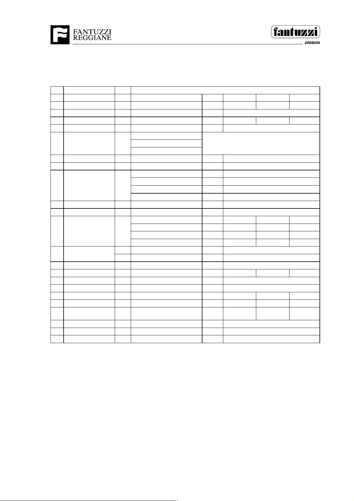
TECHNICAL SPECIFICATIONS CS 7.5 S5 - S6 - S7
1rerutcafunaM IZZUTNAF
2ledoMEPYT 5S5.7SC6S5.7SC7S5.7SC
3ytpmethgieW .gK005730009300014
4noisluporPsaG,lorteP,leseiD,lacirtcelE leseiD
5seryTseryT=L-erytdiloS=VR/FL/LL/LL/L
6)evird=x(sleehWrebmuNR/F2/4
mrA
7slairetaM
8esioNbacnI/edistuO)A(Bd67/58
9ecnamrofrePdedaol/ytpmedeepSh/mk32/52
01redaerpS
11gnireetSdetsissa-ovreS-ciluardyH
elxaevirD sraegnoitcudercilcycipehtiW
21seryT
31sekarbecivreS
ekarbgnikraPesaelerlacinahceM noissimsnartnocsidyrD
41yrettaByticapac/egatloVhA/V051/42051/42051/42
51rotoM elbaTrotoMeeS
61noissimsnarT retrevnoceuqrothtiwcimanydordyH
71hctulC tfihS-rewoPtfihS-rewoPtfihS-rewoP
81rotcelesraeGesreveR/drawroF.oN4/44/44/4
91
metsys
02slortnoC detsissa-ovres
12yticapacknaTdiulfciluardyHsertil066
gniloocciluardyH
tnorF htabliocsiD
raeRlanoitpO yrdcsiD
sissahC
redaerpS
'04-'02epytcipocseleT 01RS
noitatoRseerged°581+/°59-
tfihsediS.mm008+/008-
noitallicsolaretaLseerged°3-/+
raer/tnorfrebmuN2/42/4
tnorfnoeziS42-00.4142-00.4142-00.41
raernoeziS42-00.4142-00.4142-00.41
erusserpnoitalfnIrab010101
seYseYseY
leuFsertil033
007xodleW
)25eF(D015eF
D015eF/007xodleW
1934/E
OP01.0024 1 - 3
Page 16
Section 1 - General Information
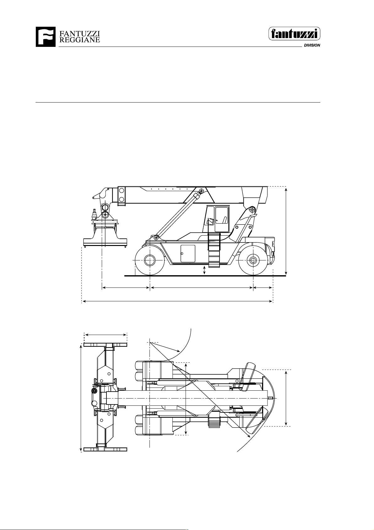
DIMENSIONS CS 42 - 45 KC
DIMENSIONS in mm
Operator's Manual
(in mm.)
2440
10920
1050
5200
500
57502700
1250
6050
1 - 4 OP01.0024
4200
R= 7800
3300
1926
Page 17
Operator's Manual
Section 1 - General Information
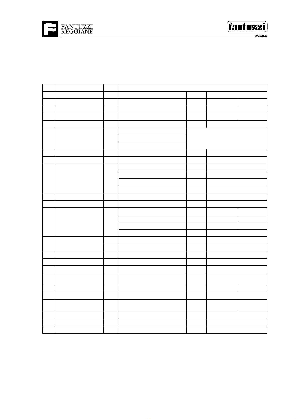
TECHNICAL SPECIFICATIONS CS 42 - 45 KC
1rerutcafunaM IZZUTNAF
2ledoMEPYT cK24SCcK54SC
3ytpmethgieW .gK0008600596
4noisluporPsaG,lorteP,leseiD,lacirtcelEleseiD
5seryTseryT=L-erytdiloS=VR/FL/LL/L
6)evird=x(sleehWrebmuNR/F2/4
mrA
7slairetaM
8esioNbacnI/edistuO)A(Bd47/58
9ecnamrofrePdedaol/ytpmedeepSh/mk32/52
01redaerpS
11gnireetSdetsissa-ovreS-ciluardyH
elxaevirD sraegnoitcudercilcycipehtiW
21seryT
31sekarbecivreS
ekarbgnikraPesaelerlacinahceM noissimsnartnocsidyrD
41yrettaByticapac/egatloVhA/V002/42002/42
51rotoM elbaTrotoMeeS
61noissimsnarT
71hctulC tfihS-rewoPtfihS-rewoP
81rotcelesraeGesreveR/drawroF.oN4/44/4
91
02slortnoC detsissa-ovres
12yticapacknaTdiulfciluardyHsertil059
metsys
gniloocciluardyH
tnorF htabliocsiD
raeRlanoitpOyrdcsiD
sissahC
redaerpS
'04-'02epytcipocseleT54PRS
noitatoRseerged°581+/°59-
tfihsediS.mm008+/008-
noitallicsolaretaLseerged°3-/+
raer/tnorfrebmuN2/42/4
tnorfnoeziS52-00.8152-00.81
raernoeziS52-00.8152-00.81
erusserpnoitalfnIrab0101
leuF064
007xodleW
seYseY
)25eF(D015eF
D015eF/007xodleW
euqrothtiwcimanydordyH
retrevnoc
1933/E
OP01.0024 1 - 5
Page 18
Section 1 - General Information
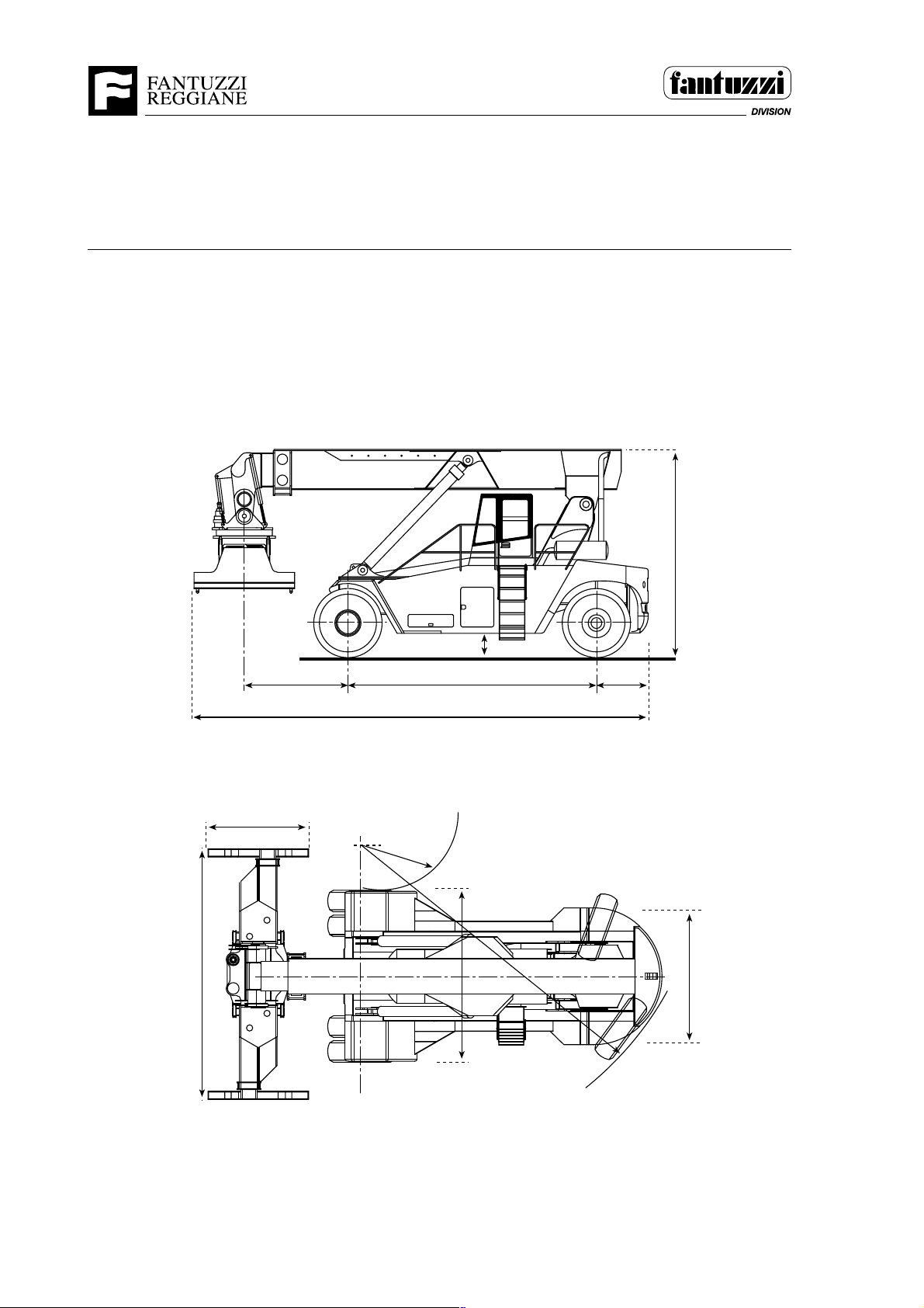
DIMENSIONS CS 42 - 45 KM
DIMENSIONS in mm
Operator's Manual
(in mm.)
6050
2440
2900
11370
1050
500
6000
4200
5100
1250
3300
R=
8000
2055
1 - 6 OP01.0024
Page 19
Operator's Manual
Section 1 - General Information
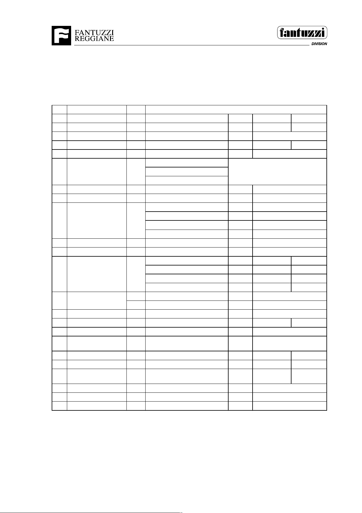
TECHNICAL SPECIFICATIONS CS 42 - 45 KM
1rerutcafunaM IZZUTNAF
2ledoMEPYT mK24SCmK54SC
3ytpmethgieW .gK0000700027
4noisluporPsaG,lorteP,leseiD,lacirtcelEleseiD
5seryTseryT=L-erytdiloS=VR/FL/LL/L
6)evird=x(sleehWrebmuNR/F2/4
mrA
7slairetaM
8esioNbacnI/edistuO)A(Bd47/58
9ecnamrofrePdedaol/ytpmedeepSh/mk32/52
01redaerpS
11gnireetSdetsissa-ovreS-ciluardyH
elxaevirD sraegnoitcudercilcycipehtiW
21seryT
31sekarbecivreS
ekarbgnikraPesaelerlacinahceM noissimsnartnocsidyrD
41yrettaByticapac/egatloVhA/V002/42002/42
51rotoM elbaTrotoMeeS
61noissimsnarT
71hctulC tfihS-rewoPtfihS-rewoP
81rotcelesraeGesreveR/drawroF.oN4/44/4
91
02slortnoC detsissa-ovres
12yticapacknaTdiulfciluardyHsertil058
metsys
gniloocciluardyH
tnorF htabliocsiD
raeRlanoitpOyrdcsiD
sissahC
redaerpS
'04-'02epytcipocseleT54PRS
noitatoRseerged°581+/°59-
tfihsediS.mm008+/008-
noitallicsolaretaLseerged°3-/+
raer/tnorfrebmuN2/42/4
tnorfnoeziS52-00.8152-00.81
raernoeziS52-00.8152-00.81
erusserpnoitalfnIrab0101
leuF005
007xodleW
seYseY
)25eF(D015eF
D015eF/007xodleW
euqrothtiwcimanydordyH
retrevnoc
1932/E
OP01.0024 1 - 7
Page 20
Section 1 - General Information
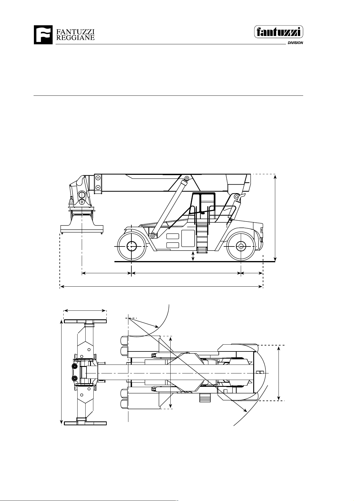
DIMENSIONS CS 45 KL - 45 KS
DIMENSIONS in mm
Operator's Manual
(in mm.)
6050
2440
1050
11570
4200
5000
500
62502850
1250
3300
R=
8100
2056
1 - 8 OP01.0024
Page 21
Operator's Manual
Section 1 - General Information
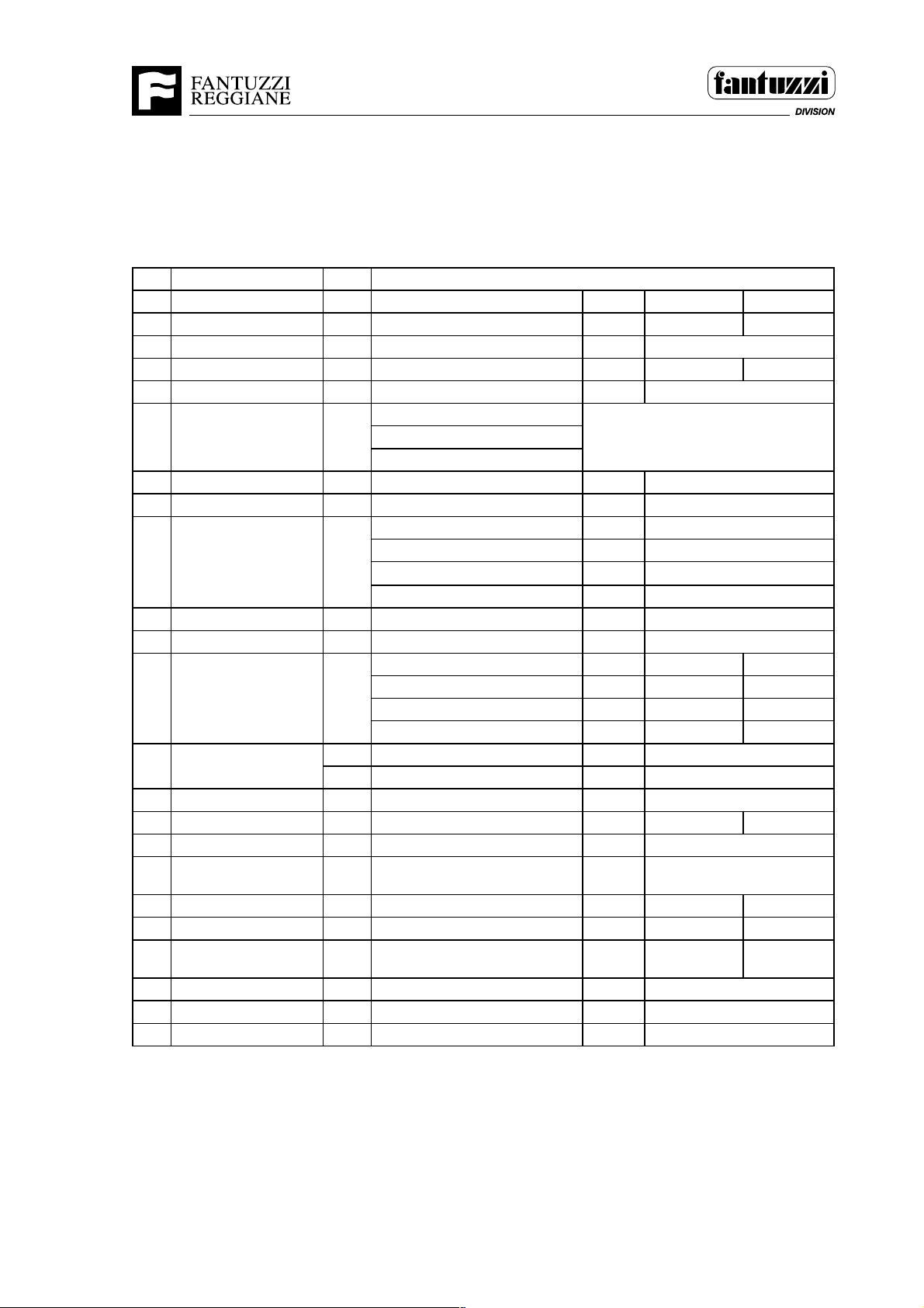
TECHNICAL SPECIFICATIONS CS 45 KL - KS
1rerutcafunaM IZZUTNAF
2ledoMEPYT LK24SCSK54SC
3ytpmethgieW .gK0001700057
4noisluporPsaG,lorteP,leseiD,lacirtcelEleseiD
5seryTseryT=L-erytdiloS=VR/FL/LL/L
6)evird=x(sleehWrebmuNR/F2/4
mrA
7slairetaM
8esioNbacnI/edistuO)A(Bd47/58
9ecnamrofrePdedaol/ytpmedeepSh/mk32/52
01redaerpS
11gnireetSdetsissa-ovreS-ciluardyH
elxaevirD sraegnoitcudercilcycipehtiW
21seryT
31sekarbecivreS
ekarbgnikraPesaelerlacinahceM noissimsnartnocsidyrD
41yrettaByticapac/egatloVhA/V002/42002/42
51rotoM elbaTrotoMeeS
61noissimsnarT
71hctulC tfihS-rewoPtfihS-rewoP
81rotcelesraeGesreveR/drawroF.oN4/44/4
91
02slortnoC detsissa-ovres
12yticapacknaTdiulfciluardyHsertil0001
metsys
gniloocciluardyH
tnorF htabliocsiD
raeRlanoitpOyrdcsiD
sissahC
redaerpS
'04-'02epytcipocseleT54PRS
noitatoRseerged°581+/°59-
tfihsediS.mm008+/008-
noitallicsolaretaLseerged°3-/+
raer/tnorfrebmuN2/42/4
tnorfnoeziS52-00.8152-00.81
raernoeziS52-00.8152-00.81
erusserpnoitalfnIrab0101
leuF055
007xodleW
seYseY
)25eF(D015eF
D015eF/007xodleW
euqrothtiwcimanydordyH
retrevnoc
1931/E
OP01.0024 1 - 9
Page 22
Operator's Manual
Section 1 - General Information
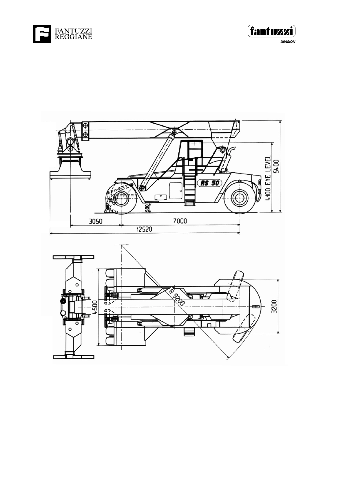
DIMENSIONS RS 50
1974
1 - 10 OP01.0024
Page 23
Operator's Manual
Section 1 - General Information
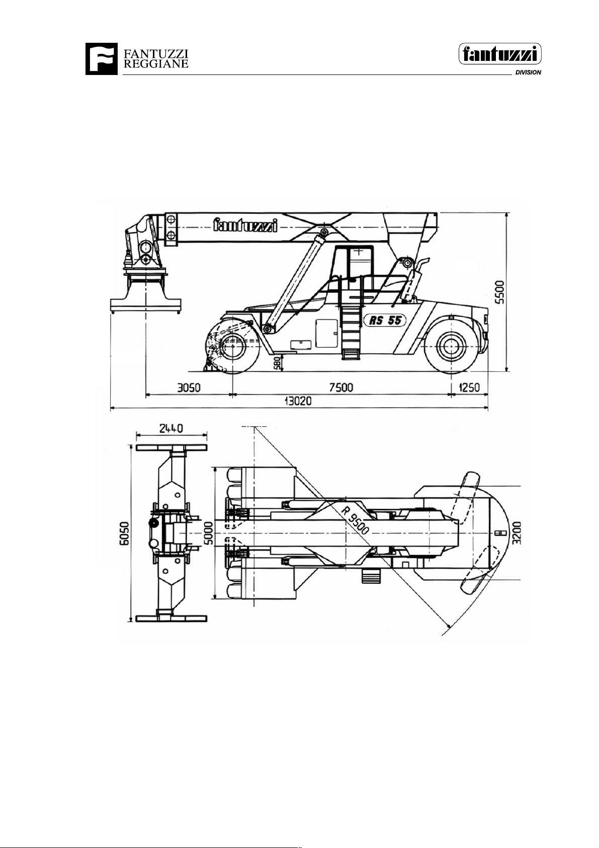
DIMENSIONS RS 55
1976
OP01.0024 1 - 11
Page 24
Operator's Manual
Section 1 - General Information
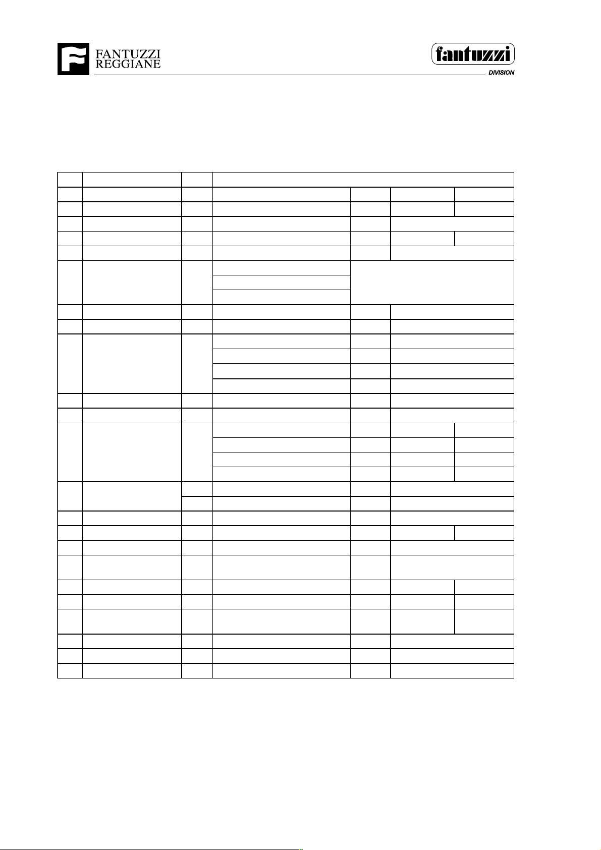
TECHNICAL SPECIFICATIONS RS 50 - 55
1rerutcafunaM IZZUTNAF
2ledoMEPYT 05SR55SR
3ytpmethgieW .gK0005800068
4noisluporPsaG,lorteP,leseiD,lacirtcelEleseiD
5seryTseryT=L-erytdiloS=VR/FL/LL/L
6)evird=x(sleehWrebmuNR/F2/4
mrA
7slairetaM
8esioNbacnI/edistuO)A(Bd47/58
9ecnamrofrePdedaol/ytpmedeepSh/mk32/52
01redaerpS
11gnireetSdetsissa-ovreS-ciluardyH
elxaevirD sraegnoitcudercilcycipehtiW
21seryT
31sekarbecivreS
ekarbgnikraPesaelerlacinahceM noissimsnartnocsidyrD
41yrettaByticapac/egatloVhA/V002/42002/42
51rotoM elbaTrotoMeeS
61noissimsnarT
71hctulC tfihS-rewoPtfihS-rewoP
81rotcelesraeGesreveR/drawroF.oN4/44/4
91
02slortnoC detsissa-ovres
12yticapacknaTdiulfciluardyHsertil0001
metsys
gniloocciluardyH
tnorF htabliocsiD
raeRlanoitpOyrdcsiD
sissahC
redaerpS
'04-'02epytcipocseleT54PRS
noitatoRseerged°581+/°59-
tfihsediS.mm008+/008-
noitallicsolaretaLseerged°3-/+
raer/tnorfrebmuN2/42/4
tnorfnoeziS33-00.8133-00.81
raernoeziS33-00.8133-00.81
erusserpnoitalfnIrab0101
leuF055
007xodleW
seYseY
)25eF(D015eF
D015eF/007xodleW
euqrothtiwcimanydordyH
retrevnoc
1988/E
1 - 12 OP01.0024
Page 25
Operator's Manual
Section 1 - General Information
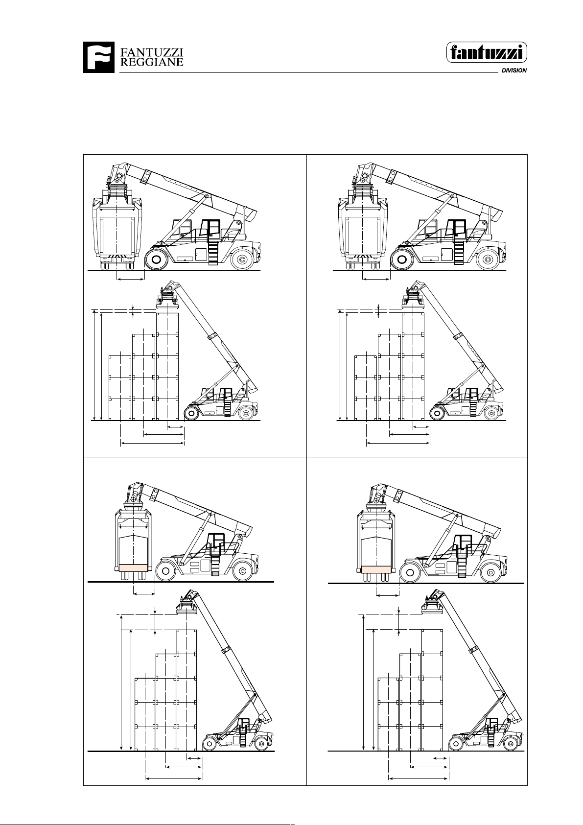
LIFTING CAPACITY IN TONNES OF THE CONSTACKERS
FEATURING PIGGY-BACK SPREADER
(Dimensions in mm.)
CS 42 KM
CS 45 KM
14950
5 x 9'6"
45
1700
9
9
9
450
24
24
24
24 42
6350
27
42
42
42
1900÷1450
3850
CS 45 KL
14950
5 x 9'6"
45
1700
450
24
9
24
9
24
9
24 42
6350
CS 45 KS
27
42
42
42
1900÷1450
3850
45
1700
1600
40
27 45
11
27
27
27
6350
3850
45
45
45
2000÷1330
14600
5 x 8'6"
11
11
OP01.0024 1 - 13
14600
45
5 x 8'6"
1700
14
14
14
1600
31 45
31
31
31
6350
3850
40
45
45
45
2000÷1330
1929
Page 26

Operator's Manual
Section 1 - General Information
MOTOR TABLE
epyT/rerutcafunaMrewoP.veR.rNrednilycfo.rNmc(tnemecalpsiD
EV027DATOVLOVpH732-Wk471000260517
EV137DWTovloVpH832004260376
EV1301DWTovloVpH023001260069
EV1321DWTovloVpH00400126 00021
EV0421DWTovloVpH84300126 00121
C-11MsnimmuCpH03300126 00801
41NSNIMMUCpH00400126 00041
3
)
B6033rallipretaCpH54200226 00501
B6033rallipretaCpH00300226 00501
1930/E
1 - 14 OP01.0024
Page 27
Operator's Manual
Section 1 - General Information
IMPORTANT NOTICE REGARDING BRAKING
SMT.0014.E00
A variable distance is required to stop the machine, depending on the load and
speed.
Although it may be possible to stop an automobile traveling at 5 M.P.H. (8 K.P.H.) in
just a few feet, a train traveling at the same speed requires a much greater distance
to stop because of its additional weight and inertia. Likewise, a machine also requires
a greater stopping distance. The machine’s inertial force results from its speed and
weight. This force will influence how quickly a machine can be stopped just like any
other vehicle. Because of the machine’s gross weight, it cannot be stopped instantly.
Seeing that the machine cannot be stopped instantly be sure to allow ample
stopping distance when driving to avoid collisions.
SMT.0014.E00
WARNING
Working in the area of industrial equipment is dangerous. Personnel in the area of
industrial machines are subject to certain hazards that cannot be met by mechanical
means but only by the exercise of intelligence, care, and common sense. It is
therefore essential to have personnel involved in the use and operation of equipment
who are competent, careful, physically and mentally qualified, and trained in the safe
operation of the equipment and the handling of loads. SMT.0013.E00
OP01.0024 1 - 15
Page 28

Operator's Manual
Section 1 - General Information
1 - 16 OP01.0024
Page 29

Operator's Manual
Section 2 - General safety
SECTION 2 • GENERAL SAFETY
GENERAL INFORMATION
SMT.0016.E00
Your safety and the safety of others in the work area of the machine is a direct result of
your correct operation of this machine.
Know the location, positions and functions of all the controls. Make sure you check all
controls in a safe, clear area before you work the machine.
Read this manual completely and make sure you understand the contents. Make sure
you understand, for example, the characteristics of speed, stability, brakes, steering,
etc., of this machine.
If you have any questions, contact Service Assistance department FANTUZZI-REGGIANE
Spa.
Always keep this manual with your machine. It is recommended that you make copies
of the safety guidelines in this manual and put these copies in the work area.
If this manual is lost or the signs one the machine deteriorate the operator should ask
for a replacement from the manufacturer. FANTUZZI-REGGIANE Spa will not be held
resposible for any damage caused due to any delays in requesting a substitute copy.
SMT.0016.E00
LOCAL LAWS
SMT.0017.E00
The safety information in this manual does not replace any other rules or laws for safety
that are used in your area. Know the local rules or laws for safety. Make sure that your
machine has the correct equipment to operate according to these rules or laws.
SMT.0017.E00
USING COMMON SENSE
SMT.0018.E00
All safety hazards that can possibly arise cannot be foreseen and noted in this manual.
You must always use common sense and apply the general as well as the specific safety
precautions.
SMT.0018.E00
OP02.0012 2 - 1
Page 30
Operator's Manual
Section 2 - General safety
TERMINOLOGY
SMT.0019.E00
The following terms define the various precautions and notices used in this manual.
NOTE
“NOTE” is the term used whenever information requires additional emphasis beyond the standard text.
IMPORTANT
“IMPORTANT” is the term used whenever information requires special attention to procedures to ensure
proper operation or to prevent possible equipment failure.
CAUTION
“CAUTION” is the term used whenever there is potential for equipment damage that requires correct
procedures/practices for prevention.
WARNING
“WARNING” is the term used whenever there is a potential for personal injury or death that requires correct
procedures/practices for prevention.
DANGER
“DANGER” is the term used whenever there is an immediate hazard that cannot be eliminated by design
safeguards, which could result in personal injury or death.
SMT.0019.E00
WARNING
Working in the area of industrial equipment is dangerous. Personnel
in the area of industrial machines are subject to certain hazards that
cannot be met by mechanical means but only by the exercise of
intelligence, care, and common sense. It is therefore essential to have
personnel involved in the use and operation of equipment who are
competent, careful, physically and mentally qualified, and trained in
the safe operation of the equipment and the handling of loads.
SMT.0020.E00
2 - 2 OP02.0012
Page 31
Operator's Manual
Section 2 - General safety
SAFETY RESPONSIBILITY OF THE OPERATOR
SMT.0021.E00
The safety instructions and warnings in this manual, which is shipped with the machine,
provide the most reliable procedures for the safe operation of the machine. It is your
responsibility to see that they are carried out.
Remember, YOU are the person in control of the machine. Do not move it until YOU know
it is safe to do so.
WARNING
Do not move the machine until the surrounding area has been checked
and is clear of personnel and obstructions.
WARNING
Electrical, mechanical, and hydraulic safety devices have been installed
on this machine to help protect against personal injury and/or damage to
equipment. Under no circumstances should any attempt be made to
disconnect or in any way render any of these devices inoperative. If a
malfunction of any safety device is discovered to exist, DO NOT operate
the machine, immediately notify appropriate maintenance personnel.
SMT.0023.E00
SMT.0022.E00
Proper lighting, safety signs, warning bells, etc., can only ASSIST in preventing an
accident. But YOU, the operator, can PREVENT an accident. YOU, the operator, must
be responsible for the personal safety of yourself and all persons around the machine.
When used, the GROUNDCREW should act as your controller. They can GUIDE you to
avoid accidents, such as advising when the aisles are clear. However, YOU, the
operator, have total responsibility for the safe operation of this machine. You are not
move it until YOU know it is safe to do so, or have been appropriately signaled by an
appointed ground person.
SMT.0021.E00
OP02.0012 2 - 3
Page 32
Operator's Manual
Section 2 - General safety
GENERAL OPERATING GUIDELINES FOR SAFE OPERATION
SMT.0026.E00
The following guidelines are to alert you to conditions or situations that could cause an
accident. Review each one thoroughly so you will be able to avoid possible hazards or
avoid an accident when hazards cannot be eliminated. Be able to recognize hazards.
IMPORTANT: Be familiar with and understand the safety information in the manuals
and on the machine decals prior to operating it. Also, refer to other safety guidelines
in Section 3 and 5.
IMPORTANT: Always adhere to YOUR employer’s standard safe operating
procedures as they relate to your particular operation.
Be extremely careful if you do not normally operate this machine. Reorient yourself to it
prior to starting, and then proceed slowly. However, you must NOT operate this piece of
equipment without prior and proper instruction.
SMT.0026.E00
SMT.0033.E00
You should start slowly, applying what you learned during your instructions, and allow
your operating speed to increase as you become more familiar with the machine and its
characteristics.
CAUTION
When driving over uneven surfaces, such as rail crossings, go slowly to avoid an unstable
situation. Otherwise, the MACHINE can tip over.
SMT.0035.E00
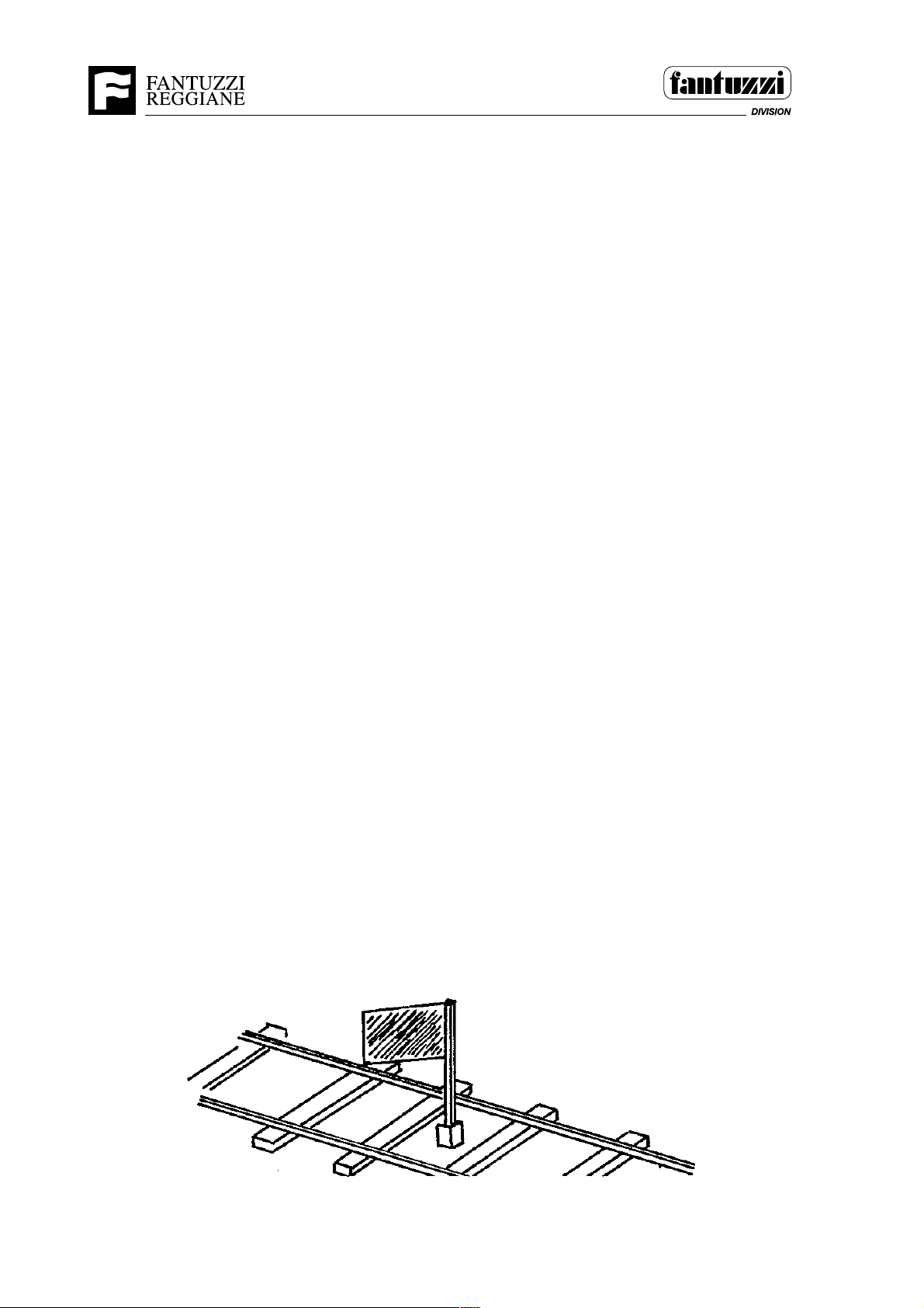
Do not work a track before it has been protected by a “blue flag” or some other
recognizable indicator.
Know your employer’s policies!
SMT.0033.E00
2 - 4 OP02.0012
1012
Page 33
Operator's Manual
Section 2 - General safety
SMT.0034.E00
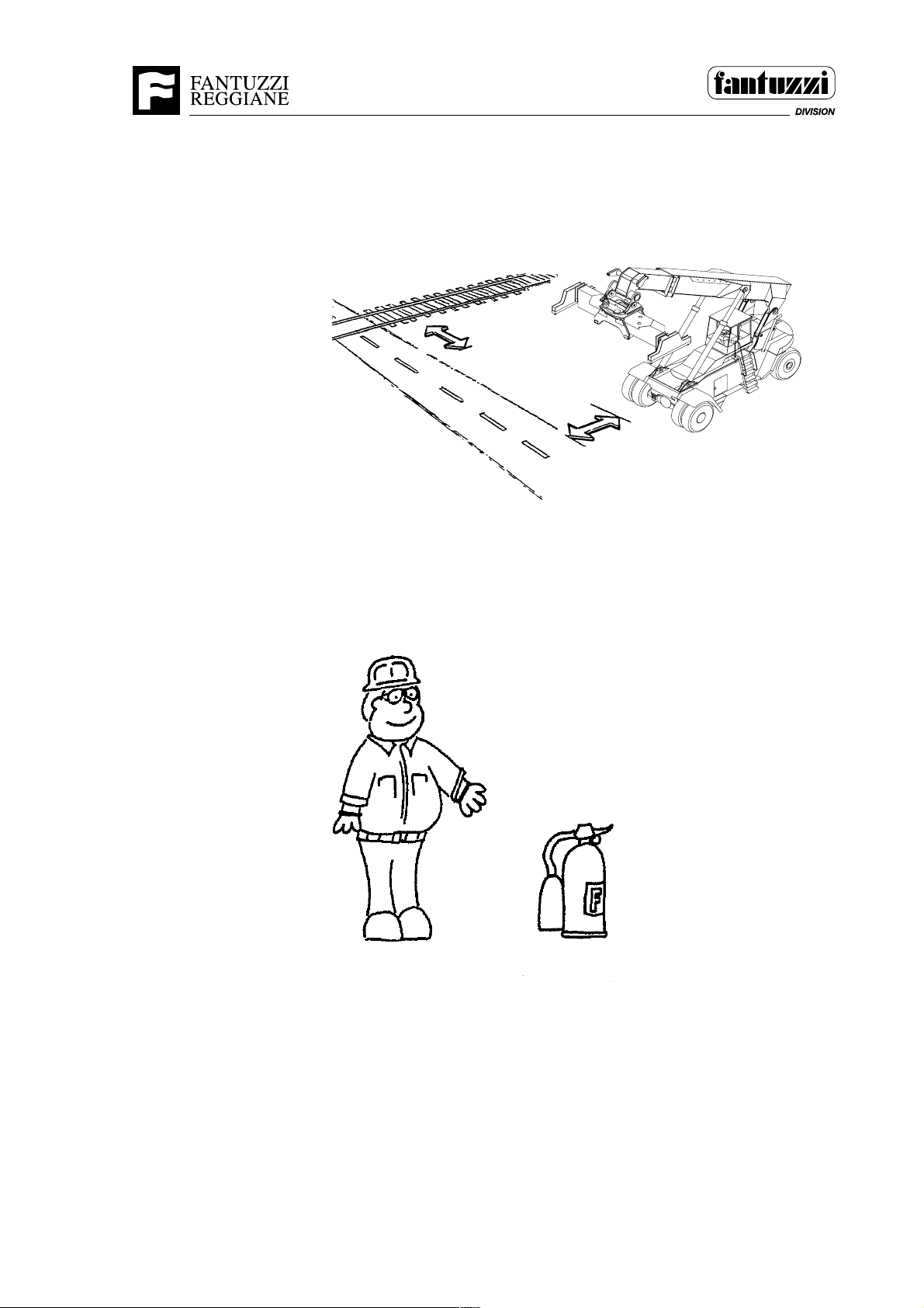
Always park the machine in a safe area away from tracks and truck lanes.
SMT.0034.E00
1014/1173
SMT.0036.E00
Know where the fire extinguishers are located and how to use them. Make sure they are
fully charged. If not, report it to your supervisor.
SMT.0036.E00
1019
SMT.0037.E00
All walking surfaces (steps, ladders, etc.) and hand railings must be free of ice, grease,
oil, or other materials that could cause or contribute to a slip or fall by personnel.
SMT.0037.E00
OP02.0012 2 - 5
Page 34
Operator's Manual
Section 2 - General safety
SMT.0038.E00
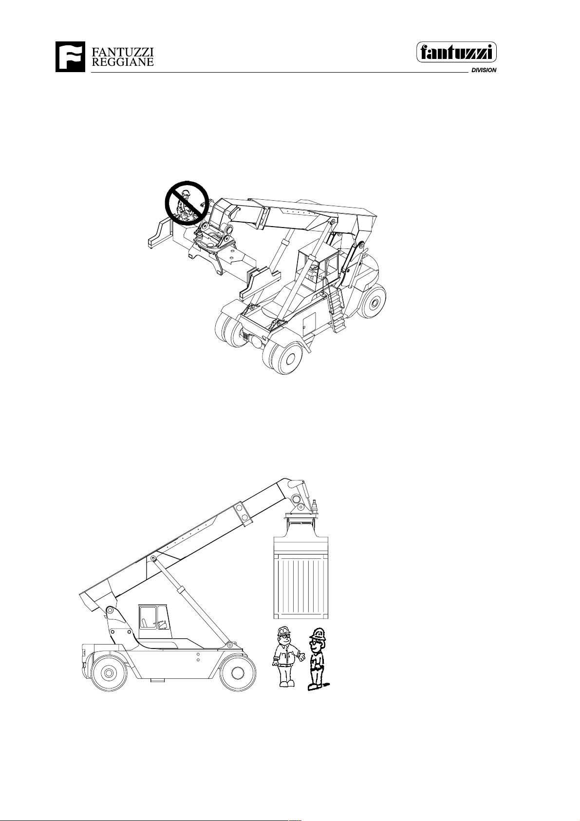
Never lift, lower, or move any person on the spreader, load, or attachment.
SMT.0038.E00
SMT.0044.E00
Do not allow personnel or vehicles to go underneath a load.
1015/1173
1177/1017
Do not add additional counter weights to the machine.
SMT.0044.E00
2 - 6 OP02.0012
Page 35
OP02.0011 2 - 7
Operator's Manual
Section 2 - General safety
SMT.1118.E00
CAUTION!
Hanging loads across passageways and work stations
Manoeuvres for lifting and transporting loads should be arranged so as to avoid hanging
loads passing over workers and anywhere that could be dangerous should the load
fall.
If this cannot be avoided, warnings must be given well in advance before lifting or
transporting loads so that, if practically possible, anyone who could be exposed to the
dangers of a possibly falling load has plenty of time to move out of the area.
The range of action of the lifting and transporting means, tted with electromagnets,
suction pads and clamps for gripping the load, must be cordoned off with barriers or,
wherever this is impossible because there is not enough room, all the necessary safety
precautions must be taken to ensure the safety of all personnel.
SMT.1118.E00
PROTECTION
SMT.0029.E00
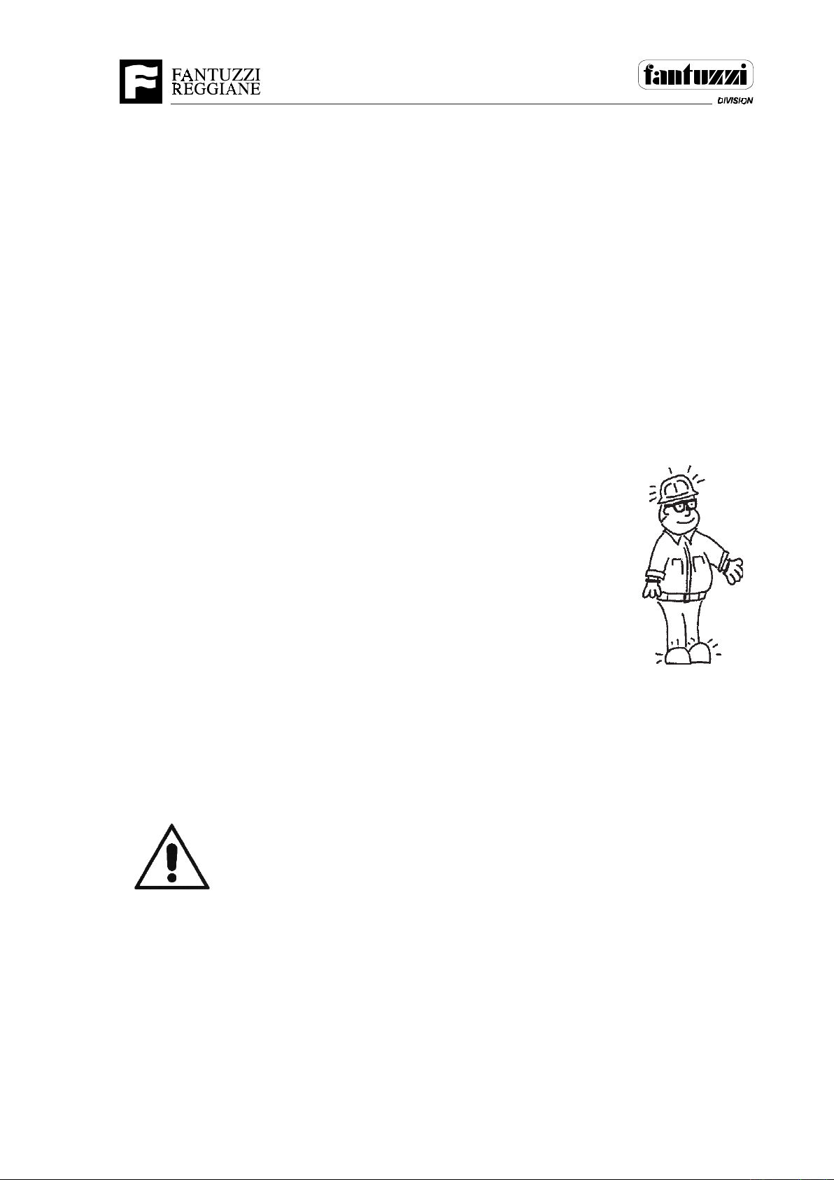
Wear the correct safety equipment; Safety glasses, hardhat, safety
shoes/boots as established by your employer’s safety policy. DO NOT
wear loose clothing. If required, obtain additional safety equipment
which may include but is not limited to; Ear protection, reective clothing and gloves.
SMT.0029.E00
1009
GET ON AND GET DOWN
SMT.0030.E00
When going up and down ladders, always face the ladder and use both hands. Do NOT
carry objects in one hand while climbing up or down.
SMT.0030.E00
SEAT BELT
General information and terms of use
Warning:
Accidents can have severe consequences if the seat belt is not fastened
properly.
To ensure a proper safe function, the seat belt must be fastened properly
and the back rest must be in an upright position.
The seat belt must be grabbed by the strap and pulled smoothly, then crossed over
the abs.
Insert the metal section into the locking latch (a locking noise must be heard).
Pull the belt to ensure proper tightening and latch.
In case the passenger seat is not equipped with restraining measures, it must be
used only when the machine is not in a running condition.
SMT.1473.E00
Page 36
Operator's Manual
Section 2 - General safety
ELECTRIC LINE
DANGER
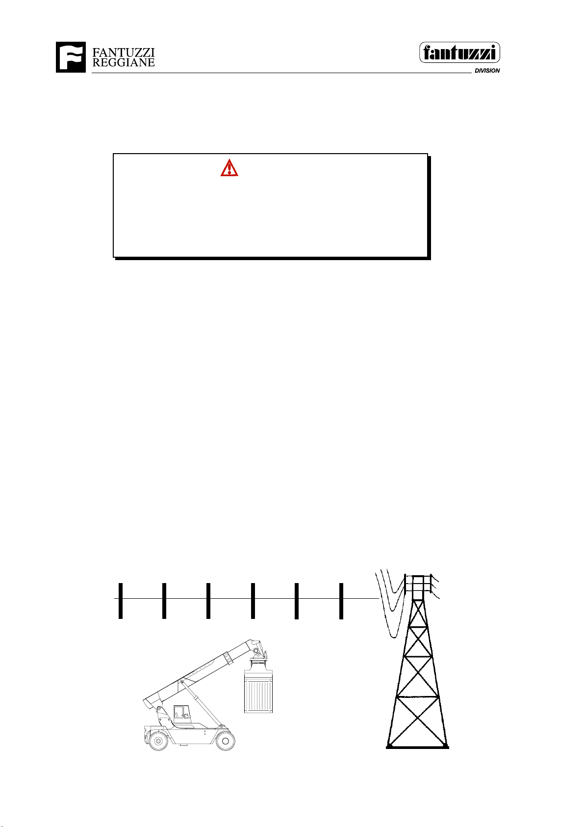
NEVER operate the machine under electrical power lines.
Electrical energy under high voltage can discharge to ground
through the machine without direct contact with the machine’s
structure, resulting in possible personal injury or death.
SMT.0041.E00
SMT.0039.E00
Minimum clearances from energized power lines or other power sources must be kept.
In Italy statute DPR 164 art. 11 states that a minimum distance of 5 meters should be
maintained whatever the voltage. This value should be regarded as a minimum value and
it is meant that during manoeuvre no part of the load, machine or additional equipment
employed should violate this limit. You are adviced to refer to the following illustration
from OSHA recommended Electrical Conductor Clearance Chart. When in doubt,
contact your local Electrical Power Utility Company FIRST!
NOTE: Where local or other applicable safety codes or regulations specify
greater clearance distances, the local or other applicable safety codes or
regulations shall apply.
MINIMUM SAFE CLEARANCE
0 TO 50,000VOLTS 10 FT. ( 3.04 meters)
50,000 TO 200,000 VOLTS 15 FT. ( 4.56 meters)
200,000 TO 350,000 VOLTS 20 FT. ( 6.08 meters)
350,000 TO 500,000 VOLTS 25 FT. ( 7.60 meters)
500,000 TO 750,000 VOLTS 35 FT. (10.64 meters)
750,000 TO 1,000,000 VOLTS 45 FT. (13.68 meters)
13,68 m
(45 FT.)
10,64 m
(35 FT.)
7,60 m
(25 FT.)
6,08 m
(20 FT.)
4,56 m
(15 FT.)
3,04 m
(10 FT.)
1177
1016
2 - 8 OP02.0012
Page 37
Operator's Manual
Section 2 - General safety
If electricity does discharge through the machine, REMAIN IN THE CAB. DO NOT
PERMIT ANY PERSONNEL TO COME IN CONTACT WITH THE MACHINE’S
STRUCTURE.
Warn all personnel not to approach the machine.
To get away from the point of contact perform an opposite movement from the
previous one. To detach from the contact it is necessary to perform a more forcefull
movement from the original one.
When you are in a safe position stop the machine and inspect all the main parts before
resuming work.
If it is not possible to detach yourself from the line, and the machine has not caught fire,
remain in your place until the electric line has been switched off.
DANGER
If the electricity discharges towards the machine remain in the
cabine and stop other people from contacting the machine structure.
SMT.0040.E
If you have to leave the machine do not use the steps, but jump away from the machine
when possible. The ground around the electrified machine is aslo electrified in different
intensities. Get away by jumping with both feet together. Warn any helpers not to
approach unless a dry piece of wood has been placed.
SMT.0041.E00
OP02.0012 2 - 9
Page 38

Operator's Manual
Section 2 - General safety
OPERATING IN WIND
SMT.0046.E01
This machine has been tested for operating limits in wind, according to ISO 10525
standards (wind speed 44 Km/h. corresponding to degree 6 of the Beaufort scale).
SMT.0046.E01
SCAPPING THE MACHINE
SMT.0047.E00
If the machine has to be taken out of service indenately it should be completely deactivated and handled by a scrap metal dealer in the area.
If the machine has to be scapped, particular attention should be paid to :
- lubrication
- oil
- glass
- plastic
- battries
SMT.0047.E00
2 - 10 OP02.0012
Page 39
Operator's Manual
Section 3 - Safety guidelines
SECTION 3 • GROUNDCREW SAFETY GUIDELINES
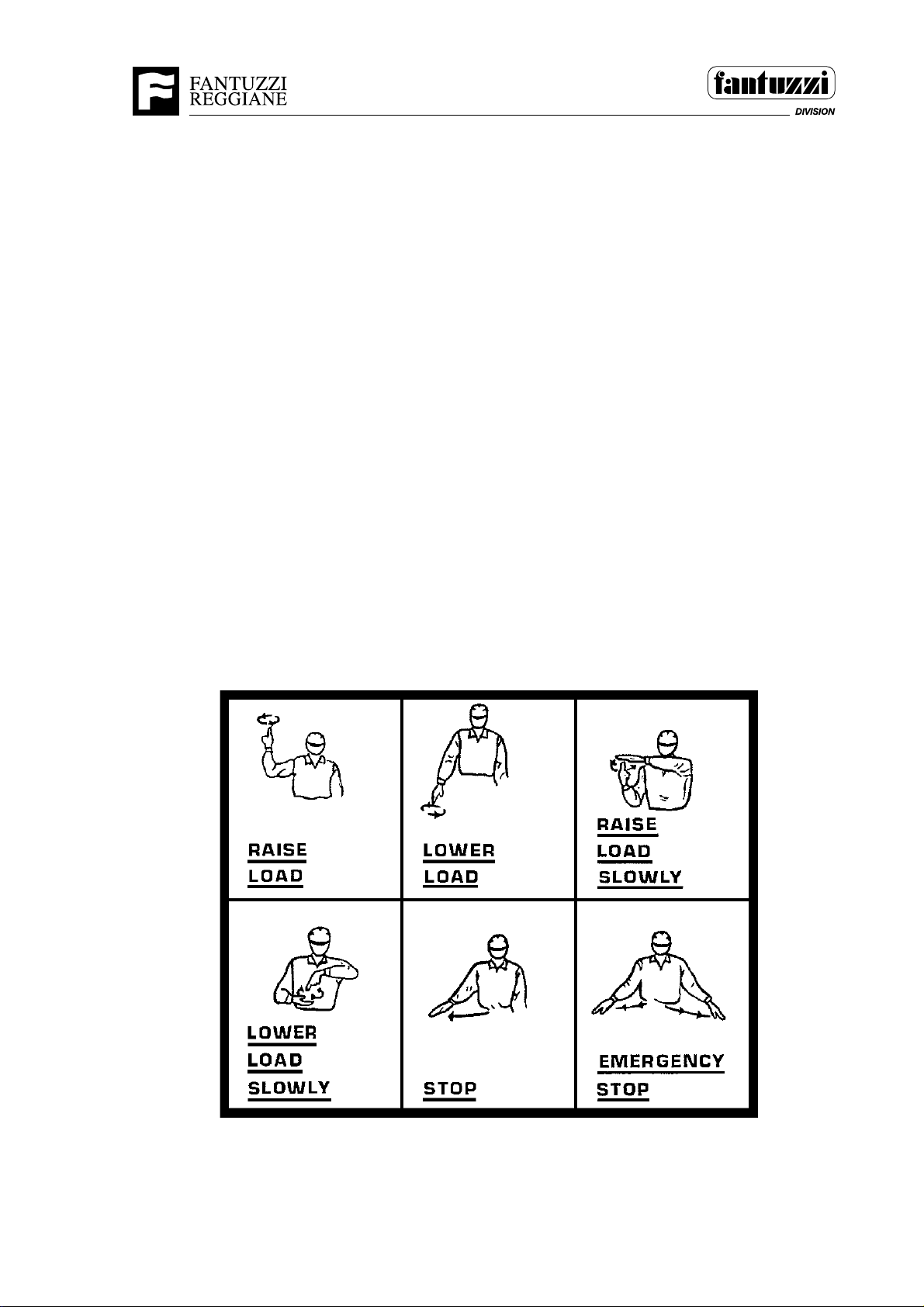
COMMUNICATION BETWEEN OPERATOR AND GROUNDCREW
SMT.0048.E00
All directional references are given as viewed from the operator’s seated position.
If ground persons are used in conjunction with the operation of this machine, clear
and precise communication between the operator and the groundcrew is a must for
safe and proficient machine operation.
The following signals are normally used with machine operation. The operator and
groundcrew should review them together prior to operating to ensure accurate
communication and to establish an “ALL CLEAR FOR MOVING THE MACHINE”
signal.
SMT.0048.E00
1020
OP03.0011 3 - 1
Page 40
Operator's Manual
Section 3 - Safety guidelines
RECOMMENDED SAFETY GUIDELINES FOR GROUNDCREW
SMT.0049.E00
The operator and the groundcrew (if used) must be in constant communication with each
other at all times. Review the communication system to be used before starting. Both
persons must know the proper hand signals for each movement of the machine or load.
If ground persons are utilized in conjunction with the operation of this machine, do not
move the machine without the proper signal from your groundcrew. The groundcrew
must be in the operator’s view at all times. The operator must stop the machine if the
groundcrew disappears from his view.
The operator and the groundcrew are to ensure that ALL ground personnel are out of the
machine’s entire hoist working area before hoisting a load and that the area remains clear
of personnel until the load is lowered safely to a suitable resting place.
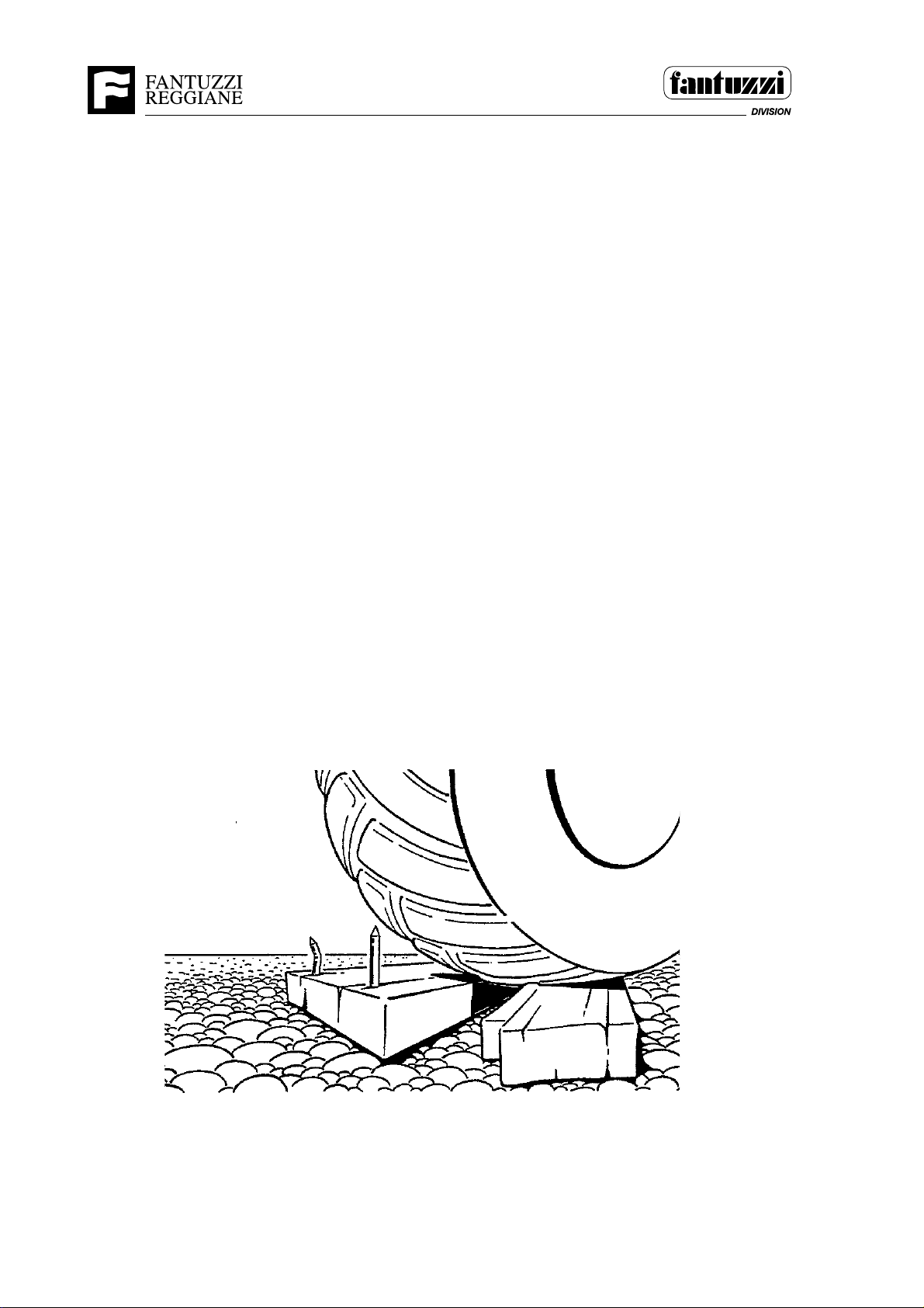
The groundcrew, if used, must keep the machine’s operating area free from debris that
could cause tire damage that may result in a tire blow-out and possible damage to
equipment.
SMT.0049.E00
1021
3 - 2 OP03.0011
Page 41
Operator's Manual
Section 3 - Safety guidelines
RESPONSIBILITIES OF THE GROUNDCREW FOR SAFE OPERATION
SMT.0051.E00
When groundcrew personnel are used in conjunction with the operation of this
machine, they are the eyes and ears of the machine operator. The machine, like any
other equipment, can be DANGEROUS if not operated properly. Before working
around the machine, the groundcrew is to be properly trained and are to understand
all of their responsibilities related to the machine’s operation.
The following are suggested responsibilities. There may be more. It is the
responsibility of the equipment user to establish the policies.
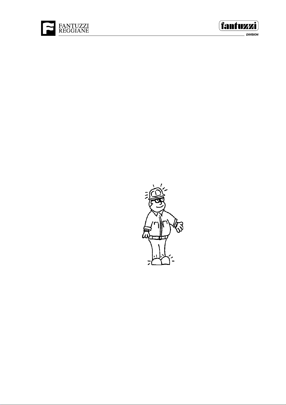
1. Wear proper protective clothing and equipment when working around the
machine; hard hat, safety shoes, safety glasses, hearing protection, reflective
vest or reflective clothing, gloves, etc. as established by your employer’s safety
policy.
1009
IMPORTANT: It is the employer’s responsibility to implement all precautions to
provide the employee(s) with all safety devices or means that may be necessary or
be required for any particular use: Operations, Set-up or Service. SMT.0050.E00
2. Give proper operation signals.
3. Do not give the operator a signal to move the machine until you and other ground
personnel are clear of all moving parts.
OP03.0011 3 - 3
Page 42

Operator's Manual
Section 3 - Safety guidelines
4. Know at all times where other groundcrew members are before signaling the
operator.
5. Never ride on any part of the machine other than designated seating areas.
6. Never walk or stand under suspended loads. If a load will be traveling over you,
move a safe distance away.
7. Be sure you check with the operator and make certain that he understands the
safety rules for groundcrew.
8. Do not stand between the machine and other obstructions or equipment.
9. Never ride on the load, or hang from any attachment.
10. Always stay clear of „blind spots“ and stand in full view of the operator or be
in constant radio communication with him.
11. Do not get closer than 6 ft. of the wheels of the machine when the machine is
moving. Stay clear of the steer wheels.
12. The groundcrew should be aware of other people in the area and warn them
that the machine is approaching them.
13. Do not turn your back on the machine. Always face it and keep it in full view at
all times.
SMT.0051.E00
DANGER
Stacks of containers or materials can cause “blind spots”
for the operator. It is essential, for safe operation, that the
groundcrew stay clear of “blind spots” and stay within
sight of the operator at all times. SMT.0052.E00
3 - 4 OP03.0011
Page 43

Operator’s Manual
Section 4 - Operator’s controls
SECTION 4 • OPERATOR’S CONTROLS
INDEX:
INTRODUCTION
INSTRUMENT AND CONTROL CAB LOCATION AND FUNCTION
INTRODUCTION
SMT.0067.E00
The following illustrations and explanations point out and describe the controls and
indicators used by the operator. The indicators may be lights or sounding devices.
The controls may be buttons, levers, knobs or keys.
IMPORTANT: Instrument readings, as indicated in this manual are based on normal
operating conditions. If the actual readings are different than indicated as proper,
shut down the machine and engine as soon as it is safe to do so, and report the
situation to appropriate maintenance personnel.
SMT.0067.E00
WARNING
Do not attempt to operate this machine before knowing and
understanding all of the safety and operating information in this
manual. SMT.0068.E00
OP04.0264 4 - 1
Page 44
Section 4 - Operator’s controls
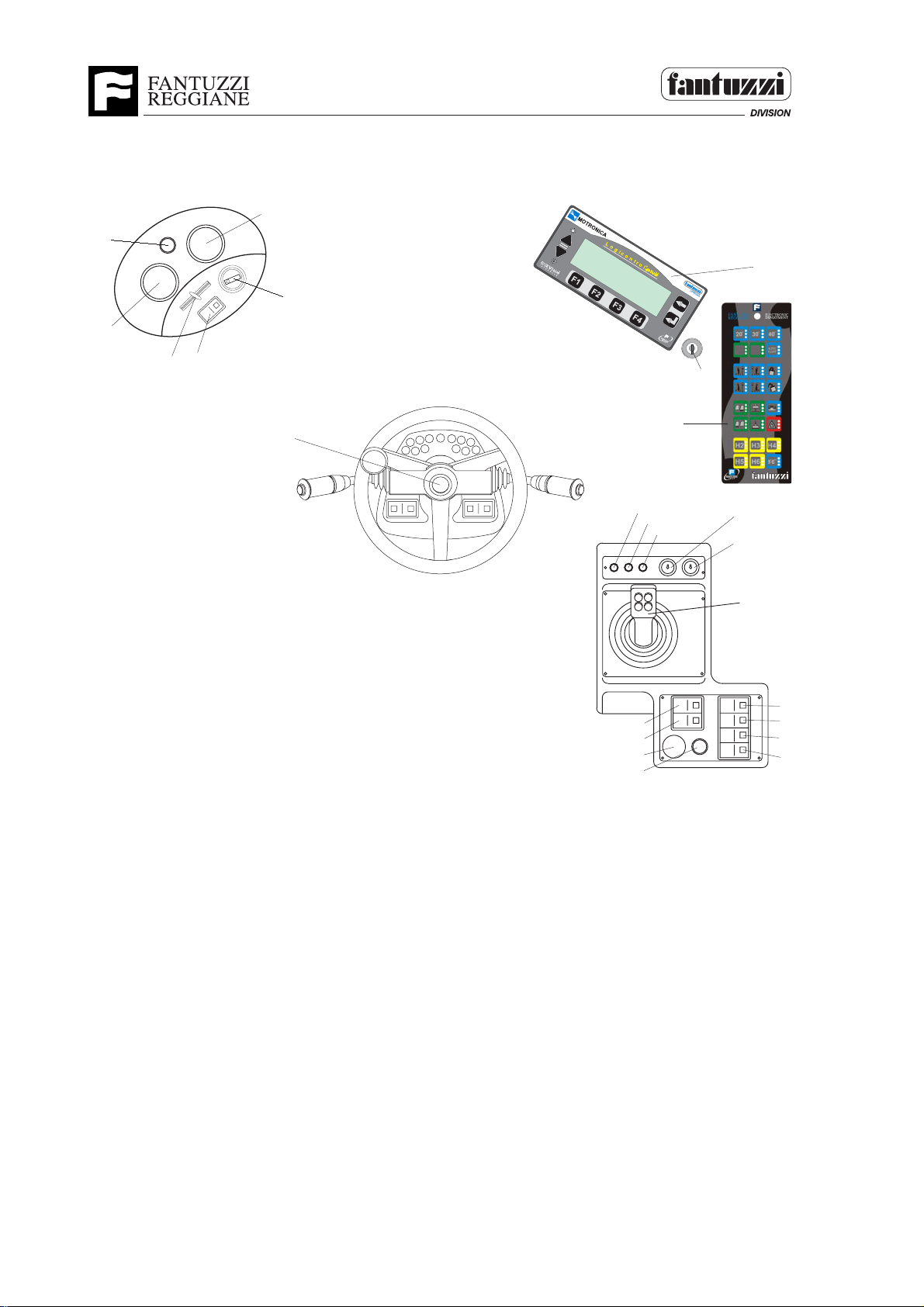
INSTRUMENT LAYOUT IN CAB
3
2
4
1
6
5
22
Operator’s Manual
4
5
3
2
6
1
10
8
9
7
11
13
12
7
7B
23
4839
8
1 Not used
2 Not used
3 Not used
4 Fan speed adjustment knob
5 Air conditioning/heating temperature regulation switch
6 Air conditioning switch (optional)
21
20
19
18
7 Load limiting device “Logicontrol Plus”
7B Anti-tipping bypass key (see the Logicontrol LMS Plus manual)
8 Twistlocks not fastened on indicator
9 Twistlocks rested indicator
10 Twistlocks fastened on indicator
11 Twistlocks by-pass key
12 Gear-change mode selection key
13 Joystick
14 Front windscreen-wiper switch
15 Upper windscreen-wiper switch
16 Rear windscreen-wiper switch
17 Heated rear windows switch
18 Parking brake button
19 Emergency button
20 Not used
21 Spreader opening-closing button
22 Steering wheel
23 Electronic keyboard of Logicontrol Plus
SMT.1175.E00
9
10
11
12
13
14
15
16
17
4 - 2 OP04.0264
Page 45
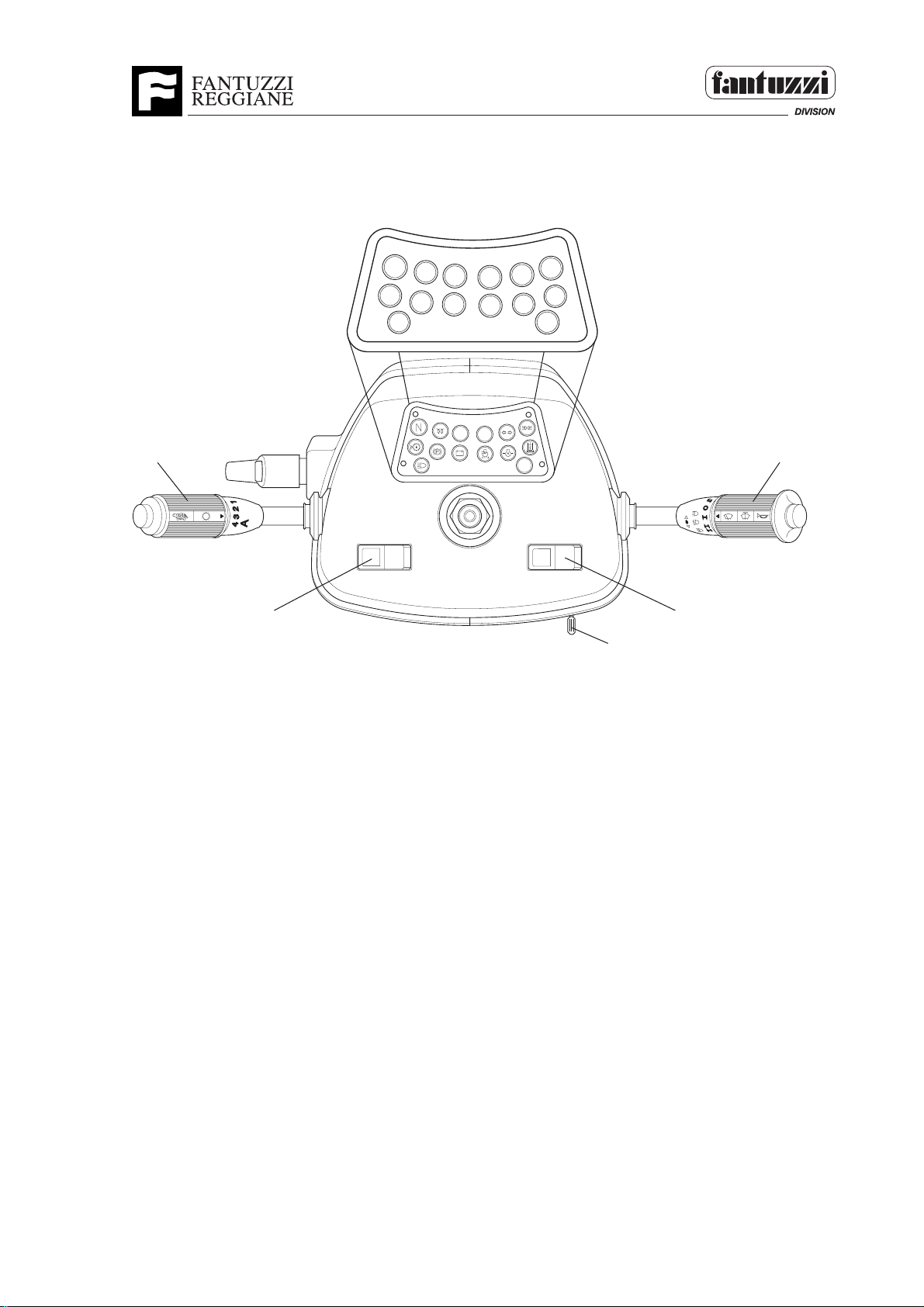
DASHBOARD
Operator’s Manual
Section 4 - Operator’s controls
3
4
5
6
9
10
11
12
15
2
1
1 Not used
2 Gear selector
3 Side light indicator
4 Upper beam headlight indicator
5 Direction indicators working indicator
6 Blocked oil filter indicator
7 Not used
8 Not used
9 Low motor oil pressure indicator
10 Blocked air filter indicator
11 Battery recharge fault indicator
12 Parking brake indicator
13 Glow plug preheating indicator
14 Low transmission oil level indicator
15 Neutral gear engaged indicator
16 Ignition key
17 Light – horn – direction indicators control
18 Work light switch
7
13
8
14
16
17
18
19
SMT.0659.E01
OP04.0264 4 - 3
Page 46
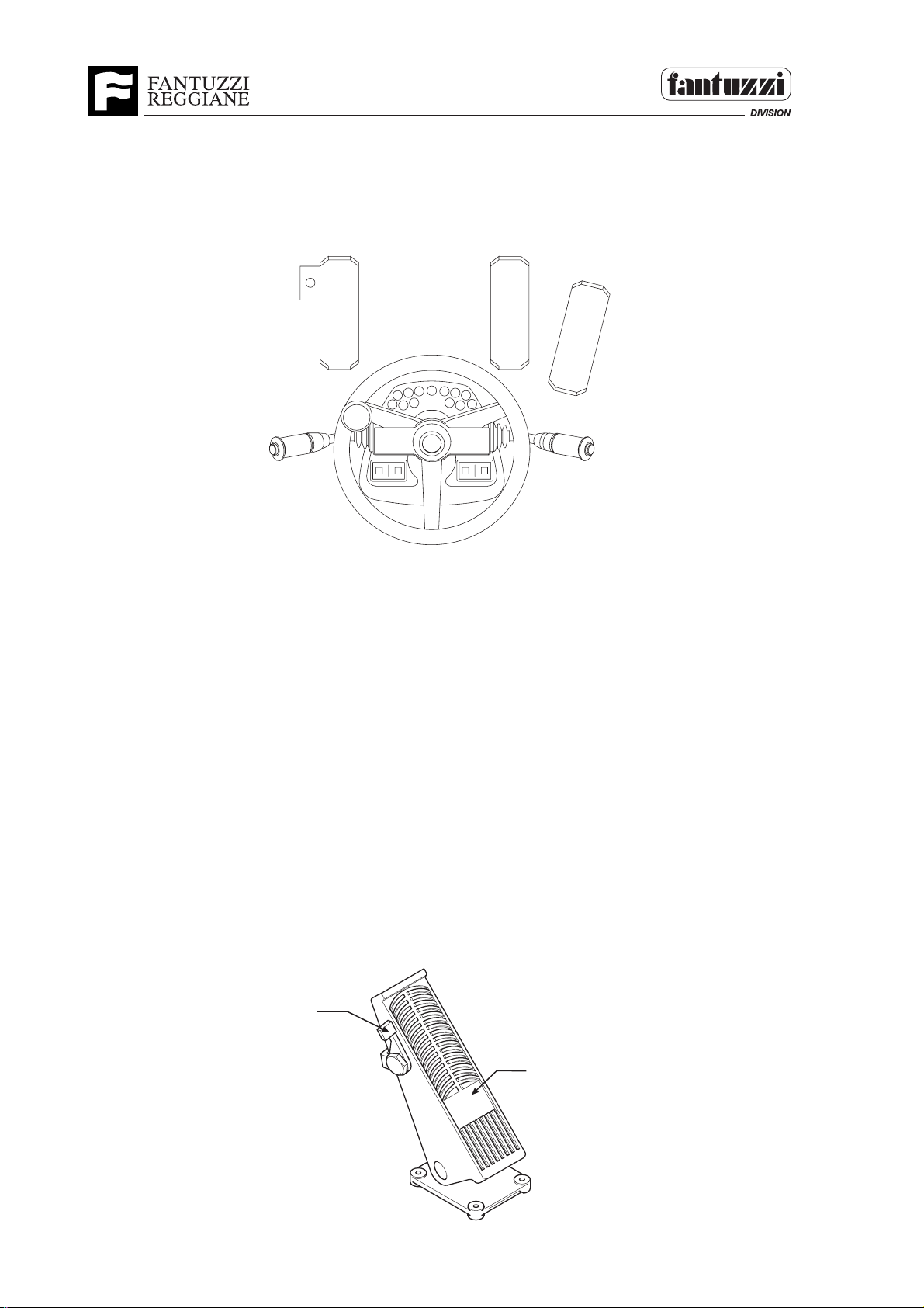
PEDALS
Operator’s Manual
Section 4 - Operator’s controls
1 - Brake pedal with switch
2 - Brake pedal
3 - Accelerator pedal
1
2
3
4
5
3
2
1
8
9
6
7
11
10
13
12
1992
Brake pedal with switch
Function:
This pedal, located on the far left, permits braking the machine and engaging the neutral
gear.
Procedure:
By keeping the pedal (1) pressed, the machine brakes, while keeping switch (2) pressed,
the machine brakes and the neutral gear is engaged. When the switch is released, if the
gear change is placed at forward or reverse, the relevant ratios will be engaged.
SMT.0565.E00
2
1
2465
4 - 4 OP04.0264
Page 47

Section 4 - Operator’s controls
INSTRUMENTS
(Indicator lights)
Upper beam headlight indicator
Function:
Indicates that the headlights are on.
Note:
if the warning light does not illuminate when the headlights
1521
are on, check the relative bulb and fuse.
SMT.0293.E01
Blocked oil filter indicator
Operator’s Manual
Function:
Indicates the oil filter clogged.
Note:
If the light stays on, seek technical assistance.
Do NOT use the vehicle if this warning light is on. SMT.0266.E01
1644
Low motor oil pressure indicator
Function:
Indicates lack of oil pressure in the engine.
Note:
When the ignition key is turned to position 1, this light will
1645
normally be on. It should go out when the engine is started.
If not, stop the engine. If the problem persists, seek technical
assistance. NEVER use the vehicle if this warning light is on.
SMT.0086.E01
Blocked air filter indicator
Function:
Indicates that the air filter is clogged.
Note:
If the light stays on, seek technical assistance. Do not operate
the machine until the malfunction is resolved. SMT.0087.E01
1646
OP04.0264 4 - 5
Page 48
Section 4 - Operator’s controls
INSTRUMENTS
(Indicator lights)
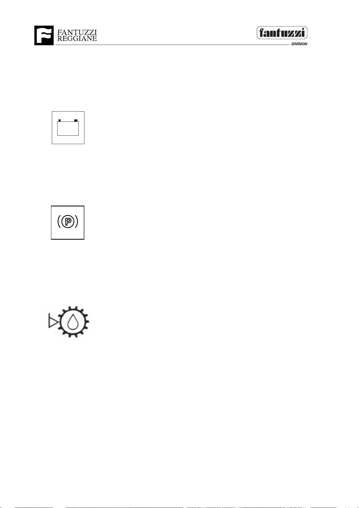
Battery recharge fault indicator
Function:
-
+
Indicates that the generator is not charging the battery.
Note:
with the key turned to pos. 1 in the ignition, the battery charging
1516
light is normally illuminated. When the motor starts the light should
go out. If not, seek technical assistance. Do not attempt to use the
vehicle without having corrected the fault, as this may damage the
batteries. SMT.0085.E01
Parking brake indicator
Operator’s Manual
Function:
Indicates that the parking brake is on.
Note:
This light must not be on when starting to drive. If the light remains
1514
on after releasing the parking brake, seek technical assistance.
Do NOT drive the vehicle without having first corrected the fault as
this could damage the braking system.SMT.0092.E01
Low transmission oil level indicator
Function:
It indicates the lack of oil in the transmission.
Note:
If this light stays on, check the transmission oil level by way of
1647
the sight glass.
Do NOT use the vehicle if this warming light is on.
SMT.0091.E01
4 - 6 OP04.0264
Page 49

Operator’s Manual
Section 4 - Operator’s controls
INSTRUMENTS
(Indicator lights)
Side light indicator
Function:
Indicates that the headlights are on. SMT.0082.E01
1523
Direction indicators working indicator
Function:
Indicates that one of the turn indicators is on. SMT.0089.E01
1522
Glow plug preheating indicator
Use:
Preheat the glow plugs before starting the motor, for not longer
than 5 secs.
SMT.0088.E01
1520
OP04.0264 4 - 7
Page 50

Section 4 - Operator’s controls
INSTRUMENTS
(Indicator lights)
Neutral gear engaged indicator
Function:
Indicates that the gear selector is in neutral.
Note:
The engine will not start if the vehicle is in gear, therefore always
1046
check that this light is illuminated before starting the engine. If the
engine still does not start even when this light is on, check that the
transmission is in fact in neutral.
SMT.0090.E01
Twistlock light
Function:
If the green light is on the twistlock are latched.
1732
If the red light is on the twistlock are unlatched.
If the amber light is on the container is in position and the twistlock
can be latched or unlatched.
SMT.0307.E00
Operator’s Manual
4 - 8 OP04.0264
Page 51

Operator’s Manual
Section 4 - Operator’s controls
CONTROL SWITCHES
NOTE: The windscreen wiper controls are protected by a thermal cutout that disengages
the motor in the event of excess strain such, as, for instance, using the wiper on a dry
windscreen. Add some anti-frost to the cleaning liquid when the temperature drops below
0° to prevent icing-up which would prevent spraying the water on the windscreen.
SMT.0537.E00
Front windshield wiper and washer
Function:
Operate the front windshield wiper at low.
Pressing this switch when the wipers are working operates the
1032
wash pump.
SMT.0270.E00
Upper windshield wiper
Function:
Operate the upper windshield wiper.
SMT.0213.E00
1033
Rear windshield wiper
Function:
Operate the rear windshield wiper.
SMT.0077.E00
1032
Window Defrosters
Function :
Switches on the window defrosters.
1184
OP04.0264 4 - 9
SMT.0078.E00
Page 52
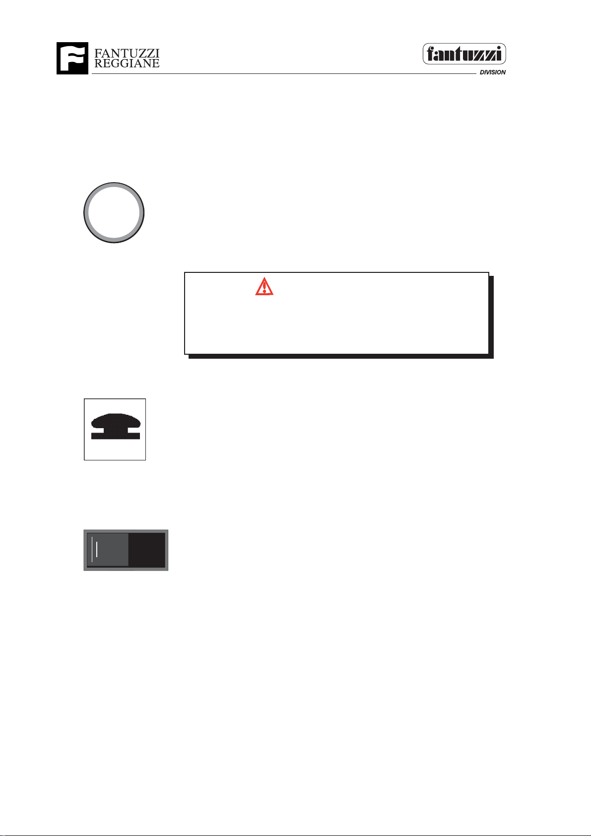
CONTROL SWITCHES
Parking brake button
P
1060
Operator’s Manual
Section 4 - Operator’s controls
Operation:
Apply the parking brake by pressing the button next to
the control levers. The light in the button will illuminate.
Note:
Always apply the parking brake and switch off the engine
before leaving the vehicle.
SMT.0101.E01
WARNING
Operating the vehicle with the parking brake on can
cause brake failure.
SMT.0093.E00
Emergency button
1571
Work light switch
1492
Function:
Stops the diesel engine.
Use:
Press the button when a machine movement could
represent a hazard for people or things and whenever the
machine has to be stopped as quickly as possible.
SMT.0306.E01
Function:
Switches on the working lights.
Note:
Essential when working in poorly lit areas. If the lights
do not work, check the condition of the relative fuse and
bulb.
SMT.0079.E00
4 - 10 OP04.0264
Page 53
Operator’s Manual
Section 4 - Operator’s controls
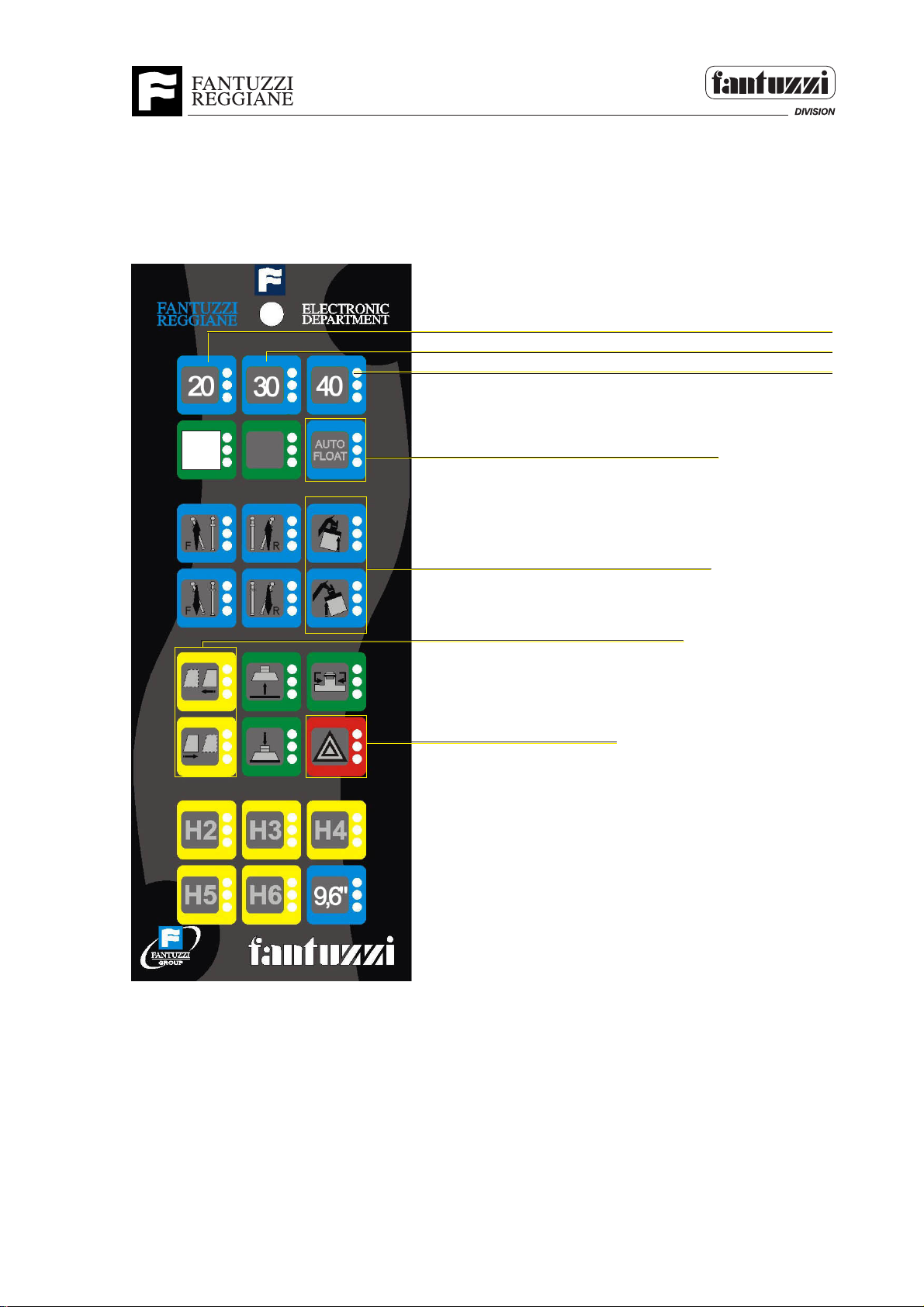
KEYBOARD OF LOGICONTROL PLUS
See the manual of Logicontrol Plus
Permits positioning the spreader at a 20' opening.
Permits positioning the spreader at a 30' opening.
Permits positioning the spreader at a 40' opening.
20’-40’
manual
Damping brake button
Damping movements
Cabin movements (OPTIONAL - see note *1)
Hazard
Note *1
Warning:
Cabin in forward position is allowed on approaching and locking operation ONLY.
In loaded driving conditions with a container, cabin MUST be in rear position.
OP04.0297 4 - 11
Page 54
Operator’s Manual
Section 4 - Operator’s controls
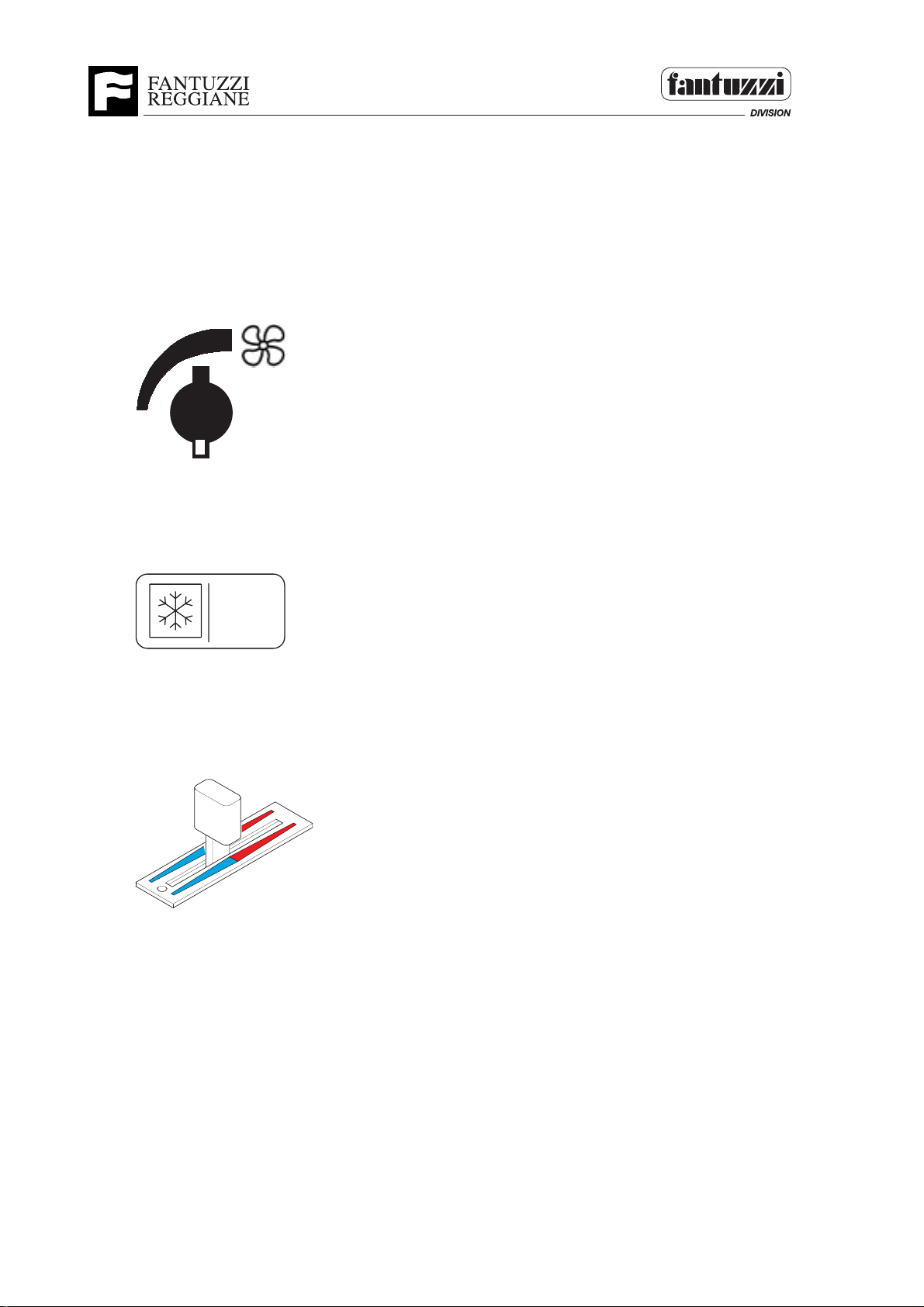
VENTILATION SYSTEM CONTROLS (where envisaged)
Fan speed adjustment knob
Turn the knob clockwise to increase the fan speed.
SMT.1034.E00
1728
Air conditioned button (optional)
Function:
For switching on the air conditioned.
How to use:
4642
To switching on the air conditioned it is necessary to set
the temperature regulation lever at the minimum value.
SMT.1035.E00
Air conditioning/heating temperature regulation lever
4643
4 - 12 OP04.0264
Page 55

Operator’s Manual
Off
2
3
1
Section 4 - Operator’s controls
KEYS
Ignition key
Function:
Start the machine motor.
How to use:
OFF - All circuits off, the key can be taken out.
1- Controls and instruments on.
1059
2- Motor glow-plug pre-heating (leave in this position for at most
5 seconds.).
3- Start motor (automatic return to pos. 1).
Note:
If the motor fails to start at first try, repeat the procedure.
SMT.0552.E00
Gear change mode selection key
Function:
For selecting either manual or automatic gear change.
Use:
To switch from automatic to manual gear change, turn the key to the right while the
machine is at a halt, with gear lever in “neutral” position
SMT.0309.E01
Auxiliary emergency pump ignition key (optional)
Use in case of fault in diesel engine or hydraulic system. By turning this key to the
right, the emergency pump is started, making possible arm, stabiliser and moving cab
movements. Do not leave on longer than necessary so as not to discharge the
batteries.
SMT.0529.E00
OP04.0297 4 - 13
Page 56
Operator’s Manual
Section 4 - Operator’s controls
SAFETY BY-PASS KEYS
WARNING
Keep the safety by-pass keys in a safe place. To use these, the
approval is required of the person in charge of the machine, who can
only use the key after finding the cause and possible remedy.
In case of faults being found, repairs must be made as quickly as
possible.
Function:
These keys operate switches in the cab and in the electrical compartment. The switches
interrupt the safety signals in order to finish handling a load or to fasten onto damaged
containers which would not tell the sensors to perform the operation.
Use:
To use the by-pass keys in the electrical compartment, the following two people are
required:
- One operator in the cab, to operate the controls
- One operator near the electrical compartment, to use the bypass keys.
Safety System by-pass key (in cab)
Function:
To restore functions of the telescopic boom movement.
Use:
In case of anti overtipping device malfunctioning, the same would inhibit boom
functions. Use the key to restore boom functions back to safe conditions.
SMT.1382.E00
Lifting by-pass key (in the electrical compartment)
Function:
Restores arm and twistlock lifting function in case of a twistlock sensor fault.
Use:
1- In the event of a container being handled and of a fault occurring to the “twistlock
locked-on” indicator sensor (green light on on the spreader and in the cab), this would
cause arm movement to stop immediately, except for re-entry movement. To
temporarily bypass the safety devices and terminate the operation, use the key.
Afterwards look for the fault and reset the sensors to return the machine to safety
condition.
2 - Use the key in the case of containers with damaged hook-on corner points.
This condition does not permit the sensors to complete twistlock hook-on rotation and
permission to lift is therefore denied.
For safety reasons, always repair the damaged corner hook-on housings of the
containers.
4 - 14 OP04.0264
Page 57

Operator’s Manual
Section 4 - Operator’s controls
Drop-stop by-pass key (in electrical compartment)
Function:
Restores arm downward movement function.
Use:
In the event of the container being damaged near the corner hook-on points or of faulty
proximity sensors, arm downward movement would be stopped to prevent damage to the
spreader and container.
Temporarily operate the bypass key to lower the arm and terminate the operation.
In the case of damaged sensors, repair these as quickly as possible and return the
machine to safety condition.
Leg opening by-pass key (in the electrical compartment and only for piggy-back
spreader)
Function:
This permits opening the legs of the piggy-back even without the approval of the
“supported container” sensors.
Use:
If a “supported container” sensor is damaged, permission to open the legs would be
denied even in the case of a supported container.
Use the key to release the container only once the container is perfectly supported.
Afterwards look for the fault and reset the sensors to return the machine to safety
condition.
Twistlock by-pass key (in cab)
Function:
This permits hook-on function even without the permission of the sensors that control
correct spreader position on the container.
Use:
In the event of the container being damaged near the corner hooks or of a fault occurring
on the “correct twistlock position” sensors, permission would not be given to fasten onto
the container.
Use the key to fasten onto the container once the spreader has been correctly positioned.
In the case of damaged container hook-on points or sensors, repair these as quickly as
possible and return the machine to safety condition.
SMT.0528.E00
OP04.0264 4 - 15
Page 58
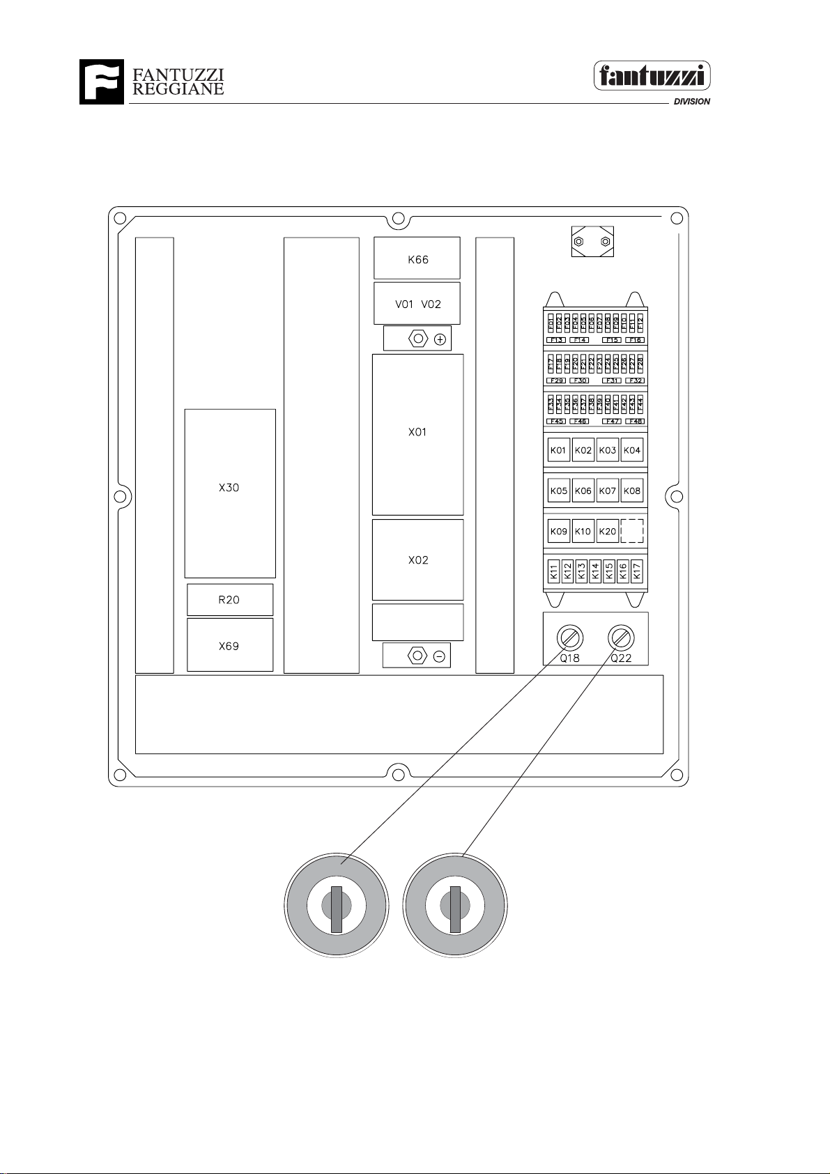
POWER CABINET
Operator’s Manual
Section 4 - Operator’s controls
12
1 - Drop-stop by-pass key
2 - Lifting by-pass key
4 - 16 OP04.0264
Page 59

Operator’s Manual
Section 4 - Operator’s controls
GEAR SELECTOR
Important: a safety device prevents the motor from being started unless the gear
switch is in neutral position. Before engaging the forward or reverse gear, make sure
the lever is in 1st gear position.
The truck features an automatic gear change, but can also operate in manual mode by
means of the transmission bypass key (see key paragraph).
Manual operation:
To engage 1st to 4th gears, turn the lever as shown in fig.1, while to drop from 4th to 1st,
turn the lever in the opposite direction.
Every click completed in turning the lever corresponds to a gear change.
The gear switch is in neutral position when it is configured as shown in fig.2
Move the switch as shown in fig.3 to engage the forward gear.
Move the switch as in fig. 4 to engage reverse gear.
Automatic operation:
Operation in this mode is similar to manual mode. The difference is that after having
engaged the forward or reverse gears, there is no need to turn the lever to change gear.
The number of gears the gear unit can engage automatically depends on the position of
the gear switch.
Example:
If the switch is turned in second gear, the gears engaged automatically will be 1st and
2nd, while the 3rd and 4th gears will not engage.
SMT.0544.E00
Fig. 1 Fig. 2
Fig. 3
Fig. 4
1948
3
4
2
1
OP04.0264 4 - 17
1
2
3
4
1
2
3
4
1
2
3
4
Page 60
Operator’s Manual
Section 4 - Operator’s controls
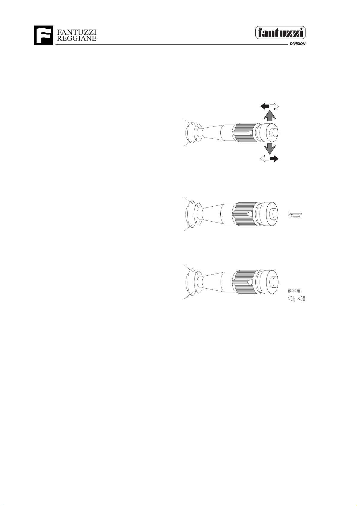
DIRECTION INDICATOR - HORN - LIGHTS LEVER
Direction indicators:
Push the lever forward to indicate a left turn;
Pull the lever back to indicate a right turn.
1535
Horn:
Press the end of the lever to sound the horn.
J
0
I
I
I
Lights:
To switch on the side lights, turn the lever to
position (I).
To switch on the dipped headlights turn the
lever to position (II).
To switch on the headlights turn the lever to
position (II) and press down.
To turn off the lights, turn the lever to position
(0).
To switch on the parking lights, turn the lever to
position (J).
NOTE: To flash the lights, repeatedly push the
lever up.
SMT.0304.E01
1538
1539
J
0
I
I
I
J
0
I
I
I
4 - 18 OP04.0264
Page 61
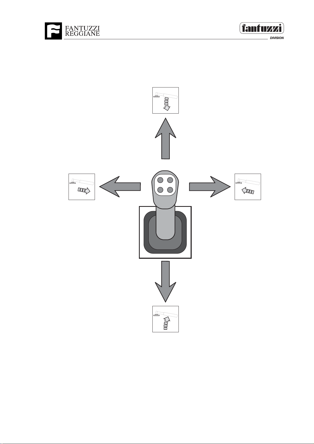
JOYSTICK CONTROL
Operator’s Manual
Section 4 - Operator’s controls
1301
The joystick fitted to this truck features a capacitive sensor known as «dead man’s
handle». This is an electronic safety device, fitted inside the joystick, that inhibits
functions when the operator releases the grip. This prevents operations being performed
accidentally if a button is accidentally pressed. SMT.0225.E01
OP04.0264 4 - 19
Page 62
Operator’s Manual
Section 4 - Operator’s controls
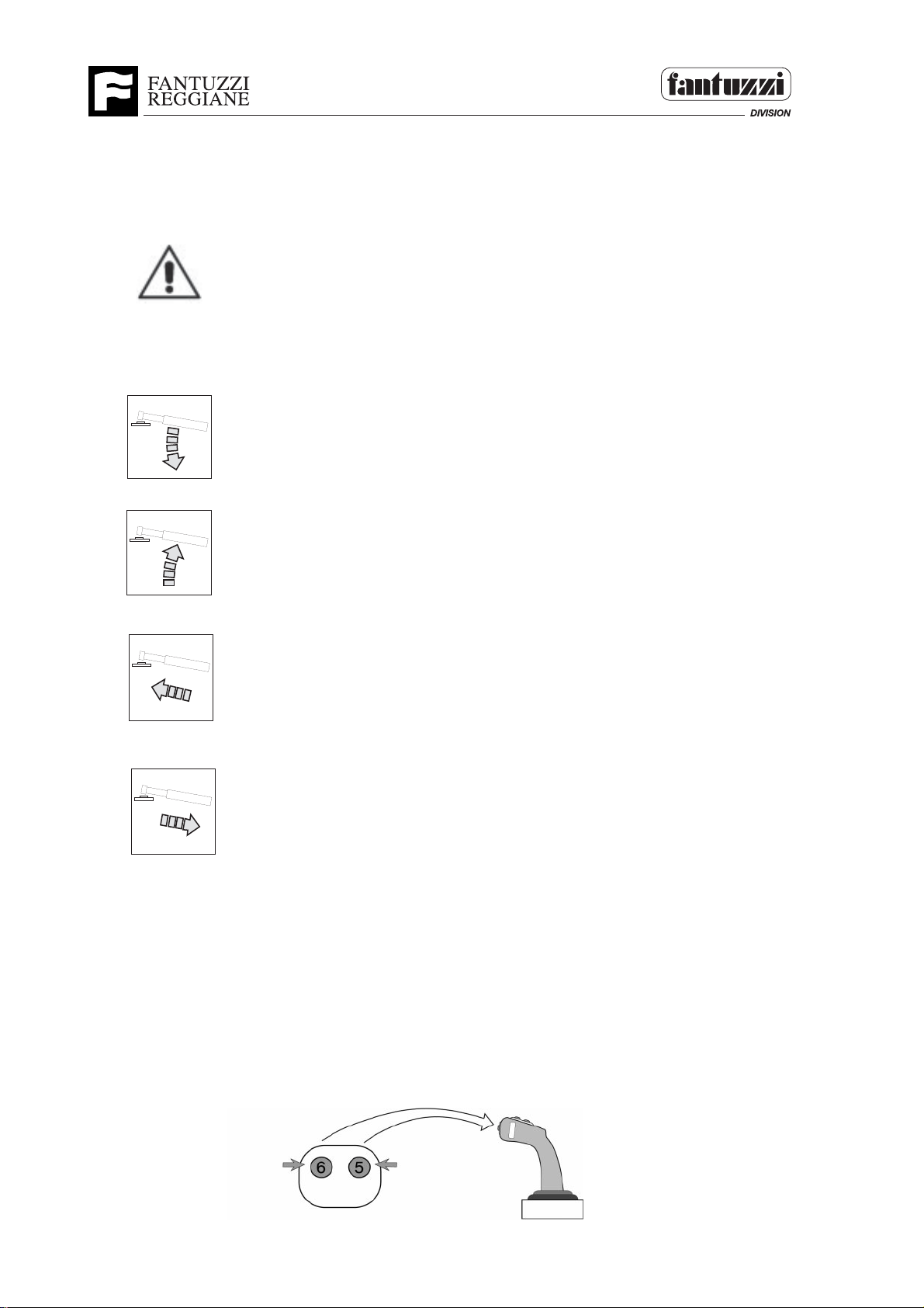
TELESCOPIC ARM MOVEMENTS:
Important: Operate the joystick gradually to prevent the telescopic
arm from making unexpected movements and undergoing
excessive strain. To prevent these problems, reduce the number
of motor rpm while moving the telescopic arm.
Telescopic arm down:
Push the joystick away from you to lower the arm.
1206
Telescopic arm up:
Pull the joystick towards you to lift the arm.
1208
Telescopic arm extension:
Move the joystick to the right to increase arm extension.
1205
Telescopic arm return:
Move the joystick to the left to reduce arm extension.
1207
SMT.0539.E00
TWISTLOCK ROTATION CONTROLS
Function:
These two buttons turn the twistlocks so the container can be gripped and released.
Use:
Press button 5 to release the container. Press button 6 to grip the container.
SMT.0548.E00
3013
4 - 20 OP04.0264
Page 63
Operator’s Manual
Section 4 - Operator’s controls
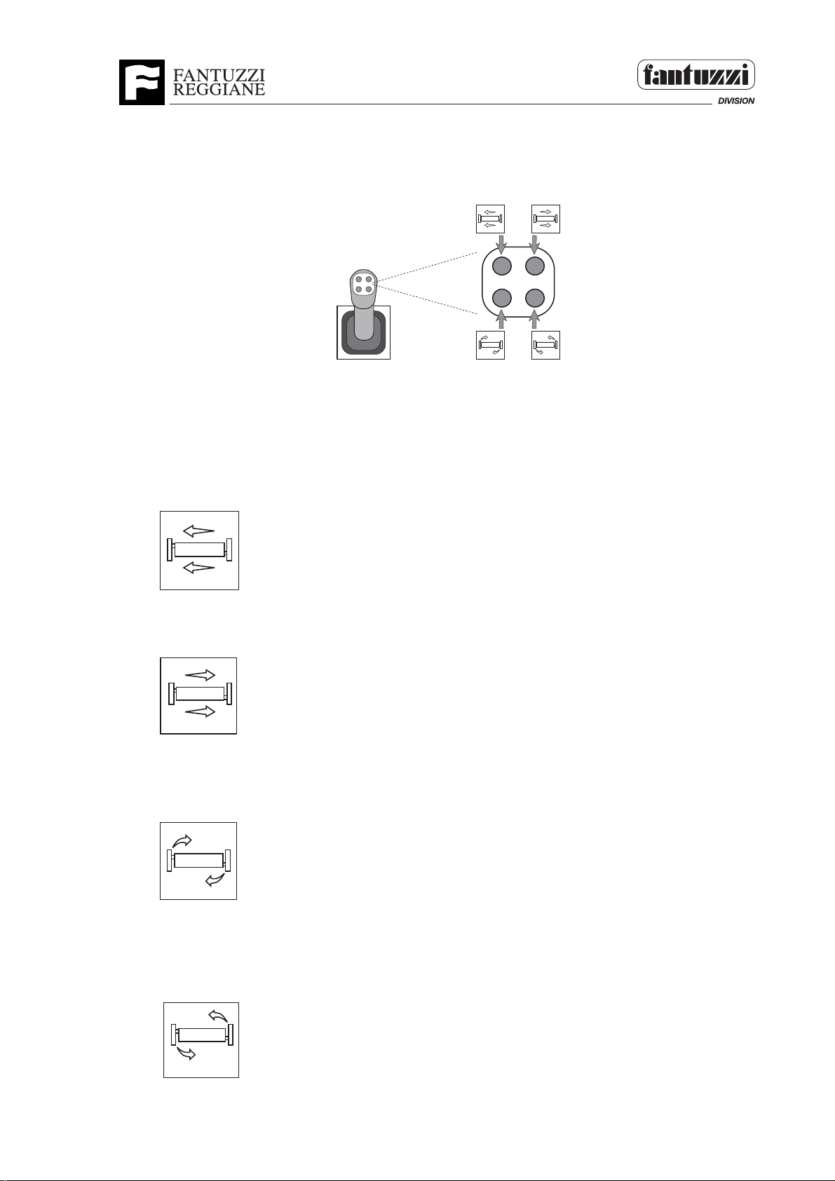
SPREADER TRANSLATION AND ROTATION CONTROLS
2
1
3
4
1303
The translation and rotation functions enable the spreader to be centred above the
container.
1 - TRANSLATION OF SPREADER TO LEFT
Press button 1 to move the spreader to the left.
1074
2 - TRANSLATION OF SPREADER TO RIGHT
Press button 2 to move the spreader to the right.
1073
3 - CLOCKWISE ROTATION OF SPREADER
Press button 3 to turn the spreader clockwise.
1076
4 - ANTICLOCKWISE ROTATION OF SPREADER
Press button 4 to turn the spreader anticlockwise.
SMT.0540.E00
1075
OP04.0264 4 - 21
Page 64
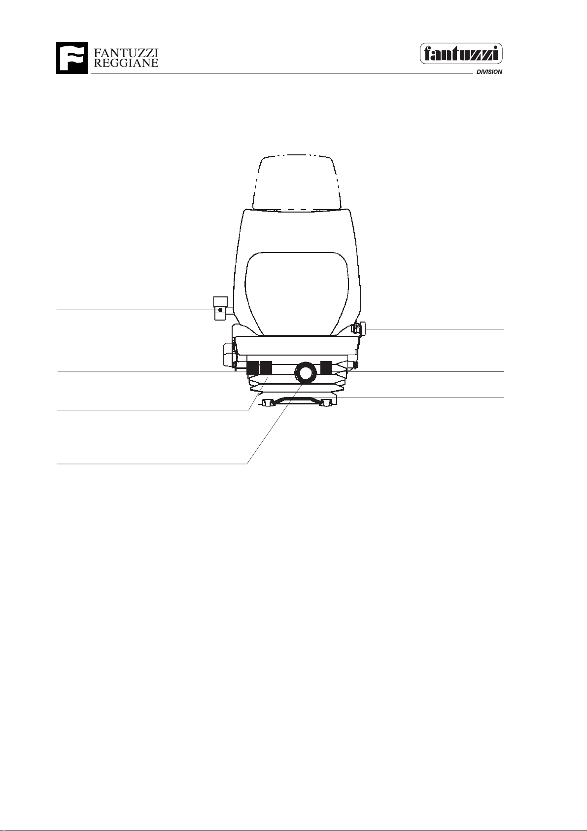
SEAT ADJUSTMENTS
Arm rest inclination
Operator’s Manual
Section 4 - Operator’s controls
Safety belt
Seat height adjustment
Seat inclination adjustment
Weight adjustment
1. Adjusting seat height
Turn the knob anticlockwise to lift the seat.
Turn the knob clockwise to lower the seat.
2. Adjusting the seat dampers
Push the lever to the right to increase damper resistance.
Push the lever to the left to reduce damper resistance.
3. Distance of seat from control panel
Lift the metal bar and slide the seat.
Seat backrest angle
adjustment
Forward / Backword
adjustment
4. Inclining the seat back
Lift the lever and regulate the back position as required.
SMT.0254.E01
4 - 22 OP04.0264
Page 65

Section 5 - Operating procedures
SECTION 5 • OPERATING PROCEDURES
INDEX:
INTRODUCTION
PRE-OPERATIONAL INSPECTION
ENGINE START-UP PROCEDURE
WARM-UP PROCEDURE
DRIVE
TRAVELING
STEERING
LOAD HANDLING
STOPPING THE ENGINE
PARKING PROCEDURE
Operator’s Manual
INTRODUCTION
SMT.0114.E00
There are certain operating procedures for this machine that must be followed for
safe, efficient operation. These procedures are simple, yet important. They are
based on common sense and incorporate the design characteristics of the machine.
FANTUZZI-REGGIANE Spa does not recommend the operation of any function other
than steering while driving (traveling) this machine. It is imperative that the operator’s attention not be diverted away from the moving of the machine.
IMPORTANT: Be sure you follow the start-up and warm-up procedures when placing
the machine into service.
SMT.0114.E00
WARNING
When operating this machine, if any abnormal condition in its operation
occurs, move the machine to a safe parking area, if possible, and when
safe to do so, shut down the machine and notify appropriate maintenance
personnel. SMT.0115.E00
OP05.0013 5 - 1
Page 66
Operator’s Manual
Section 5 - Operating procedures
WARNING
Electrical, mechanical, and hydraulic safety devices have been
installed on this machine to help protect against personal injury
and/or damage to equipment. Under no circumstances should
any attempt be made to disconnect or in any way render any of
these devices inoperative. If a malfunction of any safety device is
discovered to exist, DO NOT operate the machine. Immediately
notify appropriate maintenance personnel, otherwise serious
personal injury or death could result. SMT.0116.E00
SMT.0117.E00
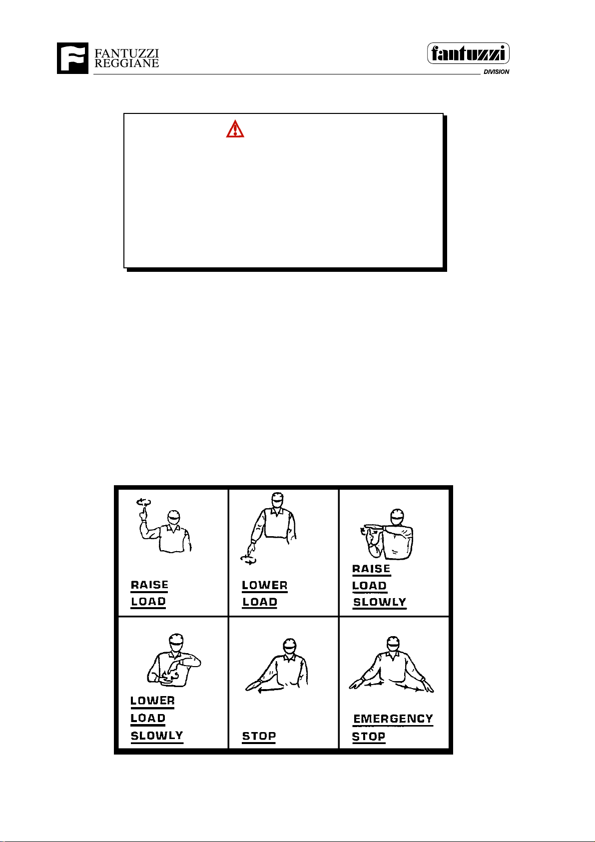
IMPORTANT: If ground persons are used in conjunction with the operator of this
machine, clear and precise communication between the operator and groundcrew is a
must for safe and proficient machine operation.The following signals are normally used
with machine operation. The operator and groundcrew should review them together prior
to operating to ensure accurate communication and to establish an “ALL CLEAR FOR
MOVING THE MACHINE” signal.
SMT.0117.E00
1020
5 - 2 OP05.0013
Page 67

Operator’s Manual
Section 5 - Operating procedures
PRE-OPERATIONAL INSPECTION
SMT.0118.E00
The following inspections are to be performed prior to each shift. You must know how
to properly do these. These inspections may be performed by either the maintenance
personnel or by you, the operator. In either case, it is your responsibility to be sure
that the machine is ready for operation prior to starting. Instructions for making the
checks are provided on the following pages.
NOTE: If maintenance tasks are to be performed, refer to the appropriate service
manual for your machine.
Prior to starting the engine:
Engine Crankcase ........................... Check oil level.
Radiator............................................ Check coolant level.
Hydraulic Reservoir ......................... Check oil level.
Oil Leaks .......................................... Visually check for oil leaks
Structure-Chassis & Spreader ........ Check for loose or missing Fasteners, cracks
and deformation.
Tires.................................................. Check general condition and pressure
appears low.
Operator’s Cab ................................ Clean thoroughly, including windows.
Fire Extinguisher(s) ......................... Check for full charge.
After starting the engine (running at idle)
Hydraulic Filters ............................... Check visual indicators
(if available).
Transmission Oil .............................. Check oil level (warm).
Fuel Tank ......................................... Check fuel level (*).
Lights ................................................ Check work, drive and indicator lights for
proper operation.
Warning Devices.............................. Check horn, strobe lights, & Back-up alarm
for proper operation.
Windshield Wipers ........................... Check for proper operation
Operator’s Controls ......................... Check for proper operation
Brakes .............................................. Be sure they operate before driving
(traveling).
Dash display .................................... Check all indicator lights and gauges for
proper operation of respective systems.
Unusual sounds ............................... Listen for unusual sounds or noises from
engine, transmission or hydraulic system.
(*) The fuel tank should be filled at the end of each day or shift.
SMT.0118.E00
OP05.0013 5 - 3
Page 68
Operator’s Manual
Section 5 - Operating procedures
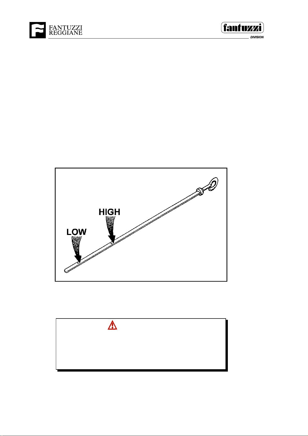
Motor Oil Level
SMT.0119.E01
The motor oil level must be checked every day.
NOTE: A 15 minute drain back time is required if the engine has been running.
The oil level must be maintained between the “H” (high) mark and the “L” (low) mark, but
as close to the “H” mark as possible.
SMT.0119.E01
1077
CAUTION
Never operate the engine with the oil level below the “L” (low)
mark or above the “H” (high) mark. Refer to the engine’s
OPERATION and MAINTENANCE manual for detailed engine
service. SMT.0120.E01
5 - 4 OP05.0013
Page 69
Operator’s Manual
Section 5 - Operating procedures
Motor coolant level
Sight check the level of the coolant in the tank.
Perform the inspection when the motor is cold and make sure the level is between
minimum and maximum.
SMT.0121.E01
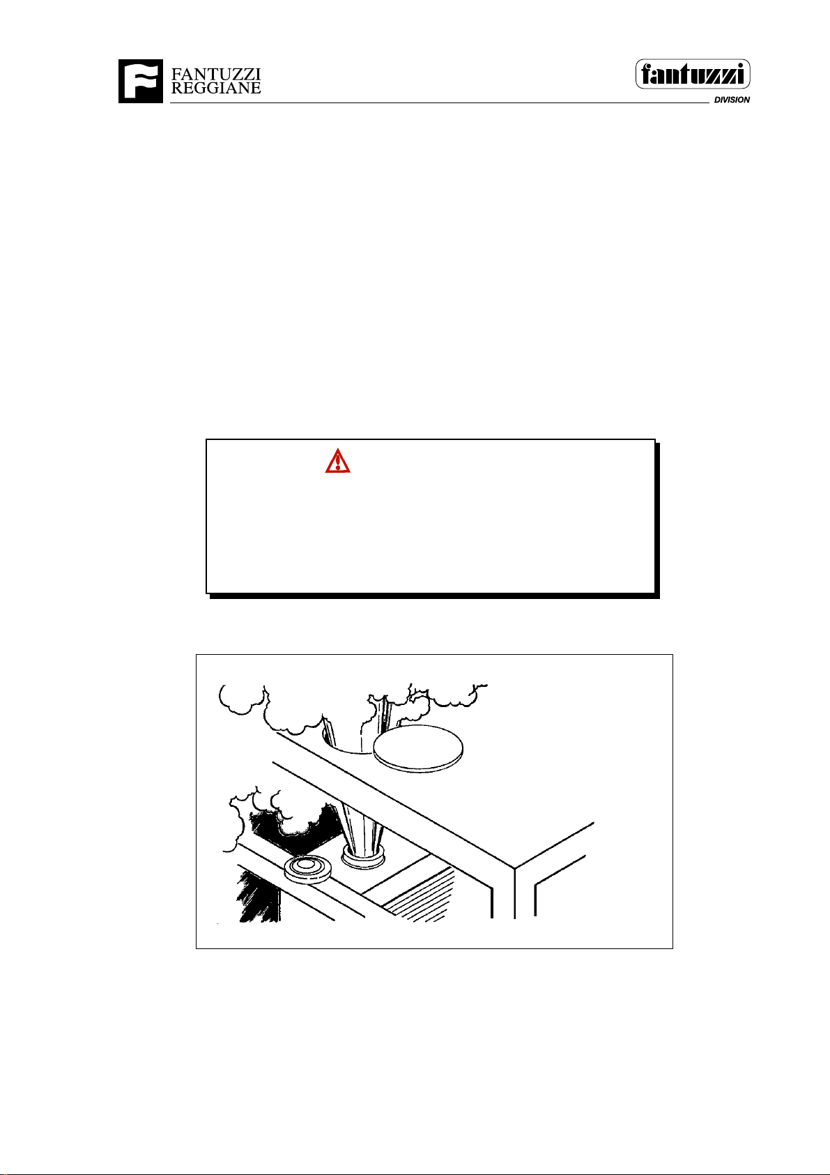
WARNING
Do NOT remove the radiator cap or the filler cap if the engine is hot.
The coolant will be under pressure and can escape with explosive
force. To prevent burns, remove the radiator cap or filler cap only
when the engine is cool. SMT.0122.E00
1078
OP05.0013 5 - 5
Page 70
Operator’s Manual
Section 5 - Operating procedures
Hydraulic Oil Level
SMT.0123.E00
The hydraulic oil reservoir is located on the chassis to the right of the driver’s seat.
Check the level of the hydraulic oil with the motor switched off. Make sure the level
reaches the top notch. Before topping up, make sure the area around the filler cap
is clean. Only use oil taken from a clean container.
SMT.0123.E00
WARNING
Do not check or change the hydraulic oil level before it has
cooled down. SMT.0124.E00
WARNING
Do not do any welding or have oxyhydrogen welding flames
near the hydraulic oil tank. SMT.0125.E00
Transmission oil level
Check the oil level every day, at a temperature between 82 – 93°C with motor running
at low revs. The oil level should always be at the FULL reference mark.
SMT.0126.E01
5 - 6 OP05.0013
Page 71
Operator’s Manual
Section 5 - Operating procedures
Leaks
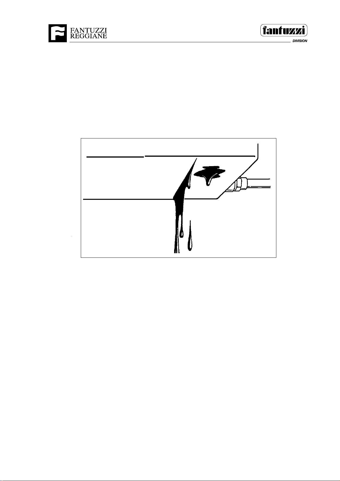
SMT.0128.E01
Make a sight check of the machine to find any oil or liquid leaks. All leaks must be
reported to appropriate maintenance personnel.
SMT.0128.E01
1081
OP05.0013 5 - 7
Page 72
Operator’s Manual
Section 5 - Operating procedures
Fuel tank
At the end of each work shift, fill up with diesel fuel.
SMT.0131.E01
DANGER
Be sure that there are no sparks, flames, or other ignition
sources present when refueling. A deadly explosion can result
if proper precautions are not taken. SMT.0132.E00
WARNING
Do not do any welding or have oxyhydrogen welding flames near
the fuel tank. SMT.0135.E00
5 - 8 OP05.0013
Page 73
Operator’s Manual
Section 5 - Operating procedures
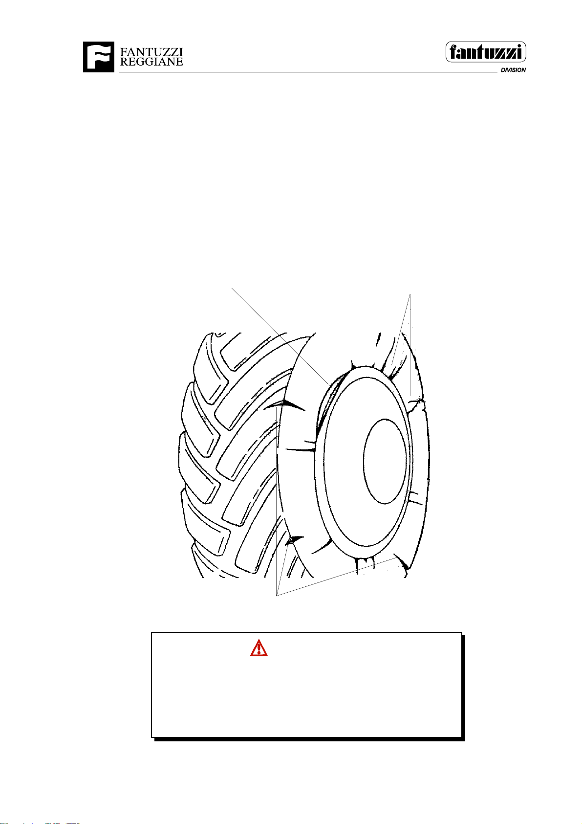
Tyres
Carry out a sight check of the pressure, the tread and the sides of the tyres. In case
of faults, the tyre will have to be carefully inspected by maintenance personnel before
being used. Also make sure that the rim and hub cap are not deformed.
SMT.0136.E01
deformed locking ring
sidewall damage
1083
tread damage
WARNING
A dislodged locking ring or exploding tire can be deadly to
anyone close to the tire or in the path of the dislodged, flying
ring. Only properly trained persons are to service the tires.
SMT.0137.E00
OP05.0013 5 - 9
Page 74
Operator’s Manual
Section 5 - Operating procedures
Operator’s Cab
SMT.0138.E01
Clean thoroughly after each shift, including the windows and mirrors. See
Remove all personal articles and trash to avoid its interfering with the operation of the
equipment.
SMT.0138.E01
Operator’s Controls
SMT.0144.E00
Check the operator’s control levers for smooth operation. All control levers should
return to neutral freely. There should not be any excessive play in the control
levers. Notify the appropriate maintenance personnel if any of these are not OK.
SMT.0144.E00
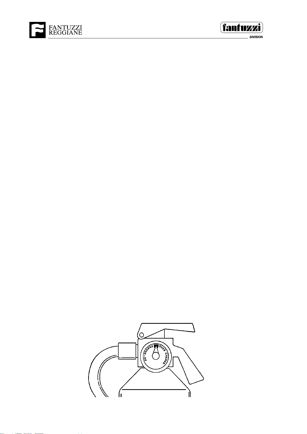
Dry powder fire extinguisher (optional)
SMT.0139.E00
Make certain the extinguisher is in its designated location, clearly visible and ready for
immediate use; there must be no obstructions hindering access. Check that the
appliance itself has not been interfered with or rendered unusable, also that the safety
seal preventing accidental operation is in place and the tamper indicators are intact.
Nameplates and labels must be exposed to view and clearly legible.
The extinguisher must be in faultless working order: no clogging of nozzles, no leakage,
no traces of corrosion, hoses securely connected and with no signs of cracking.
The pressure gauge must indicate a value within the green sector; if not, notify the
maintenance service. The fire extinguisher must be refilled every 36 months.
SMT.0139.E00
5 - 10 OP05.0013
1086
Page 75
Operator’s Manual
Section 5 - Operating procedures
Structure
Carry out a sight check of the machine component parts. In the event of faults being
found in the welded joints, or other faults in the structural load supporting component
parts, do not operate the machine and inform maintenance personnel.
SMT.0133.E01
DANGER
Do not pour inflammable liquids on hot surfaces in
order to avoid fires and explosions which can damage
the machine or injure the operator. SMT.0130.E00
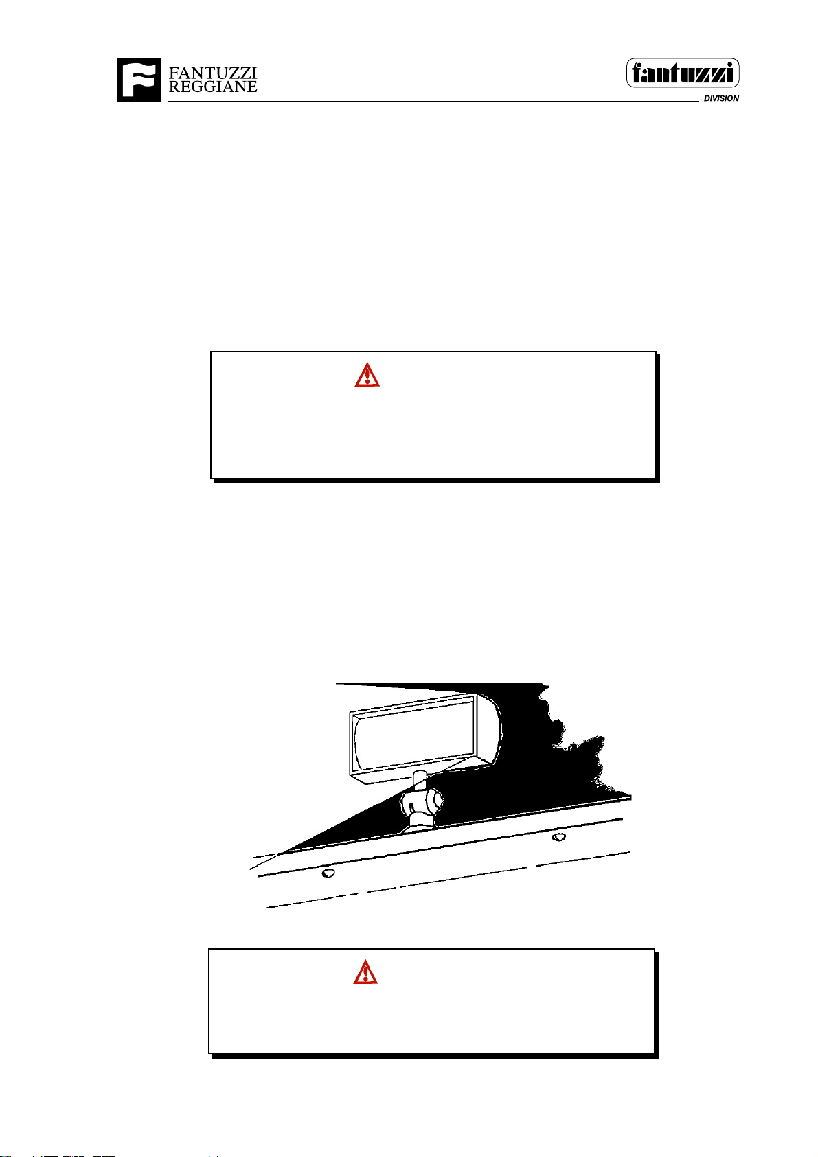
Lights
Check correct operation of the working lights, circulation lights and lights inside the
cab, especially in the case of night work. In the event of faults, inform the maintenance
personnel.
SMT.0140.E01
1087
WARNING
Do not operate when the visibility has deteriorated or obstructed
due to weather conditions, smoke or other causes. SMT.0141.E00
OP05.0013 5 - 11
Page 76
Operator’s Manual
Section 5 - Operating procedures
Warning Devices
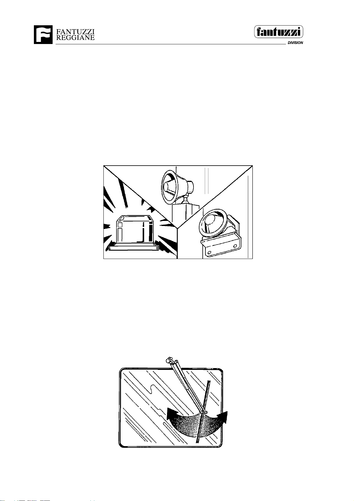
SMT.0142.E00
Warning devices are to alert ground personnel of the machine’s movement. Be sure
the horn, strobe lights, and back-up alarm are operating properly. The ignition key
should be in the ON position to check these devices. To check the back-up alarm,
reverse must be selected. However, it is not necessary to start the engine.
SMT.0142.E00
1089
Windshield Wipers
SMT.0143.E00
Check the windshield wipers for proper operation.
NOTE: Do not run the windshield wipers on a dry windshield to prevent scratches and
premature failure of the wiper blade.
SMT.0143.E00
1088
5 - 12 OP05.0013
Page 77
Operator’s Manual
Section 5 - Operating procedures
Welding
SMT.0134.E00
If near the welding joins there are cracks in the paint or it is flaking it is important to expose
the metal part and check the welding with penetrating liquids or equivalent methods. If
there are surface cracks get in touch with the assistance services to carry out the
necessary repairs.
SMT.0134.E00
DANGER
Do not carry out any welding operations or use
oxyhydrogen welding flames near the fuel tank. SMT.0127.E00
OP05.0013 5 - 13
Page 78
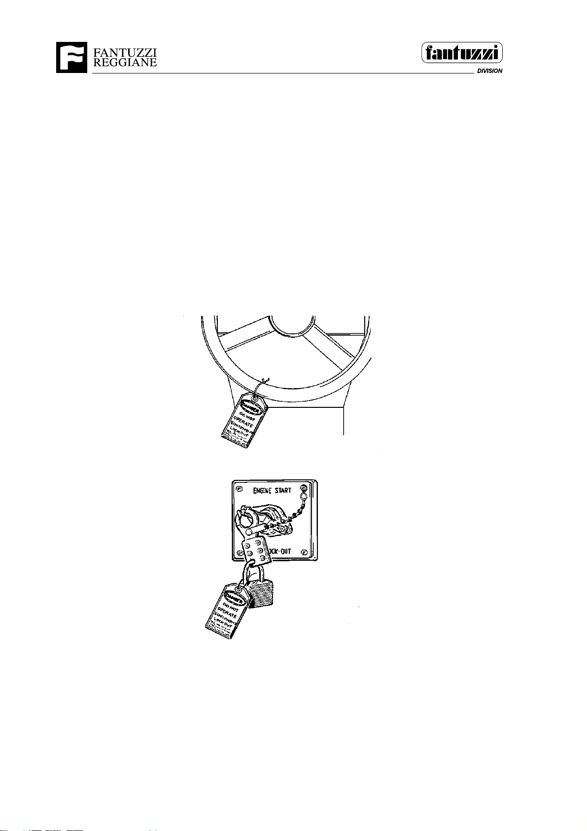
Operator’s Manual
Section 5 - Operating procedures
ENGINE START-UP PROCEDURES
SMT.0146.E00
Do not attempt to start the machine if it has been locked-out by maintenance
personnel or if the main power disconnect switch in the battery compartment is in the
OFF position. If in doubt, contact the maintenance supervisor.
SMT.0146.E00
1090
5 - 14 OP05.0013
Page 79
Operator’s Manual
Section 5 - Operating procedures
Normal Start
SMT.0148.E00
1. Adjust the seat.
2. Be sure that the parking brake is applied.
3. Place all the control levers in their neutral position.
AVVERTENZA
Suonare l’avvisatore acustico per avvisare il personale presente nella zona prima di avviare il motore. Accertarsi che
nessuno sosti nei pressi della macchina. SMT.0147.I00
4. Turn the ignition key switch to the START position and hold to start the
engine.
IMPORTANT: Do not operate the starting motor for longer than 15 seconds. In case
of starting failure wait 10 seconds between one start attempt and another.
SMT.0149.E01
5. Warm up the engine:
a. Engine and transmission oil pressures should rise immediately on engine
start. If the engine and transmission oil pressure warning lights do not go
off, STOP the engine and notify the appropriate maintenance personnel.
b. Temperature gauges will rise more slowly than pressure gauges.
c. The battery charge indicator should go off after starting to indicate a
normal battery charge rate. If not, STOP the engine.
6. Allow the engine coolant temperature to increase to the low end of normal
temperature range (approx. 104° F). Do not apply full load before the
temperature reaches 176°F.
7. Operate all controls slowly while the engine is warming up. Listen for any
unusual noises.
8. When the engine, transmission, and hydraulic system temperatures are in
the normal operating range, the machine is ready for use.
9. Test the braking system and then proceed to use the machine, taking all the
safety precautions indicated in this manual.
SMT.0148.E00
OP05.0013 5 - 15
Page 80

Operator’s Manual
Section 5 - Operating procedures
Cold Weather Start (Below 50°F)
SMT.0151.E01
NOTE: When temperatures are below 50° F (10°
C), attention is recommended
in starting the engine.
For maximum engine protection and easier starting at low temperatures, take the
following precautions:
1. Keep the batteries fully charged.
2. Keep the fuel clean and free of water.
3. Use lubricating oil with correct viscosity for the room temperature range
where the engine has to operate.
4. Pre-heat the glow plugs (keep the key in this position for a maximum of 5
seconds).
5. Start the engine.
SMT.0151.E01
5 - 16 OP05.0013
Page 81
Operator’s Manual
Section 5 - Operating procedures
Using Booster Batteries or Starting Generators
If the batteries on the machine are weak or discharged, use booster batteries or a starting
generator to start the engine.
IMPORTANT: DO NOT try to start the engine by towing or pushing.
WARNING
Booster batteries should only be connected by personnel
who have been specifically trained in their proper use.
Failure to connect booster batteries correctly could result
in severe personal injury and/or damage to equipment.
SMT.0152.E00
WARNING
Batteries contain sulfuric acid which can cause severe
burns. Avoid contact with skin, eyes, or clothing.
ANTIDOTES Recommended by Battery Manufacturers:
EXTERNAL ANTIDOTE: flush with water. Flush eyes for at
least 15 minutes. INTERNAL ANTIDOTE: drink large
quantities of water. Do not induce vomiting. CALL A
PHYSICIAN IMMEDIATELY AND GET PROMPT ATTENTION!
SMT.0153.E00
WARNING
Batteries produce explosive gasses when being charged or
discharged. ALWAYS wear eye protection when using
booster batteries and/or starting generators. Batteries can
explode if a spark or flame comes near the battery, possibly
causing serious injury. SMT.0154.E00
1. Make sure that parking brake is applied and all electrical controls are OFF.
OP05.0013 5 - 17
Page 82
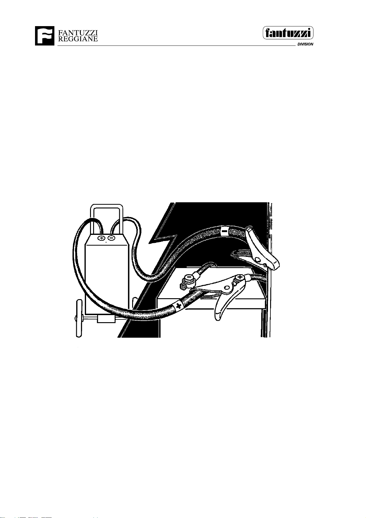
Operator’s Manual
Section 5 - Operating procedures
2. Connect the booster batteries or starting generator using the following procedure
to prevent a spark near the battery that can cause an explosion.
a. Connect one jumper cable to the positive (+) terminal of the booster battery.
Connect opposite end of the same jumper cable to the positive (+) terminal of
the battery on the machine.
b. Connect the other cable to the negative (-) terminal of the booster battery.
Connect the opposite end of this cable to a good ground connection on the
1091
machine’s frame, away from the battery.
3. Start the engine in the normal manner.
4. After the engine has been started, first disconnect the negative (-) booster cable
from the frame, then remove the positive (+) booster cable.
SMT.0156.E01
5 - 18 OP05.0013
Page 83

Operator’s Manual
Section 5 - Operating procedures
MACHINE HEATING UP PROCEDURE
If the machine motor has been shut off or has cooled down, this will have to be heated
up gradually so the coolant and the motor and transmission oil are brought to operating
temperature.
Recommended operating temperature:
Diesel engine coolant: 60 – 70 °C
Transmission oil: 80 – 90 °C
SMT.0157.E01
OP05.0013 5 - 19
Page 84
Operator’s Manual
Section 5 - Operating procedures
STOPPING THE ENGINE
IMPORTANT
A turbocharged engine must always be run at about 1000 rpm
with reduced load for 2 or 3 minutes before switching off in
order to allow the turbocharger to cool down.
SMT.0158.E01
SMT.0159.E01
1. Turn the key switch to the OFF position to turn off all electrical control circuits and
remove the starting key from the instrument panel.
2. Apply the parking brake.
3. If machine is so equipped and engine will be stopped for a prolonged period during
cold weather, plug in the engine block heater and/or hydraulic oil tank heater using
the correct socket for external power supply.
4. Disconnect the battery selector and reomve the key.
5. Close all locks before leavign the machine.
SMT.0159.E01
5 - 20 OP05.0013
Page 85
Operator’s Manual
Section 5 - Operating procedures
DRIVING
SMT.0163.E01
Handling the machine should be left to the authorised operator who knows its functional
features and load limits and who knows how to operate within the safety rules.
1. Adjust the operator’s seat to a comfortable and suitable position. Run the engine
at idling speed and select the driving direction and gear required with the gear
lever.
2. Release the parking brake.
3. To change to a higher gear, turn the gear lever to the next higher gear releasing
at the same time the accelerator. Accelerate normally after the gear has been
inserted; to go down the gears perform these actions in reverse order. To change
to lower gear turn the gear lewer to the previous gear releasing, and at the same
time releasing the accelerator.
4. When driving always use the right brake pedal.
SMT.0163.E01
CAUTION
Do not gear down until machine slows to appropriate
speeds. Otherwise, damage to the drive line can occur.
SMT.0162.E00
WARNING
Do not carry heavy loads in a raised position in order not
to compromise the stability when braking or driving on
irregular ground. SMT.0164.E00
WARNING
The machine’s inertial force resulting from its speed and
weight influences how quickly the machine can be stopped
just like any other vehicle. Because of the machine’s
gross weight, it cannot be stopped instantly. A variable
distance is required to stop the machine, depending on
load and speed. Be sure to allow stopping distance when
driving to avoid collisions. SMT.0165.E00
OP05.0013 5 - 21
Page 86

Operator’s Manual
Section 5 - Operating procedures
TRASLAZIONI
General information
The operator must comply with the highway code including the speed limits on the road
and on the worksite.
He/she must be able to clearly see the route and any traffic, personnel. Always
maintain safety distances.
The machine must always be kept under control and operated in a responsible manner.
Avoid sudden starts and stops and changes of direction at high speed.
The lifting unit and load must stay lowered so as to ensure full visibility for the operator.
The load must only be lifted during stacking.
In case of bad visibility or stacking difficulties, drive cautiously, using auxiliary means or
the assistance of adequately trained ground personnel.
Near crossroads and other points where visibility is low, reduce speed and indicate
presence by means of the horn.
Operate the steering and brake controls smoothly and moderately when handling high
loads.
Do not overtake other vehicles moving in the same direction near crossroads, points
where visibility is bad or hazardous areas.
The operator should not drive over objects that could damage tyres or the machine.
Indicate changes of direction using the direction indicators near other vehicles or
pedestrians.
SMT.0166.E01
5 - 22 OP05.0013
Page 87

Operator’s Manual
Section 5 - Operating procedures
Speed
SMT.0168.E01
The speed must be adapted to the presence of personnel in the area, visibility,
surface and load. Particular care must be taken on wet and slippery surfaces, such
as snow or ice. Under all conditions, the vehicle must be operated at a speed enabling
it to be brought to a stop in a safe manner.
SMT.0168.E01
Operating on gradients (slopes)
SMT.0169.E01
When operating on slopes, the following rules shall be observed:
1. The machine must move up and down slopes slowly.
2. Do not turn the machine on slopes, nor drive across slopes.
4. The load must be facing uphill when driving up or down gradients of over 10%.
SMT.0169.E01
OP05.0013 5 - 23
Page 88

Operator’s Manual
Section 5 - Operating procedures
STEERING
SMT.0171.E01
The machine is steered by turning the steering wheel in the direction that you want
the machine to go. The steering wheel opens and closes a valve to provide hydraulic
power to turn the steering wheels. There is no mechanical linkage between the
steering wheel and the steering system linkage.
Do not continue turning the wheel after reaching the turning limit so as not to cause
overheating of steering components.
Do not turn the steering wheel from one turning limit to another with the machine at
a standstill to prevent wear of tyres and floor.
To help maintain machine stability and to prevent possible tipping, do not steer
sharply, especially:
a. While traveling at higher speeds.
b. With spreader elevated to mid-point or above.
c. On uneven terrain.
SMT.0171.E01
5 - 24 OP05.0013
Page 89

Operator’s Manual
Section 5 - Operating procedures
LOAD HANDLING
IMPORTANT:
Always remain within sight and communication with personnel on the ground.
Do not lift submerged loads as water and mud increase weight.
Make sure frost has not secured the load to the ground.
Do not use the machine to push or pull loads.
Make sure that during operations, the load and machine do not knock against any
obstacle.
Lifting unit controls
The control functions of the lifting unit are described in detail in Section 4 of this
manual. The following safety functions will help the operator to safely handle the
container.
• Special sensors (position sensors) feature on each twistlock and send signals to
the electronic control system to confirm that the twistlocks have been correctly
positioned in the container corner hook-on housing.
• If this condition is satisfied, the yellow indicator light comes on and twistlock faston can start.
• When all the twistlocks have been correctly fastened, the green light comes on
and lifting can begin.
• Before releasing the twistlocks, the container must be rested on a sturdy and
stable support surface.
• If properly supported, the yellow light comes on to indicate that the twistlocks can
be released.
• To confirm all the twistlocks have been released, the red light comes on.
• In the event of a fault, the electronic control system prevents raising the lifting unit.
SMT.0172.E01
OP05.0013 5 - 25
Page 90
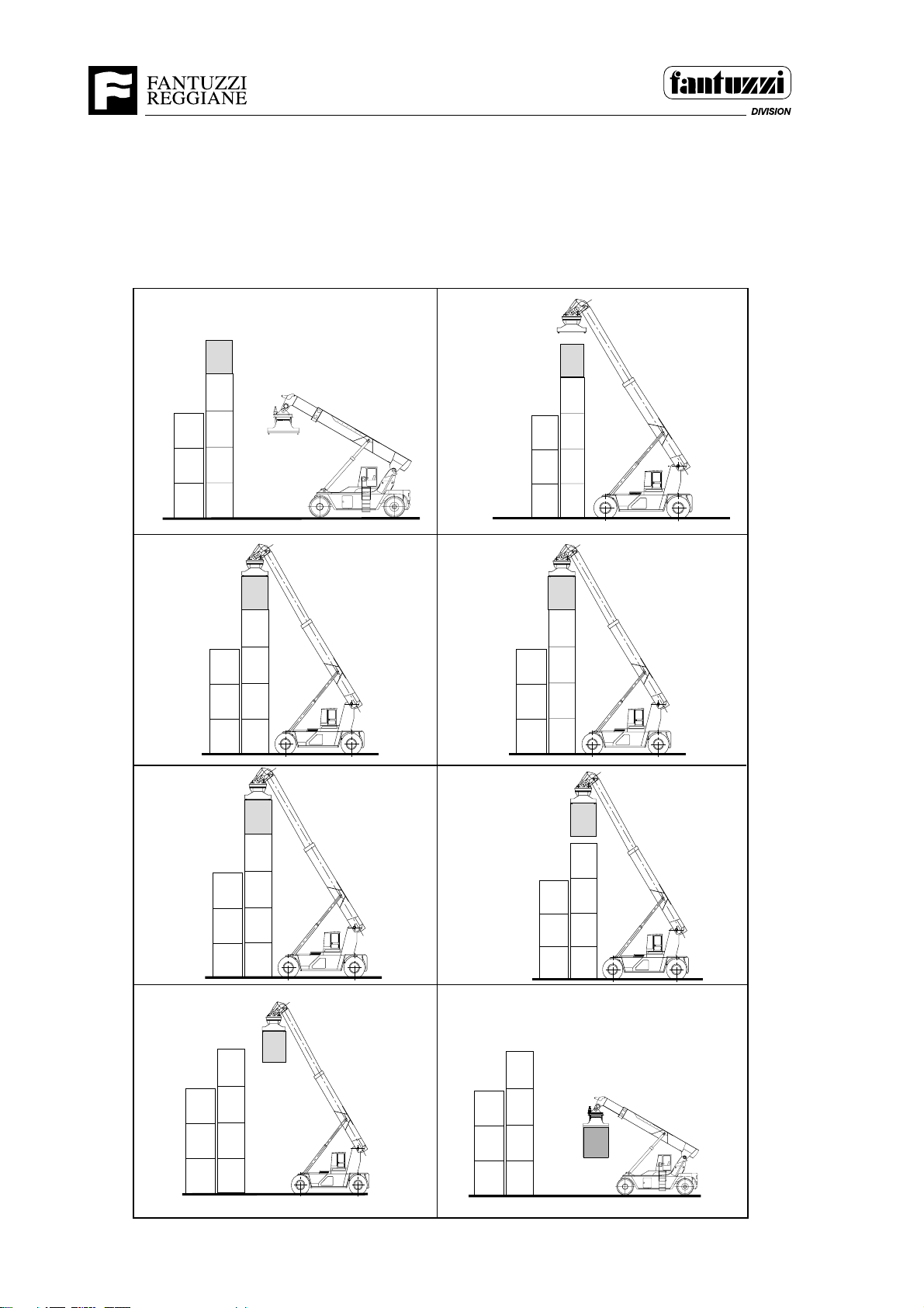
Operator’s Manual
Section 5 - Operating procedures
Picking up a stacked container
The numbers shown in the pictures correspond to the sequence of the procedure
described on the following page.
1
34
2
56
78
1200
5 - 26 OP05.0013
1200
Page 91

Operator’s Manual
Section 5 - Operating procedures
Procedure for picking up a stacked container
NOTE: Drive carefully when transporting loads. Avoid sudden braking and changes of
direction.
1. Move slowly up to the stack of containers
2. Position the spreader above the container to be picked up, making sure this is centred
with respect to the container.
3. Lower the spreader so the twistlocks correctly enter the container corner hook-on
housings.
4. If the twistlocks have entered properly, the yellow light comes on and the next
operation can be performed. Otherwise, lift the spreader and repeat operation no. 3.
5. Hook on the twistlocks. If this operation is done correctly, the green light comes on
and the next operation can be performed. Otherwise, release the twistlocks, slowly
raise the spreader and repeat the operations from point 3.
6. Slowly lift the container.
7. Back the truck up slowly without turning the wheels.
8. Lower the spreader, being careful not to collide with obstacles.
OP05.0013 5 - 27
Page 92
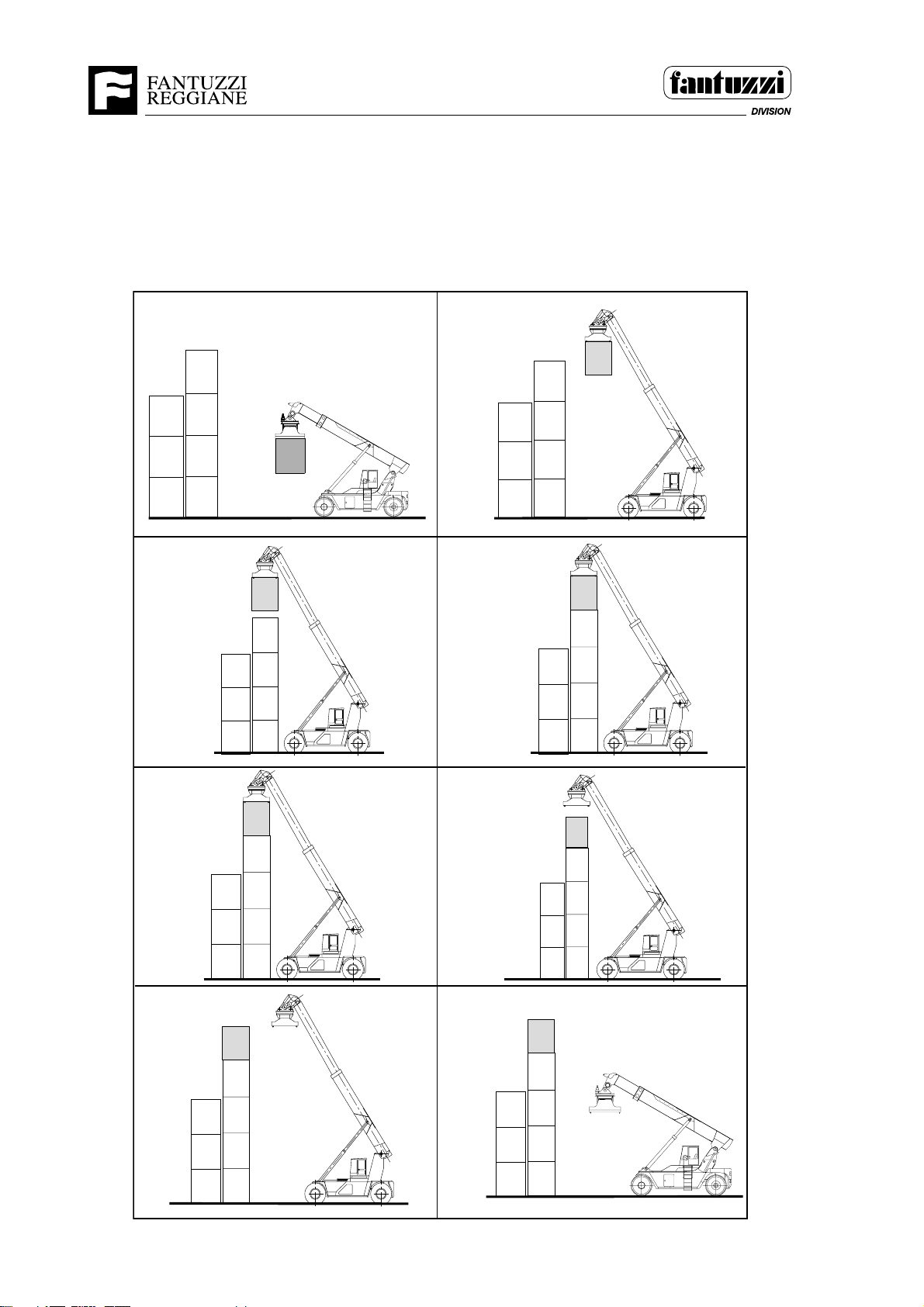
Operator’s Manual
Section 5 - Operating procedures
Stacking a container
The numbers shown in the pictures correspond to the sequence of the procedure
described on the following page.
1
34
2
56
78
1201
5 - 28 OP05.0013
1201
Page 93

Operator’s Manual
Section 5 - Operating procedures
Container stacking procedure
NOTE: Drive carefully when transporting loads. Avoid sudden braking and changes of
direction
1. Move slowly up to the container on which to place the load.
2. Lift the load above the container which will act as a support
3. Centre the load above the container.
4. Rest the load on the container. Wait for the yellow light to come on to check whether
the load is well supported and then proceed with the next operation. Otherwise, lift
the spreader and repeat the operation.
5. Release the twistlocks. Wait for the red light to come on to check whether all the
twistlocks have been actually released. Otherwise, hook the twistlocks back on, lift
the spreader and repeat the previous operation.
6. Slowly lift the spreader until the twistlocks have completely come out of the corner
housings.
7. Back the truck up slowly
8. Lower the spreader, being careful not to collide with obstacles.
SMT.0560.E00
OP05.0013 5 - 29
Page 94
PARKING PROCEDURES
NEVER leave the PACKER with a load suspended. It could
inadvertently lower, possibly causing serious injury or death.
SMT.0180.E00
Do not move the PACKER onto a surface or area that has
not been approved for the PACKER. The PACKER is heavy
and could possibly break through an insufficient surface,
causing damage to the machine or injury to personnel.
SMT.0182.E00
Operator’s Manual
Section 5 - Operating procedures
WARNING
WARNING
1. Remove all loads.
2. Move the machine to its designated parking area, away from the traffic lanes.
3. Apply the parking brake and lower the spreader.
4. Make sure all controls are in the NEUTRAL position and all electrical accessories
and lights are OFF.
5. Refer to “Stopping the Engine” procedures and turn the ignition switch to the
OFF position.
6. Report any maintenance or operational problems to qualified maintenance
personnel.
SMT.0179.E01
5 - 30 OP05.0013
Page 95
Operator’s Manual
Section 5 - Operating procedures
TOWING
IMPORTANT: Always contact our Technical Dept., for further details relating to
towing operations.
WARNING
Towing any machine without taking the proper prerequisite steps
could result in damage to equipment and possible personal
injury. SMT.0185.E00
If there is no alternative to machine towing, contact the Fantuzzi Technical Department
for assistance.
If the machine has to be towed, follow the instructions below.
Cause: Diesel engine fault (hydraulic braking, steering, lifting circuits, etc. not
functioning)
Remedy: Disconnect the Cardan shaft and release the parking brake caliper.
If the diesel engine is working, disconnect only the Cardan shaft.
SMT.0184.E01
WARNING
When operating this machine, if any abnormal condition in its
operation occurs, move the machine to a safe parking area, if
possible, and when safe to do so, shut down the machine and
notify appropriate maintenance personnel. SMT.0043.E00
OP05.0013 5 - 31
Page 96

Operator’s Manual
Section 5 - Operating procedures
NOTES
5 - 32 OP05.0013
Page 97

Operator's Manual
Section 6 - Warranty
GENERAL WARRANTY CONDITIONS
For the Customer’s Attention
SMT.GAR01.E00
This Warranty and Service Booklet is an important document that will help you get the
most from your fork-lift truck.
We strongly suggest that you read the attached Operating and Servicing Instructions
Manual before using your fork-lift.
If, through some oversight, you have not received the Manual and you would like a copy,
ask your local Dealer or Importer or order a copy directly from FANTUZZI-REGGIANE
S.p.A (the first copy is offered free of charge).
SMT.GAR01.E00
OP06.0001 6 - 1
Page 98

Operator's Manual
Section 6 - Warranty
NOTES
6 - 2 OP06.0001
Page 99

Operator's Manual
Section 6 - Warranty
INTERNATIONAL WARRANTY
INTRODUCTION
SMT.GAR02.E00
It is hereby certified that:
FANTUZZI REGGIANE S.p.A – 42040 Lentigione - Italia - warrants that the product(s)
is(are) free of defects caused by faulty material or bad workmanship, subject to the
conditions and limitations specified below.
FANTUZZI REGGIANE S.p.A has no obligation or liability in connection with any hidden
faults or defects in component parts which, even if produced by leading Italian or
international manufacturers, are not FANTUZZI REGGIANE S.p.A products; in such an
event however, FANTUZZI REGGIANE S.p.A will provide for the benefit of the warranty
supplied by the manufacturers of the component in question to be transferred to the
customer and will offer the user its full cooperation in applying the same.
PRODUCTION CHANGES
FANTUZZI REGGIANE S.p.A reserves the right to alter products manufactured and/or
sold at any time, without prior notice and without any obligation to modify or update
products already manufactured or sold.
WARRANTY PERIOD
The Warranty Period takes effect from the date of delivery to the first owner/user. The
date of delivery must be recorded clearly in the bottom right-hand corner of the
Registration Card.
This warranty becomes void if the Registration Card applying to the machine is not
returned, completed where applicable, within the prescribed period. The relevant
FANTUZZI REGGIANE S.p.A Importer, local Dealer or customer is responsible for
returning the Registration Card.
OP06.0001 6 - 3
Page 100

Operator's Manual
Section 6 - Warranty
Fork-lift trucks and Accessories.
The warranty is valid for the minimum term provided by the law. In countries where there
is no specific law on this subject or the law in force provides for shorter periods than those
set out below, the warranty period shall be treated as:
- Materials: 1 year or 2000 operating hours (whichever expires first)
- Labour: 1 year or 2000 operating hours (whichever expires first)
The warranty can be transferred to subsequent purchasers.
All parts and components replaced or repaired shall be covered for the remainder of the
warranty period CALCULATED AS TAKING EFFECT FROM THE DATE OF DELIVERY
OF THE ORIGINAL PART OR COMPONENTS.
In any event the warranty shall automatically expire 15 months after the date on which
the fork-lift leaves the FANTUZZI REGGIANE S.p.A factory for delivery to the customer.
Failure to follow the servicing instructions given in the Operating and Servicing Instructions
Manual supplied with the machine shall invalidate the warranty.
Maintenance operations must be carried out throughout the warranty period, by
personnel authorised by FANTUZZI REGGIANE S.p.A, unless otherwise directed by
FANTUZZI REGGIANE S.p.A.
TESTS PRIOR TO DELIVERY
All products are carefully tested before leaving the factory, to ensure that they conform
fully to specifications and to the standards set by the FANTUZZI REGGIANE S.p.A
Quality Control Dept.
6 - 4 OP06.0001
 Loading...