

FantiniCosmi P21, P22 Instructions For Use Manual

INSTRUCTIONS FOR USE
P21-P22
GAS LEAK DETECTORS
FOR METHANE AND LPG
Via dell’Osio, 6 20090 Caleppio di Settala, Milano - ITALY
Ph. +39 02 956821 | Fax +39 02 95307006 | info@fantinicosmi.it
FANTINI COSMI S.p.A.
www.fantinicosmi.it
Sicurgas P21 and P22 is a device that through
a sensitive sensor, detects natural gas
concentration (P21) and LPG concentration
(P22) in domestic environments. Sicurgas P21
and P22 triggers a PRE-ALARM when the gas
concentration in the air is much lower than
the lower explosive limit (LEL), immediately
switching on a red warning light and activating
a warning device (e.g. modem). If the pre-alarm
condition persists with consequent increase
in gas concentration with respect to the LEL,
Sicurgas goes into ALARM status, adding an
acoustic warning to the light signal.
Sicurgas simultaneously triggers a relay to
command a gas shut-off valve.
IT IS POSSIBLE TO SMELL GAS
BEFORE THE APPLIANCE TRIGGERS
THE ALARM.
The Sicurgas P21 and P22 gas detectors have FAILSAFE operation if connected to a normally closed
(NC) manually reset valve. This means that the gas
shut-off valve closes interrupting the outflow even
in case of a power failure.
For enhanced safety, several Sicurgas detectors
can be used, connected to the same gas shut-off
valve. For example P21 (P22) can be installed in
the room with the boiler and another in the kitchen
to control the stoves.
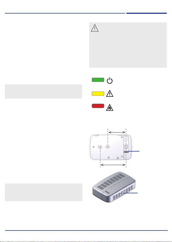
1 WALL FIXING
Sicurgas is supplied with a base suitable for
installation on recessed boxes with 3 modules or
on a round box. Unscrew the base-lid fixing screw
and turn the lid upwards.
Fix the base to the wall (see paragraph 3) or on
the recessed box and insert the connection cables
through the rear slot.
ATTENTION!
DO NOT TAMPER WITH THE APPLIANCE AS
THIS COULD CAUSE ELECTRICAL SHOCKS OR
MALFUNCTIONING
Sicurgas
INSTALLATION
ATTENTION
Installation of the gas detector does
not exempt from complying with all the rules
regarding the features, installation and use
of gas appliances, ventilation of rooms and
exhaust of combustion products described in
EN implementation standards of art. 3 of law
1083/71 and of national legislation in force.
Before installing the appliance, carefully read
this instruction booklet.
GREEN LED
appliance powered
YELLOW LED
detector faulty
RED LED
ALARM gas concentration
beyond alarm threshold
B 60 mm
A 83.5 mm
for 503 recessed boxes
A
with 3 Modules
for round recessed
B
boxes
knockout area
to increase the
space necessary
for wiring
fixing screw
base-lid
After fixing and connecting the appliance (see paragraph 4), refit the lid on the base, making sure that the
two teeth on the lid perfectly fit in the two upper guides. Retighten the fixing screw and apply the sticker in
the seat indicating the date of replacement.
2
GAS LEAK DETECTORS
max. 30 cm
min. 1 mt
max. 4 mt
GPL
max. 30 cm
min. 1 mt
max. 4 mt
FOR NATURAL GAS AND LPG
2
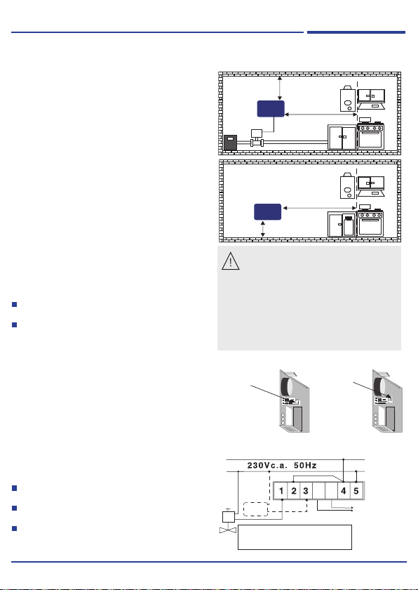
WHERE TO POSITION SICURGAS
Sicurgas P21 must be fixed to the wall,
approximately 30 cm from the ceiling and
between 1 and 4 metres from the gas appliance,
at a position which allows air to circulate
naturally.
Sicurgas P22 must be installed approximately 2
metres (minimum 1m, maximum 4m) from the gas
appliance and 30 cm from the ground.
3
ELECTRICAL CONNECTIONS
Sicurgas P21 already has two internal alarms: one
luminous and one acoustic.
Simply connect the 230Vac 50Hz power line to
terminals 4 and 5 to be able to warn the presence
of gas in the environment.
It is recommended to use a manually reset valve to
shut off the gas supply when an alarm is triggered.
The internal relay can command all types of
manually reset valves powered by the mains
voltage:
normally closed (NC), always powered, which
require a stable switching relay
normally open (NO), current starting, which
require a pulse relay.
The operating mode of the relay can be selected
upon installation, by moving a jumper (JP6)
on the printed circuit, normally supplied for
operation with stable relay for NC valves (jumper
down).
4
CONNECTION EXAMPLES
Example of connection with stable relay, always
powered to control a normally closed NC manually
reset valve (jumper down).
The connection provides the maximum safety,
shutting off the gas supply in case of:
the intended gas concentration threshold
being exceeded;
general power failure or only for the valve or
detector;
interrupted connection between detector and
valve.
Sicurgas
P21-P22
ATTENTION!
DO NOT install it behind or below cabinets
or shelves which obstruct the natural air
circulation in the environment.
DO NOT install it near aerators (minimum distance
2 m).
DO NOT install it right above the hob, sources of
steam in places which could be reached by water
sprays, near washbasins, etc.
DO NOT install it in environmental conditions other
than those indicated.
JUMPER JP6
PONTICELLO JP6
DOWN
IN BASSO
factory set
predisposto in
f
relé stabile per
valvole NC a riarmo
manuale
normalmente chiuse
(B)
abbrica
stable relay for
normally closed
NC manually reset
valves
L
N
possible
external
alarm
NC
To power the device, connect
terminals 4 - 5 to the 230V-50Hz
power line
JUMPER JP6
PONTICELLO JP6
UP
(A)
IN ALTO
pulse relay for
relé ad impulsi per
normally open NO
valvole NA a riarmo
manually reset
manuale
valves
normalmente aperte
6 7
consent for
PRE-ALARM
devices
3
 Loading...