

Fantini Cosmi CT3MA Instruction Manual
1
CT3MA - TELEPHONE ACTIVATOR WITH GSM
INSTRUCTION MANUAL
2
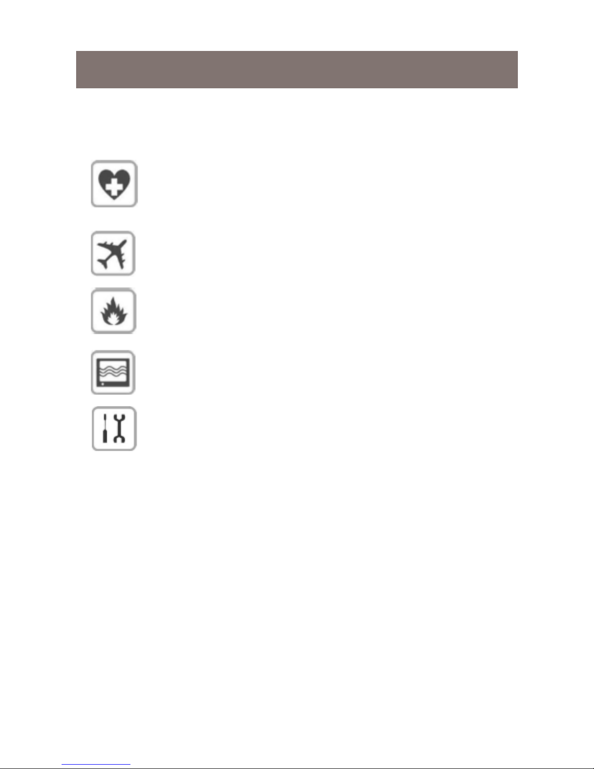
Use of radio devices close to electronic equipment may
be inadvisable:
Do not install CT3MA close to medical devices like pacemakers or hearing aids. CT3MA could interfere with the
regular operation of these devices.
Switch off CT3MA on planes. Make sure it cannot be
switched back on accidentally.
Do not install CT3MA near oil stations, fuel deposits,
chemical plants or explosive sites since CT3MA could
interfere with the operation of technical equipment.
CT3MA could generate interference if used near TVs,
radios or PCs.
In order to prevent possible damages, only use accesso-
ries tested and certied as compatible with CT3MA
Information contained in this manual can be modied
without prior notice.
Some of the terms used in this manual may be registered trademarks of other Companies and are mentioned
for explanatory purposes only, without any intention to
infringe the rights of the lawful owner.
Although the contents of this manual have been checked
thoroughly, Fantini Cosmi shall not be hold responsible
for damages or losses.
Safety Information

3
Safety Information
The use of CT3MA in life support systems or components is not allowed and, if required, it must be authorised beforehand in writing.
Life support systems are components or systems used to assist ar-
ticially the human body in its functions. In case of faulty operation,
these could cause injury to patients.
No complex hardware or software system can be considered perfect.
Faults can occur in systems of any kind.
To prevent damages to things and injuries to persons, it is up to the
designer to devise redundant protection methods, suitable for the
risk related to use.
Every CT3MA unit is submitted to complete functional testing.
Specications are based on the characterisation of the tested sample
unit and do not refer to measurements taken on each single manufactured unit.

4
Table of Contents
Product description ..........................................................................6
Operation ................................................................................... 7
External antenna ........................................................................7
Immunity against interference ....................................................7
CHARACTERISTICS .......................................................................8
Specications .............................................................................8
Connections ............................................................................... 8
Accessories ................................................................................8
Installation .......................................................................................9
Package contents .......................................................................9
Installation and safety information ..............................................9
Mounting .................................................................................... 9
External antenna ........................................................................9
Front view .................................................................................10
Wiring diagram .........................................................................10
SIM card ..................................................................................12
CT3MA connection to chronostats ...........................................13
Interface description .................................................................13
Connection description ..................................................................17
Input contacts ...........................................................................17

5
Table of Contents
Output contacts ............................................................ 18
Operating state / LED ........................................................ 19
Remote management ........................................................ 20
Using the SIM card ....................................................... 20
Standby ........................................................................ 20
Sending an alarm ......................................................... 20
Output status led .......................................................... 21
SMS Service Centre ..................................................... 21
Setting the SMS Services Centre ................................. 21
SMS commands ........................................................... 21
Chronostat commands ................................................. 21
Alarm commands ......................................................... 22
Alarm commands ......................................................... 23
Relay commands ......................................................... 23
Status response ........................................................... 24
Maintenance / Circuit diagram ........................................... 25
6
Product description
CT3MA is a GSM terminal suitable for remote control of heating sy-
stems, specially when no xed telephone line is provided.
CT3MA also enables to control two remote inputs and one output.
Communication is implemented via a mobile phone and the GSM
modem of the device using SMS messages.
CT3MA characteristics, functions and interfaces are described on
next pages.

7
Product description
Operation
When CT3MA is connected to a Fantini Cosmi chronostat model
C46A, C55-56, C51-52-53-54, C75CT-76CT, CH15X, via SMS messages it enables to read the chronostat status (ambient temperature
measured, programme set, etc.) to modify the set programme and to
change certain thermoregulation parameters (only for CH15X).
CT3MA can automatically send a SMS message to the phone number stored inside it when an alarm conditions occurs (due to contact
clo-sing/opening).
NOTE: different alarms can be controlled by setting them parallel
with each other.
External antenna
Connect dual band antenna (GSM900/1800) to RF interface available on CT3MAA model. Connection is obtained by connecting the
antenna to the SMA/F connector set on the top of the device.
Immunity against interference
Provide suitable protections against fast transients if the cable is longer than 3m

8
CHARACTERISTICS
Specications
Quad band
Output power:
Class 4 (2W) for
Class 1 (1W) for
Sensitivity
Power voltage:
Consumption
Operating temperature
* reduced sensitivity
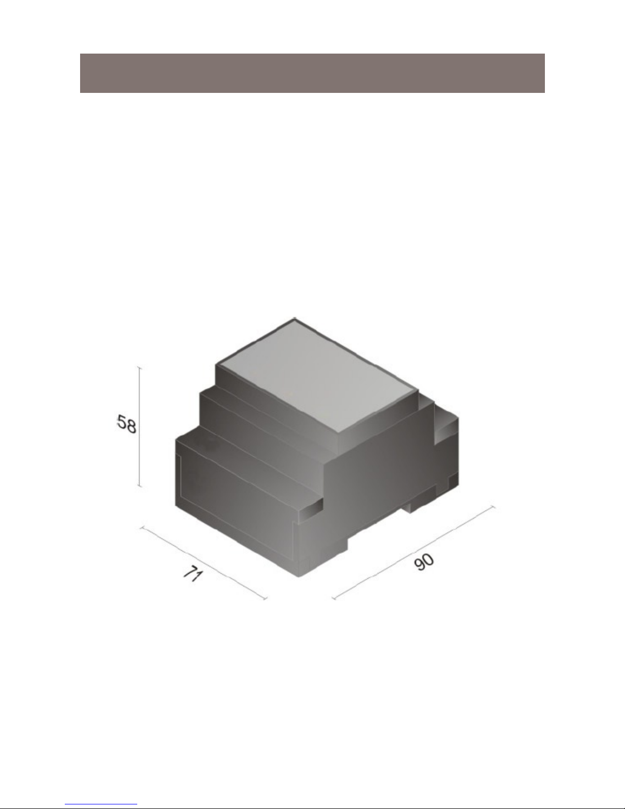
Rear wall mounting on EN 50022 rail, 4 modules
Approximate weight:
Protection EN 60529: IP40
(if installed properly)
Contact rating
Voltage-free contacts
Connections
Power supply connector
Input / Output connector
Accessories
Power supply unit / battery charger N70A
CTI46 - CTI5 - CTI5X connection interfaces for Fantini
Cosmi chronostats (See paragraph “INSTALLATION”,
pages 13 to 16)
Lead battery, rechargeable, external
Long-life lithium buffer battery, not rechargeable
 Loading...