

Page 1
1712 Northgate Blvd-Sarasota, FL. 34234
Phone: (800) 747-1762 Fax: (800) 487-9915
Phone: (941) 351-2947 Fax: (941) 359-3828
INSTALLATION & MAINTENANCE
INSTRUCTIONS
Web Site: www.fantech-us.com
Read and Save These Instructions !
DO NOT CONNECT POWER SUPPLY until fan is completely installed. Make
sure electrical service to the fan is locked in “OFF” position.
1. All units are suitable for use with solid-state speed control.
2. WARNING! TO REDUCE THE RISK OF FIRE, ELECTRIC SHOCK, OR
INJURY TO PERSONS--OBSER VE THE FOLLOWING:
a. Use this unit only in the manner intended by the manufacturer. If you
have any questions, contact your manufacturers representative.
b. CAUTION: Before installation, servicing or cleaning unit, switch power
off at service panel and lock the service disconnecting means to prevent
power from being switched on accidentally. When the service
disconnecting means cannot be locked, securely fasten a prominent
warningdevice, such as a tag, to the service panel.
c. Installation work and electrical wiring must be done by qualified
person(s) in accordance with all applicable codes and standards,
including fire-rated construction.
d. Sufficient air is needed for proper combustion and exhausting of gases
through the flue (chimney) of fuel burning equipment to prevent back
drafting. Follow the heating equipment manufacturer’s guideline and
safety standards such as those published by the National Fire Association
(NFP A), and the American Society for Heating Refrigeration and Air
Conditioning Engineers (ASHRAE), and the local code authorities.
e. When cutting or drilling into wall and ceiling, do not damage electrical
wiring and other hidden utilities.
f. Ducted fans must always be vented to the outdoors.
g. If this unit is to be installed over a tub or shower, it must be marked as
appropriate for the application and be connected to a GFCI (Ground
Fault Circuit Interrupter) - protected branch circuit.
h. NEVER place a switch where it can be reached from a tub or shower .
3. W ARNING! Check voltage at the fan to see if it corresponds to the motor
name plate.
INST ALLA TION
1. The compactness and adaptability of
2. Because this unit has rotating parts,
3. CAUTION: “For General Ventilation
4. Remove unit from package and
5. CAUTION: “This unit has an
6. Screen guards must be installed when
7. Install intake side of fan facing an
RE41999R
SERIES
RE
Models RE fans permit easy
installation. The fans are shipped fully
assembled and can be mounted at
any angle. For various mounting
see figures below.
safety precautions should be
exercised during phase of installation,
operation and maintenance.
Use Only. Do Not Use To Exhaust
Hazardous Or Explosive Material and
Vapors.”
inspect within 15 days after receipt.
If damaged, report damage to carrier.
Do Not operate this unit with visible
damage to the blower or impeller
assembly.
unguarded impeller. Do not use in
locations readily accessible to people or
animals.”
WEAR HAND PROTECTION
AND STAY CLEAR OF SHARP
EDGES.
fan will be within reach of personnel,
within (7) feet of the working area, or
when advisable for safety.
unoccupied space.
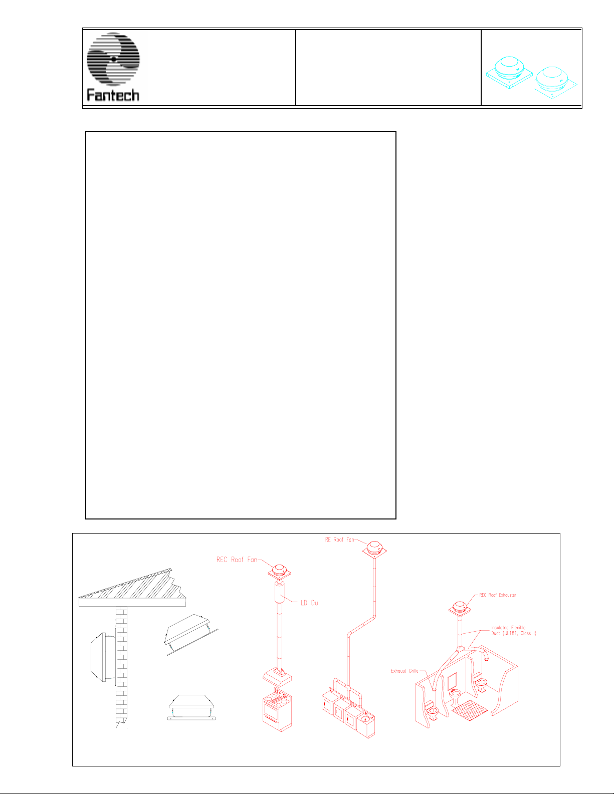
TYPICAL INSTALLATIONS
Pitched roof with flat base
Flat roof for curb mount
Wall mount
Range hood venting
Dryer venting
Bathroom venting
Page 2
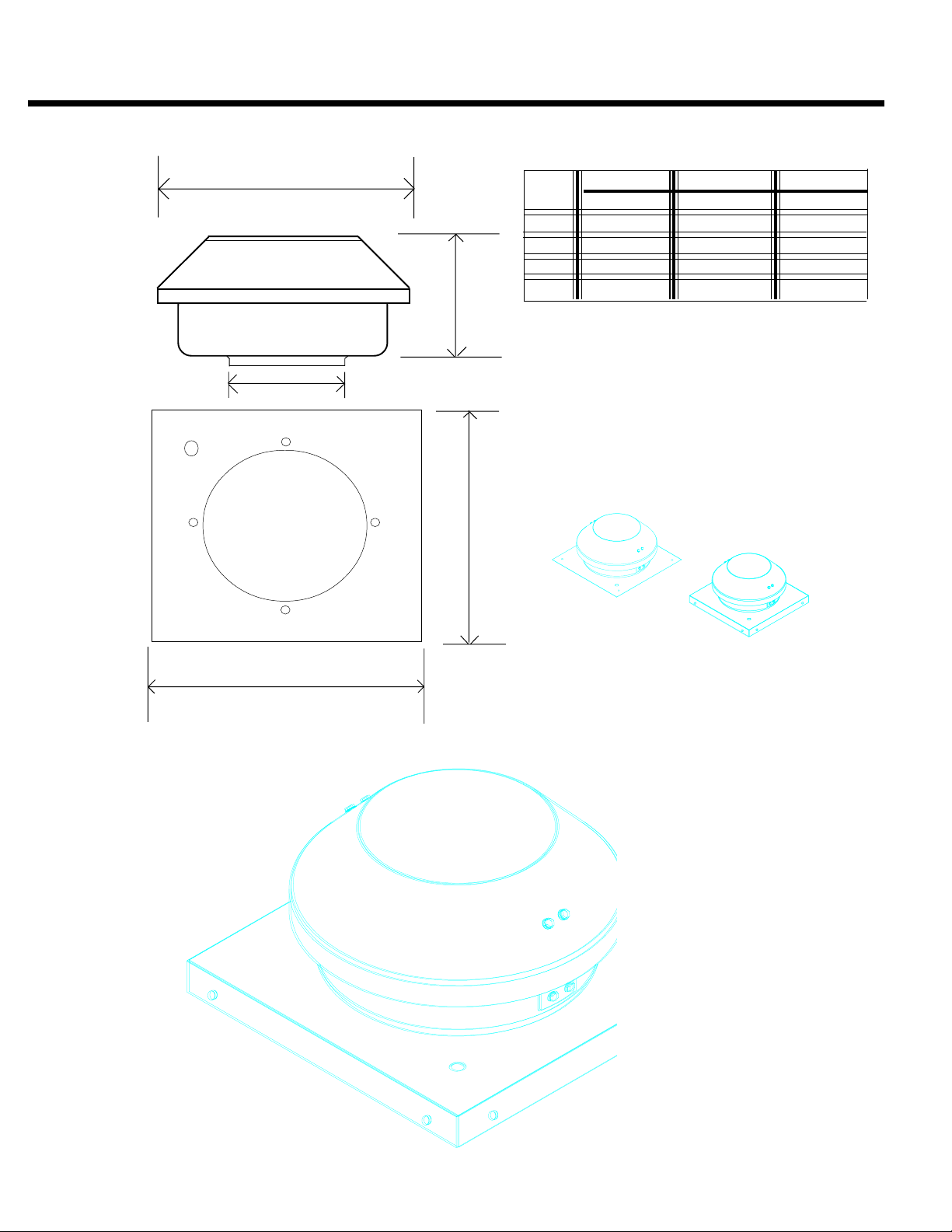
Dimensions
A
C
B
RE(C) 6 RE(C) 8XL RE(C) 10XL
A 13.07 15.75 19.76
B 6.50 6.00 1 1.75
C 6.00 8.00 10.00
D 15.50 20.00 20.00
E 15.50 20.00 20.00
**Dimensions in inches**
NOTES:
1. Add 1.5 inches to “B” when using curb.
2. All units provided with 7/8" knockout.
3. All units come with conduit and fittings.
D
Model RE
with flat base
Model REC
E
SPECIFIC INSTALLATION INSTRUCTIONS
Suitable sealing such as tar or similar material (not included) should be used to prevent leakage.
To prepare for installation, determine the size and type of ducting, if any, to be used. Make an
opening in the roof just large enough to accommodate ducting and electrical supply.
Flat Base Mounting
1. Base may be mounted directly on the deck beneath
roof shingles or upper edge of base plate may be slid
underneath shingles.
2. Securely screw or bolt base plate to roof through the
four corner mounting points.
3. Through the opening, attach ductwork to fan inlet
orifice by using Fantech FC clamps or duct tape.
4. Refer to wiring diagram in this guide to complete
electrical connections.
5. Once secured and wired, generously apply tar or
other sealant around edges of the base to prevent
leakage. Be sure to replace any lifted shingles.
Curb Mounting
1. Outside dimensions of flanged curb should be
approximately 3/8” smaller than the outside
dimension of base. Flanged curbs are available
from Fantech.
2. Center curb around roof opening and securely
attach to roof. It is advisable to put a bead of
sealant around the inside edge of curb.
3. Before mounting base on curb, place a layer of
sealant along the top edge of the curb.
4. Place unit on curb and securely attach with bolts
or screws.
( Continue installation by following items #3 through
#5 in previous instructions for Flat Base.)
for curb mounting
Page 3

For installations in which the fan is connected to a range hood, or if an exhaust grille connected to the fans is located above or near the
cooking surface, as shown below , be sure to observe the following safety warnings:
CAUTION
CEILING
○○○○○○○○
TO REDUCE THE RISK OF FIRE, USE ONLY METAL DUCTWORK.
COOKING AREA
45 45
COOKING
EQUIPMENT
FLOOR
OO
○○○○○○○○
(Note: If the fan is not connected to a range hood, or a grille in vicinity of the cooking
( Use only galvanized steel ductwork. )
Use only galvanized steel ductwork in accordance with all applicable codes.
surface, other approved ducting may be used.)
WARNING
TO REDUCE THE RISK OF A RANGE
TOP GREASE FIRE:
A. Never leave surface units unattended
B. Always turn hood on when cooking at
C. Clean ventilating fans frequently (if
D. Use proper pan size. Always use cook
WARNING
TO REDUCE THE RISK OF INJURY TO PERSONS IN THE EVENT OF A
RANGE TOP GREASE FIRE, OBSERVE THE FOLLOWING:
A. SMOTHER FLAMES with a close-fitting lid, cookie sheet, or metal tray , then turn
at high settings. Boilovers cause smoking
and greasy spillovers that may ignite. Heat
oils slowly on low or medium settings.
high heat or when cooking flaming foods.
accessible). Grease should not be allowed
to accumulate on fan or filter.
ware appropriate for the size of the suface
element.
off the burner . BE CAREFUL, TO PREVENT BURNS. If the flames do not go
out immediately EVACUA TE AND CALL THE FIRE DEP AR TMENT .
B. NEVER PICK UP A FLAMING P AN - You may be burned.
C. DO NOT USE WA TER, including wet dishcloths or towels - a violent steam
explosion will result.
D. Use an extinguisher ONL Y if:
1. Y ou know you have a Class ABC extinguisher , and you already know how to
operate it.
2. The fire is small and contained in the area where it started.
3. The fire department is being called.
4. You can fight the fire with your back to an exit.
WARNING
Page 4

WIRING DIAGRAMS
SPECIAL WIRING PRECAUTIONS
All installation should be wired according to the following diagrams. Failure to comply will cause the motor to “hum”
or not work.
1. Turn of f power at service entrance before wiring this fan.
2. Read the fan data plate to determine the current draw. Check that available supply is
suitable .
3. Remove top enclosure of fan and the wiring box lid. A 7/8” hole is provided for electrical
service entry . Use connectors and conduit provided.
4. Connect electrical supply inside wiring terminal per diagram below .
5. Replace wiring box lid and top enclosure.
WITH MOTOR SPEED CONTROL WITHOUT MOTOR SPEED CONTROL
MOTOR
SPEED
CAPACITOR
CONTROL
BROWN
BLACK BLACK
115V SUPPL Y
BLUE
MOTOR
WHITE
FIVE (5) YEAR WARRANTY
THIS WARRANTY SUPERSEDES ALL PRIOR W ARRANTIES
FANTECH, INC will repair or replace any part of your product that has a factory
defect in workmanship or material. Product must be returned to point of purchase,
with Bill of Sale, within five (5) years of purchase. If factory return is required, as
determined by rep/distributor, the warrantee assumes all cost to and from the factory.
THE FOLLOWING WARRANTIES DO NOT APPL Y :
a) To damages from shipping, either concealed or visible;
b) To damages resulting from improper wiring or installation;
c) To damages or failure caused by Acts ofGod, or resulting from improper consumer
procedures such as
1) improper maintenance,
2) misuse, abuse, abnormal use, or accident and
3) incorrect electricall voltage or current;
d) To removal of or any alteration to the Fantech label, control number or date
of manufacture;
e) To any other warranty, expressed, implied or written, and to any consequential or
incidental damages, loss of propert, revenues, or profit or costs of removal,
or reinstalltion, for any breach of warranty.
WARRANTY V ALIDA TION
The end user must keep a copy of the Bill of Sale to verify purchase date. Valid proof
of the date of installation may also serve as a verification of commencement of
warranty period.
CAP ACITOR
BROWN
BLACK BLACK
115V SUPPL Y
BLUE
MOTOR
WHITE
FANTECH RETURN POLICY
Claims for damages or shortages must be reported within ten (10) days of receipt of
product(s). For any product(s) received damaged by the forwarding agent, THE
FOLLOWING INSTRUCTIONS MUST BE FOLLOWED:
1) For product delivered by UPS:
a) Concealed Damages: Keep all cartons. Call UPS for an inspection and notify
Fantech immediately.
b) Visible Damages: Save all cartons and file complaint directly with UPS.
2) For product delivered via a common carrier: File damaged goods claim directly with
the freight company.
3) Shortages: Sign only for the total number of pieces received and call Fantech immediately.
FOR FACTOR Y RETURN
PRODUCT(S) RETURNED WITHOUT AUTHORIZATION WILL NOT BE ACCEPTED.
FANTECH WILL NOT ACCEPT THE RETURN OF ANY SPECIAL, NON-STOCK,
OBSOLETE OR UNSALABLE PRODUCT(S). FANTECH MA Y, AT ITS OPTION,
ACCEPT RETURN OF SALABLE PRODUCT(S) SUBJECT TO A 25% RESTOCKING CHARGE.
1) No product(s) will be accepted without a Return Materials Authorization (RMA) number.
This number can be obtained by calling Fantech, Inc. at 800-747-1762. Please have
have Bill of Sale or proof of date of installation available.
2) RMA must be clearly marked on outside of carton or delivery will be refused. All
product(s) must be returned freight prepaid.
3) Product(s) will be repaired/replaced and shipped back to buyer; no credit will be issued.
4) Any out of warranty product will be evaluated and buyer will be notified of cost; repair cost
will be charged to customer; buyer will be responsible for return freight or product may be
returned without action, to the buyer, freight collect. No credit will be issued.
This warranty does not apply to any FANTECH product or part which has failed as a result of faulty installation or abuse, incorrect electrical connections or alterations made by others, or use
under abnormal operating conditions or misapplication of the product or parts. We will not approve for payment any repair not made by us or our authorized agent without prior written consent.
The foregoing shall constitute our sole and exclusive warranty and our sole exclusive liabiltiy, and is in lieu of any other warranties, whether written, oral implied or statutory. There are no
warranties which extend beyond the description on the page hereof. In no event, whether as a result of breach of contract, or warranty or alleged negligence, defect incorrect advice or other
causes, shall FANTECH be liable for special or consequential damages, including, but not limited to, loss of profits or revenue, loss of use of equipment or any other associated equipment,
cost of capital, cost of substitute equipment, facilities or services, downtime costs, or claims of customers of purchase for such damages. FANTECH neither assumes or authorizes any
person to assume for it any other liability in connection with the sale of product(s) or part(s). Some jurisdictions do not allow the exclusion or limitation of incidental or consequential damages
so the above limitations and exclusions may not apply to you.
LIMITA TION OF W ARRANTY AND LIABILITY
WARNING
FANTECH, INC. products are designed and manufactured to provide reliable performance, but they are not guaranteed to be 100% free from defects. Even reliable products will experience
occasional failures and this possibility should be recognized by the user. If these products are used in a life support ventilation system where failure could result in loss or injury, the user should
provide adequate backup ventilation, supplementary natural ventilation, failure alarm system, or acknowledge willingness to accept the risk of such loss or injury.
 Loading...