

Page 1
IMPORTANT: PLEASE READ THIS MANUAL
BEFORE INSTALLING UNIT
PBW Series
Premium Bath Fans
7 YEAR
WARRANTY
Warnings
DO NOT CONNECT POWER SUPPLY until unit is completely installed. Make sure electrical service to the fan and light is locked in
“OFF” position.
WARNING! TO REDUCE THE RISK OF FIRE, ELECTRIC SHOCK, OR INJURY TO PERSONS – OBSERVE THE FOLLOWING:
a. Use this unit only in the manner intended by the manufacturer. If you have any questions, contact your manufacturer's representative.
b. CAUTION: Before installation, servicing or cleaning unit, switch power off at service panel and lock the service disconnecting means to prevent power from being
switched on accidentally. When the service disconnecting means cannot be locked, securely fasten a prominent warning device, such as tag, to the service panel.
c. Installation work and electrical wiring must be done by qualified person(s) in accordance with all applicable codes and standards. This unit is only for use in non-
fire-rated installations.
d. When cutting or drilling into wall and ceiling, do not damage electrical wiring and other hidden utilities.
e. NEVER place a switch where it can be reached from a tub or shower.
f. If this unit is installed over a tub or shower, it must be connected to a GFCI (Ground Fault Circuit Interrupter) – protected branch circuit.
g. The combustion airflow needed for safe operation of fuel burning equipment may be affected by this unit’s operation. Follow the heating equipment manufac-
turer’s guidelines and safety standards such as those published by the National Fire Protection association (NFPA), the American Society of Heating,
Refrigeration, and Air Conditioning Engineers (ASHRAE) and the local code authorities.
h. Exhaust fans must always be vented to the outdoors.
CAUTION: "FOR GENERAL VENTILATION USE ONLY. DO NOT USE TO EXHAUST HAZARDOUS OR EXPLOSIVE MA
CAUTION: BULB USED IN FLUORESCENT MODELS NOT DIMMABLE
CAUTION: USE ONLY TCP XR3014 BULBS IN FLUORESCENT MODELS AND PAR16 OR MR16 GU10 50W MAXIMUM IN HALOGEN MODELS
TERIAL AND VAPORS."
EXTERIOR WALL MOUNT BATH FAN MODELS
PBW110 • PBW110F • PBW110H
INSTALLATION, OPERATION AND MAINTENANCE MANUAL
Page 2
Exterior Wall Fan Installation
1. When selecting the fan mounting location, the following criteria should be considered:
a) With any exhaust system, the fan should be located a minimum of 6 feet
horizontally and 8 feet vertically from any fresh air intakes for HVAC systems, heat recovery systems, etc. to prevent re-entrainment of exhaust air
streams. Windows that are frequently opened during moderate seasons
may also be considered fresh air intakes.
b) Although system noise at the point of exhaust will be virtually silent, win-
dows and other structural openings may be sources for noise entry during
fan operation. Proximity to windows and openings should be considered.
Select the location on the exterior wall where the fan is to be mounted. Make a hole
through the wall that is 1/2” larger than the diameter of the fan duct connection collar. A short piece of rigid duct (not included) approximately 2” longer than the wall
thickness is recommended for use as an extension through the wall.
2. Remove the four screws securing the white fan discharge cover and remove the
cover. Place the fan against the wall, as centered as possible on the wall opening, then mark the location of the four backplate mounting holes and the electrical knockout. Drill a hole for the electrical service that is 1/8” larger than the
size of conduit to be used. A 1” diameter electrical service opening is provided
on the fan backplate (see dimensional drawing on Page 1). When mounting the
fan on a masonry wall, drill 7/32” holes for the four anchors and mounting
screws (provided). Tap the anchors flush into the holes. When mounting the fan
on a wood surface, wood screws should be used.
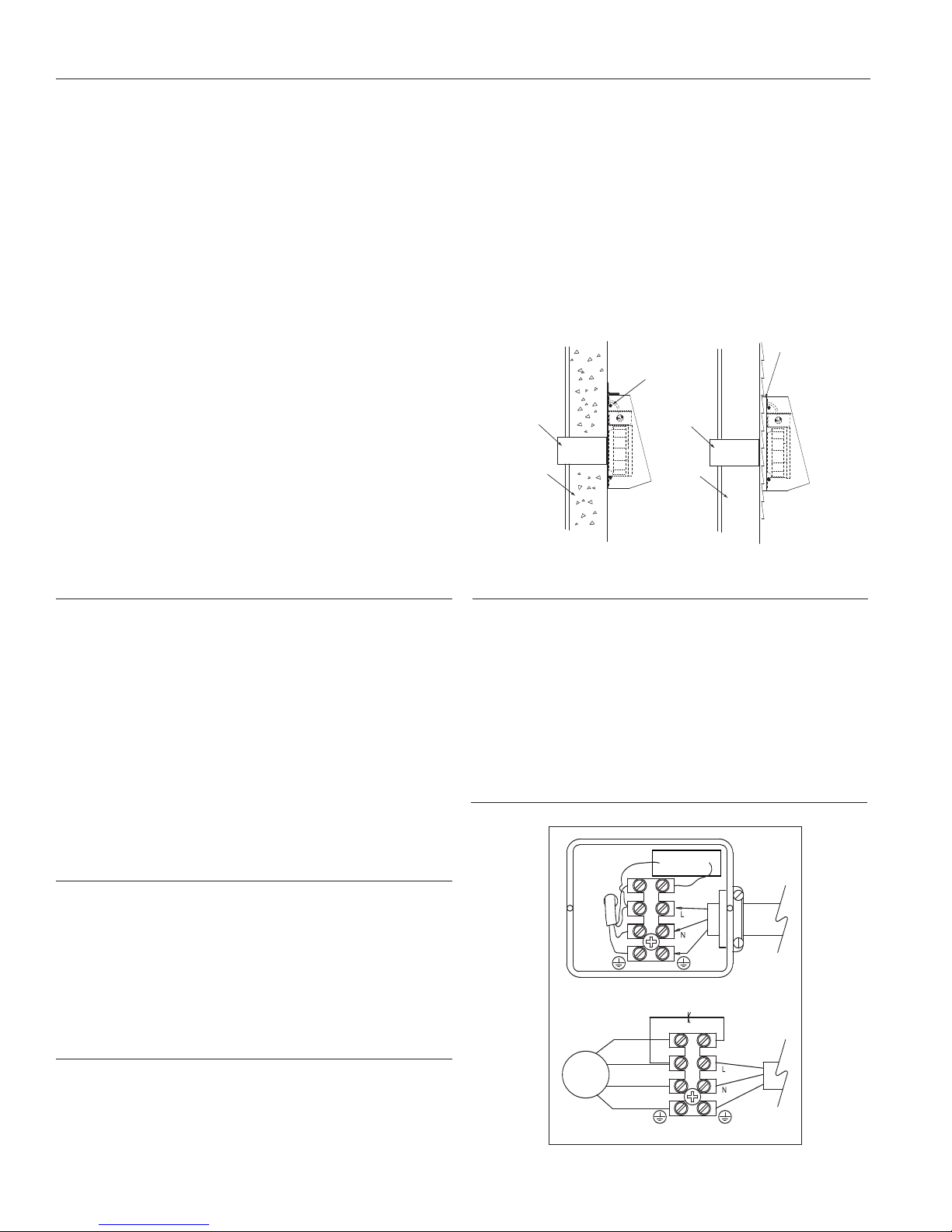
If the fan is to be mounted on a wall surface which is Lapped Siding, a mounting frame
made from 1x1 board may be necessary for a flush fit (see I-2).
3. Before mounting the fan, bring the electrical supply through the wall. Attach the
extension collar to the fan duct connection collar. The connection should be as
air tight as possible to prevent leakage from the wall cavity. Apply a generous
amount of polyurethane caulk to the exterior side of the fan housing backplate
(except the bottom so that water that leaked in can drain back out). This will
ensure an airtight/waterproof connection between the fan and the wall surface.
If a mounting frame is used in conjunction with lapped siding, be certain to apply
a generous amount of caulk between the frame and the wall as well as the fan
backplate and the frame. Mount the fan to the wall.
Be certain to make an airtight seal around all interior wall penetrations before attaching duct work.
FINAL INSTALLATION NOTE: If the fan is being mounted in a location where it is not
protected by an eve, it is highly recommended that a standard flashing be installed
and sealed against the wall and upper edge of the fan discharge cover to prevent rain
water running down the wall surface from entering the fan housing (see I-1).
Mounting
Frame
Discharge Cover
Mounting Screws
Extension Collar
through wall
Masonry Wall
Extension
Collar
Lap
Siding
Wall
Electrical Connection
1. Remove the screws securing the terminal box cover plate located on the
side of the fan. All fan motor connections are pre-wired to an electrical ter-
minal strip. A ³|₈" romex type cable restraint connector will be needed to
secure the wiring through the knockout provided on the side of the terminal
box.
2.
Bring incoming electrical service through the romex connector and the fan
knockout. Be sure to place the connector nut over the wiring coming into the
terminal box. There are two open ports on the terminal strip. Using a small
regular screwdriver, tighten the neutral (white) wire of the incoming supply
under the open terminal strip port labeled "N". Tighten the line (black) wire of
the incoming supply under the open terminal strip port labeled "L".
3. Secure the romex connector. Secure the incoming supply with the romex
connector. Replace the fan terminal box cover. All fan motor and capacitor
connections have been pre-wired from the factory. No additional fan wiring
is necessary.
Troubleshooting
If fan fails to operate, please check the following:
1. Consult wiring diagrams (at right) to ensure proper connection.
2. Check motor lead wiring, capacitor leads and incoming supply leads to
insure definite contact.
3. If possible, use a meter to test for continuity across the fan motor leads.
In order to do this, the capacitor must be disconnected (do not test the
capacitor - it will not meter continuity). If motor leads show continuity, consult factory for a replacement capacitor.
Maintenance Instructions
Since fan bearings are sealed and provided with an internal lubricating material,
no additional lubrication is necessary.
I-1 I-2
Flexible Duct Installation Hints
Flexible insulated duct is strongly recommended where allowed by local code for
bathroom exhaust applications, where ducting passes through unconditioned space
or where noise is a factor. Failure to use insulation could result in excessive condensation buildup within the duct, and undesirable sound levels within the room.
For the quietest possible installations, Fantech recommends a minimum of 8' of
insulated flexible duct between any inlet grille and fan. When using flexible type
duct work, duct should be stretched as tight and straight as possible. Failure to do
so could result in dramatic loss of system performance. Flexible duct should be
connected to the fan with plastic zip ties or duct tape. All connections should be
as airtight as possible to maximize system performance
Wiring Diagrams
Exterior Wall Mount
Motor
Leads
Capacitor
Ground
Capacitor
Brown
Black
Blue
Green/Yellow
115V
Supply
115V
Supply
Ground
2
I-4
Page 3

Installation of Ceiling Grille Housing With or Without Light
Step 1 - Select method for mounting the housing. The grille housing can be mounted in either of two ways; The housing can be screwed directly to the ceiling joist
through the key holes provided or the hanger bars can be used to locate the housing anywhere between two ceiling joists at up to 16" on center.
Step 2 - Select location for mounting ceiling grille . If the ceiling drywall is already
installed, cut a 6" round hole for the grille only and install the housing from the attic.
(Figure 1) Place the steel cabinet along the ceiling joist using the locator tabs to
determine the corr
3) Punch out the keyhole knockouts (if using) and the electrical knockout if needed.
Continue with steps 3 through 6 to continue installation of Premium Bath Fan models with lights. Otherwise skip to steps 4 and 5 to complete installation of models
without lights.
Step 3 - Make electrical connections to the ceiling grille housing. Remove the electrical cover inside the steel cabinet using a screwdriver. Connect power by following wiring diagram (Figure 4) and following local electrical codes or National
Electrical Code. Replace the electrical cover.
Step 4 - Secure the housing to the ceiling joists. Secure the housing to the ceiling
joists using either the keyholes on the steel cabinet or the hanger bars with the
wood screws provided. Ensure that once the dr
ing will be at the correct depth, using the locator tabs (Figure 2) or hanging bars
(Figure 3). If drywall or ceiling material is thicker than 5/8" the locator tabs may
be bent even with housing to allow the grille collar to be flush with the finished ceiling material.
Step 5 - Connect the fan to the housing. Install the 4" or 6" duct work from the fan
to the ceiling grille housing. Insulated flexible type duct work (recommended for all
Fantech bathroom exhaust applications) will result in much quieter operation.
Secure duct work in place and seal. If using Insulated flexible duct work, seal the
inner liner to the duct connector of the and then seal the outer shell over the top
of the inner liner
Step 6 - Installing the bulb. Install the bulb by gently inserting it into the socket
inside the steel cabinet. Install the grille by pushing it firmly into the steel collar
until it is shouldered by the ceiling drywall (Figure 3).
ect position (Figure 2) or align it using the hanger bars. (Figure
ywall is installed, the bath fan hous-
. Do not leave the insulation material exposed.
Figure 2
Figure 3
Fluorescent
Halogen
Repeat steps 1 through 6 for each additional ceiling grille housing being installed.
Figure 1
Figure 4
Electrical
3
Page 4

Seven (7) Year Warranty
DURING ENTIRE WARRANTY PERIOD:
FANTECH will repair or replace any part which has a factory defect in workmanship
or material. Product may need to be returned to the Fantech factory, together with
a copy of the bill of sale and identified with RMA number.
FOR FACTORY RETURN YOU MUST:
• Have a Return Materials Authorization (RMA) number
calling FANTECH either in the USA at 1.800.747.1762 or in CANADA at
1.800.565.3548. Please have bill of sale available.
• The RMA number must be clearly written on the outside of the carton, or the
carton will be refused.
• All parts and/or product will be repaired/replaced and shipped back to buyer; no
credit will be issued.
OR
The Distributor may place an order for the warranty part and/or product and is
invoiced. The Distributor will receive a credit equal to the invoice only after product
is returned prepaid and verified to be defective.
FANTECH WARRANTY TERMS DO NOT PROVIDE FOR REPLACEMENT WITHOUT
CHARGE PRIOR TO INSPECTION FOR A DEFECT.
REPLACEMENTS ISSUED IN ADVANCE OF DEFECT INSPECTION ARE INVOICED,
AND CREDIT IS PENDING INSPECTION OF RETURNED
MATERIAL. DEFECTIVE MATERIAL RETURNED BY END USERS SHOULD NOT BE
REPLACED BY THE DISTRIBUTOR WITHOUT CHARGE TO THE END USER, AS
CREDIT TO DISTRIBUTOR’S ACCOUNT WILL BE PENDING INSPECTION AND VERIFICATION OF ACTUAL DEFECT BY FANTECH.
THE FOLLOWING WARRANTIES DO NOT APPLY:
• Damages from shipping, either concealed or visible. Claim must be filed with
freight company.
• Damages resulting from improper wiring or installation.
• Damages or failure caused by acts of God, or resulting from improper consumer
procedures, such as:
1. Improper maintenance
2. Misuse, abuse, abnormal use, or accident, and
3. Incorrect electrical voltage or current.
• Removal or any alteration made on the FANTECH label control number or date of
manufacture.
• Any other warranty, expressed, implied or written, and to any consequential or
incidental damages, loss or property, revenues, or profit, or costs of removal,
installation or reinstallation, for any breach of warranty.
. This may be obtained by
Housing Dimensions
of 4" duct models
1 ³⁄₄"
(44mm)
6" (154mm)
7 ³⁄₃₂" (180mm)
Duct connections
are 1/8" smaller
than duct size
4" (122mm)
¹¹⁄₃₂"
(9mm)
Limitation of Warranty and Liability
This warranty does not apply to any FANTECH INC. product or part which has
failed as a result of faulty installation or abuse, incorrect electrical connections
or alterations made by others, or use under abnormal operating conditions or
misapplication of the product or parts. We will not approve for payment any
repair not made by us or our authorized agent without prior written consent. The
foregoing shall constitute our sole and exclusive warranty and our sole exclusive
liability, and is in lieu of any other warranties, whether written, oral, implied or
statutory. There are no warranties which extend beyond the description on the
page hereof. In no event, whether as a result of breach of contract, or warranty
or alleged negligence, defect incorrect advice or other causes, shall FANTECH be
liable for special or consequential damages, including, but not limited to, loss of
profits or revenue, loss of use of equipment or any other associated equipment,
cost of capital, cost of substitute equipment, facilities or services, downtime
costs, or claims of customers of purchase for such damages. FANTECH neither
assumes or authorizes any person to assume for it any other liability in connection with the sale of product(s) or part(s). Some jurisdictions do not allow the
exclusion or limitation of incidental or consequential damages so the above limitations and exclusions may not apply to you.
WARRANTY VALIDATION
• The user must keep a copy of the bill of sale to verify purchase date.
• These warranties give you specific legal rights, and are subject to an applicable
consumer protection legislation. You may have additional rights which vary from
state to state.
To purchase replacement bulbs please contact
Fantech Customer Support @ 800-747-1762
Warning
FANTECH, INC. products are designed and manufactured to provide reliable performance, but they are not guaranteed to be 100% free from defects. Even reliable
products will experience occasional failures and this possibility should be recognized by the user. If these products are used in a life support ventilation system where
failure could result in loss or injury, the user should provide adequate backup ventilation, supplementary natural ventilation, failure alarm system, or acknowledge willingness to accept the risk of such loss or injury.
United States
1712 Northgate Blvd.,
Sarasota, FL. 34234
Phone: 800.747.1762;
941.309.6000
Fax: 800.487.9915; 941.309.6099
www.fantech.net; info@fantech.net
Canada
50 Kanalflakt Way,
Bouctouche, NB E4S 3M5
Phone: 800.565.3548;
506.743.9500
Fax: 877.747.8116; 506.743.9600
www.fantech.ca; info@fantech.ca
Fantech, reserves the right to modify, at any time and without
notice, any or all of its products’ features, designs, components and
specifications to maintain their technological leadership position.
Item #: 801008
Rev Date: 11092006
 Loading...