

Fantech PBW100, PBW100F, PBW100H Installation, Operation And Maintenance Manual
INSTALLATION, OPERATION AND MAINTENANCE MANUAL
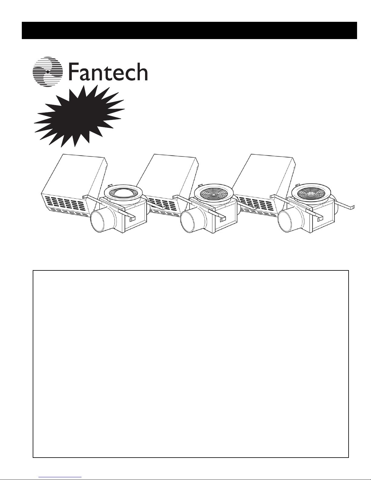
PBW Series
PREMIUM BATH FANS
Single Grille Units
4" Duct
PBW100
SEVEN-YEAR
WARRANTY
PBW100F
PBW100H
IMPORTANT: PLEASE READ THIS MANUAL BEFORE INSTALLING UNIT
WARNINGS:
WARNING! TO REDUCE THE RISK OF FIRE, ELECTRIC SHOCK, OR INJURY TO PERSONS –
a. Use this unit only in the manner intended by the manufacturer. If you have any questions, contact your
manufacturer's representative.
b. CAUTION: Before installation, servicing or cleaning unit, switch power off at service panel and lock the service
disconnecting means to prevent power from being switched on accidentally. When the service disconnecting
means cannot be locked, securely fasten a prominent warning device, such as tag, to the service panel.
c. Installation work and electrical wiring must be done by qualified person(s) in accordance with all applicable
codes and standards. This unit is only for use in non-fire-rated installations.
d. When cutting or drilling into wall and ceiling, do not damage electrical wiring and other hidden utilities.
e. NEVER place a switch where it can be reached from a tub or shower.
f. If this unit is installed over a tub or shower, it must be connected to a GFCI (Ground Fault Circuit Interrupter) –
protected branch circuit.
g. The combustion airflow needed for safe operation of fuel burning equipment may be affected by this unit’s
operation. Follow the heating equipment manufacturer’s guidelines and safety standards such as those
published by the National Fire Protection association (NFPA), the American Society of Heating, Refrigeration,
and Air Conditioning Engineers (ASHRAE) and the local code authorities.
h. Exhaust fans must always be vented to the outdoors.
CAUTION: "For General Ventilation Use Only. Do Not Use To Exhaust Hazardous Or Explosive Material and Vapors."
CAUTION: BULB USED IN FLUORESCENT MODELS NOT DIMMABLE
CAUTION: USE ONLY FANTECH (MODEL PBB14) FLUORESCENT BULBS AND
PAR16/MR16 GU10 50W MAX. HALOGEN BULBS (FANTECH MODEL PBB50).
DO NOT CONNECT POWER SUPPLY until unit is completely installed.
Make sure electrical service to the fan and light is locked in“OFF” position.
OBSERVE THE FOLLOWING:
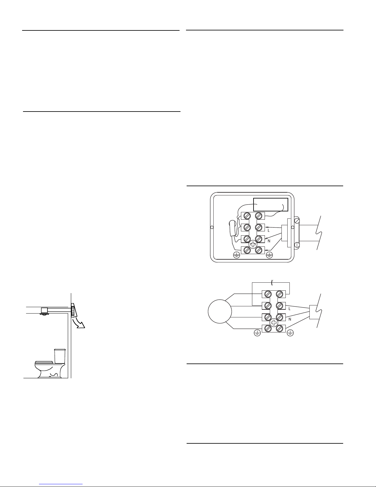
Planning Your Fan Location
As with any exhaust system, your exhaust fan should be located a
minimum of 6 feet horizontally and 8 feet vertically from any fresh air
intakes to prevent re-entrainment of exhaust air streams. For example
HVAC systems, heat recovery systems, and windows would all be
considered fresh air intakes.
When planning your fan placement keep in mind that you will need to
be able to run your duct work from the exterior fan to the bathroom
inlet. Considering access for the duct run before hand will make
installation easier.
Installing Exterior Wall Fan
1. Once you have chosen the location where you wish to mount the fan,
2. Take off the fan discharge cover by removing the four screws. Center
3. Bring your electrical supply through the wall. Attach the fan collar to
4. Mount the fan to the wall. Replace the discharge cover. Connect your
3
cut a 4
/8" diameter hole in the exterior of the wall. Prepare a piece
of rigid duct (purchase separately) approximately 2" longer than the
wall thickness. This will be used as a collar extension placed through
the wall.
the fan in the hole that was cut into the wall. Mark the locations of
the mounting holes and electrical knockout. Drill a hole for the
electrical that is
1
/8" larger than the conduit being used. A 1"
electrical service opening is provided on the fan backplate.
NOTE: When mounting the fan to a masonry wall, drill
7
/32" holes for
the four anchors and mounting screws (provided). Anchors should be
flush with the edge of the holes. For mounting to wood surfaces use
wood screws (purchased separately).
the extension collar using duct tape. Be sure this connection is as
airtight as possible to prevent leakage. Apply polyurethane caulk to
the exterior of fan housing backplate, leaving bottom uncaulked for
drainage. This will ensure an airtight/waterproof connection between
the fan and wall.
NOTE: If installing on lapped siding it may be necessary to use a
mounting frame made from 1x1 board to insure a flush fit.
ducting to the extension collar using plastic ties or duct tape
(purchased separately).
FINAL INSTALLATION NOTE: If fan location
is not protected by an eve, a standard
flashing should be installed. Seal against
the wall and upper edge of the fan
discharge cover to prevent rain water
from entering fan housing.
Fantech recommends insulated flexible
duct for all bathroom exhaust applications.
Electrical Connection
1. Remove the screws securing the terminal box cover located on the
fan motor mounting bracket. All fan motor and capacitor connections
are pre-wired to an electrical terminal strip. A
3
⁄8" romex type cable
restraint connector will be needed to secure the wiring through the
knockout on the side of the terminal box.
2. Bring incoming electrical service through the romex connector and the
fan electrical service opening. Be sure to place the connector nut over
the wiring coming into the terminal box. There are two open ports on
the terminal strip. Using a small regular screwdriver, tighten the neutral
(white) wire of the incoming supply under the open terminal strip port
labeled “N”. Tighten the line (black) wire of the incoming supply under
the open terminal strip port labeled “L” to the ground connection on the
terminal block.
3. Secure the romex connector. Secure the incoming supply with the
romex connector. Place the capacitor back into the terminal box.
Replace the fan terminal box cover.
All fan motor and capacitor connections have been pre-wired from
the factory. No additional fan wiring is necessary.
Wiring Diagrams
Capacitor
115V
Supply
Ground
Capacitor
Ground
115V
Supply
Motor
Leads
Brown
Black
Blue
Green/Yellow
Flexible Duct Installation Hints
Fantech strongly recommends the use of flexible insulated duct where
ducting passes through unconditioned space or where noise is a factor.
Check local code requirements before installing. Failure to use insulated
flexible duct could result in excessive condensation buildup within the
duct, and undesirable sound levels within the room.
A minimum of 8' of insulated flexible duct is recommended between
the fan and any inlet grille. Duct should be stretched as tight and straight
as possible. Failure to do so could result in dramatic loss of system
performance. Connect flex duct to the fan with plastic zip ties or duct tape.
Connections should be airtight as possible for maximize performance.
Troubleshooting
If fan fails to operate, please check the following:
1. Consult wiring diagrams (above) to ensure proper connection.
2. Check motor lead wiring, capacitor leads and incoming supply leads
to insure definite contact.
3. If possible, use a meter to test for continuity across the fan motor
leads. In order to do this, the capacitor must be disconnected (do
not test the capacitor - it will not meter continuity). If motor leads
show continuity, consult factory for a replacement capacitor.
Maintenance Instructions
Since fan bearings are sealed and provided with an internal lubricating
material, no additional lubrication is necessary.
 Loading...