

Fantech PBF4, PBH4, PBV4, PBV6 Installation, Operation And Maintenance Manual
INSTALLATION, OPERATION AND MAINTENANCE MANUAL
MANUEL D’INSTALLATION, D’OPÉRATION ET D’ENTRETIEN
MANUAL DE INSTALACIÓN, FUNCIONAMIENTO Y MANTENIMIENTO
PB Series • Série PB • Serie PB
MODEL PB CEILING GRILLES
GRILLES POUR PLAFOND MODÈLE PB
year/ans/años
WARRANTY•GARANTIE
7
GARANTIÁ
IMPORTANT: PLEASE READ THIS MANUAL BEFORE INSTALLING UNIT
IMPORTANT : VEUILLEZ LIRE CE MANUEL AVANT L’INSTALLATION
IMPORTANTE: FAVOR DE LEER ESTE MANUAL ANTES DE INSTALAR LA UNIDAD
WARNINGS:
DO NOT CONNECT POWER SUPPLY until unit is
completely installed. Make sure electrical service to the fan and
light is locked in“OFF” position.
WARNING! TO REDUCE THE RISK OF FIRE, ELECTRIC SHOCK,
OR INJURY TO PERSONS – OBSERVE THE FOLLOWING:
a. Use this unit only in the manner intended by the manufacturer. If
you have any questions, contact your manufacturer's
representative.
b. CAUTION: Before installation, servicing or cleaning unit, switch
power off at service panel and lock the service disconnecting
means to prevent power from being switched on accidentally.
When the service disconnecting means cannot be locked,
securely fasten a prominent warning device, such as tag, to the
service panel.
c. Installation work and electrical wiring must be done by qualified
person(s) in accordance with all applicable codes and standards.
This unit is only for use in non-fire-rated installations.
d. When cutting or drilling into wall and ceiling, do not damage
electrical wiring and other hidden utilities.
e. NEVER place a switch where it can be reached from a tub or
shower.
f. If this unit is installed over a tub or shower, it must be
connected to a GFCI (Ground Fault Circuit Interrupter) –
protected branch circuit.
g. The combustion airflow needed for safe operation of fuel burning
equipment may be affected by this unit’s operation. Follow the
heating equipment manufacturer’s guidelines and safety
standards such as those published by the National Fire
Protection association (NFPA), the American Society of Heating,
Refrigeration, and Air Conditioning Engineers (ASHRAE) and the
local code authorities.
h. Exhaust fans must always be vented to the outdoors.
CAUTION: "For General Ventilation Use Only. Do Not Use T
Exhaust Hazardous Or Explosive Material and Vapors."
CAUTION: BULB USED IN FLUORESCENT MODELS NOT DIMMABLE
CAUTION: USE ONLY FANTECH (MODEL PBB14) FLUORESCENT
BULBS AND P
BULBS (FANTECH MODEL PBB50).
AR16/MR16 GU10 50W MAX. HALOGEN
o
AVERTISSMENTS :
l’appareil soit complètement installé. Assurez-vous que le courant
électrique au ventilateur et lumière soit débranché « OFF ».
AVERTISSEMENT! POUR RÉDUIRE LE RISQUE D’INCENDIE,
L’ÉLECTROCUTION OU LES BLESSURES CORPORELLES – SUIVEZ LES
INSTRUCTIONS SUIVANTES :
a. Utilisez cet appareil conformément aux spécifications du fabriquant. Si
vous avez des questions, contactez votre représentant.
b. ATTENTION : Avant d’installer, d’entretenir ou de nettoyer l’appareil,
coupez le courant au paneau électrique et vérouillez le service électrique
afin de prévenir que le courant soit branché accidentellement. S’il est
impossible de vérouiller le courant électrique, attachez un mécanisme
d’avertissement au panneau électrique de façon visible. (Tel qu’un tag)
c. Les travaux d’installation et le raccordement électrique doivent être
effectués par une personne qualifiée, conformément aux codes et
normes de construction. Cet appareil n’est pas conçu pour être exposé
à de hautes températures.
d. Lorsque vous coupez ou perforez un mur ou un plafond, assurez-vous de
ne pas endommager les fils électriques ou toute autre installation.
e. NE JAMAIS placer un interrupteur pouvant être atteint de la baignoire
ou de la douche.
f. Si l’appareil est installé au-dessus d’une baignoire ou d’une douche, il
doit être branché dans une prise avec une mise à terre GFCI.
g. Le flux d'air à combustion requis pour l'opération sécuritaire de
l'équipement à carburant peut être affecté par l'opération de cet
appareil. Suivez les directives de l’équipement de chauffage du
fabriquant et les normes de sécurité dont celles publiées par le «
National Fire Protection Association (NFPA) », le « American Society of
Heating, Refrigeration, and Air Conditioning Engineers (ASHRAE) » ainsi
que les codes de votre région.
h. Les ventilateurs à évacuation doivent toujours évacuer à l'extérieur de
votre maison.
ATTENTION : Pour usage de ventilation résidentielle seulement. Ne pas
utiliser pour évacuer des matériaux et vapeurs dangereux ou explosifs.
ATTENTION : LES AMPOULES UTILISÉES DANS LES MODÈLES
FLUORESCENTS NE SONT PAS RÉGLABLES.
ATTENTION : UTILISEZ SEULEMENT LES AMPOULES « TCP XR3014 B »
POUR LES MODÈLES FLUORESCENTS ET LES AMPOULES « P
POUR LES MODÈLES HALOGÈNES.
REJA DE TECHNO MODELO PB
PBF4, PBH4, PBV4 & PBV6
NE PAS BRANCHER LE COURANT ÉLECTRIQUE avant que
AR 16 »
ADVERTENCIAS:
unidad quede totalmente instalada. Asegúrese de que el servicio eléctrico
del ventilador y la luz esté bloqueado en posición de “OFF” (apagado).
¡ADVERTENCIA! A FIN DE REDUCIR EL RIESGO DE INCENDIO, DESCARGA
ELÉCTRICA, O LESIONES A PERSONAS – OBSERVE LO SIGUIENTE:
a. Use esta unidad únicamente de la manera prevista por el fabricante. Si
b. PRECAUCIÓN: Antes de la instalación, mantenimiento o limpieza de
c. El trabajo de instalación y el cableado eléctrico deben ser realizados
d. Al hacer cortes o perforaciones en paredes o techos, no dañe los
e. NUNCA instale un interruptor donde pueda ser alcanzado desde una
f. Si esta unidad se instala sobre una tina o ducha, debe conectarse a
g. El caudal de aire de combustión necesario para el funcionamiento
h. La salida de los ventiladores de escape siempre debe estar orientada
PRECAUCIÓN: "Exclusivo para uso de ventilación general. No utilizar para
el escape de materiales y vapores peligrosos o
PRECAUCIÓN: LA BOMBILLA UTILIZADA EN LOS MODELOS
FLUORESCENTES NO ES ATENUABLE
PRECAUCIÓN: UTILICE SOLAMENTE FOCOS FLUORESCENTES FANTECH
(MODELO PBB14) Y FOCOS DE HALÓGENO PAR16/MR16 GU10 DE UN
MÁXIMO DE 50 W (MODELO FANTECH PBB50).
NO CONECTE LA ALIMENTACIÓN ELÉCTRICA hasta que la
tiene alguna duda, comuníquese con el representante del fabricante.
la unidad, desconecte la electricidad en el panel de servicio y bloquee
el medio de desconexión del servicio para impedir la conexión
accidental de la corriente. Cuando no se pueda bloquear el medio de
desconexión del servicio, sujete en el panel de servicio, y de manera
segura, un dispositivo de advertencia a la vista de todos.
por personal competente de conformidad con todos los códigos y
normas pertinentes. Esta unidad es para uso exclusivo en
instalaciones no clasificadas para incendios.
cables eléctricos ni otros dispositivos de servicios ocultos.
tina o ducha.
un circuito de derivación protegido GFCI (interruptor accionado por
corriente de pérdida a tierra).
seguro de equipo de combustión podría ser afectado por el
funcionamiento de esta unidad. Siga las directrices del fabricante del
equipo de calefacción y las normas de seguridad como las que publica
la National Fire Protection association - NFPA (Asociación Nacional de
Protección contra Incendios), la American Society of Heating,
Refrigeration, and Air Conditioning Engineers – ASHRAE (Sociedad
Estadounidense de Ingenieros de Calefacción, Refrigeración y Aire
Acondicionado) y los códigos de las autoridades locales.
hacia el exterior.
explosivos."
Installation of Ceiling Grille Housing With or Without Light
1. Plan Location of Inlet Grilles.
Based on the bathroom layout and fixtures, plan the location of the ceiling
grilles for the most effective ventilation.
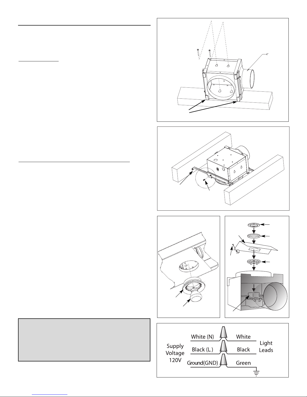
2. Securing the Housing to the Ceiling Joists.
NEW CONSTRUCTION
Mount housing directly to the ceiling joist using screws and keyhole slots.
Locator tabs on housing should be flush with the bottom edge of the ceiling
joist for correct positioning of the unit once drywall is installed.
(Figure 1)
OR
Use the hanger bars to suspend the housing between ceiling joists. For
correct positioning, hanger bars should be positioned
bottom edge of the ceiling joist on models with 4" duct connection and 15⁄32"
up from bottom edge of joist on models with 6" duct connection. On
models with 4” duct, tighten anti-slide screws to keep hanger bars in
place. (Figure 2).
Note: Hanger bars on units with 4" duct connection can be used on ceiling
joists up to 24" on center. Hanger bars on units with 6" duct connection
span ceiling joists up to 16" on center.
Note: If drywall or ceiling material is thicker than
be removed to allow the grille collar to be flush with the finished ceiling
material. When ceiling drywall is being installed, cut hole for ceiling grille.
EXISTING CONSTRUCTION OR WHEN DR
YWALL IS IN PLACE.
Cut a 6" round hole for the ceiling grille only and install the housing from
the attic. (Figure 3)
Place the housing against the ceiling joist using the locator tabs to
determine the correct position (Figure 1) or align it using the hanger bars.
(Figure 2).
Punch out the keyhole knockouts (if using) and the electrical knockout if
needed.
To complete installation for Bath Fan models with lights, continue with
steps 3 through 5. For models without lights, skip to steps 4 and 5.
3
⁄16" up from the
5
⁄8" the locator tabs may
Figure 1
Postion Locator Tabs
flush with bottom
edge of joist
Figure 2
Housings with 4”
duct: 3/16” from
bottom edge of
joist.
Housings with 6”
duct: 15/32”
Anti-slide
locking screw
on models with
4” duct.
3. Make Electrical Connections to the Ceiling Grille Housing.
Remove the electrical cover inside the steel housing using a screwdriver.
Connect power by following wiring diagram (Figure 5) and following local
or National Electrical Codes. Replace the electrical cover.
4. Connect the Fan to the Ceiling Grille Housing(s). Install
appropriate diameter duct from the fan to the ceiling grille housing.
(Insulated flexible duct is recommended for all Fantech bathroom exhaust
applications for quieter operation.) For dual grille models, install duct
between fan and wye adapter* (included). Then, attach duct to each leg of
the wye and to each ceiling grille housing. Secure duct in place and seal.
If using insulated flexible duct, seal the inner liner to the duct connector
then seal the outer shell over the top of the inner liner. Do not leave the
insulation material exposed.
5. Installing the Bulb. Install the bulb by gently inserting it into the
socket in the grille housing. Install the grille by pushing it firmly into the
steel collar until it is shouldered by the ceiling drywall (Figure 3).
ADDITIONAL STEPS REQUIRED WHEN INSTALLING A FLUORESCENT
MODEL OVER A TUB OR SHOWER.
(Figure 4)
1. Place ring 1 on on socket legs first.
2. Screw metal shield in place over socket.
3. Add rubber gasket
4. Secure ring 2 to socket. Click indicates a secure installation.
Repeat steps 1 through 5 for each additional ceiling grille housing being installed.
*For most efficient operation wye adapter should be positioned the equivalent of
three duct diameters away from the fan inlet.
Figure 3
Grille
Fluorescent
lamp
Figure 5
Figure 4
Shield
Screw
Socket
Ring 2
Gasket
Ring 1
Electrical
2
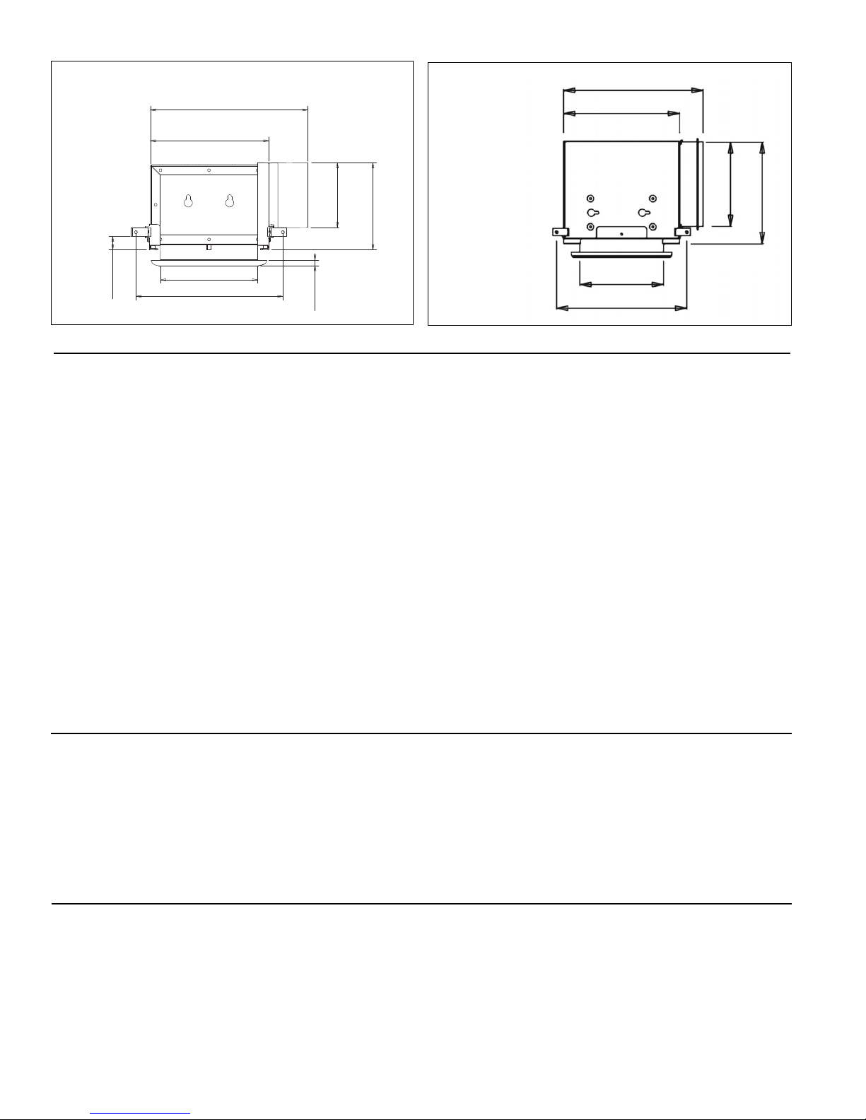
Housing Dimensions
of 4" duct models
99⁄16" (243mm)
73⁄16" (182.5mm)
Housing Dimensions
of 6" duct models
4" (102mm)
⁄16" (134mm)
5
5
911⁄16" (246mm)
8" (205mm)
6" (150mm)
⁄4" (438mm)
1
17
513⁄16" (148mm)
⁄16" (21mm)
13
815⁄16" (227mm)
⁄16" (8mm)
5
513⁄16" (148mm)
9" (230mm)
Seven (7) Year Warranty
DURING ENTIRE WARRANTY PERIOD:
FANTECH will repair or replace any part which has a factory defect in
workmanship or material. Product may need to be returned to the Fantech
factory, together with a copy of the bill of sale and identified with RMA number.
FOR FACTORY RETURN YOU MUST:
• Have a Return Materials Authorization (RMA) number. This may be obtained
by calling FANTECH either in the USA at 1.800.747.1762 or in CANADA at
1.800.565.3548. Please have bill of sale available.
• The RMA number must be clearly written on the outside of the carton, or the
carton will be refused.
• All parts and/or product will be repaired/replaced and shipped back to buyer;
no credit will be issued.
OR
The Distributor may place an order for the warranty part and/or product and is
invoiced. The Distributor will receive a credit equal to the invoice only after
product is returned prepaid and verified to be defective.
FANTECH WARRANTY TERMS DO NOT PROVIDE FOR REPLACEMENT WITHOUT
CHARGE PRIOR TO INSPECTION FOR A DEFECT. REPLACEMENTS ISSUED IN
ADVANCE OF DEFECT INSPECTION ARE INVOICED, AND CREDIT IS PENDING
INSPECTION OF RETURNED MATERIAL. DEFECTIVE MATERIAL RETURNED BY END
USERS SHOULD NOT BE REPLACED BY THE DISTRIBUTOR WITHOUT CHARGE TO
THE END USER, AS CREDIT TO DISTRIBUTOR’S ACCOUNT WILL BE PENDING
INSPECTION AND VERIFICATION OF ACTUAL DEFECT BY FANTECH.
THE FOLLOWING WARRANTIES DO NOT APPLY:
• Damages from shipping, either concealed or visible. Claim must be filed
with freight company.
• Damages resulting from improper wiring or installation.
• Damages or failure caused by acts of God, or resulting from improper
consumer procedures, such as:
1. Improper maintenance
2. Misuse, abuse, abnormal use, or accident, and
3. Incorrect electrical voltage or current.
• Removal or any alteration made on the FANTECH label control number
or date of manufacture.
• Any other warranty, expressed, implied or written, and to any consequential
or incidental damages, loss or property, revenues, or profit, or costs of
removal, installation or reinstallation, for any breach of warranty.
WARRANTY VALIDATION
• The user must keep a copy of the bill of sale to verify purchase date.
• These warranties give you specific legal rights, and are subject to an applicable
consumer protection legislation. You may have additional rights which vary from
state to state.
Limitation of Warranty and Liability
This warranty does not apply to any FANTECH INC. product or part which has failed as a result of faulty installation or abuse, incorrect electrical
connections or alterations made by others, or use under abnormal operating conditions or misapplication of the product or parts. We will not
approve for payment any repair not made by us or our authorized agent without prior written consent. The foregoing shall constitute our sole and
exclusive warranty and our sole exclusive liability, and is in lieu of any other warranties, whether written, oral, implied or statutory. There are no
warranties which extend beyond the description on the page hereof. In no event, whether as a result of breach of contract, or warranty or alleged
negligence, defect incorrect advice or other causes, shall FANTECH be liable for special or consequential damages, including, but not limited to,
loss of profits or revenue, loss of use of equipment or any other associated equipment, cost of capital, cost of substitute equipment, facilities or
services, downtime costs, or claims of customers of purchase for such damages. FANTECH neither assumes or authorizes any person to assume
for it any other liability in connection with the sale of product(s) or part(s). Some jurisdictions do not allow the exclusion or limitation of incidental
or consequential damages so the above limitations and exclusions may not apply to you.
Warning
FANTECH, INC. products are designed and manufactured to provide reliable performance, but they are not guaranteed to be 100% free from defects. Even reliable
products will experience occasional failures and this possibility should be recognized by the user. If these products are used in a life support ventilation system where
failure could result in loss or injury, the user should provide adequate backup ventilation, supplementary natural ventilation, failure alarm system, or acknowledge
willingness to accept the risk of such loss or injury.
Fantech, reserves the right to modify, at any time and without notice, any or all of its products’
features, designs, components and specifications to maintain their technological leadership position.
3
 Loading...