

Page 1
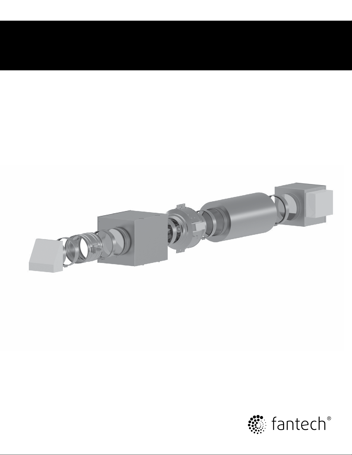
Installation Manual
Makeup Air System & Controller
Item #: 497831
Rev Date: 2015-07-09
United States
10048 Industrial Blvd., Lenexa, KS, 66215
Tel.: 800.747.1762 • Fax: 800.487.9915
Canada
50 Kanalflakt Way, Bouctouche, NB, E4S 3M5
Tel.: 800.565.3548 • Fax: 877.747.8116
Page 2

2
Note Warning /
Information Technical
Important
note
Warnings
TO REDUCE THE RISK OF FIRE, ELECTRIC SHOCK, OR INJURY TO PERSONS,
OBSERVE THE FOLLOWING:
1. Installation work and electrical wiring must be done by a qualified
person(s) in accordance with national electric codes, local electric
codes, ordinances and regulations, including fire-rated construction
codes and standards.
2. This system is not designed to provide combustion air for fuelburning appliances.
3. Do not connect the system directly to a combustion appliance of any
type.
4. Before servicing or cleaning any system component, switch power off
at service panel and lock the service disconnecting means to prevent
power from being switched on accidentally. When the service
disconnecting means cannot be locked, securely fasten a prominent
warning device, such as a tag, to the service panel.
5. When performing installation, servicing or cleaning of the system, it
is recommended to wear safety glasses and gloves.
6. Locate the outside air inlet hood above any anticipated snow drift
level and away from any architectural and landscape features to
ensure that the intake area for the outside air duct is not blocked and
provides a clear pathway for outside air to enter the system.
7. When cutting or drilling into wall or ceiling, do not damage electrical
wiring or other hidden utilities.
8. When notching or drilling into framing including floor supports, rim
joists, and wall studs, comply with code and manufacturer limitations
on allowable modifications to these structural members.
9. This system can only be used for its intended design. Any internal
wiring changes, modifications or bypass of any controls, or
installation practices not according to the details of the instruction
manual will void the product warranty. Follow all installation, wiring
and setup instructions indicated in the manufacturer’s manual.
Practical tip
information
Caution
1. Do not locate outside air inlet near hazardous materials or
explosives.
2. System shall not be installed to introduce air from crawlspaces,
garages, attics, adjacent dwelling units, or other locations within the
building shell. System shall be installed to introduce air directly from
outdoors.
3. Do not install the makeup air system and supply ductwork directly
above or closer than a distance of two feet to any furnace or its
supply plenum, boiler, or other heat producing appliance.
4. Any ductwork used in conjunction with the system must be installed
in compliance with all local and national codes that are applicable.
5. Do not operate the system until all system filters, including the
central duct system filter, have been installed per the system design.
6. Please read the specification label on each system component for
further information and requirements.
7. Each system component, including filters, should be inspected and
maintained on a regular basis.
8. This system is intended for installation in a dry location protected
from moisture.
9. This system must be installed in an accessible location which allows
for system inspection and maintenance.
10. This system will automatically provide outdoor air into a building.
Coordinate with the HVAC designer/contractor the effects that the
supply of outdoor air will have on the building’s comfort and the
central HVAC system. Consideration should be given to the
system’s frequency and duration of use, as well as the outdoor
airflow quantity and location as to where the outside air is delivered
into the building interior.
11. Use this system only in the manner intended by the manufacturer. If
you have questions, contact the manufacturer at the address or
telephone number provided in this document.
fantech
12. When federal, provincial or state legislation comprises more
restrictive installation and/or certification requirements, the
aforementioned requirements prevail over those of this document and
the installer agrees to conform to these at his own expense.
13. Do not supply outdoor air to a space or duct system where water
pipes or water coils might be susceptible to freezing due to the
supply of outdoor air.
Page 3
Application
3
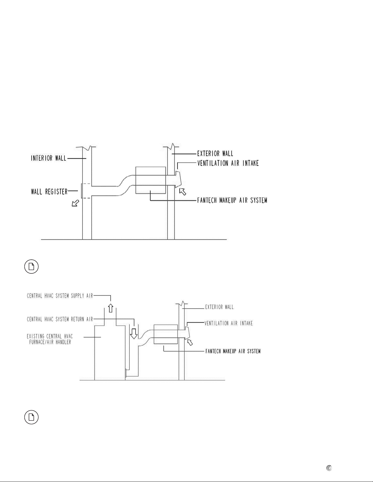
The Fantech Exhaust Makeup Air System is a low voltage controlled assembly
of components which provides the automatic supply of outdoor air into
a building. Typical system installation is shown in Figure 1. When controlled
by the current sensing Fantech Makeup Air Controller “FMAC”, the system is
suitable as compensation for single speed, multi-speed, and variable speed
exhaust fans.
The FMAC initiates the makeup air system upon sensing the exhaust fan motor
current, and controls the supply of outside air into the building in proportion to
that being exhausted.
This system may be used to replace air being removed by a kitchen hood
exhaust fan, bath exhaust, dryer booster (DEDPV) fan, or other continuously or
intermittently operating powered exhaust system. Mechanical replacement
of exhaust air allows an exhaust system to function more effectively, helps to
maintain pressure equilibrium between the building interior and the exterior,
and allows for management (quantity, cleaning, tempering and location) of the
introduction of outside air to the building’s interior space. An electric heater
(optional) may be included as a system component. The heater is not intended
to provide heating to the interior space, but rather to temper the supply of cold
outdoor air before it is delivered to the building.
Figure 1. Stand Alone Exhaust Makeup Air System
If the exhaust makeup air system is not selected to ensure that the delivered air temperature will not
cause condensation then the ductwork must be insulated.
Figure 2. Exhaust Makeup Air System Integrated with Central HVAC System (Not recommended)
Introducing outdoor makeup air via the central HVAC system is not recommended. If the installer chooses
to employ such a makeup air supply strategy, it will be the installer's responsibility to ensure the makeup air
system's compatibility with the HVAC system. Typical outdoor air conditions, during both winter and summer,
can have adverse effects on central HVAC equipment, potentially voiding warranties, contributing to premature
equipment failure, and resulting in condensation in equipment and duct work, among other problems. Such
adverse effects can result, even when the percentage of outdoor air to the central HVAC system's air ow is
small. Fantech does not endorse the use of the central HVAC system for makeup air supply.
fantech
Page 4
4
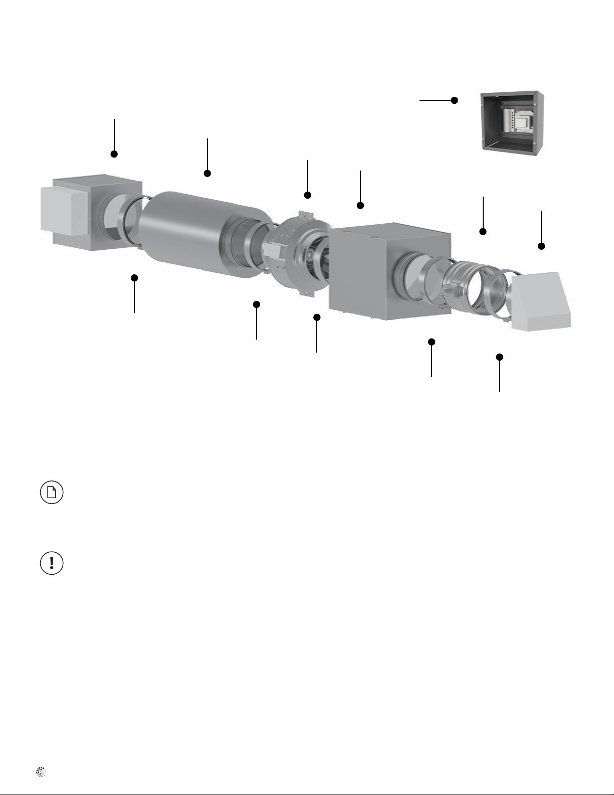
Exhaust Makeup Air System Components
7
2
Figure 3. Makeup Air System for Exhaust Fan
1 Wall Intake Hood, FML
2 Fast Clamp, FC
6
5
2
2
5 Makeup Air Fan, FG EC or FKD EC
6 Silencer, LD
8
4
3
1
2
2
3 Shut-off Damper, ADC
4 Filter cassette, FGR HV
*The FMAC Controller includes a transducer, system control board, 24V transformer, NEMA enclosure,
enclosure back plate for mounting transformer and controller, 4"x4" electrical box for supporting the
transformer.
7 Duct Heater, EM-WX (optional)
8 Controller, FMAC*
Items Which Must Be Furnished By Others:
a. Insulation
b. Wiring
c. Electrical Wiring Boxes
d. Equipment Supports/Hangers
e. Duct work
f. Electrical Disconnect Means
g. Miscellaneous Hardware and Any Other Items not described in this document
fantech
Page 5
Dimensions
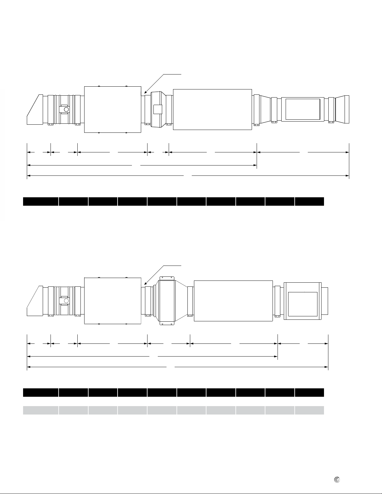
MUAS 650
5
Ø
J
A
B
C
D
E
F
G
Model A B C D E F H (optional) G J
MUAS 650 10 1/
2
11 7/
8
30 1/
2
9 5/
32
38 1/
2
100 1/
40 21/
2
141 5/
32
32
MUAS 1600 and MUAS 2000
Ø
J
H
12
A
B
C
D
E
F
G
Model A B C D E F H (optional) G J
MUAS 1600 10 1/
MUAS 2000 10 3/
2
4
11 7/
13 7/
8
8
30 1/
30 1/
2
2
18 7/
20 3/
8
8
38 1/
38 1/
2
2
110 1/
114 21 135 14
21 131 1/
5
5
H
12
fantech
Page 6
6
Makeup Air System Installation
Read all instructions before starting installation.
Low voltage wiring should be routed the shortest distance possible to
avoid unnecessary voltage drop.
The current transducer wire shall be a minimum 20 AWG twisted pair.
The current transducer and all control wires shall be kept away from high
voltage wiring to avoid signal interference.
Recommended ambient operating temperature range for the makeup air
system is -20oF (28.8oC) to 140oF (60oC). We recommend that the
installer insulate the entire length of the makeup air system and all duct
work connected to the system to prevent condensation from forming.
The installer is responsible to ensure that air entering gas/oil heat exchangers is 55oF (12.8oC) or greater and that air contacting water pipes
or water coils will not cause freezing
The 240V electric heater component (optional) must be installed on a
properly sized, dedicated electrical circuit. The supply fan and FMAC
transformer may be powered via a shared electrical circuit.
Installation Steps:
Each system component must be individually secured to the building
structure.
DO NOT ENERGIZE THE POWER TO ANY SYSTEM COMPONENT UNTIL THE
ENTIRE SYSTEM HAS BEEN INSTALLED AND IS READY FOR SETUP AND
STARTUP.
1. Install intake hood component per its instructions. Take care to locate
the intake appropriately on an exterior wall. Mind the warning and
caution statements in this document.
2. Install the motorized damper component per its instructions, and
connect it to the intake hood with a fast clamp. The damper is
furnished with a 24V AC motor, the damper control method is power
open and spring closed.
3. Install the lter module component per its instructions. Connect the
lter module to the motorized damper with a fast clamp. Make sure
the lter is accessible for cleaning and replacement.
4. Install the supply fan component per its instructions. Connect the
supply fan to the lter module with a fast clamp and a duct transition
(if necessary). The supply fan should be installed and mechanically
supported to reduce the transmission of fan/motor vibration to the
building structure.
5. Install the duct silencer component connecting to the supply fan with a
fast clamp.
6. Install the optional electric heater component (if included) per its
instructions. Connect the electric heater to the last component with
a fast clamp and a duct transition (if necessary). Connect the duct
heater to the supply duct work and install the heater’s temperature
sensor in the main warm air stream approximately 20" (500 mm) to
24" (610) downstream of the heating element. Drill a 1/2” (12.7mm)
hole in the duct, insert probe and screw in place.
7. Heater Control board is inside heater. Open cover to access it and set
the desired temperature for the heater using a small screwdriver. On
the circuit board marked “0 through 7”. This unit is equipped with a
default chip which has a broad range temperature span with settings
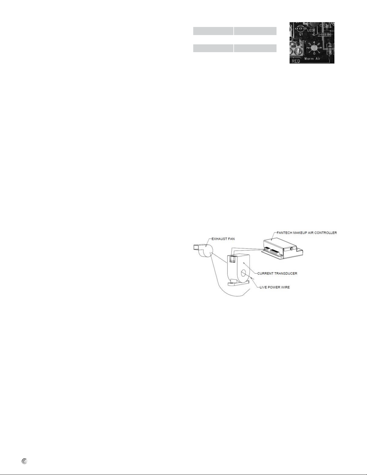
at 12° steps.
0 = 40°F (4.4°C) 4 = 88°F (26.7°C)
1 = 52°F (11.1°C) 5 = 100°F (37.8°C)
2 = 64°F (15.6°C) 6 = 112°F (44.4°C)
3 = 76°F (24.4°C) 7 = 124°F (51.1°C)
Figure 5. Heater Control Board
8. Install additional supply ductwork (if necessary). See Figure 1 and 2 for
possible supply duct arrangement. Other suitable supply duct systems
exist. It is recommended that the supply makeup air not be provided
directly to an occupied living space where thermal discomfort and
objectionable noise could result. Be mindful of the effect that the newly
installed quantity of outdoor air will have on the central HVAC system.
Coordinate efforts with the HVAC contractor to ensure compatibility.
9. Insulate all makeup air system components located where
condensation could form on cold surfaces, including all duct work
connected to the system.
10. Install the FMAC's 24V transformer onto the included 4"x4" electrical
box. Install the FMAC's controller and transformer w/ 4x4 box
onto the included back plate. Install the back plate into the included
NEMA enclosure. Secure the NEMA enclosure to the building
structure in a convenient, moisture-free, interior location near the
makeup air system.
11. Install the FMAC’s current transducer onto the power leg of the
wiring for the compensated exhaust fan (by others). The current
transducer must be installed close to the exhaust fan if not a
dedicated circuit. Install low voltage wire between the current
transducer and the FMAC’s makeup air controller. Reference the
wiring diagram in Figure 8 for wiring termination locations.
Figure 6. Current Transducer Wiring & Installation
12. Install low voltage wire between the transformer and FMAC’s makeup
air controller. Reference the wiring diagram in Figure 8 for wiring
termination locations. Provide 120/1/60 electrical power to the
transformer.
13. Provide 240/1/60 electrical power to the heater (optional, if included)
on a dedicated circuit. Reference the wiring diagram in Figure 8 for
wiring termination locations. The 10 Kw heater uses 42 amps and
the 20 Kw heater uses 80 amps.
14. Provide 120/1/60 electrical power to the supply fan. Install wiring
per all applicable codes. Refer to the wiring diagram in Figure 8 for
wiring termination locations.
15. Remove the 3-pronged potentiometer from the wiring terminal block
of the makeup air fan. The 3-pronged potentiometer will not be used
for the makeup air system. Install low voltage wiring between the
FMAC's makeup air controller and the makeup air fan. Refer to the
wiring diagram in Figure 8 for wiring termination locations.
16. Install low voltage wiring between the FMAC's makeup air controller
and the ADC shut-off damper. Refer to the wiring diagram in Figure
8 for wiring termination locations.
fantech
Page 7
Makeup Air Controller and System Startup:
7
Prior to beginning the setup and startup procedure, verify that the
makeup air system is completely installed and wired, and verify that the
compensated exhaust system is completely installed and wired.
a. Install a clean panel lter into the makeup air system’s lter cassette.
b. Energize the power circuits to;
• Makeup air fan.
• Transformer. A power indicator and heart pulse LED will illuminate
when the FMAC is energized and ready for programming.
• Electric heater (if included).
• The compensated exhaust system.
c. Operate the compensated exhaust fan on high speed.
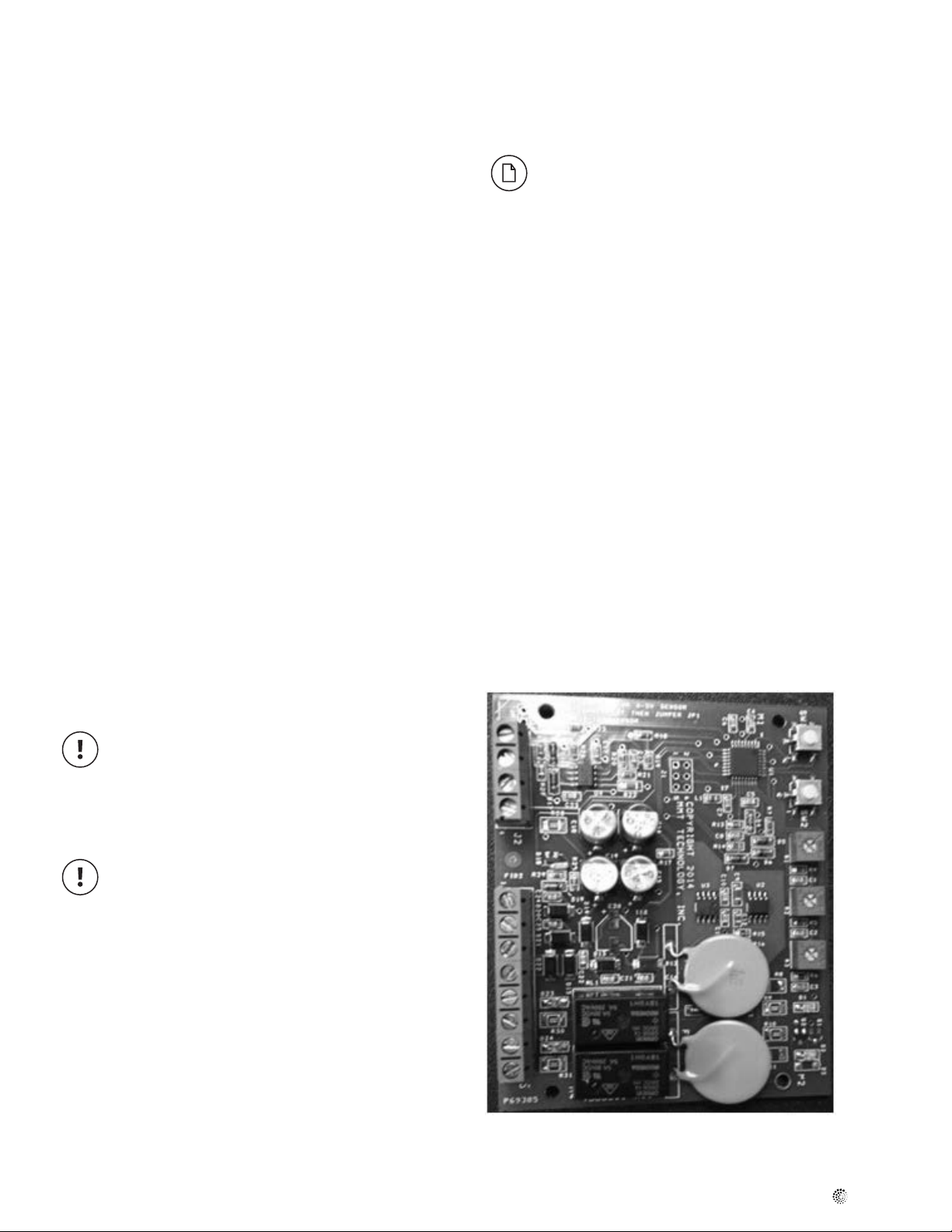
d. Press “HI” Button on makeup air controller.
e. Operate compensated exhaust fan on low speed.
f. Press “LO” Button on makeup air controller.
g. Operate the compensated exhaust fan at high speed and adjust the
makeup air fan controller “HT” trim pot to produce the desired CFM
from the makeup air fan. If the desired max CFM is not known; just set
the pot to max at this point. You will have an opportunity to ne tune
later.
h. Operate the compensated exhaust fan at low speed and adjust the
makeup air fan controller “LT” trim pot to produce the desired CFM
from the makeup air fan. If the desired min CFM is not known; just set
the pot to min at this point. You will have an opportunity to ne tune
later.
The FMAC is now ready for tuning.
Once the estimated required CFM of makeup air has been set it is time
to verify the house is correctly balanced.
If a slightly positive or negative (recommended no more than
5 Pa [0.02" w.g.] indoor pressure is desired, such a scheme can
be employed by this method, balancing to the desired pressure
scheme.
After adjusting the high and low speed trim the rst time, repeat the procedure as necessary until the system automatically operates sufciently
according to the desired pressure scheme at low, high and all intermediate speeds.
2. If a pressure differential gauge is not available, slightly open a window
approximately 1/2" (12mm) in the center of a building wall and check if
the airow is moving in or out. This can be done by feel , or by using a
light piece of tissue or paper, or one could use an anemometer. If the
ow is going out , the house is under positive pressure and the exhaust
makeup air fan needs to be slowed down using the high speed trim pot
"HT". If the airow is coming in, the house is under negative pressure
and the exhaust makeup air fan speed needs to be increased using the
high speed trim pot "HT". Repeat this procedure with the compensated
exhaust fan on low speed and using the "LT" trim pot. With both the
"HT" and "LT" trim pots adjusted the air pressure in the house will be
stabilized throughout the compensated exhaust fan range.
The FMAC is now ready for service. At this point the makeup air system
is controlled by the FMAC. As the exhaust fan speed is changed depend-
ing on use, the makeup air fan will sense the current draw and supply the
proper amount of ltered fresh air into the house to compensate for the
exhaust air. If the optional electric heater is installed, the supply air will
be warmed to the desired set point..
During setup and balancing it is necessary that all of the building's exterior openings are tightly closed. Openings include
windows, doors, ue dampers, etc. Also, de-energize any
systems that employ exhaust or supply air communication with
the outdoors. Such systems include clothes dryers, heating appliances, HRV's or ERV's, and bathroom ventilation fans.
Energize both the makeup air system and the compensated
exhaust system. Operate the compensated exhaust system's fan
on high speed.
Adjust the exhaust makeup air system airow by following one of the following two methods:
1. Using a pressure differential gauge (either digital or analog, as used
for blower door testing), measure the house pressure with respect to
the outdoors across a door or window. If the house pressure is positive with respect to the outdoors, slow down the exhaust makeup air
fan using the high speed trim pot "HT". If the house pressure is negative with respect to the outdoors, speed up the exhaust makeup air
fan using the high speed trim pot "HT". Repeat this procedure with the
compensated exhaust fan on low speed and using the "LT" trim pot.
HI
LO
HT
LT
Figure 7. FMAC Circuit Board
fantech
Page 8
8
Controller Operation and System Wiring
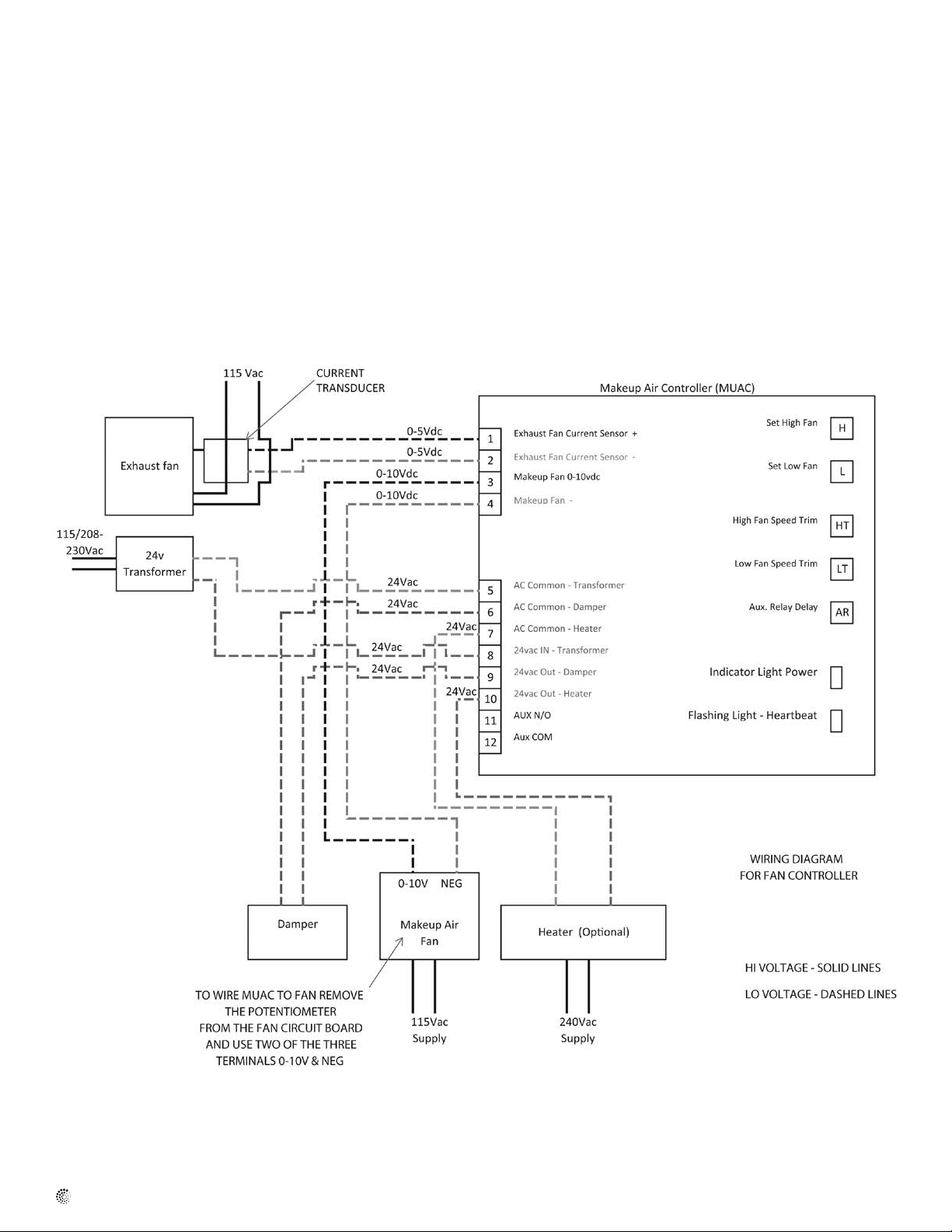
When the FMAC's controller receives a signal from the current transducer that the compensated exhaust fan is operating, the FMAC controller's
outputs will be activated.
The controller will provide a 24VAC signal to power the motorized
damper to the open position.
The controller will provide a 0-10VDC signal to the makeup air supply fan
to operate the fan at a speed proportional to the compensated exhaust
fan's speed.
The controller will provide a 24VAC signal to enable the optional duct
heater (if included). Note that the duct heater includes its own operation-
al sequence, and will only operate if rst enabled by the FMAC controller,
and then only if the supply air temperature requires that heat be added.
Figure 8. System Wiring Diagram
fantech
Page 9

Notes
9
All wiring is by others. Wiring terminations for each component are
contained in their respective installation instructions.
Placement of components is up to the discretion of the installing contractor.
fantech
Page 10

10
Warranty
Five (5) Year Warranty
This warranty supersedes all prior warranties
DURING ENTIRE WARRANTY PERIOD:
Fantech will repair or replace any part which has a factory defect in
workmanship or material. Product may need to be returned to the
Fantech factory, together with a copy of the bill of sale and identified
with RMA number.
FOR FACTORY RETURN YOU MUST:
• Have a Return Materials Authorization (RMA) number. This may be
obtained by calling Fantech either in the USA at 1.800.747.1762 or
in CANADA at 1.800.565.3548. Please have bill of sale available.
• The RMA number must be clearly written on the outside of the carton, or the carton will be refused.
• All parts and/or product will be repaired/replaced and shipped back to
buyer; no credit will be issued.
OR
The Distributor may place an order for the warranty part and/or product
and is invoiced. The Distributor will receive a credit equal to the invoice
only after product is returned prepaid and verified to be defective.
FANTECH WARRANTY TERMS DO NOT PROVIDE FOR REPLACEMENT
WITHOUT CHARGE PRIOR TO INSPECTION FOR A DEFECT.
REPLACEMENTS ISSUED IN ADVANCE OF DEFECT INSPECTION ARE
INVOICED, AND CREDIT IS PENDING INSPECTION OF RETURNED
MATERIAL. DEFECTIVE MATERIAL RETURNED BY END USERS SHOULD
NOT BE REPLACED BY THE DISTRIBUTOR WITHOUT CHARGE TO THE
END USER, AS CREDIT TO DISTRIBUTOR’S ACCOUNT WILL BE
PENDING INSPECTION AND VERIFICATION OF ACTUAL DEFECT BY
FANTECH.
THE FOLLOWING WARRANTIES DO NOT APPLY:
• Damages from shipping, either concealed or visible. Claim must be
filed with freight company.
• Damages resulting from improper wiring or installation.
• Damages or failure caused by acts of God, or resulting from improper
consumer procedures, such as:
1. Improper maintenance
2. Misuse, abuse, abnormal use, or accident, and
3. Incorrect electrical voltage or current.
• Removal or any alteration made on the Fantech label control number
or date of manufacture.
• Any other warranty, expressed, implied or written, and to any consequential or incidental damages, loss or property, revenues, or profit,
or costs of removal, installation or reinstallation, for any breach of
warranty.
WARRANTY VALIDATION
• The user must keep a copy of the bill of sale to verify purchase date.
• These warranties give you specific legal rights, and are subject to an
applicable consumer protection legislation. You may have additional
rights which vary from state to state.
Limitation of Warranty and Liability
This warranty does not apply to any Fantech product or part which has
failed as a result of faulty installation or abuse, incorrect electrical connections or alterations made by others, or use under abnormal operating
conditions or misapplication of the product or parts. We will not approve
for payment any repair not made by us or our authorized agent without
prior written consent. The foregoing shall constitute our sole and exclusive warranty and our sole exclusive liability, and is in lieu of any other
warranties, whether written, oral, implied or statutory. There are no
warranties which extend beyond the description on the page hereof. In no
event, whether as a result of breach of contract, or warranty or alleged
Warning
Fantech products are designed and manufactured to provide reliable performance, but they are not guaranteed to be 100% free from defects.
Even reliable products will experience occasional failures and this possibility should be recognized by the user. If these products are used in a
negligence, defect incorrect advice or other causes, shall Fantech be liable for special or consequential damages, including, but not limited to,
loss of profits or revenue, loss of use of equipment or any other associated equipment, cost of capital, cost of substitute equipment, facilities
or services, downtime costs, or claims of customers of purchase for
such damages. Fantech neither assumes or authorizes any person to
assume for it any other liability in connection with the sale of product(s)
or part(s). Some jurisdictions do not allow the exclusion or limitation of
incidental or consequential damages so the above limitations and exclusions may not apply to you.
life support ventilation system where failure could result in loss or injury,
the user should provide adequate backup ventilation, supplementary natural ventilation, failure alarm system, or acknowledge willingness to
accept the risk of such loss or injury.
fantech
Page 11

11
fantech
Page 12

Fantech reserves the right to make technical changes.
For updated documentation please refer to www.fantech.net
Fantech®
 Loading...