

Page 1
Item #: 301032
Rev Date: 2015-05-12
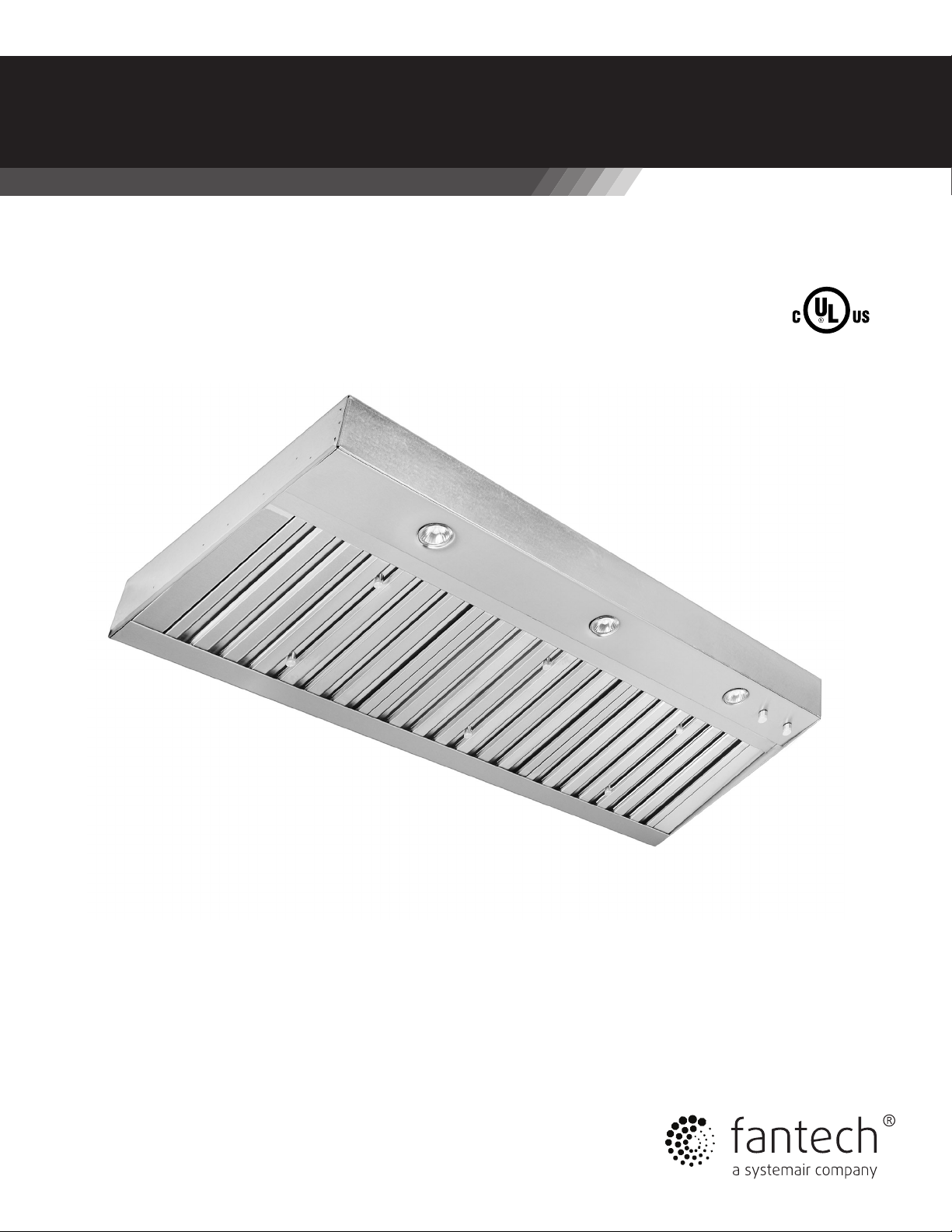
HL Series
Range Hood Liners
Item #: 301032
Rev Date: 2016-05-25
Installation and Operation Manual
Techical / Customer Support:
United States Tel.: 800.747.1762 Canada Tel.: 800.565.3548
Page 2
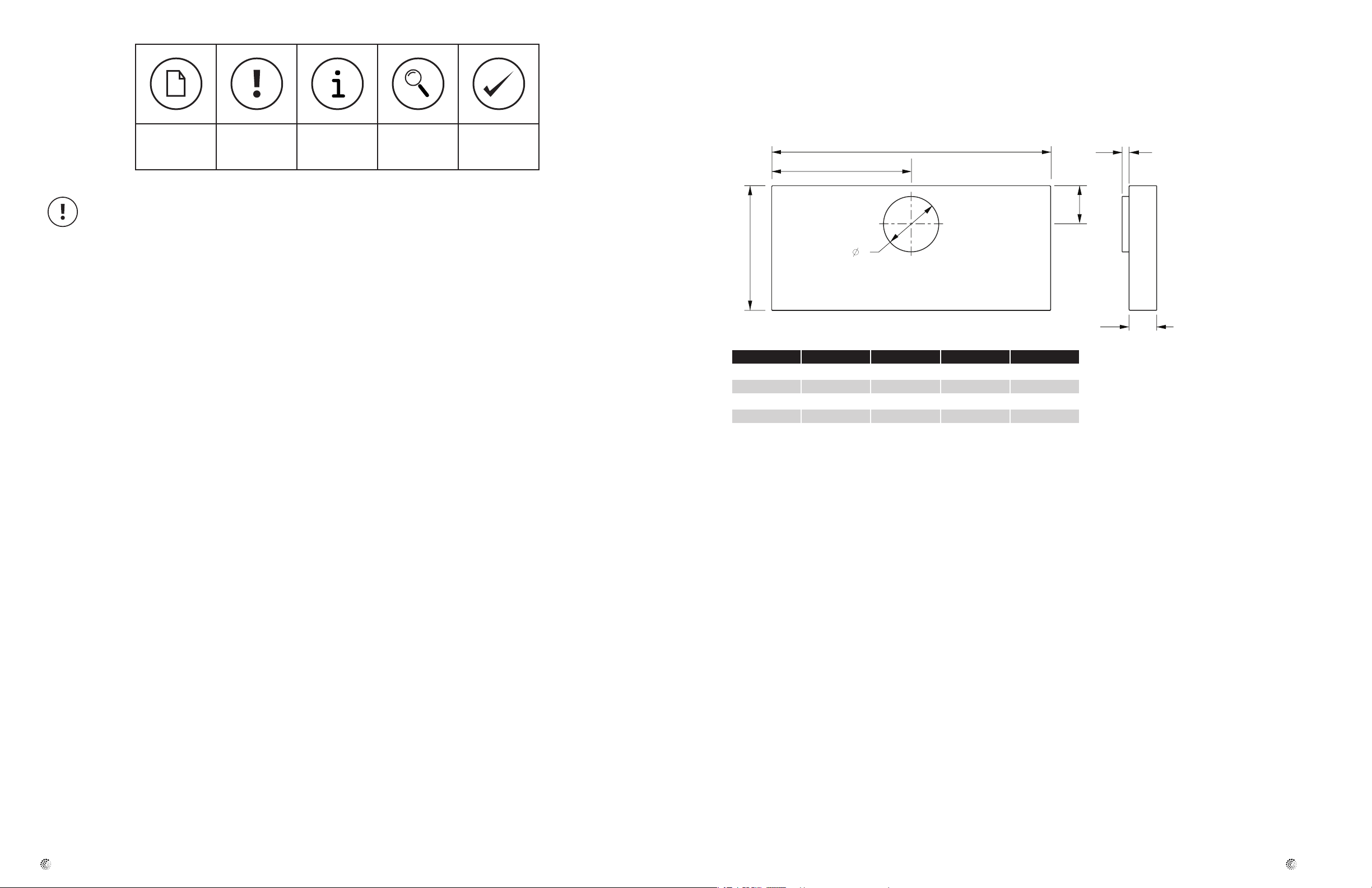
A
B
C
1
18
D
4
Dimensions
HL Series
32
Note Warning /
Information Technical
Important
note
READ THESE INSTRUCTIONS COMPLETELY BEFORE INSTALLING FAN AND
SAVE THESE INSTRUCTIONS FOR FUTURE REFERENCE.
• Before beginning installation, please thoroughly read and become
familiar with these instructions.
• Installation and service must be completed by a qualified installer.
• Failure to properly install this product may void the warranty.
TO REDUCE THE RISK OF FIRE, ELECTRIC SHOCK, OR INJURY TO PERSONS,
OBSERVE THE FOLLOWING:
• Use this unit only in the manner intended by the manufacturer. If you
have any questions, contact the manufacturer.
• Before servicing or cleaning unit, switch power off at service panel and
lock the service disconnecting means to prevent power from being
switched on accidentally. When the service disconnecting means
cannot be locked, securely fasten a prominent warning device, such as
a tag to the service panel.
• Installation work and electrical wiring must be done by qualified
person(s) in accordance with all applicable codes and standards,
including fire-rated construction.
• Sufficient air is needed for proper combustion and exhausting of gases
through the flue (chimney) or burning equipment to prevent back
drafting. Follow the heating equipment manufacturer’s guideline and
safety standards such as those published by the National Fire
Protection Association (NFPA) and the American Society for Heating,
Refrigeration and Air Conditioning Engineers (ASHRAE) and the local
code authorities.
Practical tip
information
CAUTION: For general ventilating use only. Do not use to exhaust
hazardous or explosive materials and vapors.
TO REDUCE THE RISK OF A RANGE TOP GREASE FIRE:
• Never leave surface units unattended at high settings. Boil-overs may
cause smoking and greasy spillovers that may ignite. Heat oils slowly
on low or medium settings.
• Always turn hood ON when cooking at high heat or when cooking
flaming foods.
• Clean ventilating fans frequently. Grease should not be allowed to
accumulate on fan or filter.
• Use proper pan size. Always use cookware appropriate for the size of
the surface element.
TO REDUCE THE RISK OF INJURY TO PERSONS IN THE EVENT OF A RANGE
TOP GREASE FIRE, OBSERVE THE FOLLOWING:
• SMOTHER FLAMES with a close-fitting lid, cookie sheet or metal tray,
then turn off the burner. BE CAREFUL TO PREVENT BURNS. If the
flames do not go immediately, EVACUATE AND CALL THE FIRE
DEPARTMENT.
• NEVER PICK UP A FLAMING PAN You may be burned.
• DO NOT USE WATER, including wet dishcloths or towels – a violent
steam explosion will result.
• Use an extinguisher ONLY if:
Model A B C D
HL 30 28 3/8 14 3/16 5 1/2 8
HL 36 34 3/8 17 3/16 5 1/2 8
HL 42 40 3/8 20 3/16 6 1/2 10
HL 48 46 3/8 23 3/16 6 1/2 10
Dimensional information is in inches
All dimensional tolerances are 0” to 1/16” unless otherwise stated.
• Building codes require Makeup air for any hood system exhausting
over 400 cfm.
• When cutting or drilling into wall or ceiling, do not damage electrical
wiring and other hidden utilities.
• Duct fans must always be vented to the outdoors.
fantech
• You know you have a Class ABC extinguisher, and you already know
how to operate it.
• The fire is small and contained in the area where it started.
• The fire department is being called.
• You can fight the fire with your back to an exit.
fantech
Page 3
54
Planning the Installation
1. To reduce the risk of re and to properly exhaust air, the liner must
be exhausted to the outside. Never exhaust into a wall, an attic or a
concealed area in the building. This can create a potential hazard.
2. Consult a licensed ventilation contractor or qualied technician for
proper installation of exhaust ducting.
3. Locate the cooking area for minimum cross drafts – away from doors
and windows, when possible.
4. Ducts must be of adequate size and duct runs should be as short as
possible. Where turns are necessary, keep turning radius as large and
as smooth as possible.
5. The ducting must be air tight. Use a minimum of 2 sheet metal screws
at every duct joint. Then, seal the duct joints with high quality duct
tape.
6. Only use ductwork constructed of materials deemed acceptable by
state, municipal and local codes.
WARNINGS: Following Are Manufacturer’s Suggestions. Always Observe
Local Building Codes.
• Liners installed in custom canopies constructed of combustible
materials, should be installed with the combustible material structure
a minimum of 36” above the surface of the heating element.
• Liners installed in custom canopies constructed of non-combustible
materials, should be installed with the non-combustible material
structure a minimum of 30” above the surface of the heating element.
• Follow all instructions regarding minimum safe clearances and
installation location. Failure to do so may result in a safety hazard or
re.
• To reduce the risk of re use only metal ductwork.
•Thehoodlinerisdesignedtoinstallinsideacustomhoodenclosure
and operates with a remote mount blower (purchased separately). See
dimensional drawings (page 3) for hood dimensions. See chart (page 7)
for Fantech exhaust fans recommended for use with these units.
•Aqualiedpersonmustcompletetheinstallationofthisappliance.
•Plantheinstallationsothatallminimumclearancearemetor
exceeded.
•IMPORTANT:Youmustprovidesupportframingandbackinginthe
areas in which you are securing the liner to in your custom canopy.
Failure to do so could damage the liner and void the warranty.
• The HL30 and HL36 is designed for use with a 8” diameter duct. The
HL 42 and HL 48 are designed for use with a 10” diameter duct. Use
only rigid metal duct.
• For a truly quiet kitchen ventilation system add a Fantech “duct
silencer” (LD Series) to the installation. The simple addition of an inline
duct silencer between the hood liner and the remote fan can typically
reduce the “perceived” sound level of the system by more than 50%.
For more information visit www.fantech.net.
• A quality cap with built in backdraft damper or an inline damper is
recommended to minimize cold air return through the duct when the
product is not in use.
• Always install ventilation products with an approved wall or roof cap.
• Duct performance is improved by using round, smooth metal duct work
instead of rectangular.
• If multiple elbows must be used, ensure that there is a minimum of 24”
of straight duct between any two elbows.
• Avoid ”S:” or back to back congurations caused by adjacent elbows.
Electrical Connections
1. Ensure that the power supply is disconnected before proceeding.
2. Verify that the power supply matches the ratings found on the
appliance data label before proceeding.
3. The complete appliance must be properly grounded at all times when
electrical power is applied.
4. Do not ground the appliance with the neutral (white) house supply wire.
A separate ground wire must be utilized.
5. Failure to complete electrical connections properly may result in
damaged or non-functional systems. Follow instructions carefully to
ensure proper installation.
• It is the owner’s responsibility to ensure that a qualied electrician
performs the electrical connection of this appliance. The electrical
installation, including minimum supply wire size, must comply with the
National Electric Code ANSI/NFPA 70-1990 (or latest revision) and
local codes and ordinances.
• A copy of this standard may be obtained from: National Fire Protection
• Association,1 Batterymarch Park Quincy, Massachusetts 02269-9101
Instructions
1. A 15 to 20 amp electrical service is recommended for proper electrical supply. Before determining, calculate amp ratings based on the
product label found on the liner and the ventilator. (Always observe
local building codes).
2. Always use a dedicated circuit.
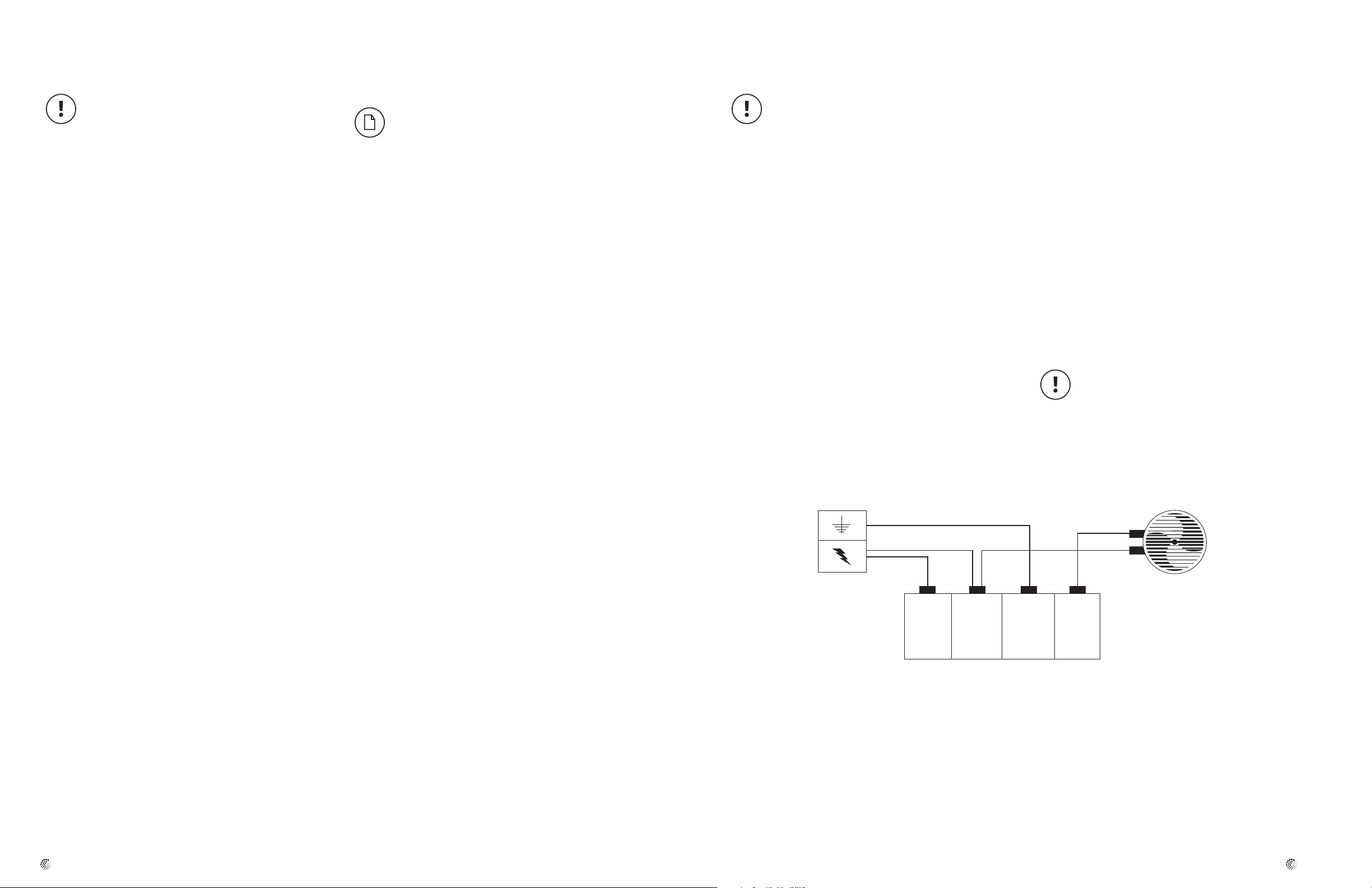
Green
White
120V Black
Electrical
Panel
3. Line load is calculated by adding the amperage of the halogen lights to
the rated amperage of the ventilator (either in-line or roof top). If the
ventilator is rated in watts rather than amps, divide the watts by 120
and this will give you the amperage rating.
4. The Fantech liner is supplied with a 5.0 amp variable speed fan control. Make sure the rated amperage on the ventilator does not exceed
5.0 amps. For larger ventilators rated above 5.0 amps, contact
Fantech Customer Service for recommendations.
5. The Fantech liner has been designed to accommodate several different motor speed controls, (for example ThermadorTM model CTR3-Q)
Always consult the manufacturer’s installation instructions when substituting control switches.
6. Wire connections (see internal wiring schematic):
•Black–120VACfromelectricalpanel(black)
•White-Neutralfromelectricalpanel(white)
•Green–Groundfromelectricalpanel(green)
•Red-120VACvariablecontrolto120VACofventilator
The neutral wire (usually white) for the ventilator must connect to the
same neutral wire that comes from the electrical panel to the liner. It is
recommended to run a white neutral wire from the liner’s white neutral
wire along the same path as the red wire from the liner’s variable speed
control to the ventilator.
120V Red
VentilatorHouse
• Route ducting to terminate at the hood liner.
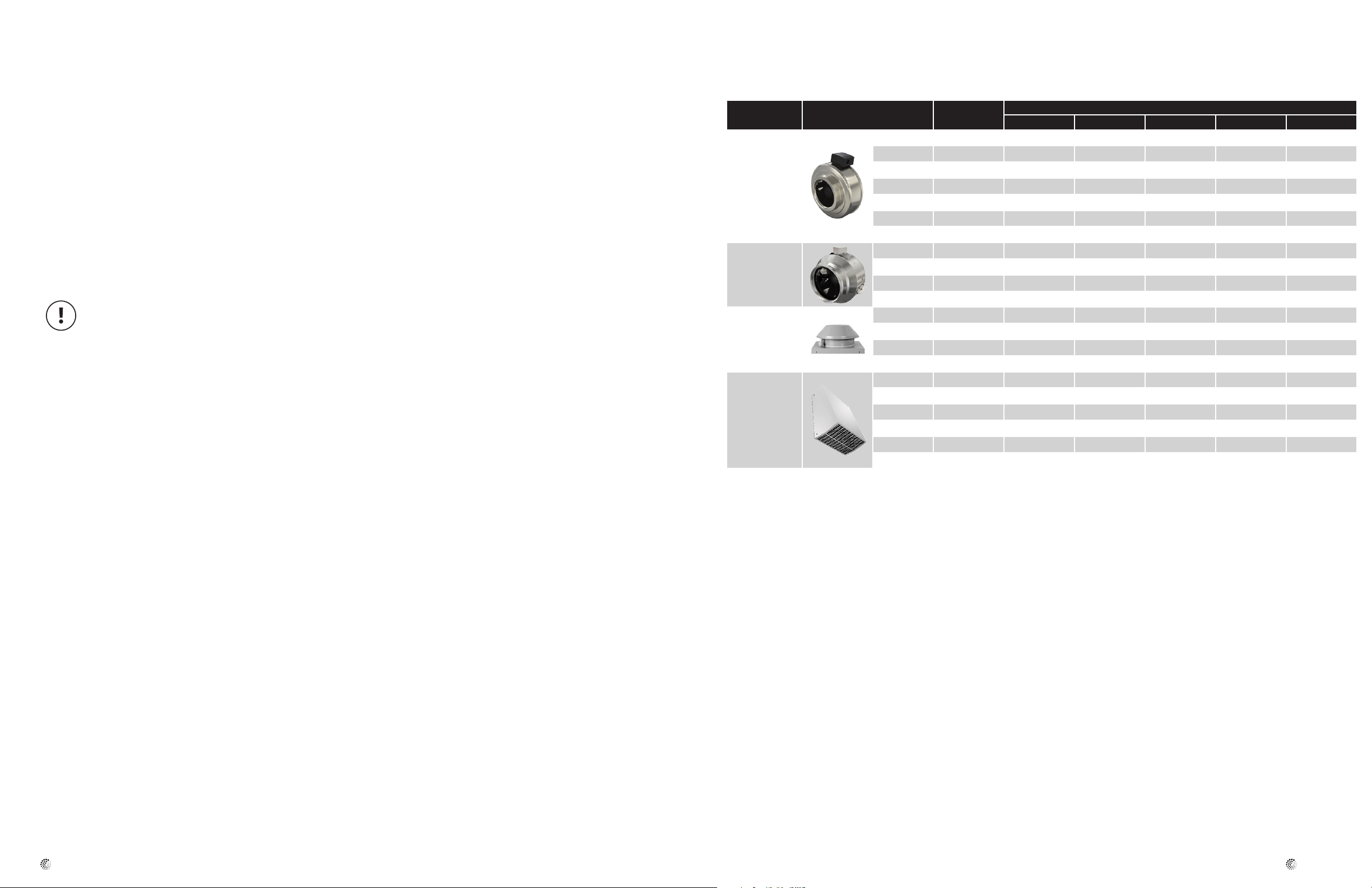
Choosing the right remote mount blower (see page 7)
Look on page 7 for a list of Fantech fans recommended for use with the HL Series Range Hood Liners. Some models remotely mount in the attic.
Other models are used when installation requires a roof mount or wall mount fan.
fantech
Black
White
Securing the Liner
Securing instructions
1. Because the professional series liner was designed for custom applications, no mounting holes have been pre-drilled. This allows you to
attach the liner in the areas of the canopy which have ample support
and backing.
2. You must secure the liner through both right and left sides, through
the back and through the top.
3. Remove the filters. Mark and drill screw holes through the liner as
required for custom canopy. Secure the liner by driving screws (pro-
Green
Red
vided by others) through the liner into the framing and backing.
Connection to the vent pipe
1. The hood liner has an integral vent connection start collar that is
welded in place at the factory. Attach the vent pipe to the start collar
with a minimum of 3 equidistantly spaced screws.
2. Cover the screw heads and exposed seams with metal-backed tape.
3. Vent pipe should be supported in place separately from the hood liner.
Do not use the hood liner to support the vent pipe’s weight.
fantech
Page 4
76
Use & Care
Operation controls
1. Always activate the ventilator whenever using cooking appliances.
2. Activate the ventilator a few minutes before starting to cook to establish an airflow pattern within the room.
3. Adjust the fan speed according to the amount of cooking exhaust.
4. Adjust the dimmable halogen lights as desired.
5. Eliminate air currents in the hood vicinity by shutting nearby windows
and doors, turning off ceiling fans and closing the adjacent heating and
air conditioning outlets.
6. Place your largest pans, skillets and stock pots on the rear burners
whenever possible.
DO NOT operate the vent system without the filters in place,
or with dirty, grease laden filters.
Energy saving tips
1. Do not operate the blower at a speed that is higher than necessary to
remove the cooking exhaust. Running at excessive speeds removes
more air from the inside of the house that must be replaced by outside air. This may be especially costly when your home’s heating or air
conditioning system is in operation. Turn off the unit once the smoke
and cooking odors have been eliminated.
2. Clean filters and grease laden surfaces often to improve efficiency.
3. Always use lids on cookware to retain heat and moisture.
4. Minimize the amount of liquid used to cook food.
5. Select cookware of proper size, material and construction for the
cooking task being performed.
Care & Cleaning
1. Proper cleaning is necessary to maintain performance and appearance, while also ensuring safe operation. The frequency of cleaning
should be adjusted according to the type and amount of cooking. Best
results will be achieved by cleaning soiled components as soon as possible.
2. Filters must be cleaned regularly.
Remove one filter at a time, grasp the filter handle and gently pull
toward you, then down and back. Filter should be installed with the
handle in the rear filter slot.
3. The filters may be cleaned by hand washing in hot water using a mild
detergent solution, or by placing them in the top rack of an automatic
dishwasher. Dry the filters completely before using again.
4. Stainless steel surfaces should be cleaned with a solution of mild
detergent and warm water. Rinse and dry with a soft lint-free cloth.
CAUTION: Do not use any type of pad that will scratch the liner
5. CAUTION: If a commercially available stainless steel cleaner is used. It
is important to read the labels for chlorine compounds. Chlorine is a
corrosive substance. If these compounds are present, rinse thoroughly
and dry with a soft lint-free cloth. Follow polish manufacturer’s instructions.
6. Always wipe stainless steel surfaces with the grain. Never wipe
across the grain.
7. After cleaning, reinstall the filters carefully.
Replacing light bulb
It is recommended that replacement bulbs with characteristics matching
those of the original bulbs are used. The original bulbs furnished with the
HL Series hood liners are:
Choosing the Right Remote Mount Blower
Fan location Fan model Air Flow Rate (cfm)
FG 6 303 8 275 275 - -
FG 6XL 483 8 381 381 381 -
FG 8 461 8 359 359 359 -
Remote Interior
Remote Interior
Remote Exterior
Roof or Wall
Remote Exterior Wall
* Hood liner model application air ow rates estimated for system with 20 feet of duct, two 90 deg. elbows, a backdraft damper, roof cap and hood lters.
** Duct size is recommended for the fan’s air ow rate. Size transitions may be necessary for duct connection to hood liner and fan. Other duct-mounted accessories, such as backdraft damp-
ers, silencers, and roof caps, are recommended to be same size as duct diameter..
FG 8XL 502 8 427 427 427 427
FG 10 513 10 - 494 494 494
FG 10XL 589 10 - 570 570 570
FG 12XL 940 12 - - - 806
FKD 8XL 836 8 - 440 440 440
FKD 10 910 10 - - 772 772
FKD 10XL 1266 10 - - 973 973
FKD 12XL 2016 12 - - - 1384
RE/REC 6 227 6 180 - - -
RE/REC 8XL 409 8 355 355 355
RE/REC 10XL 753 10 - - 715 715
RE/REC 10XLT 1008 10 - - - 883
RVF 6 242 6 172 172 - -
RVF 6XL 381 8 338 338 338 -
RVF 8XL 435 8 321 321 321 321
RVF 10 790 10 - - 646 646
RVF 10L 1060 10 - - - 842
RVF 10XL 1245 10 - - - 880
at 0.0” Ps
Duct Size** (in) HL 30 HL 36 HL 42 HL 48
Hood Liner Model Application Air Flow Rate* (cfm)
fantech
- 50 Watt, type MR16 halogen lamp with a GU10 base
fantech
Page 5

Five (5) Year Warranty
This warranty supersedes all prior warranties
DURING ENTIRE WARRANTY PERIOD:
Fantech will repair or replace any part which has a factory defect in
workmanship or material. Product may need to be returned to the
Fantech factory, together with a copy of the bill of sale and identified
with RMA number.
FOR FACTORY RETURN YOU MUST:
•HaveaReturnMaterialsAuthorization(RMA)number.Thismaybe
obtained by calling Fantech either in the USA at 1.800.747.1762 or
in CANADA at 1.800.565.3548. Please have bill of sale available.
•TheRMAnumbermustbeclearlywrittenontheoutsideofthecar-
ton, or the carton will be refused.
•Allpartsand/orproductwillberepaired/replacedandshippedbackto
buyer; no credit will be issued.
OR
The Distributor may place an order for the warranty part and/or product
and is invoiced. The Distributor will receive a credit equal to the invoice
only after product is returned prepaid and verified to be defective.
FANTECH WARRANTY TERMS DO NOT PROVIDE FOR REPLACEMENT
WITHOUT CHARGE PRIOR TO INSPECTION FOR A DEFECT.
REPLACEMENTS ISSUED IN ADVANCE OF DEFECT INSPECTION ARE
INVOICED, AND CREDIT IS PENDING INSPECTION OF RETURNED
MATERIAL. DEFECTIVE MATERIAL RETURNED BY END USERS SHOULD
NOT BE REPLACED BY THE DISTRIBUTOR WITHOUT CHARGE TO THE
END USER, AS CREDIT TO DISTRIBUTOR’S ACCOUNT WILL BE
PENDING INSPECTION AND VERIFICATION OF ACTUAL DEFECT BY
FANTECH.
THE FOLLOWING WARRANTIES DO NOT APPLY:
•Damagesfromshipping,eitherconcealedorvisible.Claimmustbe
filed with freight company.
•Damagesresultingfromimproperwiringorinstallation.
•DamagesorfailurecausedbyactsofGod,orresultingfromimproper
consumer procedures, such as:
1. Improper maintenance
2. Misuse, abuse, abnormal use, or accident, and
3. Incorrect electrical voltage or current.
•RemovaloranyalterationmadeontheFantechlabelcontrolnumber
or date of manufacture.
•Anyotherwarranty,expressed,impliedorwritten,andtoanyconse-
quential or incidental damages, loss or property, revenues, or profit,
or costs of removal, installation or reinstallation, for any breach of
warranty.
WARRANTY VALIDATION
•Theusermustkeepacopyofthebillofsaletoverifypurchasedate.
•Thesewarrantiesgiveyouspecificlegalrights,andaresubjecttoan
applicable consumer protection legislation. You may have additional
rights which vary from state to state.
Limitation of Warranty and Liability
This warranty does not apply to any Fantech product or part which has
failed as a result of faulty installation or abuse, incorrect electrical
connections or alterations made by others, or use under abnormal
operating conditions or misapplication of the product or parts. We will
not approve for payment any repair not made by us or our authorized
agent without prior written consent. The foregoing shall constitute our
sole and exclusive warranty and our sole exclusive liability, and is in lieu
of any other warranties, whether written, oral, implied or statutory.
There are no warranties which extend beyond the description on the
page hereof. In no event, whether as a result of breach of contract, or
Warning
Fantech products are designed and manufactured to provide reliable
performance, but they are not guaranteed to be 100% free from
defects. Even reliable products will experience occasional failures and
this possibility should be recognized by the user. If these products are
warranty or alleged negligence, defect incorrect advice or other causes,
shall Fantech be liable for special or consequential damages, including,
but not limited to, loss of profits or revenue, loss of use of equipment or
any other associated equipment, cost of capital, cost of substitute
equipment, facilities or services, downtime costs, or claims of
customers of purchase for such damages. Fantech neither assumes or
authorizes any person to assume for it any other liability in connection
with the sale of product(s) or part(s). Some jurisdictions do not allow the
exclusion or limitation of incidental or consequential damages so the
above limitations and exclusions may not apply to you.
used in a life support ventilation system where failure could result in loss
or injury, the user should provide adequate backup ventilation,
supplementary natural ventilation, failure alarm system, or acknowledge
willingness to accept the risk of such loss or injury.
 Loading...