

Fantasea EyeGrabber FP7000 Instruction Manual
EyeGrabber FP7000 Instruction Manual 20110523
Fantasea EyeGrabber FP7000
(Cat. No. 4057)
Instruction Manual
The EyeGrabber FP7000 allows for secure storage of Fantasea accessory lenses and filters when not installed on the
housing.
Compatible with the Following Lens Accessories:
BigEye Lens FP7000 (Cat. No. 5136)
EyeDaptor FP7000-F67 (Cat. No. 4702) - with any lens mounted on top of the adaptor
EyeDaptor S90/S95-F67 (Cat. No. 4710) - with any lens accessory mounted on top of the adaptor
RedEye Filter FP7000 (Cat. No. 5211)
PinkEye Filter FP7000 (Cat. No. 5212)
SharpEye Lens M67 (Cat. No. 5128) - only when mounted on top of the EyeDaptor FP7000-F67 (Cat. No.
4702)
Any of the lens accessories mentioned above can still be mounted on the EyeGrabber when color correction
inserts are installed inside
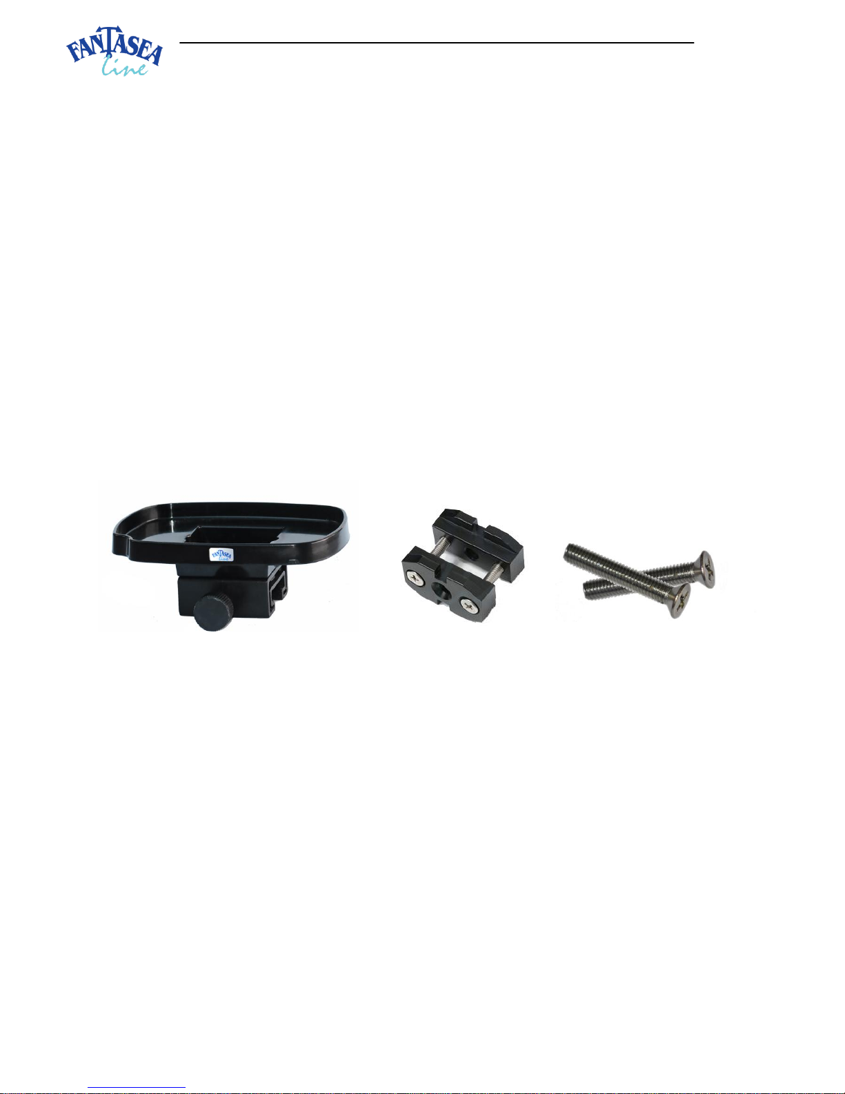
Included in the Kit:
Instructions for Use:
1. Assembling the EyeGrabber Lens Holder on a Flex or Ball & Joint Arm
a. Please use the utmost care and do not use excessive force when assembling and disassembling the different
accessories, in order to not cause any damage to the products.
b. It is advisable to mount the EyeGrabber on the arm prior to installing the arm on the housing tray or handle.
c. Remove the screws from the T2 Connector so that the two parts of the T2 Connector are disconnected. Please
note that there are two sets of screws included in the kit. The type of screws compatible with your arm
depends on the model of the arm. In general, longer screws are compatible with wider arms, such as Fantasea
Flex arms, while shorter screws are compatible with narrower arms, such as Ball & Joint arms. Choose the
proper set of screws for your system and leave the screws installed only inside the front part of the T2
Connector (image #1 on the following page). Keep the other set of screws in storage for future use, in case you
replace the arms used in your system.
T2 Connector
Set of 2 shorter screws
EyeGrabber FP7000

EyeGrabber FP7000 Instruction Manual 20110523
d. If assembling the EyeGrabber on a Flex arm, gently rotate the links of the
arm so that two sequential holes positioned on the upper half of the arm
are aligned in a way that enables inserting screws inside (image #2). If
assembling the EyeGrabber on a Ball & Joint arm, simply choose two slots
on the upper half of the arm which the EyeGrabber will be assembled
through.
e. Hold the front part of the T2 connector with the two screws installed inside in front of the arm, so that the
screws are aligned with the two holes or slots in the arm. Insert the screws through the holes or slots of the
arm (image #3). Any resistance encountered might be due to improper alignment of the holes on the Flex arm
or due to the resistance of the nylon support line found inside the Flex arm. In such a case, please repeat step
1c and make sure the support line doesn’t get in your way.
f. Hold the rear part of the T2 Connector on the other side of the arm, so the narrow side of it is facing the arm
and is aligned with the screws (the flared side with conical holes should be facing outward). Insert the screws
into this part of the connector as well and tighten them till both sides of the T2 Connector are stable on the
arm (image #4). If the screws are too short to reach the end of the rear connector, replace them with the set
of longer screws. If the screws are too long and stick out from the back of the connector, replace them with
the set of shorter screws.
Image #1
Image #2
Image #3
Image #4
 Loading...