

fann DNA 102410489 Instruction Manual
Data Network Adapter (DNATM) System
Instruction Manual
Manual No. D00981262, Revision A
Instrument No. 102410489

DNATM System Instruction Manual
Phone
1-281-871-4482
Fax
1-281-871-4358
Postal Address
Fann Instrument Company
Shipping Address
Fann Instrument Company
Online
www.fann.com
DNA™ System Instruction Manual
©2015 Fann Instrument Company
Houston, Texas, USA
All rights reserved. No part of this work covered by the copyright hereon may be reproduced or
copied in any form or by any means (graphic, electronic, or mechanical) without first receiving the
written permission of Fann Instrument Company, Houston, Texas, USA.
Printed in USA.
The information contained in this document includes concepts, methods, and apparatus which may be
covered by U.S. Patents. Fann Instrument Company reserves the right to make improvements in
design, construction, and appearance of our products without prior notice.
®
FANN
States and/or other countries. All other trademarks mentioned in the operating instructions are the
exclusive property of the respective manufacturers.
“Microsoft” and “Windows” are registered trademarks of Microsoft Corp.
and the FANN logo are registered trademarks of Fann Instrument Company in the United
Contact Fann Instrument Company
1- 800-347-0450
P.O. Box 4350
Houston, Texas, 77210 USA
14851 Milner Road, Gate 5
Houston, Texas, 77032, USA
fannmail@fann.com
D00981262 Revision A, May 2015 2

DNATM System Instruction Manual
Table of Contents
1 Introduction .............................................................................................................. 5
1.1 Fann Equipment Compatible with DNA
1.2 Document Conventions .................................................................................... 6
2 Safety ....................................................................................................................... 7
3 Features and Specifications ..................................................................................... 8
3.1 System Features .............................................................................................. 8
3.2 DNA
TM
Software ............................................................................................... 9
4 Installation .............................................................................................................. 16
4.1 Installing the Software .................................................................................... 16
4.2 Connecting the DNA
4.3 Connecting the DNA
TM
Box to Computer ........................................................ 17
TM
Box to Fann Machines ............................................... 17
4.4 Collecting Communication Addresses ............................................................ 17
4.5 Configuring the DNA
TM
Box ............................................................................ 19
TM
System ............................................ 5
4.6 Changing Default Settings .............................................................................. 21
4.7 Updating the Software .................................................................................... 22
4.8 Configuring the Instruments ........................................................................... 25
5 Test Programming and Editing ............................................................................... 33
5.1 Basic Profiles ................................................................................................. 33
5.2 Saved Profiles
................................................................................................ 34
5.3 Heat Profiles .................................................................................................. 34
5.4 Rheology Profiles ........................................................................................... 35
5.5 Multiple Profiles .............................................................................................. 36
5.6 Starting a Test ................................................................................................ 37
6 Test Analysis ......................................................................................................... 39
7 Troubleshooting and Maintenance ......................................................................... 40
8 Parts List ................................................................................................................ 41
9 Warranty and Returns ............................................................................................ 42
9.1 Warranty ........................................................................................................ 42
9.2 Returns .......................................................................................................... 42
D00981262 Revision A, May 2015 3

DNA
TM
System Instruction Manual
List of Figures
Figure 3-1 DNATM System Example Setup ...................................................................... 8
TM
Figure 4-1 DNA
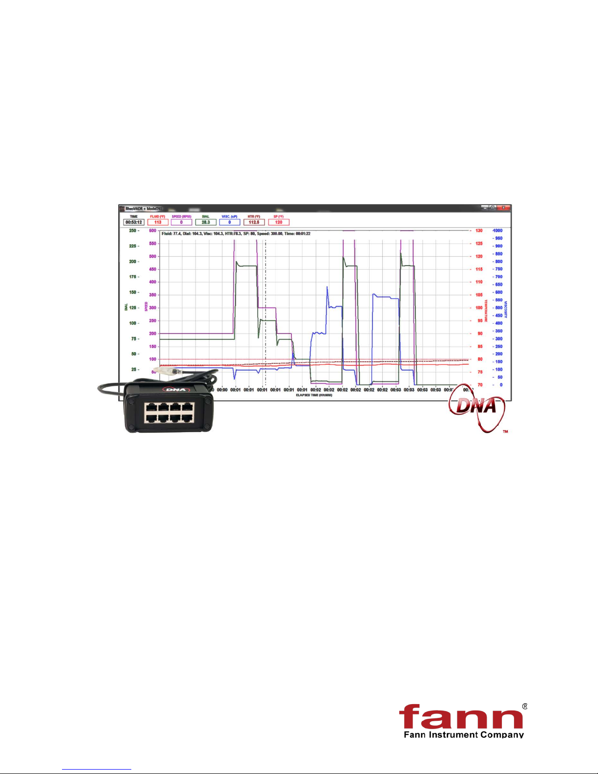
Figure 6-1 Graphical Results ........................................................................................ 39
Figure 8-1 DNA
System with RheoVADR®s and Temperature Controllers ................. 16
TM
Box .................................................................................................. 41
List of Tables
Table 3-1 Main Screen Menus and Functions .............................................................. 10
Table 3-2 Profile Screen Functions ............................................................................... 12
Table 7-1 Troubleshooting Guide .................................................................................. 40
Table 8-1 Data Network Adapter Assembly, P/N 102410489 ........................................ 41
D00981262 Revision A, May 2015 4

DNA
TM
System Instruction Manual
1 Introduction
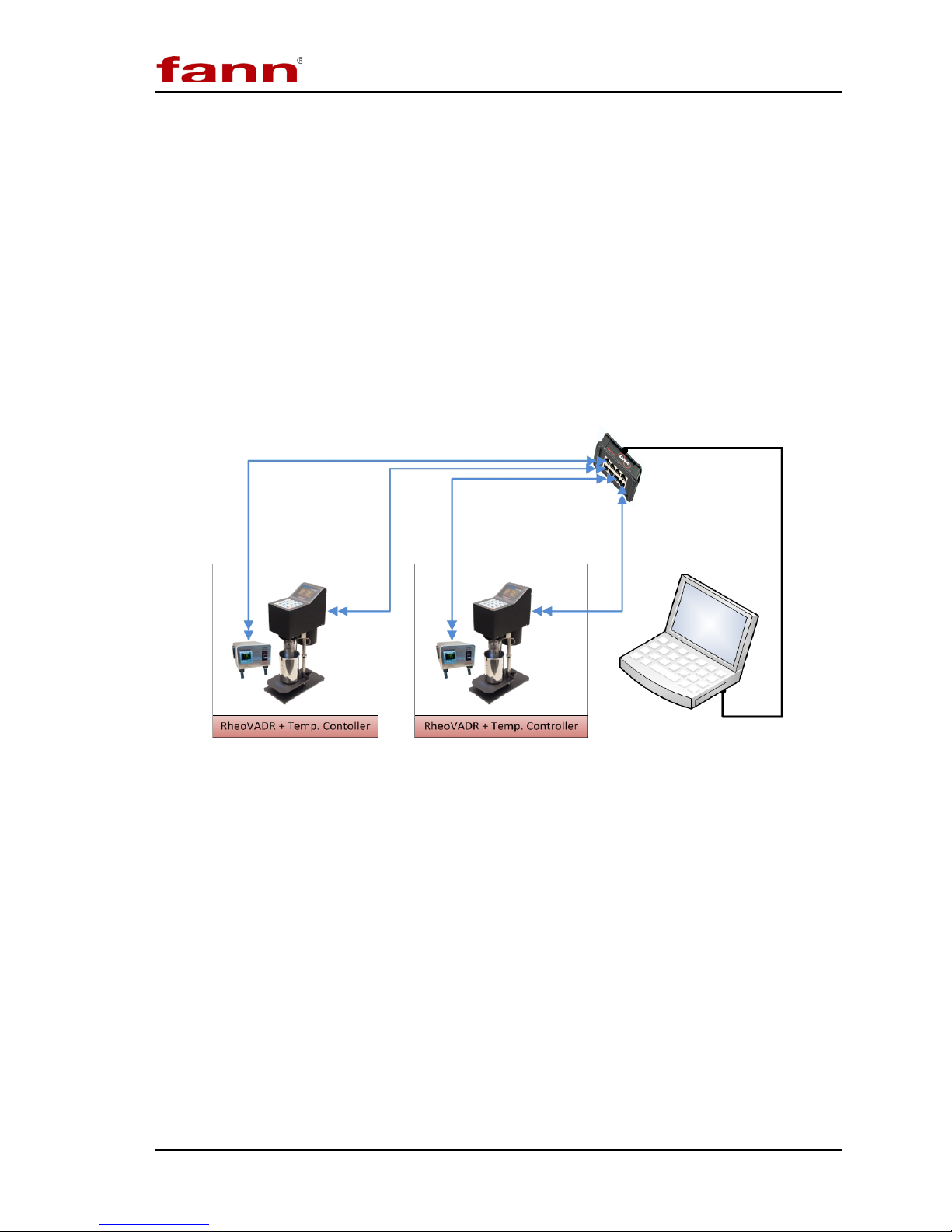
Fann® Data Network Adapter System is a proprietary hardware and software
system that adds capabilities to Fann instruments by connecting them to a computer
operating Fann’s exclusive Data Acquisition and Control software. The software
facilitates communication, control, and data collecting for up to eight machines.
Multiple units can be joined to act as an integrated system (e.g.,
RheoVADR® Rheometer with Model 741 Temperature Controller).
This system is ideal for users who want to
• automate several tests simultaneously and collect data for every test
• combine several machines to perform individual complex tests
1.1 Fann Equipment Compatible with DNATM System
The DNATM System works with RheoVADR® Rheometer, Model 741 Temperature
Controller, and HT4700 HPHT Filter Press. In the future, more Fann instruments
will be available for connecting to DNATM System.
D00981262 Revision A, May 2015 5
DNA
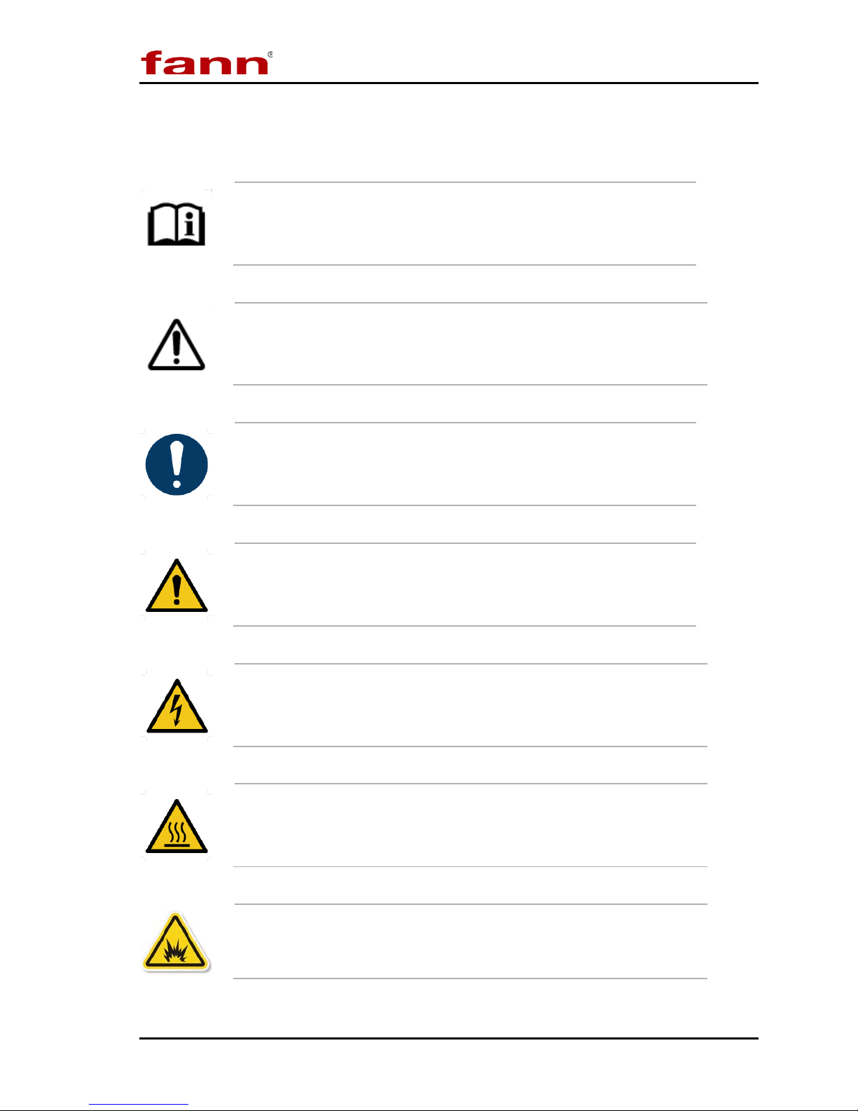
1.2 Document Conventions
The following icons are used as necessary in this instruction manual.
NOTE. Notes emphasize additional information that may be
useful to the reader.
CAUTION. Describes a situation or practice that requires operator
awareness or action in order to avoid undesirable consequences.
MAN D AT O R Y AC TION . Gives directions that, if not observed,
could result in loss of data or in damage to equipment.
TM
System Instruction Manual
WARNING! Describes an unsafe condition or practice that if not
corrected, could result in personal injury or threat to health.
ELECTRICITY WARNING! Alerts the operator that there is risk of
electric shock.
HOT SURFACE! Alerts the operator that there is a hot surface and
that there is risk of getting burned if the surface is touched.
EXPLOSION RISK! Alerts the operator that there is risk of
explosion.
D00981262 Revision A, May 2015 6
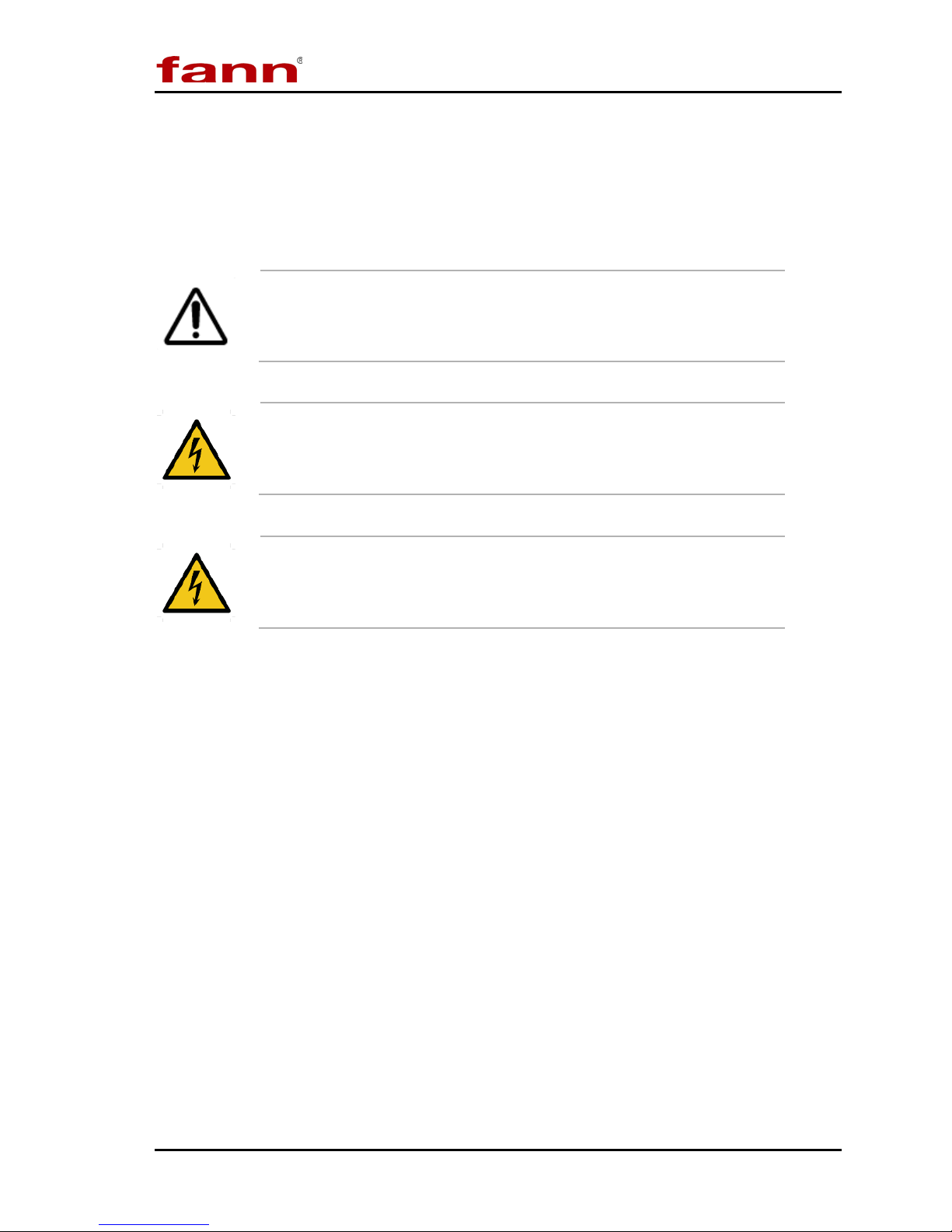
2 Safety
Safe laboratory practices and procedures should be observed while operating and
maintaining the DNATM system. This section lists some precautions to follow.
DNATM System Instruction Manual
Before runnng a test, review the safety precautions of connected
equipment (e.g., RheoVADR
Controller, and HT4700 Heating Jacket.).
®
Rheometer, Model 741 Temperature
DNATM should always be used on a grounded circuit.
Electrical connections to and from the DNATM box should be
properly insulated and must not be compromised.
D00981262 Revision A, May 2015 7
DNATM System Instruction Manual
3 Features and Specifications
The DNATM System includes the DNATM box (USB to RJ45) with USB computer
connector, software, and two 10-ft CAT5 RJ485 cables.
The box has ports for connecting eight individual machines or combinations of
machines (up to eight, maximum).
The DNATM System works with RheoVADR® Rheometer, Model 741
Temperature Controller, and HT4700 HPHT Filter Press. In the future, more
DNATM compatible instruments will be available from Fann.
Refer to Figure 3-1 for a typical setup:
Figure 3-1 DNA
TM
System Example Setup
3.1 System Features
• Combines units to act as one, increasing overall capabilities
• Schedules for time, temperature, speed, and data rate
• Provides temperature ramping
• Saves test profiles and combines profiles to run complex schedules
D00981262 Revision A, May 2015 8

DNATM System Instruction Manual
3.2 DNATM Software
The DNATM software offers the following features:
• Collects data from various instruments
• Controls several unique instruments
• Graphical display of set points, real-time values, elapsed time and more
variables
• Records data at 100 ms, 500 ms, 1 s, 2 s, 5 s, 10 s
• Audible alerts for end of test, temperature set point, and other important
steps or events
• Compatible with Fann Data Manager for organizing and printing data or
exporting it to a spreadsheet
• System updates available
• Operating system— Microsoft® Windows® 7
D00981262 Revision A, May 2015 9
DNA
Green = connected
Red = disconnected or an error
computer
Design test using steps, temperature,
recording rate, and speed
machine
Graph Scale
Adjust graph scale
Place cursor (vertical dotted line) on
graph to see values
Zoom Area
Set area on graph to view
Zoom In
Increase view
Zoom Reset
Change view to normal
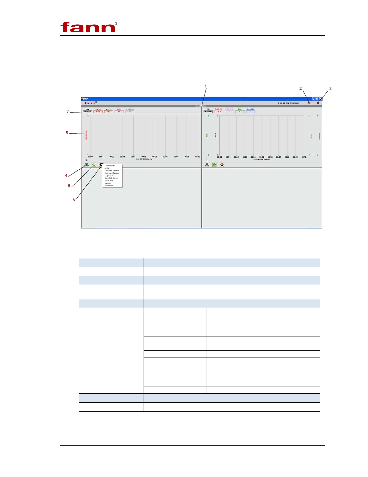
3.2.1 Main Screen
These menu items are described in detail in following sections.
TM
System Instruction Manual
Table 3-1 Main Screen Menus and Functions
1 Main Menu
2 Updates
3 Information
4 Connection Status
5 Start/Stop
6 Machine Settings
7 Indicators
8 Graph
Main Screen
Click to show more options
Check for software updates
Displays software version
Click to start (green) or stop (red).
Test File Path
Profile
Settings
Show/Hide Cursor
Displays real-time test data
Real-time graph d ispl a ys while test in progr ess
Location where files saved on your
Specify settings for each connected
D00981262 Revision A, May 2015 10
DNA
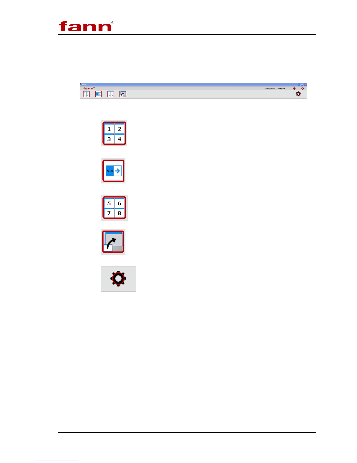
3.2.2 Main Menu Expanded
Click Main Menu to see the display options.
• shows machine windows 1, 2, 3, and 4.
• switches between display options – windows 1 to 4 or 5 to 8
TM
Main Menu Expanded View
System Instruction Manual
• shows machine windows 5, 6, 7, 8.
• expands the selected window for closer view.
• opens Settings (discussed in Section 4).
• Click the gray area to close the expanded view of the main menu.
3.2.3 System Updates
Click the update icon to check for new software versions. Then follow the
instructions shown to complete the update (Section 4).
D00981262 Revision A, May 2015 11
DNA
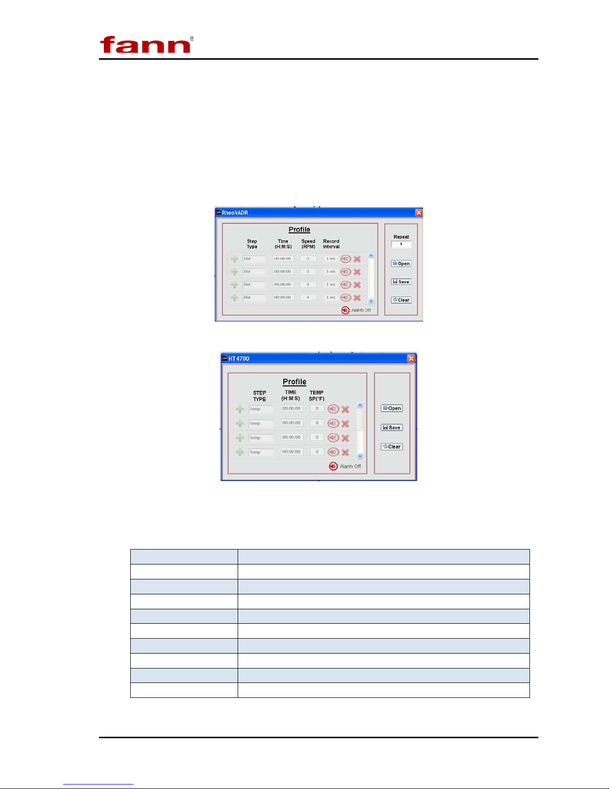
3.2.4 Profile Screen
Click Machine Settings gear (drop down). Select Profile.
Each machine has its own profile template. These illustrations show templates for
RheoVADR® Rheometer and HT4700 Filter Press.
Instructions for creating profiles are provided in Section 5.
RheoVADR® Profile
TM
System Instruction Manual
HT4700 Profile
Table 3-2 Profile Screen Functions
Step Type
Time
Speed
Record Interval
Temperature
Repeat
Open
Save
Clear
Alarm Click alarm icon to turn ON; click X to turn OFF
D00981262 Revision A, May 2015 12
Click the + to choose step type
Set time in hours, minutes, and seconds for step
Set speed (rpm); range 0.01 to 999.9 rpm
Enter recording rate: 100, 200 & 500 ms; 1, 5, & 10 sec
Enter set point temperature (degrees F or C)
Enter number of repeats for the profile
Open to select saved profiles
Save profiles for reuse
Erase entries
DNA
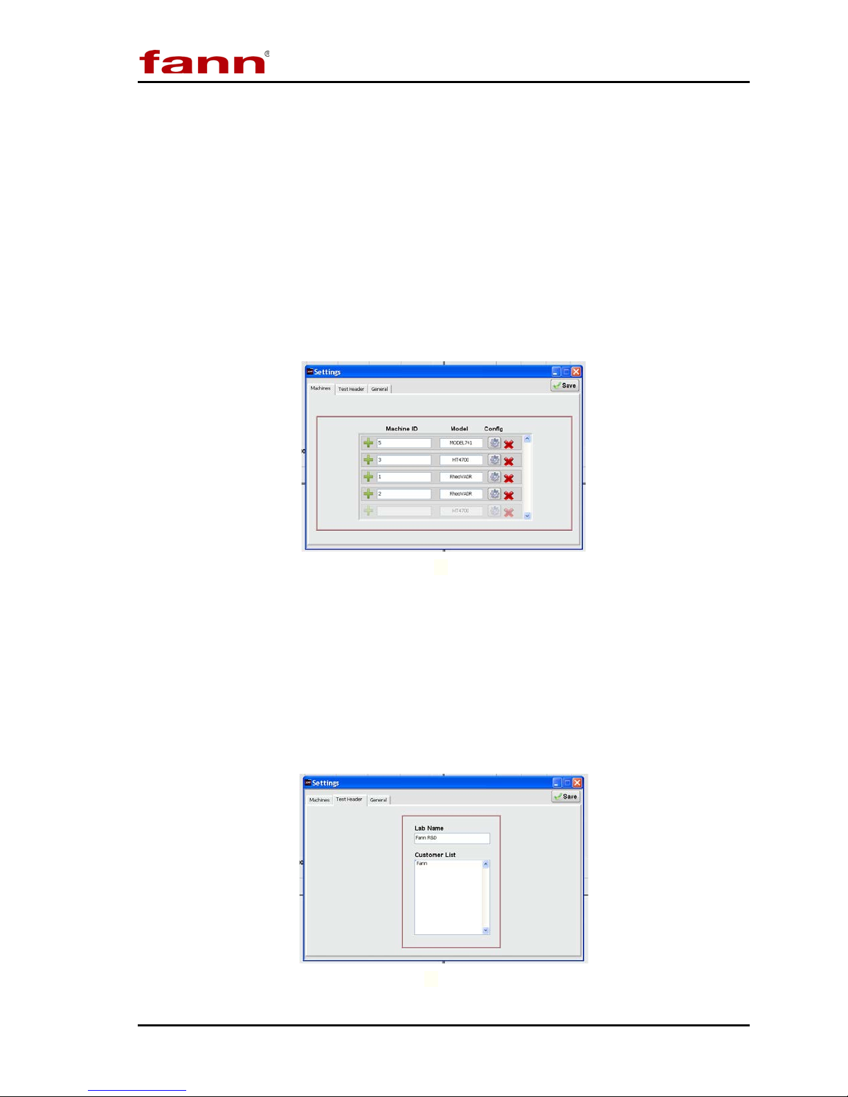
3.2.5 Settings Tabs
Machine
Assign a unique identification to each machine in the Machine ID box. Then,
select the model from the dropdown menu (Model 741 Temperature Controller,
RheoVADR® Rheometer, or HT4700 HPHT Filter Press).
To activate communication between the DNATM system and the machines,
configure each machine.
Click the configuration gear (Config) and follow the instructions. Detailed
configuration instructions are given in Section 4.
TM
System Instruction Manual
Settings Machine
Test Header
This section contains frequently used information— lab name and customer names.
The software will automatically fill (or prompt) certain fields when you set up your
tests. The lab name only needs to be entered once. During test setup, the software
will show this list of customers. New customer names are added to the bottom of
the list and sorted alphabetically when the OK button is clicked.
D00981262 Revision A, May 2015 13
SettingsTest Header
 Loading...