

Page 1
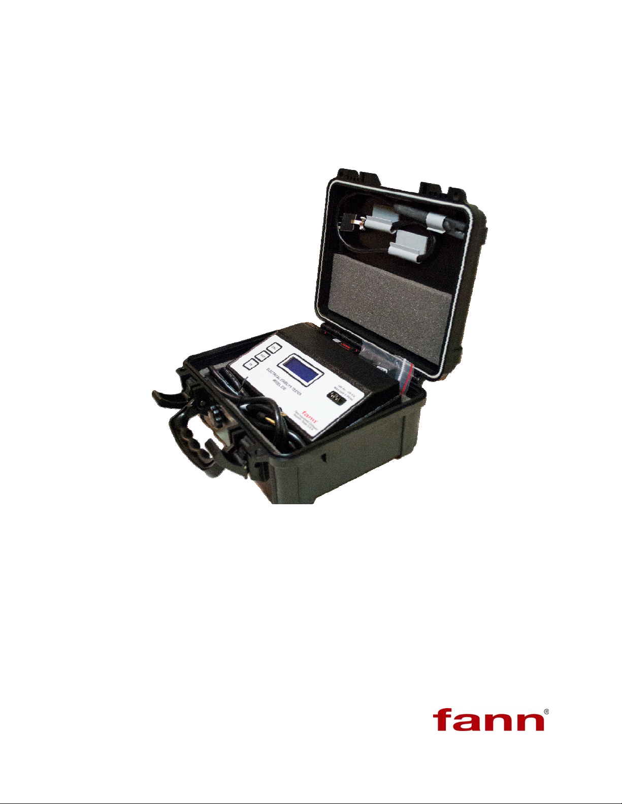
Electrical Stability Tester, Model 23E
Instruction Manual
Manual No. 102149576, Revision A, April 2012
Instrument No. 102130986
Fann Instrument Company
Page 2

Electrical Stability Tester Instruction Manual
©2012 Fann Instrument Company
Houston, Texas, USA
All rights reserved. No part of this work covered by the copyright hereon may be reproduced or
copied in any form or by any means (graphic, electronic, or mechanical) without first receiving the
written permission of Fann Instrument Company, Houston, Texas, USA.
Printed in USA.
The information contained in this document includes concepts, methods, and apparatus which may be
covered by U.S. Patents. Fann Instrument Company reserves the right to make improvements in
design, construction, and appearance of our products without prior notice.
®
FANN
States and/or other countries. All other trademarks mentioned in the operating instructions are the
exclusive property of the respective manufacturers.
and the FANN logo are registered trademarks of Fann Instrument Company in the United
Contact FANN
Phone
TELEPHONE: 281-871-4482
TOLL FREE: 800-347-0450
FAX: 281-871-4358
Mail
Fann Instrument Company
P.O. Box 4350
Houston, Texas, 77210 USA
Location
Fann Instrument Company
15112 Morales Rd Gate 7
Houston, Texas, 77032, USA
Online
www.fann.com
[email protected]
102149576 Revision A, 4/2012 2
Page 3

EST Model 23E Instruction Manual
Table of Contents
1 Introduction ................................................................................................................. 5
1.1 Electrical Stability Measurements ...................................................................... 5
1.2 Document Conventions ...................................................................................... 6
2 Safety ......................................................................................................................... 8
3 Features and Specifications ....................................................................................... 9
4 Equipment Setup ...................................................................................................... 12
5 Operations ................................................................................................................ 13
5.1 Self Test ........................................................................................................... 13
5.2 Test Procedure ................................................................................................. 13
6 Calibration Check ..................................................................................................... 17
6.1 Open Circuit Test ............................................................................................. 17
6.2 Self-Calibration ................................................................................................. 17
6.3 Calibration Standards ....................................................................................... 19
6.4 Probe Check .................................................................................................... 20
7 Troubleshooting and Maintenance ........................................................................... 21
7.1 Maintenance ..................................................................................................... 22
8 Accessories .............................................................................................................. 24
9 Warranty and Returns .............................................................................................. 25
9.1 Warranty ........................................................................................................... 25
9.2 Returns ............................................................................................................. 25
102149576 Revision A, 4/2012 3
Page 4

EST Model 23E Instruction Manual
List of Figures
Figure 3-1 Model 23E Electrical Stability Tester ............................................................... 9
Figure 3-2 Electrical Stability Tester (Rear View) ........................................................... 10
Figure 5-1 Self Test Mode ............................................................................................... 13
Figure 5-2 EST Probe immersed in sample .................................................................... 15
Figure 6-1 Open Circuit Test ........................................................................................... 17
Figure 6-2 Self Calibration Mode .................................................................................... 18
Figure 6-3 Sample Calibration Mode .............................................................................. 19
List of Tables
Table 3-1 Electrical Stability Tester, Model 23E Specifications ...................................... 11
Table 7-1 Troubleshooting Guide .................................................................................... 21
Table 8-1 Accessories ..................................................................................................... 24
102149576 Revision A, 4/2012 4
Page 5

EST Model 23E Instruction Manual
1 Introduction
The Fann Model 23E Electrical Stability Tester (EST) is a portable instrument that
measures the electrical stability (ES) of an oil-based drilling fluid. The drilling
fluid’s electrical stability relates to its emulsion stability and oil-wetting capability.
The ES Tester conforms to the electrical stability test procedure as describ ed in the
API Recommended Practice for Field Testing Oil-based Drilling Fluids, API RP
13B-2.
1.1 Electrical Stability Measurements
The electrical stability is measured by applying a steadily increasing sinusoidal
alternating voltage across a pair of parallel flat plate electrodes submerged in the
oil-based drilling fluid. The resulting current will remain very low until a threshold
voltage is reached. At this voltage, conduction between the two electrodes occurs,
resulting in a rapid increase in current. When this current reaches 61µA, the peak
voltage is measured and reported as the electrical stability for the drilling fluid or
other material.
The composition of the oil-based drilling fluid controls the absolute magnitude of
electrical stability in a complex fashion. Several properties influence the electrical
stability of a given drilling fluid, such as
Resistivity of the continuous phase (typically an oil)
Conductivity of the non-continuous phase (typically water droplets with
dissolved salts)
Properties of suspended solids
Temperature
Droplet size
Type of emulsifier
Dielectric properties of the fluids
Shear history of the sample
Consequently, interpreting the oil-wet state of a drilling fluid from a single ES
measurement is not necessarily representative of the drilling fluid. Because many
factors influence the measurement, the absolute magnitude of a single measurement
is not very meaningful. It is recommended that several readings be taken to
establish a trend. These measurements will reflect an accurate condition of the
drilling fluid and provide a basis for drilling fluid treatments.
102149576 Revision A, 4/2012 5
Page 6
EST Model 23E Instruction Manual
The Model 23E is calibrated in peak volts which is the maximum voltage that the
fluid experiences between the two electrodes. Peak voltage may be converted to
root mean square (RMS) voltage by multiplying the peak voltage by 0.7071 if
desired.
The electrical stability measurement has been standardized for the size, spacing of
the electrodes, and current flow (considered as conduction of the fluid). The two
electrodes are equal size and are spaced 0.061 in (0.155 cm) apart. The current
value (conducting current) is set to 61µA. An alternating voltage of a constant
frequency (340 Hz ±10 Hz) and a steadily increasing sinusoidal voltage are applied
across the electrode. When the fluid between the immersed electrodes starts to
conduct and conduction increases to 61 µA, the voltage ramp automatically stops
and the peak voltage reading becomes stable. At that point, the peak voltage is read
and reported as the dielectric breakdown voltage.
1.2 Document Conventions
The following icons are used as necessary to distinguish elements of text.
NOTE. Notes emphasize additional information that may be
useful to the reader.
CAUTION. Describes a situation or practice that requires operator
awareness or action in order to avoid undesirable consequences.
MANDATORY ACTION. Gives directions that, if not observed,
could result in loss of data or in damage to equipment.
WARNING! Describes an unsafe condition or practice that if not
corrected, could result in personal injury or threat to health.
102149576 Revision A, 4/2012 6
Page 7
EST Model 23E Instruction Manual
ELECTRICITY WARNING! Alerts the operator that there is risk of
electric shock.
HOT SURFACE! Alerts the operator that there is a hot surface and
that there is risk of getting burned if the surface is touched.
102149576 Revision A, 4/2012 7
Page 8
EST Model 23E Instruction Manual
2 Safety
Safe laboratory practices and procedures should be observed while operating and
maintaining the EST. Some test samples can be potentially hazardous or contain
flammable materials. Use good ventilation and laboratory hoods when working
with these samples.
The Model 23E Electrical Stability Tester is powered by two 9V batteries or AC
(100-240V, 50/60 Hz). When the unit is operating on AC power, a circuit breaker
will trip and shutdown the unit if a complete short occurs or the unit draws
uncontrolled power.
The EST probe carries voltage power as high as 2000V. Do NOT
touch the probe while testing is in progress.
The user should keep the probe away from electrical ground terminals.
Use care when testing water-based fluids. The probe must be immersed in the
sample before the test is started.
Do NOT start the test and then immerse the probe into the sample
because sudden breakdown of the fluid may cause current that is
greater than 61µA to flow through the circuit.
102149576 Revision A, 4/2012 8
Page 9
EST Model 23E Instruction Manual
y
3 Features and Specifications
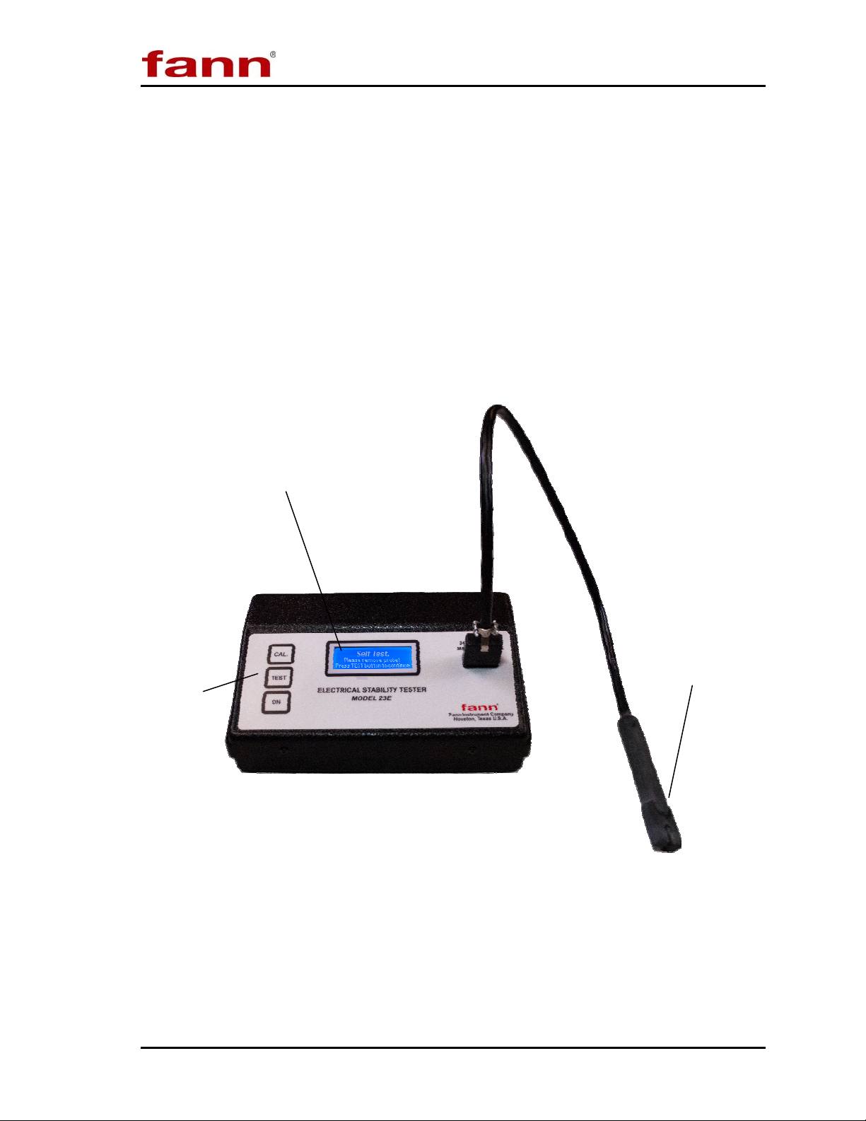
The Fann Model 23E Electrical Stability Tester (EST) is a battery or AC-powered,
portable instrument which conforms to the electrical stability test procedure
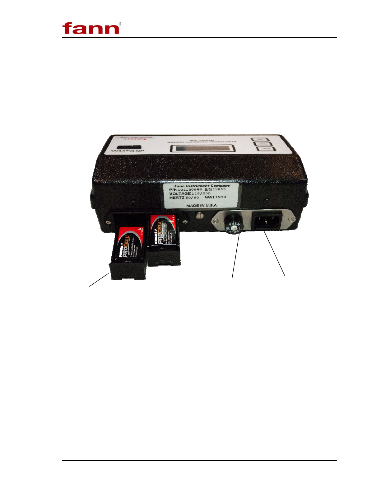
described in API RP 13B-2. See Figure 3-1 (front view) and Figure 3-2 (back
view).
The components include the testing unit (electronics), an electrode probe, two
calibration standards, a power cord, batteries, and a plastic carrying case.
The specifications are listed in Table 3-1.
Voltage and Message Displa
Keypad
Detachable Probe
Figure 3-1 Model 23E Electrical Stability Tester
102149576 Revision A, 4/2012 9
Page 10
EST Model 23E Instruction Manual
r
r
9 Volt Battery Holde
Circuit Breake
Figure 3-2 Electrical Stability Tester (Rear View)
AC Power Cord Socket
102149576 Revision A, 4/2012 10
Page 11

EST Model 23E Instruction Manual
Table 3-1 Electrical Stability Tester, Model 23E Specifications
Category Specification
Operating Temperature Range 32oF to 122oF (0 oC to 50oC)
Maximum Probe Temperature 300oF (149oC)
o
-4
Storage Temperature Range
Accuracy ± 2% of Expected Reading
Time before Auto Power Off 3 minutes
Output Frequency 340 Hz ± 2 Hz
Output Wave Form Sinusoidal, <1% total harmonic distortion
F to 158oF (-20oC to 70oC)
(without batteries)
Output Voltage Range
Breakdown Peak Output Current 61 µA
Peak Volts Readout Backlit Digital LCD
Voltage Ramp Rate 150 ± 10 V/sec
Power Supply
Battery Life Approximately 250 tests
Probe and Cable Length 24 in. (61 cm)
Probe Electrode Spacing 0.061in. (0.155cm)
Meter Dimensions
(Width x Depth x Height)
Weight 4 lb (1.8 kg)
0 V to 2025 V ± 25 V peak to ground
(1432 Volts RMS)
Two, 9 Volt alkaline batteries
100-240 VAC, 50/60 Hz, 10 watts
8.3 x 5.1 x 2.8 in.
21 x 13 x 7.1 cm
102149576 Revision A, 4/2012 11
Page 12

EST Model 23E Instruction Manual
4 Equipment Setup
The Model 23E EST should be placed in a position where there is easy access to
the AC power outlet if operating with AC power.
Consideration should also be given to the location where samples are prepared and
equipment is cleaned when the test is completed. There should be sufficient storage
area nearby for commonly used tools, as well as consumables.
In addition to the Model 23 EST, you will also need the following equipment to
perform an electrical stability test:
12-mesh screen or Marsh Funnel
Thermometer, 32
Glass beaker or viscometer sample cup (heating cup)
o
F to 220oF (0oC to 104oC)
Hot plate or heating source
102149576 Revision A, 4/2012 12
Page 13
EST Model 23E Instruction Manual
5 Operations
5.1 Self Test
The first check that the instrument performs is the Self Test.
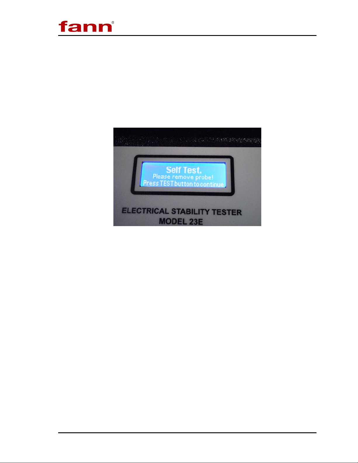
1. Push the ON button. Wait for the following messages to appear (Figure 5-1).
Figure 5-1 Self Test Mode
2. Follow the instructions on the screen: a) remove the probe if it is connected; b)
press the TEST button.
3. Wait for the Self Test to complete. The voltage will ramp to approximately
2000 volts, and then the screen message will say “READY.” The instrument is
ready for your samples.
5.2 Test Procedure
The following test procedure is in accordance with API Recommended Practice for
Field Testing Oil-based Drilling Fluids, API RP 13B-2.
Before starting the test, verify that the Electrical Stability Tester is calibrated and
operating properly. Refer to Section 6 for calibration instructions and Section 7 for
troubleshooting and maintenance.
1. Pour the sample over a 12 mesh screen to remove large solids. A laboratory sieve
or a Marsh Funnel can be used.
102149576 Revision A, 4/2012 13
Page 14

EST Model 23E Instruction Manual
2. Put the sample in a glass beaker or viscometer sample cup. The sample will be
heated.
3. Heat the sample and maintain the temperature at 50C ± 2C (120F ± 5F).
Do NOT connect the electrode probe to the instrument.
4. Clean the electrode body thoroughly with a paper towel. Pass the paper towel
through the electrode gap a few times.
5. Swirl the electrode probe in the base oil that was used to formulate the drilling
fluid. If the base oil is not available, use another oil or a mild solvent (e.g.,
isopropanol). Clean and dry the electrode.
Do NOT use detergent solutions or aromatic solvents, such as
xylene to clean the electrode probe or cable.
6. Push the ON button to start the instrument electronics. Next, the instrument will
require you to run the Self Test. Complete the Self Test.
There is no OFF button. The instrument shuts itself off
approximately three minutes after the last operation.
7. Now, connect the electrode to the instrument.
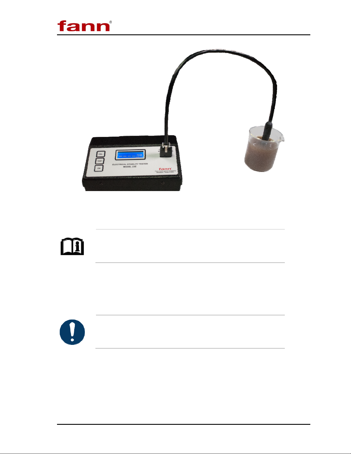
8. Immerse the probe in the sample, making certain that the fluid covers the
electrode surfaces. See Figure 5-2.
102149576 Revision A, 4/2012 14
Page 15
EST Model 23E Instruction Manual
Figure 5-2 EST Probe immersed in sample
Make sure that the probe does not touch the sides or bottom of
the container.
9. Stir briskly with the probe for at least 10 seconds making sure that the sample
temperature is 50C ± 2C (120F ± 5F). Use a thermometer to measure the
temperature.
Do NOT move the electrode probe during the measurement.
10. Push and release the TEST button to start the automatic voltage ramp. Do not
move the electrode probe during the measurement. The ramp will stop at the
breakdown voltage. Record this reading as the dielectric breakdown voltage
(electrical stability reading).
102149576 Revision A, 4/2012 15
Page 16

EST Model 23E Instruction Manual
If the instrument reading ramps to greater than 2000 volts and
dashed lines flash on the screen, the sample breakdown voltage
is greater than 2025 V ± 25 V (peak).
11. Determine the repeatability of the test. Repeat steps 4 through 9. The electrical
stability readings should not differ by more than 5%. For example, with an initial
electrical stability of 900 peak volts, the repeated test should range within
855 volts to 945 volts (5 % of 900 peak volts = 45 peak volts).
12. Record the average of the two (or more) readings as the electrical stability of the
oil-based drilling fluid.
The instrument holds the last reading. You may press the TEST
button again to reset the reading and start another test.
13. If the readings differ by more than 5%, perform troubleshooting and maintenance
on the instrument as described in Section 7.
102149576 Revision A, 4/2012 16
Page 17
EST Model 23E Instruction Manual
6 Calibration Check
A standard fluid is not available to test the performance of both the Model 23E and
its electrode. However, performance checks can be done on the instrument and the
electrode separately.
6.1 Open Circuit Test
1. Unplug the probe from the instrument.
2. Press the ON button, and then run the Self Test as described in Section 5.1.
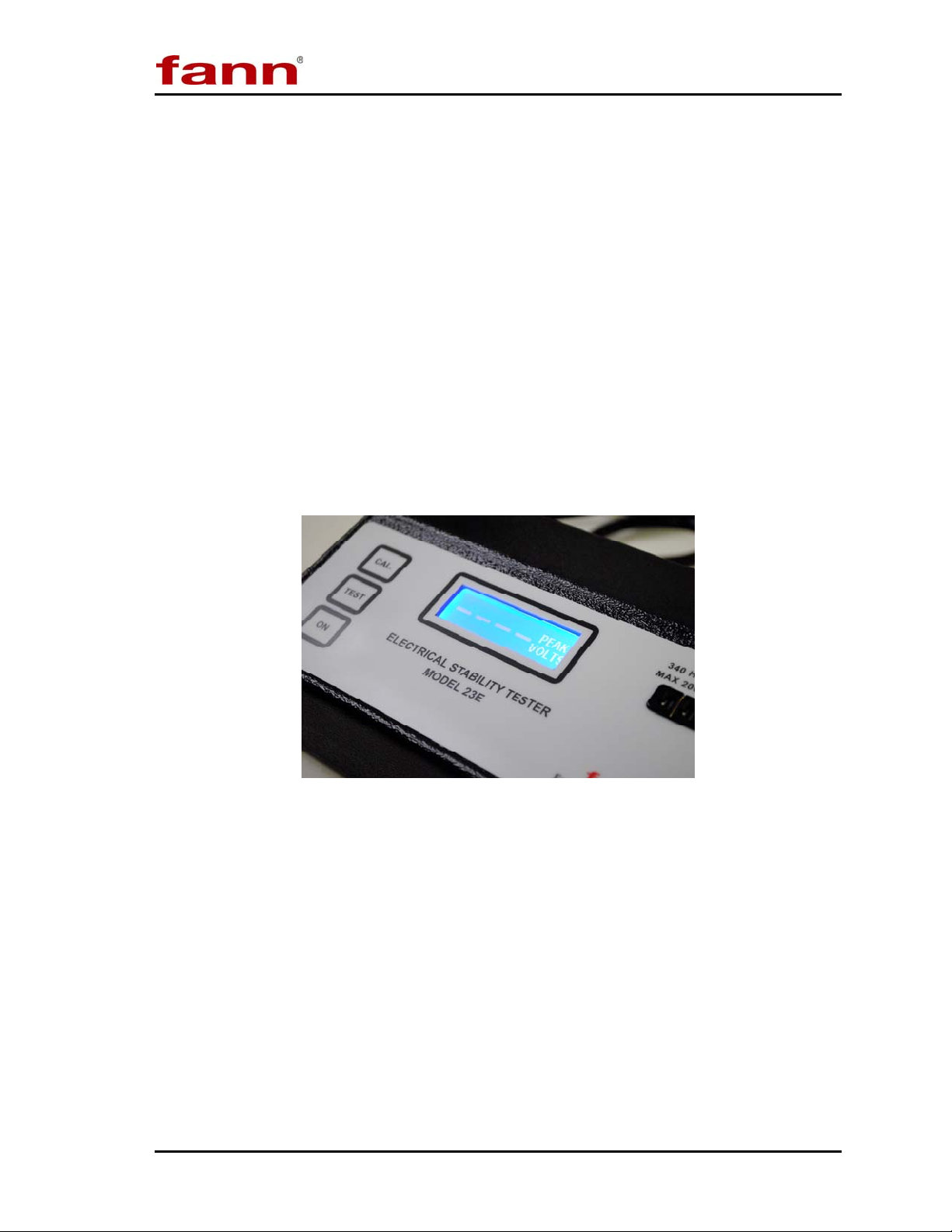
3. Next, press the TEST button. The voltage reading should increase to more than
2000 volts, and then a dashed line will flash on the screen to indicate the reading
is over range as shown in Figure 6-1. If it does not, see Section 7 for trouble
shooting.
Figure 6-1 Open Circuit Test
6.2 Self-Calibration
The Model 23E has a self-calibration feature. You should regularly perform a selfcalibration test, especially when the readings from the calibration standards are
greater than 2%.
1. Press the ON button. Run the Self Test, following the instructions on the
screen. Refer to Section5.1.
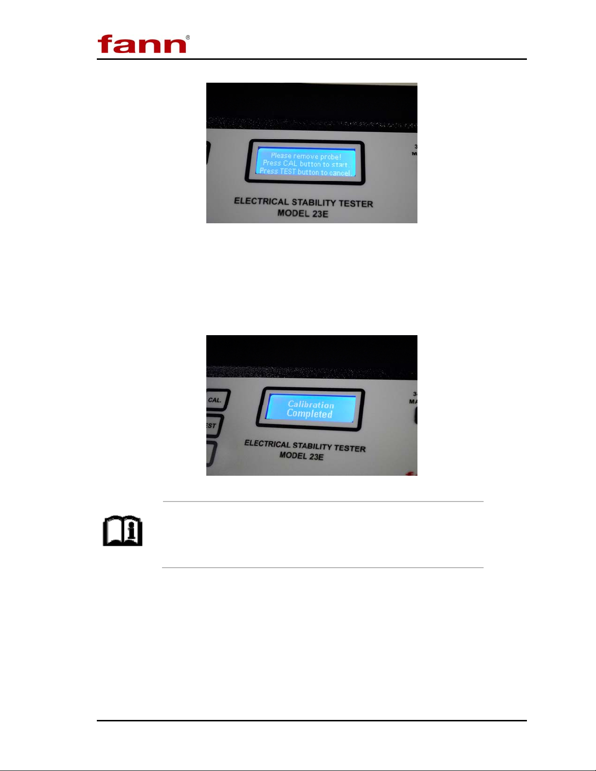
2. Press CAL. Remove the probe and then press CAL again. These instructions
will also appear on the screen as shown in Figure 6-2.
102149576 Revision A, 4/2012 17
Page 18
EST Model 23E Instruction Manual
Figure 6-2 Self Calibration Mode
3. The calibration is in progress when the voltage ramps up to approximately
1200 V. Wait for the voltage to ramp up twice; after the first ramp, there will be
a brief pause and the calibration process will repeat. Then a message will
appear, “Calibration Completed.” Now, the instrument is ready for your tests.
End of Self Calibration
If the instrument display reads, “Calibration Fail” or “Calibration
Unstable,” then repeat the self-calibration procedure. If the
problem persists, contact Fann Instrument Company for
assistance.
102149576 Revision A, 4/2012 18
Page 19
EST Model 23E Instruction Manual
6.3 Calibration Standards
Two calibration standards are supplied with the instrument— high range and low
range. Each standard is marked with the reading expected from the instrument.
Fann Instrument Company makes the calibration standards and
tests them for voltage. Each calibration standard has a unique
voltage reading.
1. Push the ON button to start the instrument electronics. Complete the Self Test.
2. Insert one of the calibration standards into the probe socket in place of the probe.
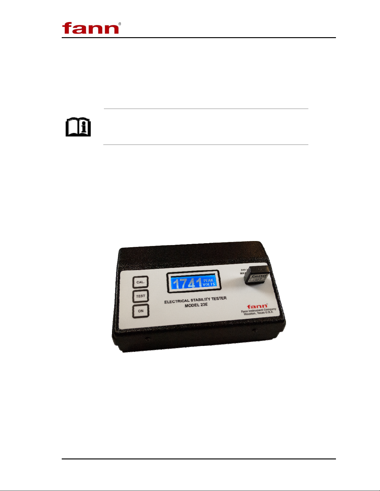
3. Then push and release the TEST button to start the automatic voltage ramp. The
instrument should ramp as if a test is being run. It should stop ramping when the
voltage reaches within 2% of the standard calibration voltage. See Figure 6-3;
the calibration standard in this figure is 1757 volts and the actual reading is 1741.
Figure 6-3 Sample Calibration Mode
4. Repeat steps 2 and 3 using the other calibration standard.
5. If the instrument does not read peak voltage of the calibration standards within
2% of the standard calibration voltage, then perform the self-calibration (Section
6.2) and repeat the manual calibration. If the problem persists, then either the
calibration standards or the equipment is malfunctioning. Contact Fann
Instrument Company for assistance.
102149576 Revision A, 4/2012 19
Page 20

EST Model 23E Instruction Manual
6.4 Probe Check
Before checking the probe, check the EST calibration as provided in Section 6.1,
6.2 and 6.3. Then, test the Model 23E probe as follows:
1. Unplug the probe from the instrument.
2. Inspect the probe cable for cracks in its insulation or other damage.
3. Make sure that the probe has been thoroughly cleaned. Examine the keyhole-
shaped gap in the electrode for any deposits.
4. Also examine the three pins on the plug (at the end of the probe cable) for
moisture or deposits.
5. Confirm that the space between the electrodes of the probe is approximately
0.155 cm to 0.160 cm (0.061 in. to 0.063 in.). You can use a 1/16-in drill bit
shank as a gauge.
6. Plug the probe into the EST. Hold the dry probe in the air and press the TEST
button. The peak voltage should ramp to > 2000 volts (flashing dashed line). If it
does not, then an electrical path exists between the two electrodes by some means
other than through the fluid. Clean the plug and the electrode end of the probe,
and then test it again. If the probe continues to fail the test, replace it.
7. Immerse the probe into fresh tap water and run a test. The electrical stability
reading should read less than 3 volts. A reading greater than 3 volts means that
something is insulating the electrodes and keeping them from contacting the
fluid. It may also mean that the probe wiring is damaged. Clean the surface of
the electrodes and the plug pins. Dry the probe carefully, and then test again. If
the probe continues to fail this test, then replace it.
8. If the electrode probe does not pass these steps, then the probe has probably
failed internally and should be replaced. Contact Fann Instrument Company for
a replacement.
102149576 Revision A, 4/2012 20
Page 21

EST Model 23E Instruction Manual
7 Troubleshooting and Maintenance
Troubleshooting and regular maintenance procedures are described in this section.
If more extensive maintenance or service of the instrument is required, please
contact Fann Instrument Company.
Table 7-1 Troubleshooting Guide
Problem or Symptom Possible Cause Corrective Action
Does not activate when the
Missing or weak batteries. Replace the batteries.
ON button is pressed.
Did not firmly press the ON
button.
Press the button again with
more pressure.
LOW BATTERY message. Weak batteries. Replace the batteries.
Clean and thoroughly dry
connector pins.
Replace them.
Repeat self-calibration. If
problem persists, return the
Voltage readings obtained
with calibration standards
are incorrect.
Dirty calibration standards.
Damaged calibration
standards.
Out of calibration.
instrument to Fann.
Probe does not pass the
performance check.
ES Tester does not read
> 2000 volts (flashing
Probe failure. Replace the probe.
The connector is
contaminated with
conductive deposits.
Clean and thoroughly dry
the connector.
dashed line) when a probe
is not connected.
Internal calibration loss.
Perform self calibration and
try again.
Self calibration gives
message, “CALIBRATION
FAIL.”
Self calibration gives
message “CALIBRATION
UNSTABLE.”
Instrument failure.
Internal calibration loss.
Return the instrument to
Fann for repair.
Perform self calibration
again.
102149576 Revision A, 4/2012 21
Page 22

EST Model 23E Instruction Manual
7.1 Maintenance
The following information will help ensure accurate reliable operation of the
Model 23E.
7.1.1 Cleaning and Protecting the Instrument
The Fann Model 23E Electrical Stability Tester will work reliably for a long time if
kept clean— free of dirt, corrosive fluids, and solvents. Be especially careful to
avoid exposing the instrument to fluid spills into the probe connector or into the
battery compartments. Although the carrying and shipping case is watertight, the
instrument case is not.
Avoid rough handling of the instrument.
Clean the electrode body thoroughly by wiping with a clean paper towel. Pass the
towel through the electrode gap a few times. Pass the towel through the electrode
gap a few times to clean and dry the electrode.
Do NOT use detergent solutions or aromatic solvents, such as
xylene to clean the electrode probe or cable.
The instrument case and its carrying case can be cleaned with a cloth or sponge
dampened with a mild detergent.
102149576 Revision A, 4/2012 22
Page 23
EST Model 23E Instruction Manual
7.1.2 Replacing the Batteries
Replace batteries using the following procedure.
Proper installation is important. Place the batteries in the drawers
with the terminals as shown in the bottom of the drawer.
1. Battery life should be adequate for approximately 250 tests. Battery life will be
less if the average breakdown voltages are greater than 1000 volts.
2. Remove both batteries if the instrument will be stored for a long time or if the
instrument will be used with AC power for a long time.
When batteries are left unused for a long time, they may leak and
cause corrosion damage to the instrument.
3. Replace the batteries with fresh 9 volt alkaline batteries (P/N 205643) or
equivalent whenever the LOW BATTERY message comes on.
4. The battery holders are on the back of the EST. Lift and remove the battery
holders. Remove the used batteries. Place the new batteries in the holders. Put
the battery holders back into the EST. Refer to Figure 3-2.
The instrument may be operated with AC power. The required AC power is
100-240 VAC, 50/60 Hz, 10 watts.
7.1.3 Storing Calibration Standards
Calibration standards should be kept clean of anything that might form a
conductive film or deposit between the pins of the plug. Avoid exposing these
standards to moisture, especially salty atmospheres. Store these standards in sealed
plastic bags or a sealed jar.
102149576 Revision A, 4/2012 23
Page 24

EST Model 23E Instruction Manual
8 Accessories
Part Number Description
208557 EST Probe
209066 Calibration Standard Set
209067 Calibration Standard, High Range
209068 Calibration Standard, Low Range
Table 8-1 Accessories
102149576 Revision A, 4/2012 24
Page 25

EST Model 23E Instruction Manual
9 Warranty and Returns
9.1 Warranty
Fann Instrument Company warrants its products to be free from defects in material
and workmanship for a period of 12 months from the time of shipment. If repair or
adjustment is necessary, and has not been the result of abuse or misuse within the
twelve-month period, please return, freight prepaid, and correction of the defect
will be made without charge.
Out of warranty products will be repaired for a nominal charge.
Please refer to the accompanying warranty statement enclosed with the product.
9.2 Returns
For your protection, items being returned must be carefully packed to prevent
damage in shipment and insured against possible damage or loss. Fann will not be
responsible for damage resulting from careless or insufficient packing.
Before returning items for any reason, authorization must be obtained from Fann
Instrument Company. When applying for authorization, please include information
regarding the reason the items are to be returned.
Our correspondence address is:
Fann Instrument Company
P.O. Box 4350
Houston, Texas USA 77210
Telephone: 281-871-4482
Toll Free: 800-347-0450
FAX: 281-871-4446
15112 Morales Road
Gate 7, Houston, Texas USA 77032
102149576 Revision A, 4/2012 25
 Loading...