

fann 35A, 35SA, 35A/SR-12, 35SA/SR-12 Instruction Manual
Model 35 Viscometer
Instruction Manual
Models 35A, 35SA, 35A/SR-12, and 35SA/SR-12
Manual No. 208878, Revision N

Model 35 Instruction Manual
©2013 Fann Instrument Company
Houston, Texas, USA
All rights reserved. No part of this work covered by the copyright hereon may be reproduced or
copied in any form or by any means (graphic, electronic, or mechanical) without first receiving the
written permission of Fann Instrument Company, Houston, Texas, USA.
Printed in USA.
The information contained in this document includes concepts, methods, and apparatus
which may be covered by U.S. Patents. Fann Instrument Company reserves the right to
make improvements in design, construction, and appearance of our products without prior
notice
®
FANN
States and/or other countries. All other trademarks mentioned in the operating instructions are the
exclusive property of the respective manufacturers.
and the FANN logo are registered trademarks of Fann Instrument Company in the United
Contact FANN
Phone
TELEPHONE: 281-871-4482
TOLL FREE: 800-347-0450
FAX: 281-871-4358
Mail
Fann Instrument Company
P.O. Box 4350
Houston, Texas, 77210 USA
Location
Fann Instrument Company
15112 Morales Rd Gate 7
Houston, Texas, 77032, USA
Online
www.fann.com
fannmail@fann.com
208878 Revision N, February 2013 2

Model 35 Viscometer Instruction Manual
Table of Contents
1 Introduction ............................................................................................................... 5
1.1 Background ...................................................................................................... 5
1.2 Document Conventions .................................................................................... 6
2 Safety ....................................................................................................................... 7
2.1 Safe Electrical Operation .................................................................................. 7
2.2 Standard B1 Bob .............................................................................................. 8
2.3 Heated Sample Cup ......................................................................................... 8
3 Features and Specifications ...................................................................................... 9
4 Installation .............................................................................................................. 13
5 Operation ................................................................................................................ 14
5.1 Operating the Model 35A and 35SA ............................................................... 15
5.2 Operating the Model 35A/SR-12 and 35SA/SR-12.......................................... 15
5.3 Measuring Gel Strength .................................................................................. 17
5.4 Changing the Rotors, Bobs, and Torsion Springs ........................................... 18
6 Instrument Calibration Check .................................................................................. 23
6.1 Dead Weight Calibration ................................................................................. 24
6.2 Fluid Calibration Check ................................................................................... 26
6.3 Torsion Spring Calibration .............................................................................. 27
7 Test Analysis .......................................................................................................... 28
7.1 Newtonian Viscosity Calculation ..................................................................... 28
7.2 Plastic Viscosity and Yield Point Calculation ................................................... 29
7.3 Spring Constant Calculation ........................................................................... 30
7.4 Additional Viscosity Calculations ..................................................................... 31
7.5 Measuring Ranges .......................................................................................... 33
8 Troubleshooting and Maintenance .......................................................................... 36
8.1 Troubleshooting .............................................................................................. 36
8.2 Maintenance ................................................................................................... 37
9 Accessories ............................................................................................................ 38
10 Parts List................................................................................................................. 39
11 Warranty and Returns ............................................................................................. 44
11.1 Warranty ......................................................................................................... 44
11.2 Returns ........................................................................................................... 44
208878 Revision N, February 2013 3

Model 35 Viscometer Instruction Manual
List of Figures
Figure 3-1 Model 35SA Viscometer ................................................................................. 9
Figure 3-2 Model 35 Viscometer Schematic .................................................................. 10
Figure 5-1 Gear Box Shift Lever .................................................................................... 16
Figure 5-2 Rotor Removal and Installation .................................................................... 19
Figure 5-3 Bob and Bob Shaft ....................................................................................... 20
Figure 5-4 Torsion Spring Removal and Replacement .................................................. 22
Figure 6-1 DW3 Calibration Fixture ............................................................................... 24
Figure 10-1 Model 35A and 35SA - Upper ..................................................................... 40
Figure 10-2 Model 35A and 35SA – Lower .................................................................... 41
List of Tables
Table 3-1 Model 35 Viscometer Specifications .............................................................. 11
Table 3-2 Model 35 Viscometer Sizes ........................................................................... 11
Table 3-3 Rotor and Bob Dimensions ............................................................................ 12
Table 3-4 Rotor-Bob Specifications ............................................................................... 12
Table 3-5 Range of Environmental Conditions .............................................................. 12
Table 5-1 Six-Speed Testing Combinations for Models 35A and 35SA ......................... 15
Table 5-2 Twelve-Speed Testing Combinations- Models 35A/SR-12 and 35SA/SR-12 . 16
Table 6-1 Dial Deflection for Calibration Weights and Torsion Spring Assemblies ......... 25
Table 7-1 Rotor-Bob Factor (C) ..................................................................................... 29
Table 7-2 Speed Factor (S) ........................................................................................... 29
Table 7-3 Torsion Spring Specifications ........................................................................ 30
Table 7-4 Constants for Viscosity Calculations .............................................................. 32
Table 7-5 Conversion Factors ....................................................................................... 32
Table 7-6 Shear Stress Measuring Range for Fann Direct Indicating Viscometer .......... 33
Table 7-7 Shear Rate Measuring Range for Fann Direct Indicating Viscometers .......... 34
Table 7-8 Viscosity Range in Centipoise for Fann Direct Indicating Viscometers .......... 35
Table 8-1 Troubleshooting Guide .................................................................................. 36
Table 9-1 Accessories ................................................................................................... 38
Table 10-1 Model 35 Series Viscometers ...................................................................... 39
Table 10-2 Model 35 Series Viscometer Parts List ........................................................ 42
208878 Revision N, February 2013 4

Model 35 Viscometer Instruction Manual
1 Introduction
Fann Model 35 viscometers are direct-reading instruments which are available in
six- speed and twelve- speed designs for use on either 50 Hz or 60 Hz electrical
power. The standard power source is 115 volts, but all models may be fitted with a
transformer, making operation with 220/230 volts possible.
Fann Model 35 viscometers are used in research and production. These viscometers
are recommended for evaluating the rheological properties of fluids, Newtonian
and non-Newtonian. The design includes a R1 Rotor Sleeve, B1 Bob, F1 Torsion
Spring, and a stainless steel sample cup for testing according to American
Petroleum Institute Recommended Practice for Field Testing Water Based Drilling
Fluids, API RP 13B-1/ISO 10414-1 Specification.
1.1 Background
Fann Model 35 viscometers are Couette rotational viscometers. In this viscometer,
the test fluid is contained in the annular space (shear gap) between an outer cylinder
and the bob (inner cylinder). Viscosity measurements are made when the outer
cylinder, rotating at a known velocity, causes a viscous drag exerted by the fluid.
This drag creates a torque on the bob, which is transmitted to a precision spring
where its deflection is measured.
Viscosity measured by a Couette viscometer, such as the Model 35, is a measure of
the shear stress caused by a given shear rate. This relationship is a linear function
for Newtonian fluids (i.e., a plot of shear stress vs. shear rate is a straight line).
The instrument is designed so that the viscosity in centipoise (or millipascal
second) of a Newtonian fluid is indicated on the dial with the standard rotor R1,
bob B1, and torsion spring F1 operating at 300 rpm. Viscosities at other test speeds
may be measured by using multipliers of the dial reading. A simple calculation that
closely approximates the viscosity of a pseudo-plastic fluid, such as a drilling fluid
is described in Section 7.
The shear rate may be changed by changing the rotor speed and rotor-bob
combination. Various torsion springs are available and are easily interchanged in
order to broaden shear stress ranges and allow viscosity measurements in a variety
of fluids.
208878 Revision N, February 2013 5
Model 35 Viscometer Instruction Manual
1.2 Document Conventions
The following icons are used as necessary to distinguish elements of text.
NOTE. Notes emphasize additional information that may be
useful to the reader.
CAUTION. Describes a sit uat ion or practice that requires operator
awareness or action in order to avoid undesirable consequences.
MAN D AT O R Y AC TION . Gives directions that, if not observed,
could result in loss of data or in damage to equipment.
WARNING! Describes an unsafe condition or practice that if not
corrected, could result in personal injury or threat to health.
ELECTRICITY WARNING! Alert s t he operator that there is risk of
electric shock.
HOT SURFACE! Alerts the operator that there is a hot surface and
that there is risk of getting burned if the surface is touched.
208878 Revision N, February 2013 6

Model 35 Viscometer Instruction Manual
2 Safety
Safe laboratory practices and procedures should be observed while operating and
maintaining the Model 35 viscometer.
The safe operation of the Fann Model 35 series viscometer requires that the
laboratory technician be familiar with the proper operating procedures and potential
hazards associated with the instrument.
The operator should be properly trained before operating this equipment. The safe
operation of this equipment may be impaired if it is used in a manner not specified
by the manufacturer.
2.1 Safe Electrical Operation
This instrument is driven by 115 volt or 230 volt electrical power. Keep hands,
clothes and other objects away from the rotating parts of the machine.
The optional heated sample cups and recirculating sample cups are electrically
heated. Make sure the power cord and other wiring associated with these cups and
the Model 35 assembly is in good condition and properly grounded.
Make sure the viscometer’s power switch is the OFF position and unplugged from
the source before cleaning, repairing or performing maintenance.
Please note that when motor speed /control power switch is in the
OFF position, power is only removed from the motor. However, the
power switch and the capacitor wil still have a charge.
Do not allow the viscometer base to get wet. If samples have been spilled or
splattered, wipe clean with a damp cloth. Do not allow water to run into the base;
excessive water could cause damage to the electrical components.
208878 Revision N, February 2013 7

Model 35 Viscometer Instruction Manual
2.2 Standard B1 Bob
The standard B1 bob (furnished with the Model 35 series
viscometers) is a hollow bob that must not be used to test
samples hotter than 200°F (93°C).
Solid bobs are available for testing at higher temperatures.
2.3 Heated Sample Cup
When testing heated samples using the heated sample cups
wear the proper hand protection to avoid getting burned.
When using heated sample cups, do NOT exceed 200oF (93oF).
208878 Revision N, February 2013 8
Model 35 Viscometer Instruction Manual
3 Features and Specifications
The Fann direct-indicating viscometers are equipped with the standard R1 rotor
sleeve, B1 bob, F1 torsion spring, and a stainless steel sample cup. Other rotor-bob
combinations and/or torsion springs can be substituted to extend the torque
measuring range or increase the sensitivity of the torque measurement.
Each viscometer is supplied with a 115 volt motor. For operation on 230 volts, a
step-down transformer is required.
The viscometers are available in six-speed and twelve-speed models.
See Table 3-1, 3-2, 3-3, and 3-4 for specifications. Table 3-5 lists the recommended
environmental conditions for use.
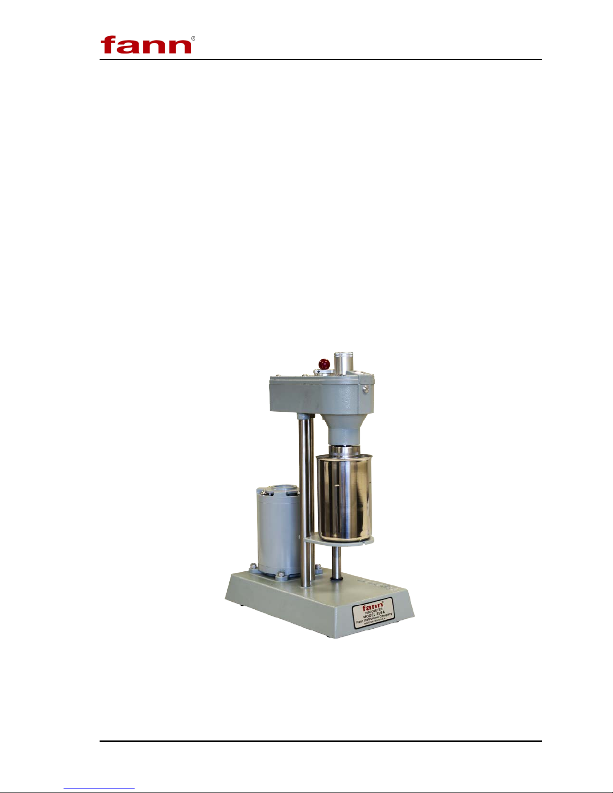
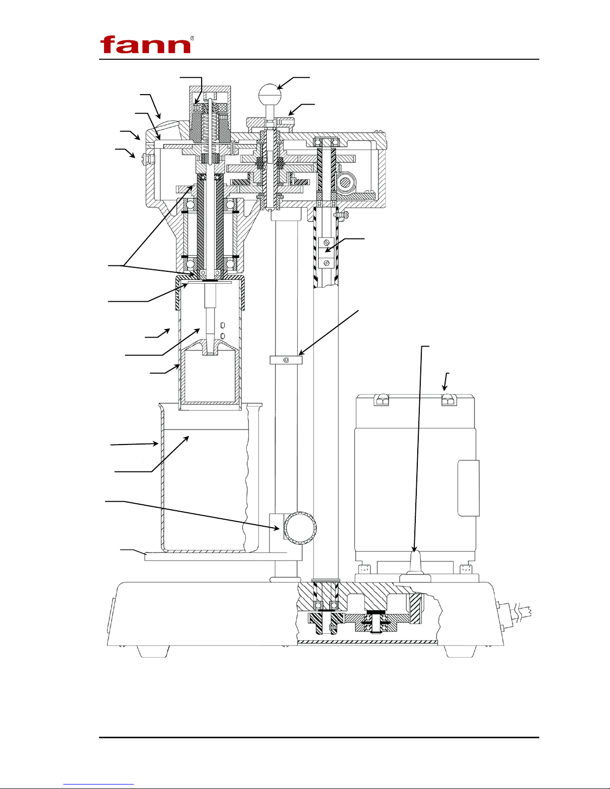
Figure 3-1 is a picture of the viscometer and Figure 3-2 is a detailed drawing that
names the individual parts.
208878 Revision N, February 2013 9
Figure 3-1 Model 35SA Viscometer
Model 35 Viscometer Instruction Manual
Switch
Lens
Gas Purge Nipple
Bob Shaft
Bob
Sample Fill Line
Locking Knob
Stage
Torsion Spring Assembly
Pointer
(optional)
Bearings
Splash Guard
Bob Shaft
Gear Shift Knob
Gel Knob
Dial
Coupling
Stop
Scribed Line
Motor Speed
Circulating Cup
(350 ml)
2 Speed Motor
208878 Revision N, February 2013 10
Figure 3-2 Model 35 Viscometer Schematic

Model 35 Viscometer Instruction Manual
Dimensions
(LxDxH)
39 x 15 x 27 cm
6.8 kg
39 x 15 x 27 cm
6.8 kg
20.3 x 40.6 x 48.3 cm
11.8 kg
20.3 x 40.6 x 48.3 cm
11.8 kg
No. of
Speeds
600, 300, 200, 180, 100,
90, 60, 30, 6, 3, 1.8, 0.9
600, 300, 200, 180, 100,
90, 60, 30, 6, 3, 1.8, 0.9
Table 3-1 Model 35 Viscometer Specifications
Model No. Part No. Electrical
35A 207198
35SA 207199
35A/SR-12 207200
35SA/SR-12
207201
115V, 60 Hz, 90W
115V, 50 Hz, 90W
115V, 60 Hz, 90W
115V, 50 Hz, 90W
Table 3-2 Model 35 Viscometer Sizes
Model No. Part No.
35A 207198
35SA 207199
15.2 x 6 x 10.5 in.
15.2 x 6 x 10.5 in.
15.2 x 6 x 10.5 in.
35A/SR-12 207200
6 600, 300, 200, 100, 6, 3
6 600, 300, 200, 100, 6, 3
12
12
39 x 15 x 27 cm
Speeds
Weight
15 lb
15 lb
15 lb
6.8 kg
35SA/SR-12 207201
35A w/ case 101671768
35SA w/ case 101671770
15.2 x 6 x 10.5 in.
39 x 15 x 27 cm
8 x 16 x 19 in.
8 x 16 x 19 in.
15 lb
6.8 kg
26 lb
26 lb
208878 Revision N, February 2013 11

Model 35 Viscometer Instruction Manual
Radius
(cm)
Length
(cm)
3.8
1.9
n/a
n/a
n/a
80% RH at 87.8oF (31oC) or les s
50% RH at 104oF (40oC)
Table 3-3 Rotor and Bob Dimensions
Unit
B1 1.7245
B2 1.2276
B3 0.86225
B4 0.86225
R1 1.8415
R2 1.7589
R3 2.5867
3.8
3.8
Cylinder Area (cm2) x Radius (cm)
71.005
35.981
17.751
8.876
n/a
n/a
n/a
Table 3-4 Rotor-Bob Specifications
ROTOR-BOB R1 B1 R2 B1 R3 B1 R1 B2 R1 B3 R1 B4
Rotor Radius, R0 (cm) 1.8415 1.7588 2.5866 1.8415 1.8415 1.8415
Bob Radius, Ri (cm) 1.7245 1.7245 1.7245 1.2276 0.8622 0.8622
Bob Height, L (cm) 3.8 3.8 3.8 3.8 3.8 1.9
Shear Gap in Annulus
(cm)
0.117 0.0343 0.8261 0.6139 0.9793 0.9793
Radii Ratio, Ri /R0 0.9365 0.9805 0.667 0.666 0.468 0.468
Maximum Use
Tempe rature (
Minimum Use
Tempe rature (
o
o
C)
C)
93 93 93 93 93 93
0 0 0 0 0 0
Table 3-5 Range of Environmental Conditions
Maximum Altitude
Temperature Range
6562 ft (2000 m)
o
F to 104oF (5oC to 40oC)
41
Maximum Relative Humidity (RH)
208878 Revision N, February 2013 12

Model 35 Viscometer Instruction Manual
4 Installation
The Model 35 should be placed in a position where there is easy access to the
power cord plug for disconnection.
Consideration should be given to the location where samples are prepared and
equipment is cleaned when the test is completed. There should be sufficient storage
area nearby for commonly used tools, as well as consumables.
208878 Revision N, February 2013 13

Model 35 Viscometer Instruction Manual
5 Operation
This section describes the operating instructions for the Model 35 series
viscometers. It also includes instructions for measuring gel strength and changing
rotors, bobs, and torsion springs.
To start the test, add 350 ml of pre-stirred sample to the stainless steel sample cup.
The sample cup has a line that marks 350 ml as shown in Figure 3-2.
A scribed line on the rotor indicates proper immersion depth. Refer to Figure 3-2.
Damage to the bob shaft bearings may occur if this immersion depth is exceeded. If
other sample holders are used, the space between the bottom of the rotor and the
bottom of the sample holder should be one-half inch (1.27cm) or greater.
The standard B1 Bob is hollow and should never be used to test
samples hotter than 200
o
F (93oC).
208878 Revision N, February 2013 14
 Loading...