


US-02
Table of contents
 Loading...
USER MANUAL
Dental unit
US-02.1 and US-02.3
Serial no: .............................................
Edition 5.01/ KOZN 374/2005
Żywiecka Fabryka Sprzętu Szpitalnego
FAMED S.A.

Appendixes: 2, 3,
User manual – dental unit US-02.1 and US-02.3
Page 2

User manual – dental unit US-02.1 and US-02.3
This product complies with type category IIa in accordance with the European
Medical Device Directive (MDD) 93/42/EEC, June 14th 1993, Appendix 9.
The Manufacturer declares that this product conforms to the basic requirements
of the MPG, Appendix 7, and documents conformity by marking this product
with “CE”.
Producer: FAMED S.A.
Ul. Fabryczna 1
34-300 Żywiec, Poland
Tel. +48 33 866 62 53
Infoline: (+48 33) 866 63 75 (24-hours a day)
Fax +48 33 861 46 78
expo.famed@famed.com.pl
www.famed-zywiec.com, www.famed.com.pl
Medical device was registered at Registration Office of Healing Products, Medical Products
and Bio fight Products in 18.09.2003 under no: PL/ DR 00 22 32
Page 3
User manual – dental unit US-02.1 and US-02.3
Dear Customer!
Please, read this user manual carefully because it contents the important
information and remarks of the manufacturer concerning proper product
installation, usage and conservation.
We congratulate you on good choice and wish satisfaction with
exploitation of our merchandise.
Żywiecka Fabryka Sprzętu Szpitalnego
FAMED S.A.
General notes
• The use, maintenance as well as servicing of this product performed in other
ways than those, which have been stated in this manual is forbidden and may
result in damages, which will encumber the user and which will not be a matter of
producer’s responsibility.
• When the operation and parameters of the product do not match the description in
item ‘Operation’ in this manual, the use of the product is not allowed and any
defects have to be reported to the producer or the supplier.
• Every repair of the product must be done by a factory or an authorized service (the
list of service companies enclosed in appendix 1) and recorded on the list of
repairs, which is supplied with the guarantee certificate. Disregarding this
requirement will cause the guarantee for the product to be invalid.
• Before starting any repairs the table must be disconnected from mains.
Notes concerned with safety
The sign shown below says: ‘Caution – pay special attention to the Operating Manual’.
A label showing this sign is placed on any parts or mechanisms, which may prove to
be harmful to the patient or the personnel if their operation does not comply with the
descriptions found in this Operating Manual.
• Do not connect the unit to mains in places where there is a danger of an explosion!
• Use of accessories, additional equipment, cables or spare parts other that those offered
and/ or advised by the producer may cause an increase of emission and/ or decrease of
bed resistance to all electromagnetic phenomena.
• Be careful when activating the pneumatic arm of the table of the unit. Moving elements
(moved by a pneumatic spring) may catch your fingers or hand. It is not allowed to put
hands or fingers on elements located close to moving elements of the structure. .
Page 4

User manual – dental unit US-02.1 and US-02.3
Notes concerning: start-up, operation and maintenance
• While blockade is on a table position cannot be changed since it can lead to blockade
damage.
• Use distilled water only! Otherwise handpieces may get damaged and it results in lost of
guarantee.
• Tool’s terminals will not work until the distilled water cycle is OFF
• The terminals can not be used without tools.
• Electrical micro-motor must not be lubricated.
Notes concerning cleaning and disinfecting
• The product must not be disinfected in disinfection chambers!
• No bleaching agents (containing active chlorine or oxygen), caustic or corrosive chemicals
are allowed!
• No agents destroying the structure of plastic (organic solvents) can be applied to the
plastic elements!
• Before disinfecting disconnect from power socket.
Disregarding the above requirements concerning cleaning and disinfecting shall result in
losing the guarantee for the product!
Page 5

User manual – dental unit US-02.1 and US-02.3
Content
1 PROPER USE AND APPLICATION ................................................................................................... 8
1.1 APPLICATION......................................................................................................................................... 8
1.2 GENERAL REQUIREMENTS.........................................................................................................................8
1.3 DUTIES OF THE USER ............................................................................................................................. 8
1.4 TECHNICAL DATA................................................................................................................................... 8
1.5 DESCRIPTION OF ELEMENTS AND FUNCTIONS.................................................................................................9
1.6 DESCRIPTION OF THE PRODUCT................................................................................................................ 10
1.7 SAFETY............................................................................................................................................. 10
1.8 CRITICAL PARAMETERS.......................................................................................................................... 10
1.9 ELECTROMAGNETIC COMPATIBILITY...........................................................................................................10
2 TRANSPORT AND FIRST USE ........................................................................................................ 11
2.1 TRANSPORT........................................................................................................................................ 11
2.2 UNPACKING AND FIRST USE.................................................................................................................... 12
2.3 START-UP.......................................................................................................................................... 15
3 USAGE AND HANDLING ................................................................................................................. 16
3.1 UNIT FUNCTIONING................................................................................................................................ 16
3.2 EQUIPMENT FUNCTIONING:......................................................................................................................16
3.3 EQUIPMENT......................................................................................................................................... 17
3.4 FOOT CONTROLLER............................................................................................................................... 18
3.5 TABLE...............................................................................................................................................18
3.6 CUSPIDOR BLOCK................................................................................................................................. 20
3.7 LAMP 20
3.8 INTERNAL DISTILLED WATER CYCLE...........................................................................................................20
3.9 SCALER AND MECTRON POLYMERISATION LAMP........................................................................................... 21
3.10 FUNCTIONAL PARAMETERS.................................................................................................................... 21
3.11 COLLISIONS...................................................................................................................................... 23
3.12 OPERATION WHEN PLUGGED TO THE POWER NETWORK.................................................................................23
4 ADDITIONAL MODULES .................................................................................................................. 23
4.1 STARTING SET WU-01.0...................................................................................................................... 23
4.2 CURING LAMP FARO WU-02.0...........................................................................................................23
4.3 SUCTION SYSTEM WU-03.0 (ADDITIONALLY SUCTION PUMP)..........................................................................24
4.4 ADDITIONAL SHELF FOR TOOLS WU-04.1.................................................................................................24
4.5 TRAY FOR CURING LAMP WU-05.0......................................................................................................... 24
4.6 MODULE OF 6-WAY SYRINGE WITH LIGHT WU-08.0....................................................................................24
4.7 NEGATOSCOPE WU-11.0..................................................................................................................... 24
4.8 LIGHT MODULE 1-HOSE WU-18.0..........................................................................................................24
4.9 LIGHT MODULE 2-HOSE WU-19.0..........................................................................................................24
4.10 ULTRASONIC SCALER MODULE WU-20.0................................................................................................24
4.11 ELECTRIC MICRIMOTOR MODULE WU-21.0............................................................................................ 24
4.12 WATER HEATER MODULE WU-22.0...................................................................................................... 25
4.13 ADDITIONAL HOSE MODULE WU-23.0 AND WS-23.1...............................................................................25
4.14 ARM WITH PNEUMATIC BLOCK WU-38.1............................................................................................... 25
5 CONTROL CRITERIA OF PRODUCT CORRECT FUNCTIONING .................................................. 25
6 SERVICE ........................................................................................................................................... 25
6.1 STORING............................................................................................................................................ 25
6.2 WASHING, DISINFECTING AND MAINTENANCE OF THE SURFACE OF THE UNIT .......................................................25
6.3 WASHING, DISINFECTING AND MAINTENANCE OF DENTAL TOOLS.......................................................................26
6.5 BULB REPLACEMENT IN THE ILLUMINATING LAMP......................................................................................... 27
6.6 CONSERVATION LIST – DONE ONLY BY A SERVICE WORKER:...........................................................................29
6.7 DAMAGES AND DEFECTS LOCALISATION AND IDENTIFICATION...........................................................................29
6.8 REPAIRS AND MAINTENANCE ACTIVITIES..................................................................................................... 29
6.9 LIST OF THE MAINTENANCE ACTIVITIES...................................................................................................... 30
6.10 DAMAGES AND DEFECTS LOCALISATION AND IDENTIFICATION........................................................................30
Page 6

User manual – dental unit US-02.1 and US-02.3
7 CHARACTERISTICS OF ELECTROMAGNETIC ENVIRONMENT ................................................. 31
8 DENTAL UNIT IDENTIFICATION ..................................................................................................... 33
6.2 NAMEPLATE........................................................................................................................................33
6.3 LABELS............................................................................................................................................. 34
7 TERMINAL CONSERVATION – GUIDELINES ................................................................................. 34
Page 7

User manual – dental unit US-02.1 and US-02.3
1 Proper use and application
1.1 Application
Dental unit US-02.1 and US-02.3 is destined for dental check-ups and procedures on adults, children
and disabled on wheelchairs.
1.2 General requirements
The product is intended to be used indoors. Required climatic conditions: temperature from +10 to
+40ºC, acceptable change of surrounding temperature during 8 hours should not exceed 20°C,
relative humidity of the air should range from 30 to 80%, atmospheric pressure from 700 to 1060 hPa.
The product should be used, maintained and serviced according to the indications of this manual.
Using, maintaining and servicing the product in other way than indicated in this
manual is not permitted and may lead to damages for which the user is to blame
and for which the producer is not responsible.
Caution!
Installation of other accessories than those offered by the producer for the
product is allowed only on the basis of a written acceptance of the producer.
The Unit can not be used as hanger, stand, drill or vacuum.
1.3 Duties of the user
User: any individual or corporate body who uses the product as its owner, lessee, pledge or who has
a different right to the product as well as an entity who uses the product on its own or on whose behalf
it is used.
The user must ensure that the product shall be used exclusively in conformity with its destination and
that it is used in appropriate conditions and in consistence with this manual. The user is also obliged to
take all necessary precautions in order to prevent all life and health haza rds concerning the user,
patients and any third party. Only authorised persons who underwent special training and are
acquainted with this manual may operate the product. The user must also ensure that all persons who
operate the product have read, understood and apply instructions contained in this manual.
1.4 Technical data
- Power supply 230V~ 50/60Hz
- Value of a fuse on voltage 230V T3, 15 A
- Power consumption (maximal) 400 W
- Input air pressure 0,45 MPa
- Filtration net on air filter on inlet 5 µm
- Input water pressure 0,25 MPa
Filtration net on water filter on inlet 80 µm
- Water pressure in distilled water circulation 0.2 MPa
- Temperature of water for cup 38°C ±5°C
- Maximum light illumination 25000 lux (for light EDI)
Maximum light illumination 21500 lux (for light CELIA)
- Saliva ejector efficiency 0,7 l/min by the water pressure 0.2MPa
- weight 65 kg
Class of protection before electric paralysis I
Type of the part application B
- Protection degree IPX2
- Usage period 10 lat
- Maximal additional load of doctor’s table 3 kg
- Maximal additional load of cuspidor block 1 kg
For the special cliente request it’s possiblr to produce the product with change parameters, not
lowering it’s safety.
Page 8
User manual – dental unit US-02.1 and US-02.3
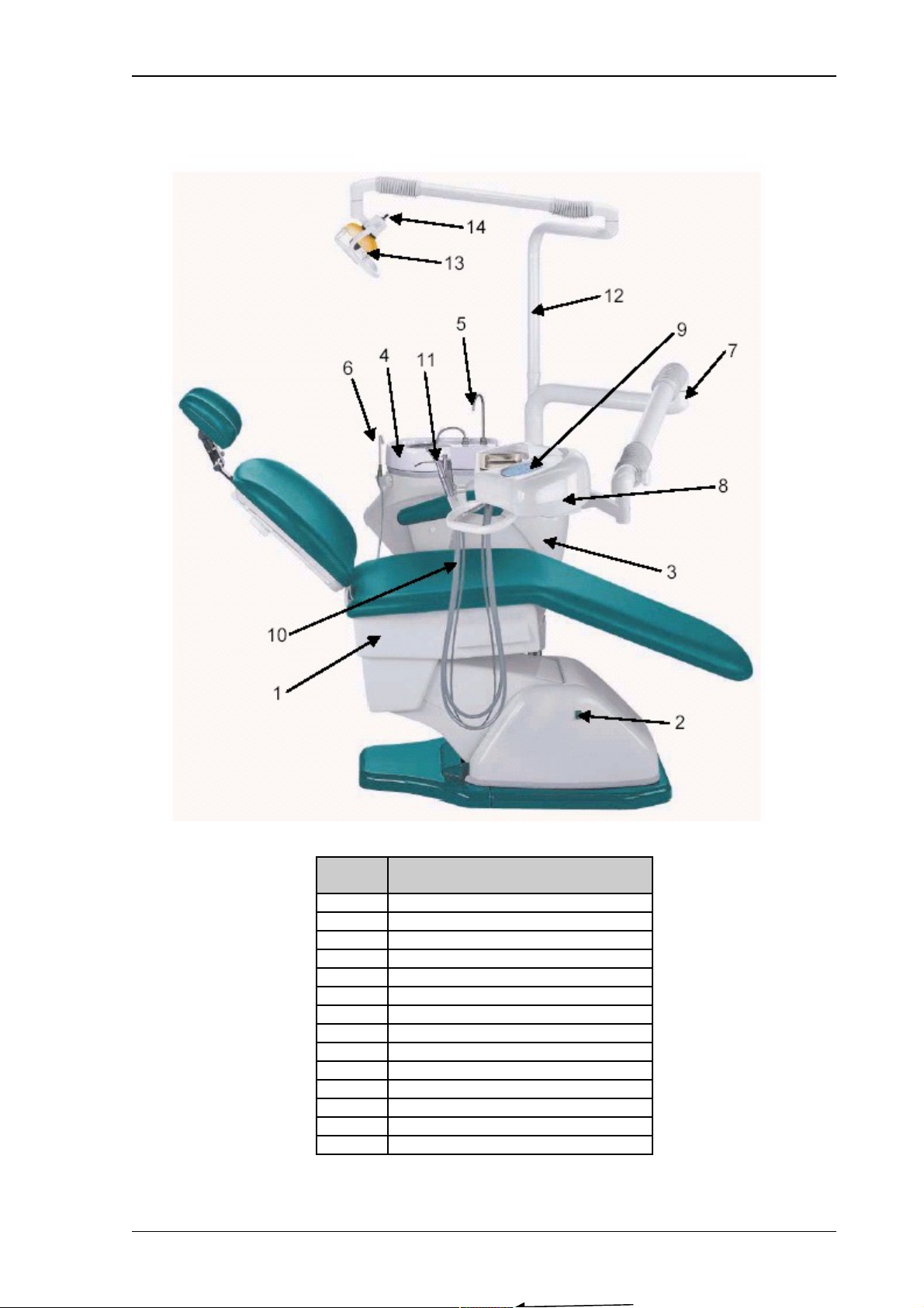
1.5 Description of elements and functions
FIG. 1
Pos. in
fig. 1
1 Dental chair
2 On / off switch
3 Cuspidor block
4 Cuspidor weight
5 Cup filling point
6 Saliva ejector
7 Table’s pantograph arm
8 Doctor’s table
9 Steering panel
10 Upper installed hoses
11 Instruments
12 Lamp’s pantograph arm
13 Lamp
14 On / off switch of lamp
Description
Page 9
User manual – dental unit US-02.1 and US-02.3
1.6 Description of the product
The dental unit is installed on a dental chair. It can also operate independently (without the chair). A
change of the height of chair causes a change of position of the unit thanks to which it is not
necessary to adjust position of the unit after each change of height of the chair.
The unit may be provided with a doctor’s table fixed on the arm which allows to position the table
precisely. A set of tools (according to individual requirements of a client) and a panel which allows to
control unit and armchair functions are located on the table. The unit may be provided with an
assistant table. The unit may be provided with a shadowless lamp.
Because of universality and module structure and a wide offer of accessories the unit can be set in
various confgurations according to doctor’s specifications.
The producer reserves the right to introduce in the product structural modifications resulting
from technical progress which are not covered in this user manual.
The producer reserve that all parameters and accesories can be modyfied or change,
especially construction, technology and materials, not lowering accepted parameter
technically-user and safeties of products.
1.7 Safety
The structure of the product assures its safe operation and use on condition that the rules
comprised in this manual are followed.
Caution: The sign shown below says: “Caution – pay special attention to the User Manual”.
A label showing this sign is placed on any parts or mechanisms, which may prove
to be harmful to the patient or the personnel if their maintenance will not comply
with the descriptions found in this Operating Manual.
When operating the product the user has to pay attention to the elements and
mechanisms marked as shown above.
1.8 Critical parameters
Maximal input air pressure - 0,8 Mpa
Maximal input water pressure - 0,6 Mpa
1.9 Electromagnetic compatibility
Medical device: dental unit US-02.1 and US-02.3 is an electric appliance. Electric appliances are a
source of electromagnetic radiation and themselves are under its influence. Therefore, use of an
medical devices requires some safety precautions connected with electromagnetic compatibility.
In tables: item 7 Characteristics of electromagnetic environment – electromagnetic
environment in which medical device dental unit US-02.1 and US-02.3 should be used is
described. Recommendations and warnings which should be followed by the users were also
presented.
Page 10
Caution!
Pd 2,1
=
Pd 2,1
=
Pd 3,2
=
User manual – dental unit US-02.1 and US-02.3
Use of different accessories, additional equipment, cables, spare parts than those
offered and/ or recommended by the producer may cause an increase of emission
and/ or decrease of bed’s resistance to all electromagnetic phenomena.
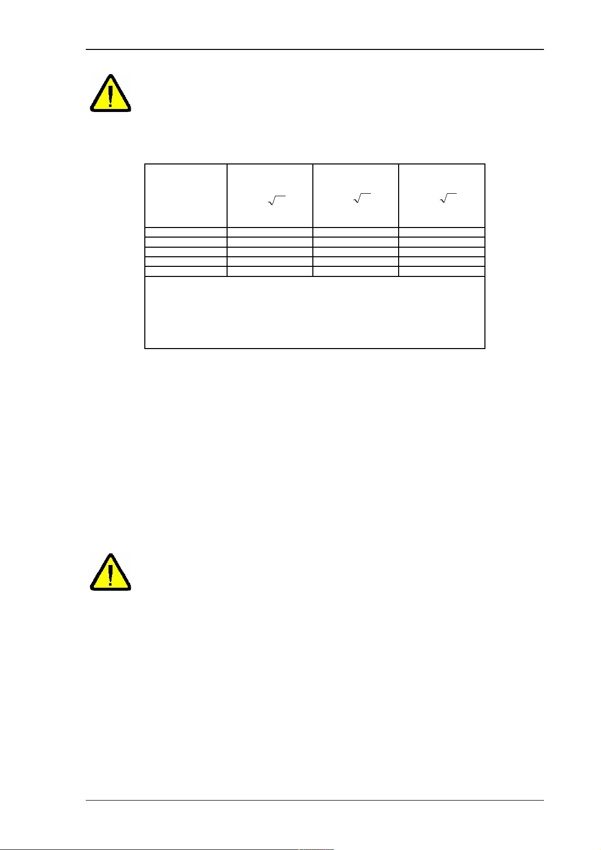
Recommended distances between portable radio-transmitters and product
Rated output
power of the
transmitter in watts
[W]
0.01 0.1 0.1 0.2
0.1 0.4 0.4 0.7
1 1.2 1.2 2.3
10 4 4 7
100 12 12 23
For transmitters whose maximum output power is not detailed above, the separation distance
should be calculated on the basis of the formulas given above. P is the power in watts (W) as
declared by the producer of transmitter
ATTENTION
The above recommendations may be inadequate in some situations. Propagation of
electromagnetic waves can be absorbed or reflected from buildings, structures and people.
150 kHz to 80 MHz
distance in meters
150 kHz to 800 MHz
distance in meters
800 MHz to 2.5 GHz
distance in meters
2 Transport and first use
2.1 Transport
There is a possibility to transport the product by any covered transport means. While transporting, it is
necessary to immobilize the truck and protect it against moisture.
The transport conditions are as follows:
- temperature: from –10OC to 60OC (for the products including electronic parts),
from –20OC to 60OC (the other products),
- relative humidity: from 20% to 80%.
In case if unit is transported in temperature below zero degrees centigrade, all
tanks and conduits containing water should be emptied. Water left in unit
hydraulic systems during transport in freezing temperature may result in unit
damage.
Caution!
While product transporting, storage and unpacking, the temperature gradient should be less than 10OC
per hour. It is strongly recommended to unpack the product after reaching room temperature.
In case of products which comprise electronic systems when the difference between transport
temperature and room temperature in which the product is located is considerable, the product should
be left there for 12 hours. Only after that period it can be started.
Laminar storage is permissible in accordance with the packaging marking. In the absence of the
marking, storied storage is prohibited.
In case of the specific transport conditions (particularly: low temperature transport), it is necessary to
negotiate the way of transport and product packaging with the product manufacturer in order to ensure
safe transport.
Page 11
User manual – dental unit US-02.1 and US-02.3
2.2 Unpacking and first use
2.2.1 Unpacking
The set is delivered to the customer disassembled. It is packed in wooden or cartoon boxes.
Unpacking must be done inside a building as to protect the unit form damage. In order to make the
unit ready to work the following must be done:
• set the tray,
• remove strips,
• remove cartoon lid,
• remove cushioning material,
Package waste is recyclable and should be segregated before removed to a
disposal site. Returnable packaging should be returned to the producer of the
medical product.
Caution!
• carefully take the unit from wooden pallet and bring it into destined place
2.2.2 Installation of cuspidor block on the chair .
Place the cuspidor on the chair arm. Protect it against turning using screws in the shank. Cuspidor’s
axis of rotation must be vertical.
A trained service worker must do the installation.
After each displacement of the chair level the cuspidor block.
Caution!
2.2.3 Lamp installation
Remove cuspidor’s cover. Lead the power supply cable to the lamp holder and place the lamp in it.
Connect the power supply cable to electronic circuit according to proper markers.
A trained service worker must do the installation.
Caution!
2.2.4 Table installation.
Remove the table cover. Fix the table to arm with screws from the side of table metal plate and holder.
Lead wires through the hole in the table metal plate and connect them to the electronic circuits
according to proper markers. Connect water and sir pipes according to proper markers. Install the
table cover.
A trained service worker must do the installation.
Caution!
2.2.5 Installing the unit
The floor where that unit is installed must be stiff (otherwise there can be a problem with levelling of
the unit).
All connections are placed inside of dental chair’s base. There are connections for power supply
water supply system, compressed air system and sewerage system.
Page 12
Loading...