

Page 1
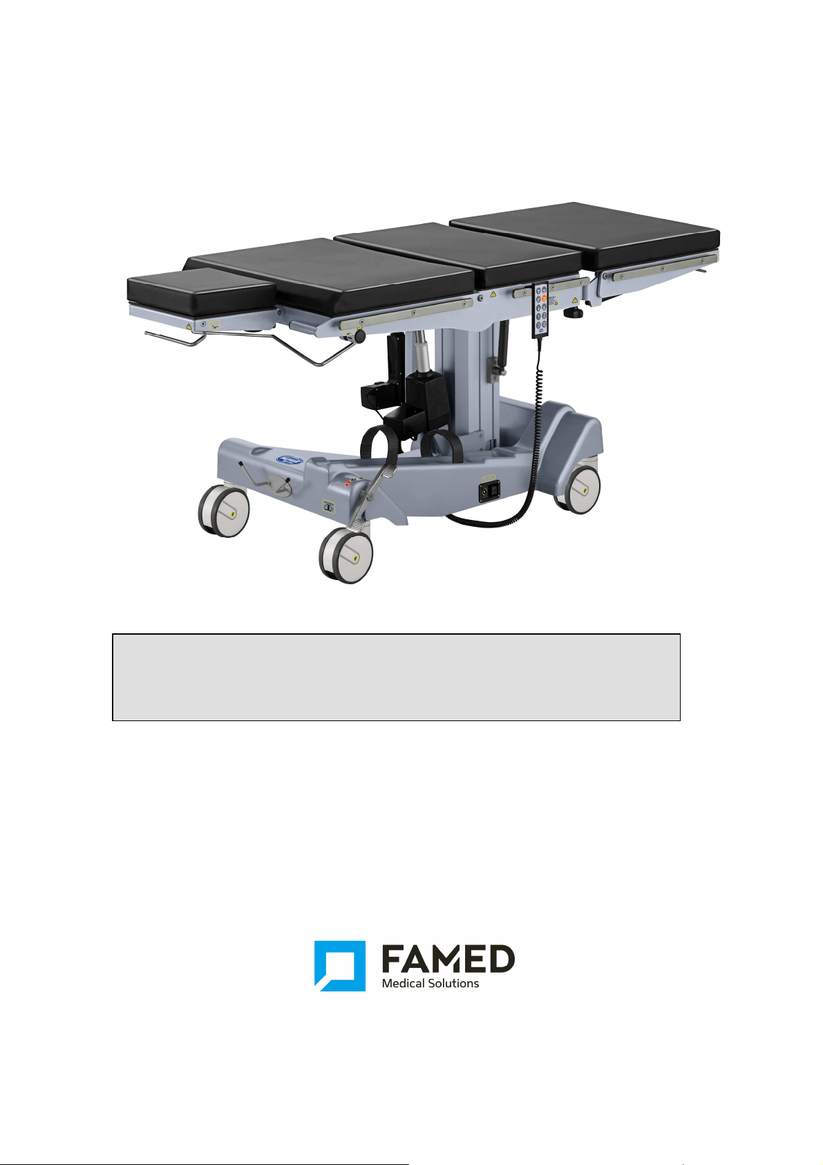
USER MANUAL
Operating table
SU-14
Factory number: ........................................
…. ....................................
…. ....................................
Edition 10.00
Issuance date:
March 2017
FAMED ŻYWIEC Spółka z o.o.
Appendixes: 2, 3, List of Spare Parts.
Page 2
User manual for Operating table SU-14
As provided in the Directive on Medical Equipment 93/42/EEC of 14 June 1993
this is first risk class product.
The producer declares that the product meets basic requirements of the
directive contained in Appendix 1.
The compliance procedure was carried out in accordance with appendix VII of
the directive.
Manufacturer:
Famed Żywiec Sp. z o.o.
Fabryczna 1
34-300 Żywiec
POLAND
Phone numbers:
Info line (+48 33) 866 63 75 (24-hours a day)
Head office (+48 33) 866 62 00
Marketing Department (+48 33) 866 63 00 ...02
Export Department (+48 33) 866 62 50 ... 52
Service (+48 33) 866 63 25
Fax : (+48 33) 475 58 90
Page
2
Page 3

User manual for Operating table SU-14
Dear Clients,
Congratulations on choosing the right product, we wish you would find a
lot of satisfaction while operating it.
Please read this manual very carefully as it includes all the vital
information and notes from the producer concerning proper installation
and maintenance of the product as well as its service.
FAMED ŻYWIEC Spółka z o.o.
General notes
• The use, maintenance as well as servicing of this product performed in other ways
than those, which have been stated in this manual is forbidden and may result in
damages, which will encumber the user and which will not be a matter of producer’s
responsibility.
• When the operation and parameters of the product do not match the description in
item ‘Operation’ in this manual, the use of the product is not allowed and any
defects have to be reported to the producer or the supplier.
• Every repair of the product must be done by a factory or an authorized service and
recorded on the list of repairs, which is supplied with the guarantee certificate.
Disregarding this requirement will cause the guarantee for the product to be invalid.
• Before starting any repairs the table must be disconnected from mains.
• Operation table has been designed for a patient of 200kg of weight.
Notes concerned with safety
The sign shown below says: : "Warning! - Follow the instructions for safe use ".
A label showing this sign is placed on any parts or mechanisms, which may prove
to be harmful to the patient or the personnel if their operation does not comply
with the descriptions found in this Operating Manual.
• Do not move the table when it is connected to the main power supply. Before
moving the table, remove the power cord from the mains.
• The table should not be in the place which obstructs its disconnection from the
mains!
• Throughout surgical procedures table wheels should be blocked.
• Do not lay patient's torso on the footrest segment.
• During carrying out angle adjustments or lowering operation table's height,
anyobstacles must be removed from below the table's surface.
• During changing the position of the table top segment should not extend
belowor between elements of tabletop.
• Do not shift operation table's position with installed orthopedic
attachment,proctology attachment, installed gynecological segment or installed
shoulder operation attachment due to danger of capsizing the table.
Page
3
Page 4

User manual for Operating table SU-14
• Lock operation table in given position before transporting a patient.
• When using the table close to medical equipment working on high frequencies
and defibrillators one should closely follow operating instruction for that
equipment. Improper operation may become a source of dangerous accidents.
There is a danger of serious burning of the patient through the contact with
metal parts of the table or its equipment.
• Throughout surgical procedures the table must be connected to the installation
of potential equalization in the operations room.
• You must make sure, that accessories are properly fixed to the tabletop.
• When changing operation table's position you must avoid any collisions
between the table and accessories.
• Not original accessories may be applied only after consulting with Famed
Żywiec company about their use.
• Operation table's electrical conductivity must be checked once a year. The
check should be carried out by trained service personnel.
• Avoid endangering patient's respiratory system, neural pathways and
circulatory system by ensuring the patient is in proper position and by
observing his/her condition.
• When performing longitudinal (Trendelenburg or reverse Trendelenburg) and
lateral tilt, patient should be secured against uncontrolled sliding down from the
operating table. Use shoulder supports, supporting rollers, side supports, belts
and grips as securing elements.
Notes concerning: start-up, operation and use
• The table, during use, should not be in the place which obstructs its
disconnection from the mains!
• When performing longitudinal (Trendelenburg or reverse Trendelenburg),
backrest should be in zero position or above the horizontal level.
• When anti-trendelenburg function is performed, footrests may collide with the
basis.
• When performing Trendelenburg function or functions downward movement
may take place collision with the base of the backrest ( backrest tilted down).
• Adjusting angle position of a back rest requires manual operation.
• The table should be moved by 2 people at least.
• Do not move table with workload (patient).
• The table should be moved in minimal height.
• The floor under the table should be free from any obstacles.
• When rolling the table avoid collisions.
• Do not roll the table over electric cables.
• The table has to be connected to mains in consistence with its name plate.
• Do not use the cable when it is damaged or its insulation is worn out.
• Do not connect the table to mains in places where there is a danger of an
explosion.
• Do not store a table with flat batteries (a red diode is illuminated on a controlling
device during any movement).
Page
4
Page 5

User manual for Operating table SU-14
• When batteries need to be exchanged, do always exchange a set of two
batteries, exchange of a single battery causes limitation to operating time of a
table and quick wear of a new battery.
• Hand support should be fixed on table strip with a multi-position grip which
makes angular movement of the support possible.
• If it is necessary to replace oil or a battery (dangerous waste), one should follow
existing environmental protection regulations.
• Hand controller is the obligatory accessories for surgical tables.
• Hand controller must be within reach of the medical staff.
Notes concerning disinfecting
• The product must not be disinfected in disinfecting chambers!
• No bleaching agents (containing active chlorine or oxygen), caustic or corrosive
chemicals are allowed!
• No agents destroying the structure of plastic (organic solvents) can be applied
to the plastic elements!
• No disinfecting agents containing alcohol are allowed for cleaning of
polyurethane elements (mattresses).
• Before disinfecting disconnect the table from mains pulling out the cable!
Disregarding the above requirements concerning cleaning and disinfecting shall
result in losing the guarantee for the product!
Page
5
Page 6

User manual for Operating table SU-14
Contents
1 PROPER USE AND APPLICATION ......................................................................................................... 7
1.1 USE ......................................................................................................................................................... 7
1.2 GENERAL REQUIREMENTS ............................................................................................................... 7
1.3 DUTIES OF THE USER .......................................................................................................................... 7
1.4 DESCRIPTION OF PRODUCT ............................................................................................................... 7
1.5 COMPONENTS AND FUNCTIONS DESCRIPTION .......................................................................... 8
1.6 TECHNICAL DATA ............................................................................................................................. 9
1.7 USE PARAMETER.……………………………………………………………………………………. 10
1.8 SAFETY .............................................................................................................................................. 11
1.9 CRITICAL PARAMETERS…………………………………………………………………………....11
1.10 ELEKTROMAGNETIC COMPATIBILITY…………………………………………………………...11
2 TRANSPORT AND FIRST USE ................................................................................................................ 13
2.1 T
RANSPORT
.......................................................................................................................................... 13
2.2 UNPACKING AND FIRST USE …………………………………………………………………… ..13
3 OPERATION AND USE ............................................................................................................................ 15
3.1 CONTROLLING ELEMENTS ............................................................................................................. 15
3.2 RAISIING AND LEVELING OF TABLE TOP .................................................................................. 16
3.3 TABLE TOP LONGITUDINAL INCLINATION ............................................................................... 16
3.4 TABLE TOP SIDE INCLINATION .................................................................................................... 16
3.5 MEMORY OF TABLE TOP POSITION ( ZERO POSITION) .............................................................. 16
3.6 CHANGE OF THE ANGULAR POSITION OF THE BACKRES SEGMENT .................................. 16
3.7 CHANGE OF ANGULAR POSITION OF THE FOOTRESTS ................................................................ 17
3.8
INSERT AND TAKE OUT OF FOOTREST
........................................................................................................ 17
3.9 INSERTING AND REMOVING FOOTREST………………………………………………………….18
3.10 INSTALLATION AND REMOVAL OF THE HEADREST .................................................................... 18
3.11 INSTALLATION AND DISASSEMBLY OF MATRESSES ............................................................. 18
3.12 T ABLE MOBILITY ............................................................................................................................ 18
3.13 ANTISTATIC PROPERTIES ................................................................................................................. 19
3.14 POTENTIAL EQUALIZING CLAMPS ................................................................................................ 19
3.15 COLISION ............................................................................................................................................ 19
3.16 BATTERY CHARGINGS ................................................................................................................... 19
4 INSTALLATION AND OPERATION OF ACCESSORIES ................................................................. 20
5 CRITERIA FOR ASSESSING THE ACCURACY OF OPERATION...................................................21
6.1 STORING ............................................................................................................................................. 22
6.2 CLEANNING AND DISINFECTION .................................................................................................. 22
6.3 DAMAGES AND DEFECTS .............................................................................................................. 22
6.4 REPAIRS AND CONSERVATION .................................................................................................... 22
6.5 CONTROL OF TECHNICAL INSPECTION ....................................................................................... 23
6.6 LOCATION OF DEFECTS AND THEIR REMOVAL ......................................................................... 24
6.7 PRODUCT LIQUIDATION ................................................................................................................. 24
7 CHARAKTERISTIC OF ELECTROMAGNETIC ENVIRONMENT .................................................. 25
8 TABLE IDENTIFICATION ...................................................................................................................... 27
8.1 NAME PLATE ..................................................................................................................................... 27
8.2
LABELS ................................................................................................................................................ 28
Page
6
Page 7
User manual for Operating table SU-14
Using, maintaining and servicing the product in other way than indicated in this
1. Proper use and application
1.1 Use
Operating table SU-14 is designed for supporting the patient during carrying out treatments and
operations. The table with the proper accessories can be used for treatments and operations in the
range of general surgery, vascular surgery, cardio surgery, neurosurgery, urology, proctology,
gynecology, laryngological, ophthalmology, endoscopies, laparoscopy, traumatic, oncology, dental,
plastic surgery and others. Table top segments are X-ray permeable.
1.2 General requirements
The product is intended to be used indoors. Required climatic conditions: temperature from +10 to
+45ºC, acceptable change of surrounding temperature during 8 hours should not exceed 20°C,
relative humidity of the air should range from 30 to 80%, atmospheric pressure from 700 to 1060 hPa.
The product should be used, maintained and serviced according to the instructions contained in this
manual.
manual is not permitted and may lead to damages for which the user is to blame
and for which the producer is not responsible.
Caution!
1.3 Duties of the user
User: any individual or corporate body who uses the product as its owner, lessee, pledge or who has
a different right to the product as well as an entity who uses the product on its own or on whose behalf
it is used.
The user must ensure that the product shall be used exclusively in conformity with its destination and
that it is used in appropriate conditions and in consistence with this manual. The user is also obliged to
take all necessary precautions in order to prevent all life and health hazards concerning the user,
patients and any third party. Only authorised persons who underwent special training and are
acquainted with this manual may operate the product. The user must also ensure that all persons who
operate the product have read, understood and apply instructions contained in this manual.
Installation of other accessories than those offered by the producer for the
product is allowed only on the basis of a written acceptance of the producer.
1.4 Description of product
The operating table consist of table base and table top that are permanently connection.
In standard version the table has a mobile base , equipped with central blockade, which is released
with a foot lever.
The table-top consists of segments, which number and configuration has constants number and
configuration (according to a customer special order this number will be change). Segments of table
top are X-ray permeable. The table top is provided with polyurethane mattresses. On both sides of the
top there are side strips which allow installing accessories.
Change of the angle of table top segments as well as movement of the column are adjusted by
mechanic electro-mechanics systems. In standard version the electric and electromagnetic
movements of table can be controlled by wire-connected controller.
Thanks to the wide range of offered accessories the table can be used for different types of operations
according to client wish. List of accessories you can find in Paragraph 4 - Installation and operation of
accessories.
The main power outlet is connected to the table by the power cord. In order to disconnect, the user
must unplug the power cord from the main power outlet.
The producer reserves the right to introduce in the product structural modifications resulting
from technical progress which are not covered in this user manual.
The producer reserves that all parameters and accessories can be modified or change,
especially construction, technology and materials, not lowering accepted parameter
technically - user and safeties of products.
Page
7
Page 8
User manual for Operating table SU-14
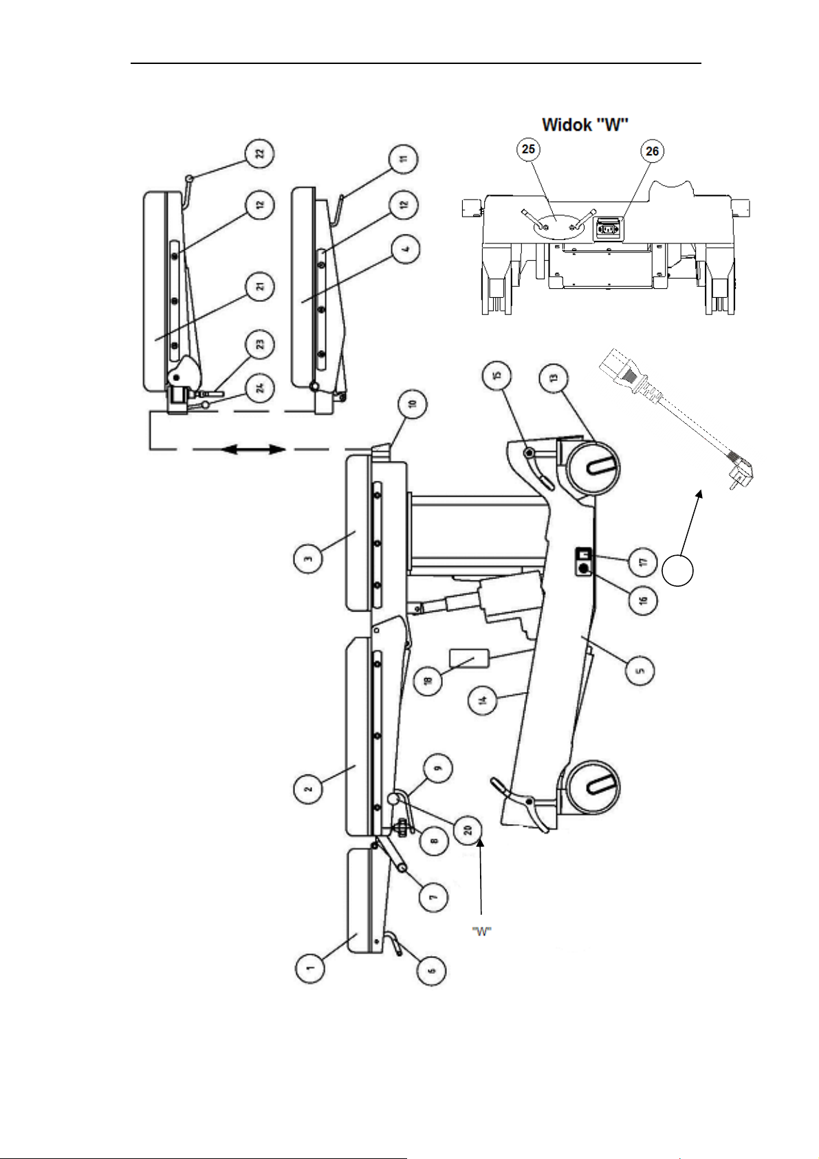
1.5 Components and Functions description
27
Fig.1 Operating table SU-14
Page
8
Page 9

User manual for Operating table SU-14
17 central switch(off) table supplying
18 wire-connected controller
26 Power socket
Nr on fig.1
1 headrest
2 backrest segment
3 seat segment
4 footrest segment
5 basis
6 headrest angle change lever
7 table top handle
8 blocking control of headrest
9 backrest position angle change lever
10 footrest blockade control
11 footrest angle change lever
12 side stripes
13 wheels
14 bottle assembling belts (option)
15 wheels central blockade lever
16 Potential equalizing clamps
19 basket for accessories (option)
20 Blockades of lowering of backrest lever
21 Footrest segment two-piece (option)
22 Footrest angle change lever
23 Footrest abduction bolt
24 Footrest blockade lever
25 Alimentation cable holder
Description
27 Power cable
1.6 Technical data
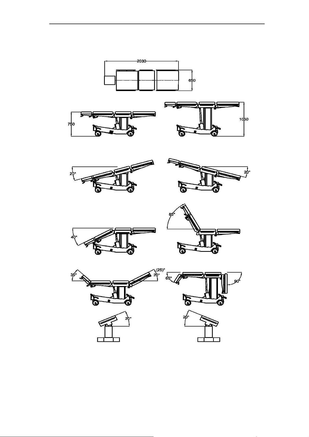
• total table top length 2030mm ± 15 mm
• mattress width 605 mm ± 5 mm
• total width of the table top ( with terminal ) 650 mm ± 5 mm
• min table top height from floor (the table stands on wheels) 750 mm ± 15 mm
• max table top height from floor (the table stands on wheels) 1050mm ± 15 mm
• lifting angle of seat segment 85°
• lowering angle of seat segment 40°
• lifting angle of leg segment 20°(25)*
• lowering angle of foot-support 90°
• Footrests widening angle 180° (for two-piece footrests)
• angle of lateral tilt ± 20°
• head section lifting angle up 35°
• head section lifting angle down 65°
• Trendelenburg 20°
• Anti-Trendelenburg 20°
• table mass 160 kg
• maximum workload 200 kg
• power supply 24V –
• work time without external alimentation ok. 10 operations
• power supply from main charge the batterie ~230 V 50/60 Hz
• integrated driver with charger and batteries
• Power consumption 240VA
• Class of protection before electric paralysis I
• Type of the part application B
• Degree of protection before influence of environment IP-X4
• type of work missing 2 / 18 min
• usage time 10 years
For special requests of the client it is possible to make a product of changed technical
parameters, not lowering its safety.
Page
9
Page 10
User manual for Operating table SU-14
1.7 Use parameters
The drawing below presents the main use parameter
fig.2
Page
10
Page 11
User manual for Operating table SU-14
1.8 Safety
The structure of the table assures its safe operation and use if the rules provided in this manual are
followed.
The sign shown below says: "Warning! - Follow the instructions for safe use ".
A label showing this sign is placed on any parts or mechanisms, which may prove to
be harmful to the patient or the personnel if their operation does not comply with the
descriptions found in this Operating Manual.
When operating the table one should pay attention to elements and mechanisms with
this label.
• Throughout surgical procedures table wheels should be blocked.
• When using the table close to medical equipment working on high frequencies and
defibrillators one should closely follow operating instruction for that equipment.
Improper operation may become a source of dangerous accidents. There is a danger of
serious burning of the patient through the contact with metal parts of the table or its
equipment.
• Throughout surgical procedures the table must be connected to the installation of
potential equalization in the operations room.
• When performing longitudinal (Trendelenburg or reverse Trendelenburg) and lateral
tilting, patient should be secured against uncontrolled sliding down from the operating
table. Use shoulder supports, supporting rollers, side supports, belts and grips as
securing elements.
• Pay special attention when performing sliding down from the operating table
,Trandelenburg or anti- Trandelenburg while the backrest or fotrest are inclination to
the bottom.
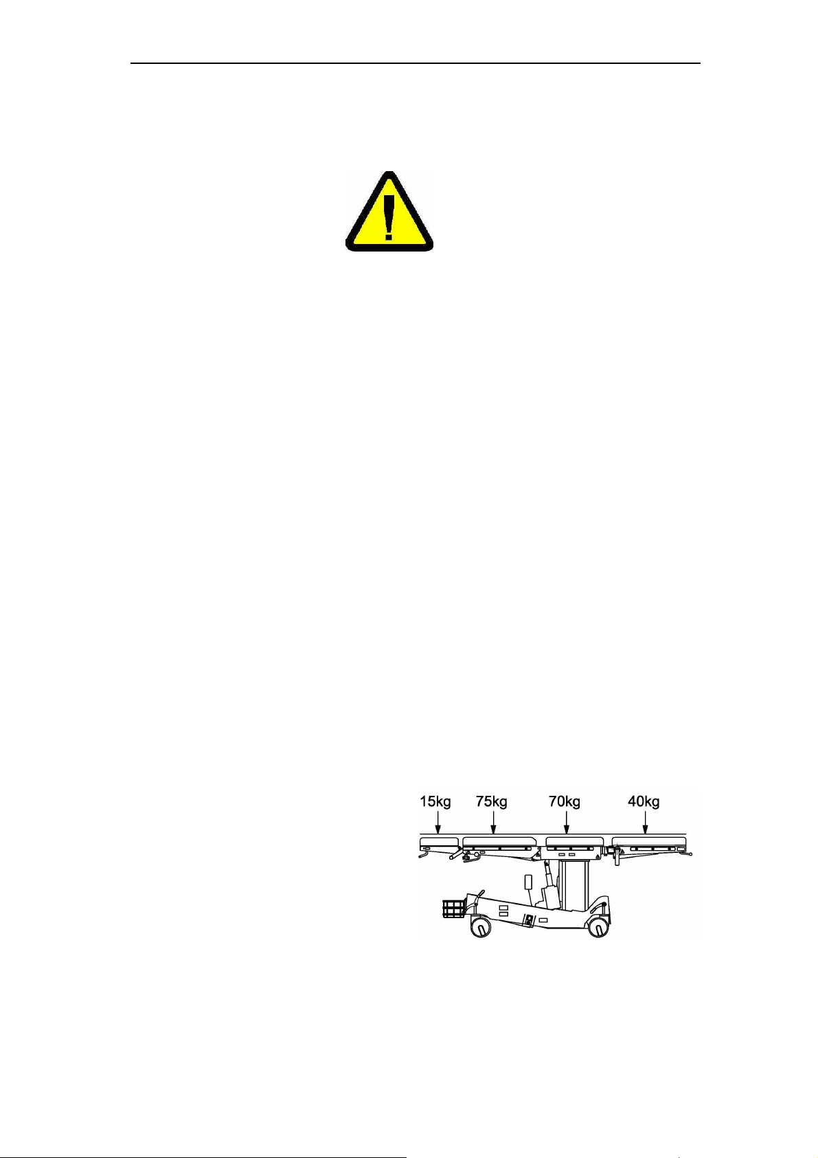
1.9 Critical parameters
Maximum work load - 200 kg
Maximum authorized segment load:
- head rest 15 kg
- backrest segment 75 kg
- seat segment 70 kg
- footrest (single) 20 kg
- footrests (simultaneusly loaded) 40 kg
Fig. 3
1.10 Electromagnetic compatibility
Medical device the operating table SU-14 is an electric appliance. Electric appliances are a source of
electromagnetic radiation and themselves are under its influence Therefore, use of an electric
appliance requires some safety precautions connected with electromagnetic compatibility.
Page
11
Page 12
User manual for Operating table SU-14
In tables: item 7 Characteristics of electromagnetic environment – electromagnetic environment in
which medical device the table SU-14 should be used. Recommendations and warnings which should
be followed by the users were also presented.
Use of different accessories, additional equipment, cables, spare parts than those
offered and/ or recommended by the producer may cause an increase of emission
and/ or decrease of bed’s resistance to all electromagnetic phenomena.
Caution!
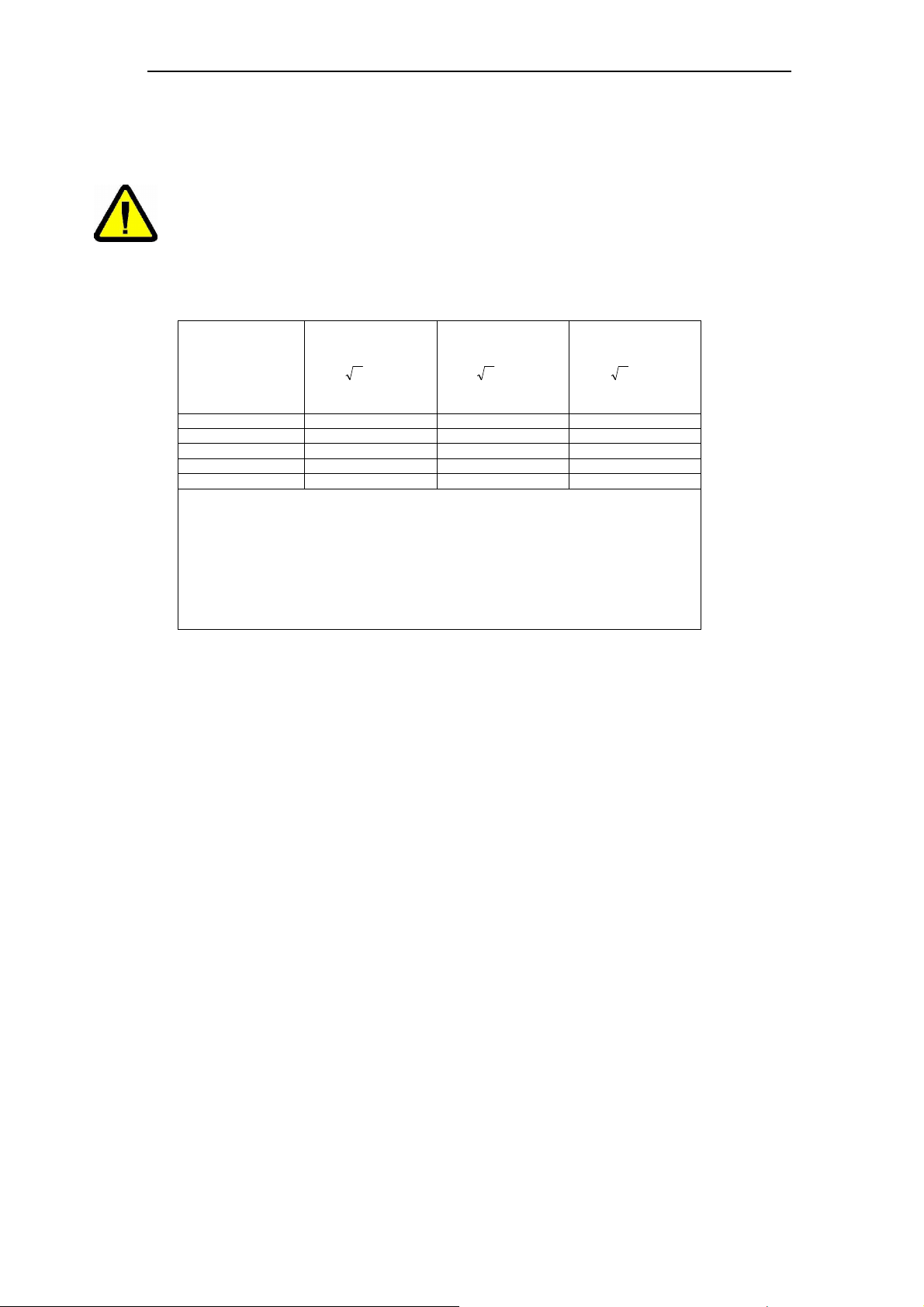
Recommended distances between portable radio-transmitters and the product
Rated maximum
output power of
transmitter
W
0.01 0.1 0.1 0.2
0.1 0.4 0.4 0.7
1 1.2 1.2 2.3
10 4 4 7
100 12 12 23
For transmitters, the maximum output power of which is not specified above, the separation
distance should be calculated according to the formulas provided. P is a power in watts (W)
according to the declaration of the transmitter manufacturer.
NOTE The above guidelines may not be applicable to all cases. Propagated electromagnetic
waves are absorbed and reflected from buildings, objects and people.
150 kHz to 80 MHz
distance in meters
Pd 2,1=
150 kHz to 800 MHz
Pd 2,1=
distance in meters
800 MHz to 2.5 GHz
Pd 3,2=
distance in meters
Page
12
Page 13
User manual for Operating table SU-14
2. Transport and first use
2.1 Transport
There is a possibility to transport the product by any covered transport means.
The transport conditions are as follows:
- temperature: from –10OC to 60OC,
- relative humidity: from 25% to 75%.
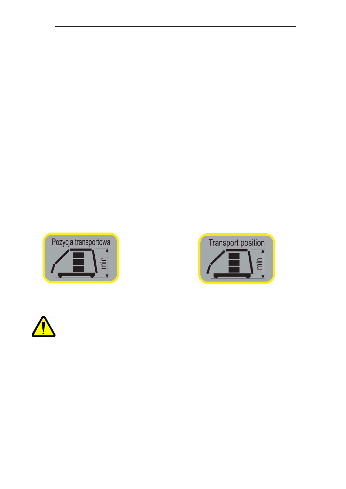
Operating table must be set in transportation position during carrying table by locomotion means
without using table movable system (truck, trolley). Table base and tabletop should be transported in
separate package. Transportation position means that table base is on minimum height and tabletop
in horizontal position with leg segments and head rest. Transportation position is shown on the label
situated on table base and table top. Product should be secured against humidity and stable. In case
of lack of original packaging, the product should be properly secured in order to prevent its damage,
preferably by experienced transport company.
While product transporting, storage and unpacking, the temperature gradient should be less than
10OC per hour. It is strongly recommended to unpack the product after reaching room temperature.
After transporting a product into a building where it is to be installed, a product should be left for at
least 12 hours. Only after this time you can set a product in operation.
Laminar storage is permissible in accordance with the packaging marking. In the absence of the
marking, storied storage is prohibited.
In case of the specific transport conditions (particularly: low temperature transport), it is necessary to
negotiate the way of transport and product packaging with the product manufacturer in order to ensure
safe transport.
A label which indicates product position during transport
A label for the Polish market. A label for foreign countries
Fig. 3 Label “Transport position”
2.2 Unpacking and first use
If the Product is installed by service point of FAMED ŻYWIEC company, User is
released from the responsibility to carry out procedures described in this section.
Caution!
The table is shipped by the producer in an assembled form in a wooden, open-work chest or in a
cardboard box with the following dimensions L: 1340 x W:700 x H:890 mm and weight 160 kg. The
table should be unpacked indoors in order to be protected from damages.
To prepare the table for operation after its transport or delivery one should:
- read product operating manual carefully
- take off the fastening tapes
- remove the package
- remove the materials protecting the table during its transportation
Page
13
Page 14
User manual for Operating table SU-14
If the product is not fully functional, i.e. the output parameters diffe
r from the
Caution!
- take out accessories
- remove elements which block the table base
- place the footrests horizontally (items 3.7 Change of angular position of the footrests and 3.11
Change of angular position of separated footrests)
- release the central blockade (item 3.12 Table mobility)
- with a help of another person carefully take the table from the palette and stop it
- add the headrest (item 3.10 Installation and operation of the headrest)
- place the product in its destination which meets the requirements described in this manual (item
1.2 General requirements),
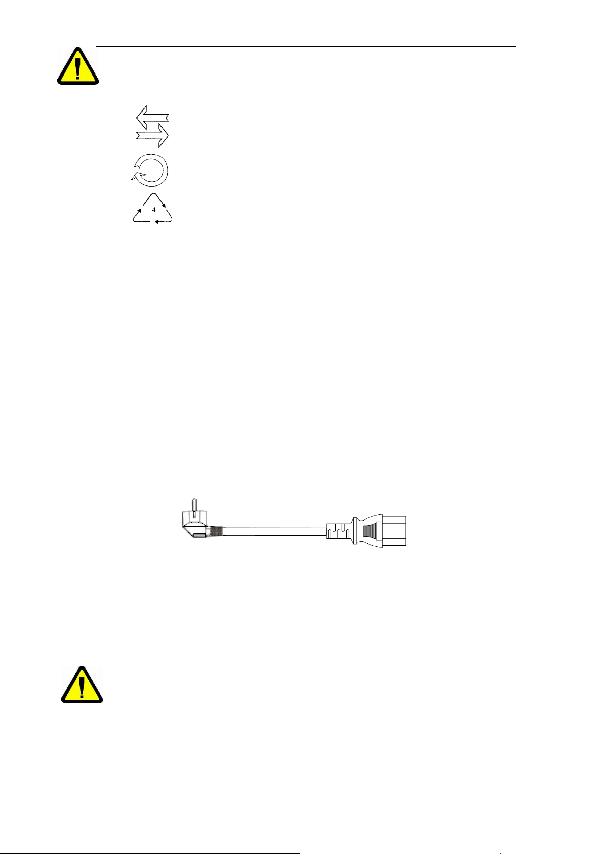
Package may be marked with following signs:
- multiuse package
- package for recycling
- low-density polyethylene packaging
LDPE
Packaging waste disposal should be carried out in accordance to environmental
regulations, that are in force where the packaging containing the Product was
delivered.
Packaging waste are the materials subject to recycling, they should be properly
segregated and passed to selective waste collection point in accordance with
local law regulations.
Returnable packaging must be returned the medical product's supplier.
- Connect the table to the mains voltage of 230V, 50/60 Hz, by connecting the power cord (fig. 1,
Item 27) into the power socket at the base of the table, and then to a wall outlet
-
Fig. 4 Power cord – european version
- connect to the electric mains by connecting of the wire to the socket and charge the batteries,
- on the basis of information given in item 3 Operation check whether the table works as described
in item 5 Criteria on whose basis it is assessed whether product operation is correct or not.
description contained in this manual, the bed must not be used. This situation
should be reported to the producer or supplier. The use of an improperly
Caution!
functioning product may result in damages, which will encumber the user and
which will not be a matter of producer’s responsibility.
Page
14
Page 15
User manual for Operating table SU-14
The wi
re-connected controller is obligatory accessories for surgical tables.
3 Operation and use
3.1 Controlling elements
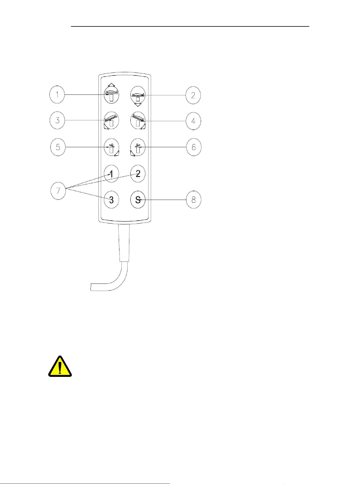
3.1.1 Wire- connected control
1,2 – Height adjusting
3,4 –
5,6 –
Fig.5 wire-connected control
.
The wire-connected control is permanently connected to the controlling box at the table basis. The
table is switch on through place the switching in “I „position (Fig. 1, pos. 17). At this moment the table
is activated and carrying out the movements through pushing the functioning control button is
possible. The buttons [1] to [7] are functioning buttons. When the functioning button is pressed, the
movement represented by button’ symbol is operated so long as the button is pressed.
The wire-connected controller must be on the hand of operating personnel.
To recommended use the operating table connected to net.
Caution!
Longitudinal movement
Side inclination
7 – Memory buttons
8 – Record for memory button
Page
15
Page 16
User manual for Operating table SU-14
3.2 Raising and levering of table top
The height of table top is changed within the range defined in technical data by pressing the button [1]
or [2] of controller (wire-connected controller, wireless controller or side control panel). When the
extreme position is reached, table top stops automatically.
3.3 Table top longitudinal inclination
In order to change longitudinal inclination of table top (trendelenburg and anti-trendelenburg) within
the range indicated in technical data, one should press button [5] or [6] of controller (wire-connected
controller, wireless controller or side control panel). The movement lasts as long as the button is being
pressed. When an extreme position is reached, table top stops automatically.
Angular couch position can be changed only by medical personnel. The
Trendelenburg position is a rescue position.
When performing longitudinal and side tilting functions, patient should be
Caution!
secured against uncontrolled sliding down from the operating table. Use
shoulder supports, supporting rollers, side supports, belts and grips as securing
elements.
When trendelenburg function is performed, the backrest should be in zero
position or above the horizontal level so that no collisions take place!
3.4 Table top side inclination
In order to change side inclination of table top within the range indicated in technical data, one should
press button [5] or [6] of controller (wire-connected controller, wireless controller or side control panel).
The movement lasts as long as the button is being pressed. When an extreme position is reached,
table top stops automatically.
When performing longitudinal and side tilting functions, patient should be
secured against uncontrolled sliding down from the operating table. Use
shoulder supports, supporting rollers, side supports, belts and grips as securing
Caution!
elements.
3.5 Memory of table top position (zero position)
The table controller enable writing 3 any table top position in this memory. Every table top position
may have free height, longitudinal and side inclination. One of this changed position can be the zero
position of table top.
In order to write the position in memory, first should place the required position by means of function
buttons 1-6 on the controller (fig. 4). Press (just a while) the 8 function button of controller (fig. 4). Next
press one of the changed memory buttons-7 (fig. 4), which writes the preset table top position. The
proper writing of position is signalizing by meant of sound signal.
In order to receive the preset position should press one of the function buttons of controller- 7and keep
until receiving the changed position, which is until moment when the table op has been stopped.
In the case of finding the discrepancy between preset and receive position,
one should again carry out the position preset procedure.
Caution!
3.6 Change of angular position of the backrest segment
The angle of the backrest segment (fig. 1, item 2) is changed by the use of the force of muscles with
support of gas spring. In order to adjust a segment position, press blockade (fig.1, pos.20), deviate the
lever (fig. 1, pos.9) to up and then place a segment in a desired position and release a lever (fig.1,
item 9). After releasing a lever, a backrest segment mechanism is blocked and further movement is
prevented. Remember to hold a segment with both hands while adjusting position. Thanks to the
Page
16
Page 17
User manual for Operating table SU-14
If a patient is very heavy, over 90 kg, the angl
e of backrest segment should be
central position of the lever the backrest segment can be operated from the right, from the left and
from behind the backrest segment.
changed with particular care; one should be prepared that it would be necessary to
use considerable force to move it up and to cushion lowering at the moment of
Caution!
lever release (drawing 1 and 2, item 9).
3.7 Change of angular position of the footrests
Angular position of the footrest inclination is changed within the range defined in technical data by
rising of the lever (drawing 1, item 11) or pressing the lever (fig.1, item 22) (on the side removable
footrests) or rising or lowering of the footrest segment to the required level. When the pressure is
removed from the lever, the mechanism is locked and the position of the footrest determined.
Change of the angle between the divided footrests, in the range included in technical data, is obtained
by turning of footrest abduction bolt 3-4 turns (fig.1, item.23) and turning the footrest of the desired
angle to the side.
When the function is performed, the footrests may collide with the base!
Check the proper clamp of the handle that locked the footrest turning.
Caution!
3.8 Insert and take out of footrest
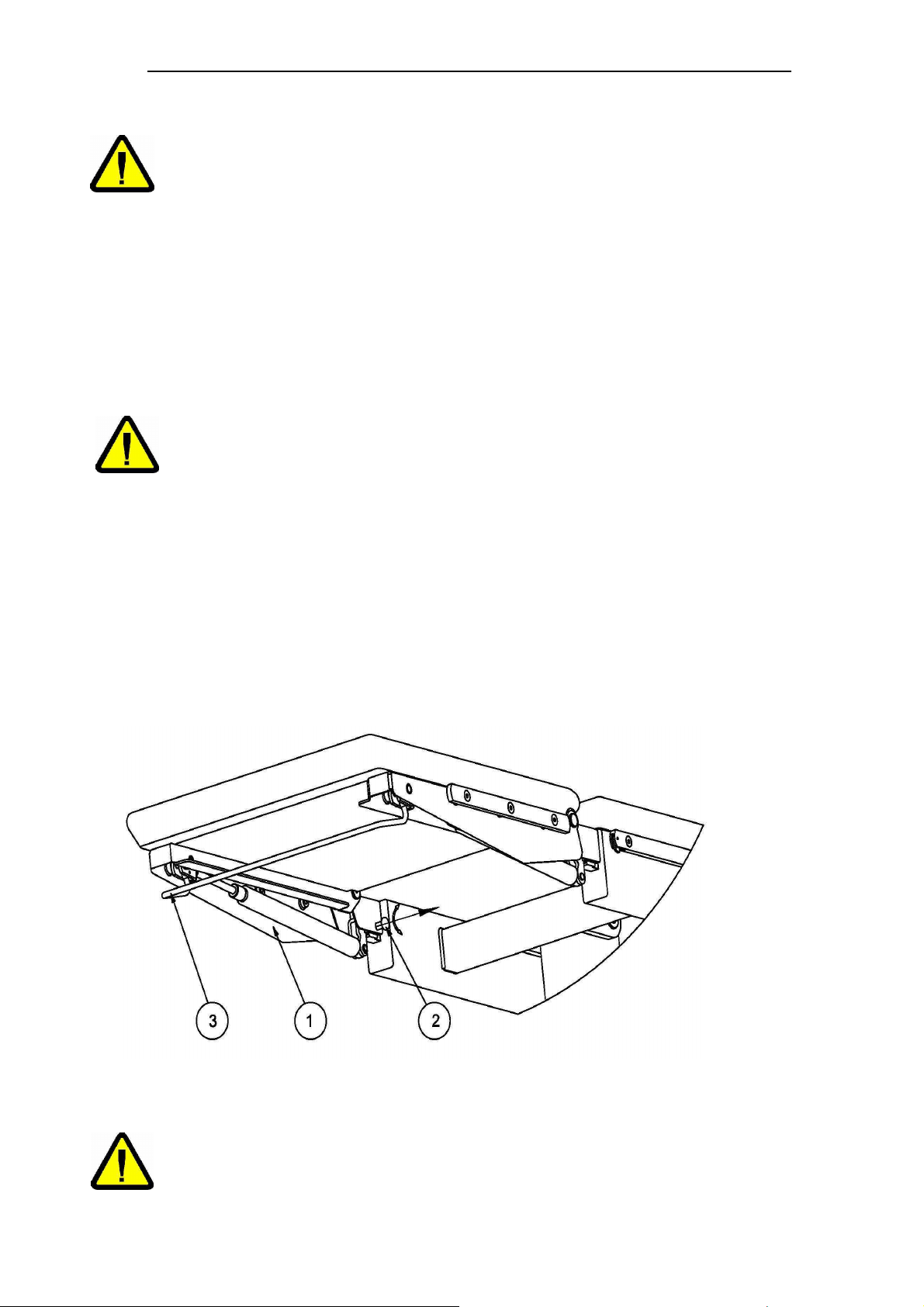
Footrest plate (fig. 5, item 1) is fixed by wedges ( fig. 1, item 10) placed on the bottom of the seat
segment by the blockages placed on both sides of the footrest (fig.5, item 2). Before assembling the
footrest to the seat segment it is necessary to pull out and turn both blockades of the footrest about
90º. After that put on wedge sockets of the footrest on wedge plugs of the seat segment and establish
its position by turning blockades of the footrest up back to the starting position. Disassembly of the
footrest relies on pulling out and turning both blockades of the footrest about 90º and pulling out the
footrests of the wedge plugs of the seat segment. Footrest angle change is obtained by a lever (fig.5,
item 3) activating the gas spring mechanism. Pressing of the lever makes possible the change of
angular position of the footrest. Releasing of the lever provokes blocking of the footrest in chosen
position.
Make sure that the footrest is correctly fixed!
Caution!
Fig. 6
Page
17
Page 18
User manual for Operating table SU-14
3.9 Inserting and Removing Footrest
Footrest segments (Fig. 1, Pos. 4) can be attached and removed from the seat segment thanks to the
mechanism activated by the lever (Fig. 1, Pos. 24). In order to remove the footrest segment, it should
be grasped from underneath, the lever (Fig.1, Pos. 10) should be pulled till its level, and the footrest
segment should be lifted till it comes off the wedge pin located on the seat segment (Fig. 1, Pos.2 4).
Attaching footrest segment consists of raising the lever to its horizontal position (Fig. 1, Pos. 10) and
mounting wedge socket of the footrest on the wedge pin of the seat segment till their levels are even.
After mounting the segment the lever must be lowered (Fig. 1, Pos. 24) back to the starting position
and pressed down
Caution!
.
Make sure that the footrest is correctly fixed!
3.10 Installation and operation of the headrest
The headrest is fastened on installation wedges which are situated at the end of the backrest segment
using a knob. When the headrest is put on the stripe, one should determine its position by screwing
down the screw (fig.1, item 8). The headrest is dismounted by unscrewing of the screw and removal of
the headrest from the stripe. The angle of the headrest is changed similarly to the backrest segment,
that is, by the handle which moves the mechanism of the gas spring. When the lever is pressed (fig.1,
item 6), the required angle of the headrest may be chosen. Its release locks the headrest in the
chosen position.
Make sure that the headrest is correctly locked!
Caution!
3.11 Installation and disassembly of mattresses
All mattresses can be removed without any tools. They are fixed on fixing pegs
3.12 Table mobility
Wheels installed in the base of table make it possible to move it in every direction. The table is
equipped with movement lock used during operations and treatments performed on the table.
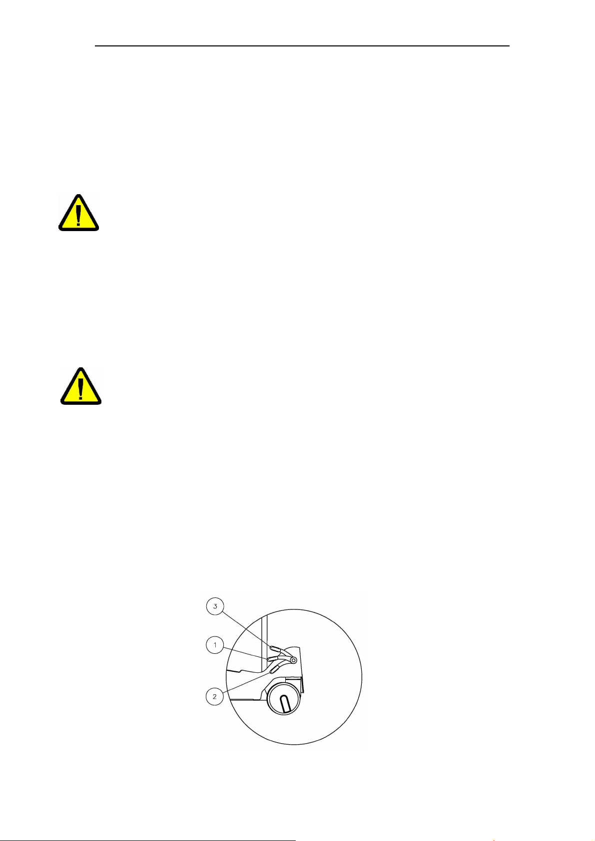
The table is equiped with central blockades of wheels. The central blocking pedal has three position:
- Upper - direction blockade (fig.7, pos.3),
- Middle (horizontal) - blockade released (fig. 7, pos.1),
- Lower - all castors blocked (fig.7, pos.2).
Fig.7
The direction blockade is used during the table movement on long, straight sections and makes it easy
Page
18
Page 19
User manual for Operating table SU-14
If after 12 hours of charging and after disconnecting a power supply cord, it is
The table may not be stored with batteries low.
to turn the table. All castors brake causes a total bed immobilization.
Throughout surgical procedures table wheels should be blocked.
Table should be move by 2 people at least.
Do not move table with workload (patient) through inclines and outside of
Caution!
buildings).
Table should be move in minimal height.
The floor under the table must be free from any obstacles!
When rolling the table avoid collisions!
Do not roll the table over electric cables!
3.13 Antistatic properties
A table structure allows for drainage of electrostatic charge through the following channels:
– By antistatic wheels to conducting floor,
– By potential equalisation clamp.
Operating table SU-14 should be used on antistatic floor. In case of lack of such floor, an electrostatic
charge is drained through a potential equalization line. The potential equalising conductor is a
standard table accessory.
Antistatic properties of the table shall be maintained if mattresses produced by FAMED Sp. z o.o. are
used.
3.14 Potential equalising clamp
Operating table have inside system of potential equalization leading to the clamp (fig. 1, item pos. 16)
marked by symbol .
Throughout surgical procedures the table must be connected to the installation of
potential equalization in the operations room.
Caution!
The cable is provided in standard table accessories
3.15 Collisions
In some extreme positions of the table, in particular, when accessories installed on side stripes are
used, mechanical collisions may take place. Because of that, one should protect the table and
accessories from damages.
3.16 Battery charging
A charger built-in in the table makes it possible to charge the batteries in the table.
In order to charge batteries, connect a power supply cord to a socket in a table and set a switch (fig.1,
item 17) in position „I”. The batteries are charge automatically.
impossible to activate any electrical movements, this means that the table is
damaged. This fact should be notified to an authorized service centre.
Caution!
Table work time is about 10 surgeries from full batteries.
It is required to charge batteries when there is a lack of possibility of carrying out movements or in the
case of noticeable slowdawn of movements.
Battery life time is 3 years.
If batteries need to be exchanged, do always exchange a set of two batteries.
Exchanging a single battery limits an operating time of a table and causes quick
Caution!
wear of a new battery.
Page
19
Page 20
User manual for Operating table SU-14
33 lithotomic stirrups
WS-
64.5 25 kg
4 Installation and operation of accessories
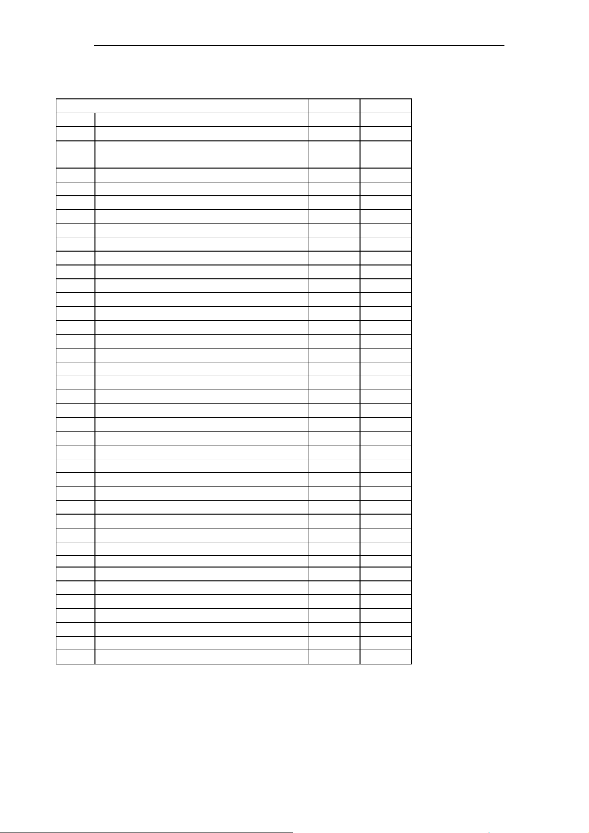
The following extra accessories may be provided with the operating table SU-14:
Elements of accessories Symbol
1 Screen frame WS-01.5 14 kg
2 Screen frame with width regulation WS-01.6 14 kg
3 Hand grip WS-02.5 17 kg
4 Thigh grip WS-03.5 23 kg
5 Shank grip WS-04.5 23 kg
6 Knee support WS-05.5 17 kg
7 Left and right arm support WS-06.5 14 kg
8 Hand angular support WS-07.5 14 kg
9 Big supporting bolster WS-08.5 50 kg
10 Trolley for accessories WS-13.5 50 kg
11 Grip for anaesthesiologist pipes WS-14.5 14 kg
12 Table for tools WS-15.5 14 kg
13 Single position stripe WS-16.5 100Nm
14 Multi position clamp mechanism WS-17.6 100Nm
15 Multi position clamp mechanism WS-17.7 100Nm
16 Hand support WS-22.5 20 kg
17 Complete handrails WS-32.5 23 kg
18 Side x-ray handle WS-33.0 14 kg
19 Wrist grip WS-34.5 14 kg
20 Attachment do arthroscopy WS-39.5 17 kg
21 Attachment for meniscus operation WS-40.5 17 kg
22 Belly belts WS-41.0 125 kg
23 Footrest belts WS-42.0 23 kg
24 Hand belt WS-43.0 17 kg
25 Thigh belt WS-44.0 23 kg
26 Support for hand surgery WS-48.5 17 kg
27 Womb support WS-49.5 40 kg
28 Side support WS-50.5 40 kg
29 Side rest with lever WS-50.6 40 kg
30 Chest rest WS-52.5 40 kg
31 Partial denture of sides shelves WS-53.0 14 kg
32 Shoulder-sides rest WS-59.5 14 kg
34 Mattress for spine WS-65.0 80 kg
35 collar WS-66.0 20 kg
36 Collar under neck WS-68.0 10 kg
37 headrest WS-69.0 10 kg
38 Support for shoulder surgery WS-87.5 14 kg
39 hand rest PR-01.5 20 kg
40 Drip hander WK-01.5 10 kg
When ordering table accessories, please give table’s name and symbol.
The producer reserves the right to modify accessories according to client requirements and
produce new accessories complains with norm of safety.
Page
20
Page 21
User manual for Operating table SU-14
If the product is not fully functional, i.e. the output parameters differ from the
5 Criteria on whose basis it is assessed whether product
operation is correct or not
Correctness of table operation shall be checked every day before the beginning of
its operation.
Caution!
The method of checking whether operation of the table is correct:
1. Check stability of the table when its feet are down by trying to move the table manually ( when the
wheels are blocking): pushing of the table in any direction should not cause tilting or moving.
2. Check mechanisms of adjustment of positions of the segments controlled by gas springs by a
change of position and locking (see item 3 Operation). The mechanism should work without
jamming, after locking the segment should not change its position (check by manual pressing of
the segment).
3. Check if there are no mechanical plays by manually moving the top of the table.
4. Check the work of the electro-mechanics system by performance of all movements controlled by
wire-connected control.
If the table underwent the above described tests with positive results and there were no disturbing
sounds (squeaks and grinds), the table can be used safety.
Otherwise see item 6.6 ‘Location and removal of defects’.
Caution!
description contained in this manual, the bed must not be used. This situation
should be reported to the producer or supplier (dealer). The use of an improperly
functioning product may result in damages, which will encumber the user and
which will not be a matter of producer’s responsibility.
Page
21
Page 22
User manual for Operating table SU-14
6 Technical operations
6.1 Storing
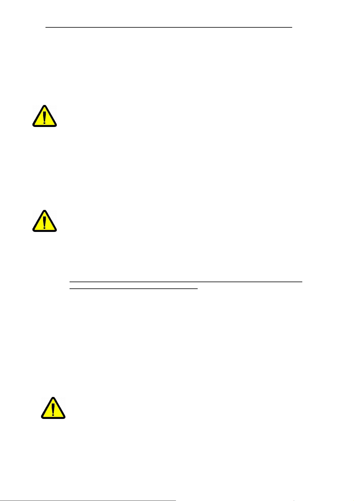
If the product is not to be used for a longer period of time, it should be stored in the below
mentioned climatic conditions:
• temperature: 25º ±10ºC,
• relative humidity: 50% ± 25%.
During storing, the operating table must be turned off. The switch (position 17,
figure 1) must be in the “0” position.
If the table is stored for a longer period of time, it must be connected to the power
Caution!
supply for 24 hours each 6 months to charge the batteries.
The table may not be stored with batteries low
6.2 Cleaning and disinfecting
For cleaning and disinfecting use cleaners, disinfectants recommended by Famed Żywiec Sp. z
o.o. in Annex 2 to this manual (allowed to turnover and use on the territory of the country, where
they are used).
After disinfection the Product should be washed with water to eliminate any stains.
After disinfecting dry thoroughly.
Dry with hot air (maximal temperature 60°C) or by wiping with a soft sterile cloth.
Before disinfecting disconnect the product from mains!
The product/ table must not be disinfected in disinfecting chambers.
Bleaching (containing active chlorine or oxygen), caustic and corrosive agents
Caution!
must not be used.
No disinfecting agents containing alcohol may be applied to elements made of
polyurethane (mattresses)!
No agents destroying the structure of plastic (organic solvents) may be applied to
the plastic elements.
Disregarding the above requirements concerning cleaning and disinfecting shall
result in losing the guarantee for the product
.
6.3 Damages and defects
Damages and defects found in the product or product accessories should be reported immediately
to a person in charge of such issues. The bed which can not be safely operated (e.g. damaged
electric or mechanical elements ) must not be used till it is repaired.
6.4 Repairs and conservation
Repairs are done by the producer. The user can not carry out any repairs on his own unless he
has undergone special training or has been authorised to do that. When the producer has given
his written permission for repair of the product by client’s technical staff, the producer shall provide
the client with necessary charts, lists of spare parts, descriptions and information on repairs.
The producer allows only using original spare parts. In order to provide safe and reliable operation
of the product one should use only spare parts provided by the producer. Worn out parts shall be
removed as provided in environmental protection regulations
The product contains products which may be dangerous to the environment:
- a battery integrated with controller – type BA 1812V 1,2Ah (2pieces).
The rules of proceeding with used products which may be dangerous to the
Caution!
environment are defined in environmental regulations.
If there is a need to replace the batteries, used batteries are collected by the
medical device's producer or an authorised service point indicated by the
producer.
Used batteries receives a medical device manufacturer or indicated by the
authorized repairer or Third Party having required by environmental law
decisions to conduct.
Page
22
Page 23
User manual for Operating table SU-14
Repairs and maintenance must be performed only by qualified personnel. If a product is operated
outside Poland, one should inform about a necessity of a repair a producer or the dealer from
whom the product was purchased.
Every repair of the product should be recorded on the list of repairs enclosed to the
guarantee card on pain guarantee loss!
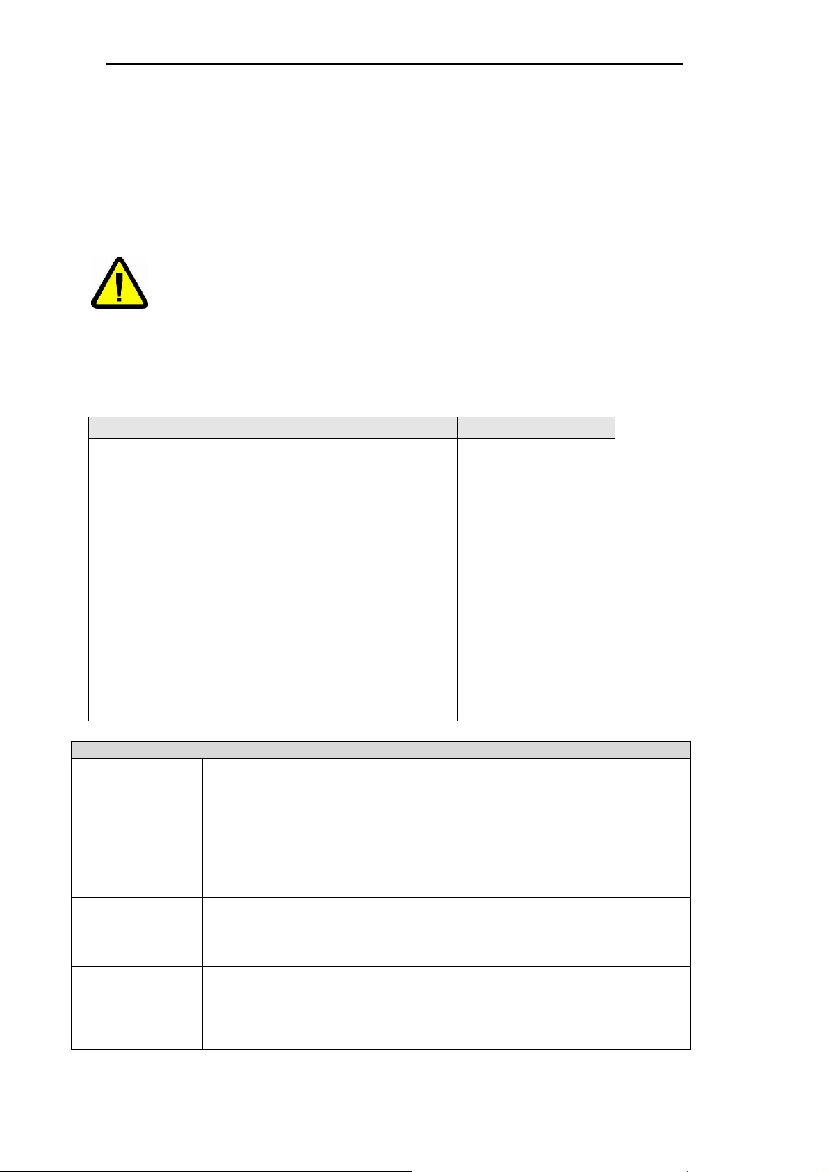
6.5 Control of technical condition
To ensure safety and proper technical condition of the product, User is required to have it
undergone periodic technical inspections. These inspections are carried out at the user's expense,
by the Producer or customer's qualified technical staff.
Periodic inspections of the table must be recorded in the Device Passport or the
product’s warranty card.
Caution!
• IEC 62353 (Table 1) compliance check
• General technical condition check (Table 2)
• Checking safety and functions
– check of functioning of remote operated
functionalities
– check of reset function — calibration of
inclinometers
– checking collision limits
– checking antistatic parameters of mattresses.
Resistance value shall be within the range from 104 to
106Q
– Check of electric connections.
– Check of base and column condition.
– Check of mechanical connections.
– Check of longitudinal movement function.
– Check of battery capacity.
– Check of play on the column.
Visual inspection
Measurements
Functional test
Technical inspections of the product must be recorded on the list of repairs
enclosed with the guarantee certificate.
After the product's period of use expires, permission for further use is granted
after positive result from technical inspection carried out in authorised service
point. Each time a permission is granted for 12 months.
Subject of inspection frequency
Every 12 months
Scope of inspection in line with IEC 62353
• Checking all fuses accessible from the outside, and their conformity with
documentation (fuse capacity, characteristics),
• Checking if all markings and labels are in place and legible,
• Checking if all mechanical parts are in place,
• Checking for damages and checking the cleanliness of the device,
• Checking accessories,
• Checking product documentation and documentation of previous
inspections.
• Measurement of protective earthing resistance,
• Measurement of leakage currents,
• Measurement of patient’s leakage current,
• Measurement of insulation resistance.
• The functional test must be carried out by a suitably experienced person
and trained in operation of the device.
• The functional test and the results of specific tests and measurements
should
be documented
Page
23
Page 24
User manual for Operating table SU-14
When to do the inspection:
– the device has been repaired;
– periodically (every 12 months) during technical inspection.
To ensure safe and correct operation of the device during the service life, the user must perform
technical checks listed below every 6 months.
Scope of technical condition check
- Check of all mechanical functions by executing all movements in line with the technical
specification parameters:
– Checking the table movement capabilities.
– Checking central wheel lock.
– Checking the removal and installation of removable segments.
– Checking the load bearing plates under mattresses.
– Check all visible bolted connections without removing housing.
– Check for mechanical play and if all locks work.
– Check the condition of the power supply cable.
– Check the insulation of wired controller cable.
– Check the condition of columns cover.
– Check condition of mattresses.
– Check efficiency of the central wheel lock.
An inspection should involve a visual inspection and the noticed malfunctions should be handled
as provided in item 6.6 Location of defects and their removal.
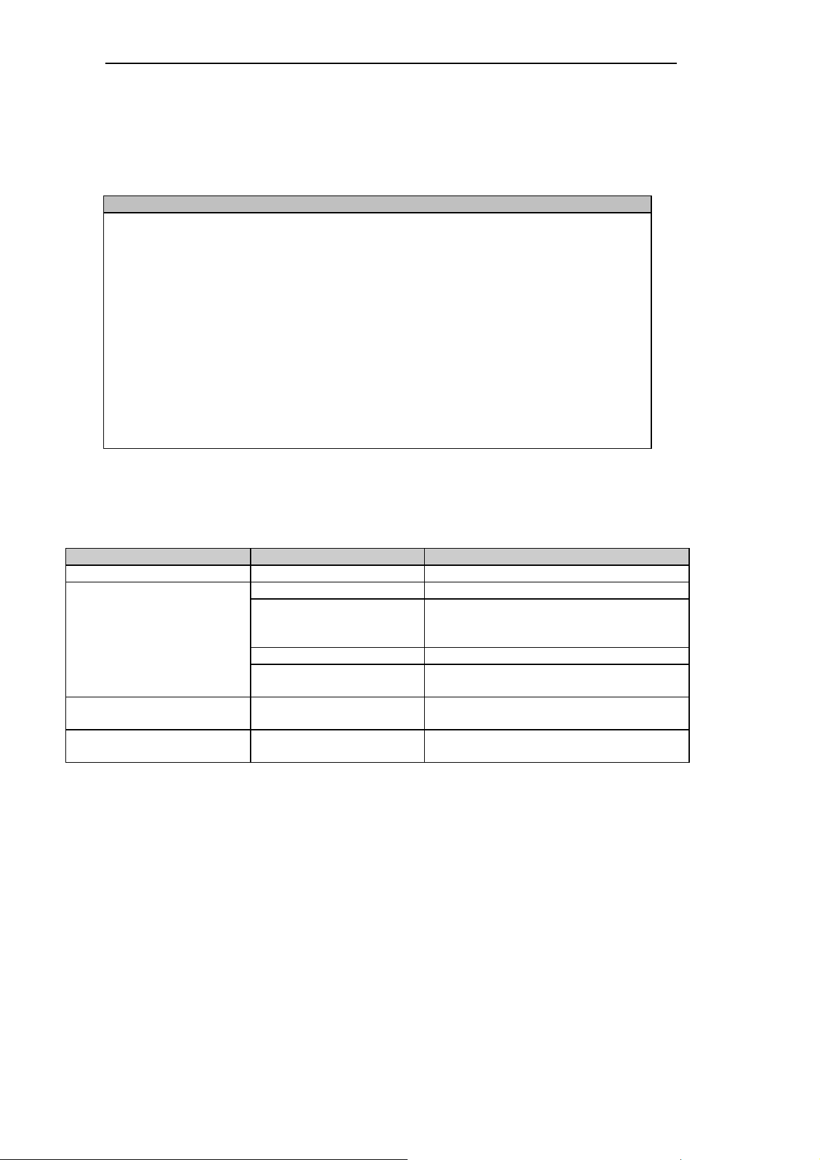
6.6 Location of defects and their removal
damage Possible cause removal
The table cannot be moved locked wheels Unlock blockade pedal
Batteries discharged Charge the batteries
Control plug incorrectly
Plays in screw joints
Lack of possibility of using
the preset position
plugged to the socket in
the table
Damaged pilot Contact your service
Blockage of the driver
Plays appeared during
product operation
Change of position setting Insertion again the position to memory
Plug in the plug correctly
Disconnect the table of the alimentation,
wait few seconds and reconnect.
Screw down with generally available
wrenches
according to point 3.5
If a fault can't be eliminated, abstain from using the product and report the matter in the Service
Department, or service of FAMED ŻYWIEC company.
6.7 Product liquidation
If the customer resigns from further product exploitation, he is obliged to product liquidation
according to rules of environment protection; detailed information is situated in annex no. 3.
Page
24
Page 25
User manual for Operating table SU-14
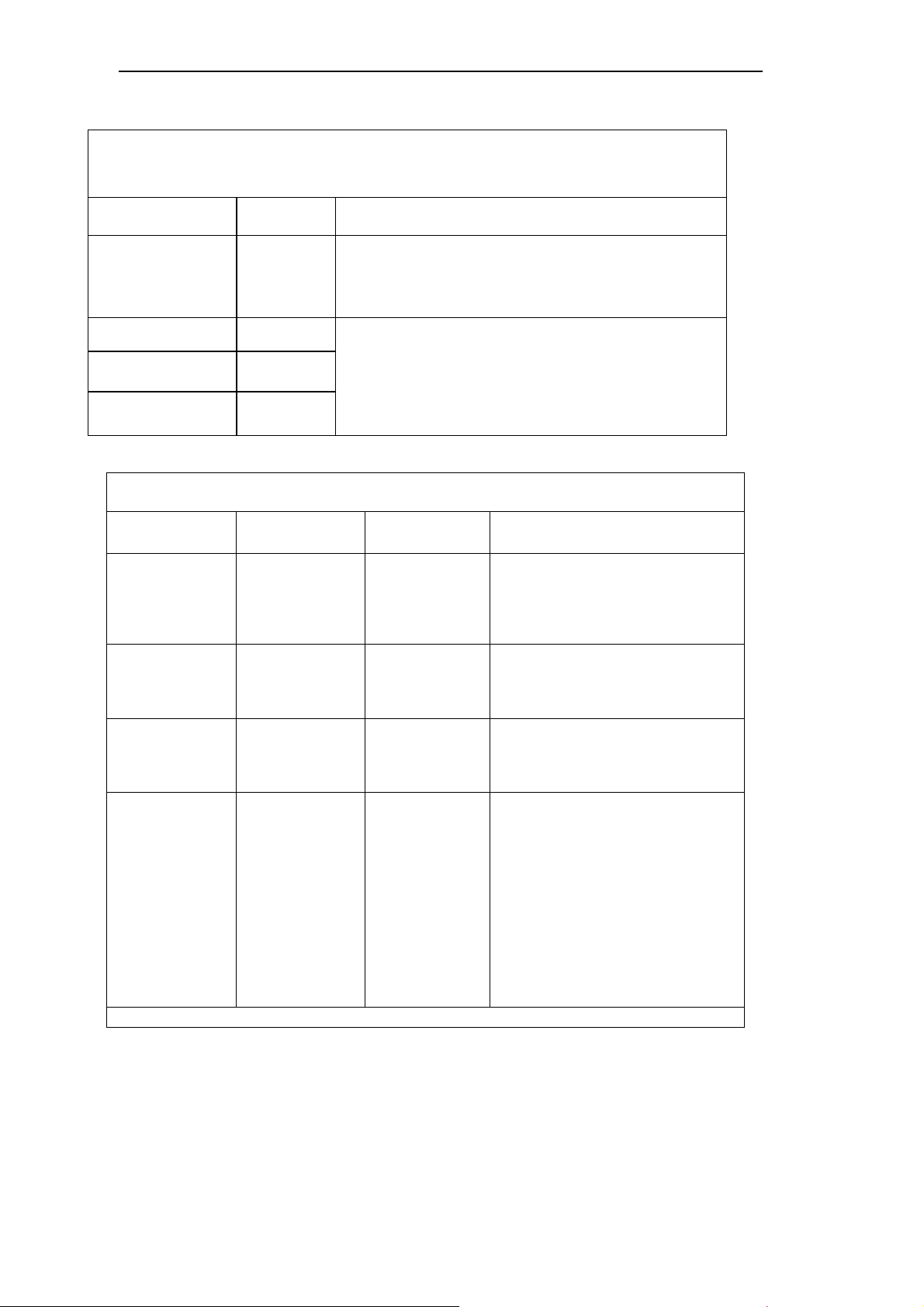
Medical device
operating table
SU-14 is to be used in electromagne
tic environment
Type of emission
Classification
Explanations and instructions
Medical device operating
table SU
-
14 produces energy
with radio frequency only for its internal function.
Therefore, its RF emission are very low and are not
likely to cause any interference in nearby electronic
Medical device operating t
able SU
-
14 is suitable for use
in all establishments, including domestic establishments
voltage
power supply network that supplies buildings used for
Voltage fluctuation,
IEC 61000
-3-3
±
±
±
±
7 Characteristics of electromagnetic environment
Electromagnetic emissions
specified below. The customer or the user of medical device the SU-14 should assure that it
is used in such an environment
Emission
RF CISPR
11
Group 1
equipment..
emission
RF CISPR
Harmonic emission
IEC 61000-3-2
flickering
Class B
Class A
Complies
and those directly connected to the public lowdomestic purposes.
Electromagnetic immunity
Medical device operating table SU-14 is to be used in electromagnetic environment specified below. The
customer or the users of medical device the SU-14 should assure that it is used in such an environment.
Immunity test
Electrostatic
discharge (ESD)
IEC 61000-4-2
Surge
IEC 61000-4-5
Series of quick
transitory stages
IEC 61000-4-4
Voltage dips, short
interruption and
voltage variations on
power supply input
lines
IEC 61000-4-11
NOTE UT is the a.c. mains voltage prior to application of the test level
IEC 60601-1-2
Test level
± 6 kV contact
± 8 kV air
1 kV differential
mode
± 2 kV common
mode
2 kV for power
supply lines
± 1 kV for input/
output lines
< 5% UT
(>95% dip UT)
for 0.5 cycle
40% UT
(60% dip UT)
for 5 cycles
70% UT
(30% dip UT)
for 25 cycles
< 5% UT
(>95% dip UT)
for 5 seconds
Compliance level Electromagnetic environment – guidance
± 6 kV contact
± 8 kV air
1 kV differential
mode
± 2 kV common
mode
2 kV for power
supply lines
± 1 kV for input/
output lines
< 5% UT
(>95% dip UT)
for 0.5 cycle
40% UT
(60% dip UT)
for 5 cycles
70% UT
(30% dip UT)
for 25 cycles
< 5% UT
(>95% dip UT)
for 5 seconds
In the location of SU-14 use the floor should
be wooden, concrete or covered with
ceramic tiles. If the floor is covered with a
synthetic material, the relative humidity
should be at least 30%.
Mains power quality should be that of a
typical commercial or hospital environment
Mains power quality should be that of a
typical commercial or hospital environment.
Mains power quality should be that of a
typical commercial or hospital environment.
In normal use operating table SU-14 is
battery operated.
Connect to mains network only for battery
charging.
Page
25
Page 26
User manual for Operating table SU-14
Electromagnetic immunity
Medical device operating table SU-14 is to be used in electromagnetic environment specified below. The
customer or the user of medical device the SU-14 should assure that it is used in such an environment.
Immunity test
Transmitted
disturbances induced
by fields with radio
frequencies
IEC 61000-4-6
Electromagnetic field
with radio frequency
IEC 61000-4-3
a Field strength from fixed transmitters, such as base stations for radio (cellular/cordless) telephones and land
mobile radio, amateur radio, AM and FM radio broadcast and TV broadcast cannot be predicted theoretically
with accuracy. To assess the electromagnetic environment due to fixed RF transmitters, an electromagnetic
site survey should be considered. If the measured field strength in the location in which medical device the
operating table SU-12 is used exceeds the applicable RF compliance level above, the operating table SU-12
should be observed to verify normal operation. If abnormal performance is observed, additional
measures may be necessary, such as reorienting or relocating medical device the operating table SU-12.
b Over the frequency range 150 kHz to 80 MHz, field strength should be less than 3 V/m.
NOTES
These guidelines may not apply in all situations. Electromagnetic propagation is affected by absorption and
reflection from structures, objects and people.
IEC 60601-1-2
Test level
3 Vrms
150 kHz to 80 MHz
3 V/m
80 MHz to 2.5 GHz
Compliance level Electromagnetic environment – guidance
3 Vrms
3 V/m
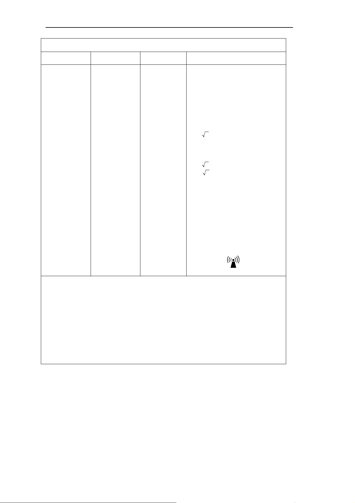
Portable and mobile RF communications
equipment should not be used closer to any
part of the operating tables SU-12, including
cables, than the srecommended separation
distance calculated from the equation
applicable to the frequency of the
transmitter.
Recommended separating distance:
Pd 2,1=
80 MHz to 800 MHz
Pd 2,1=
800 MHz to 2.5 GHz
Pd 3,2=
Where P is the maximal output power of the
transmitter in watts (W) according to the
transmitter manufacturer and d is the
recommended distance in meters (m).
Field strengths from fixed RF transmitters,
as determined by an electromagnetic site
survey, a should be less than the
compliance in each frequency range
Interference may occur in the vicinity of
equipment marked with following symbol:
Page
26
Page 27
User manual for Operating table SU-14
8 Table identification
When sending/ asking any questions concerning the table and when ordering spare parts, please
give the serial number of the table placed on the nameplate and the guarantee certificate.
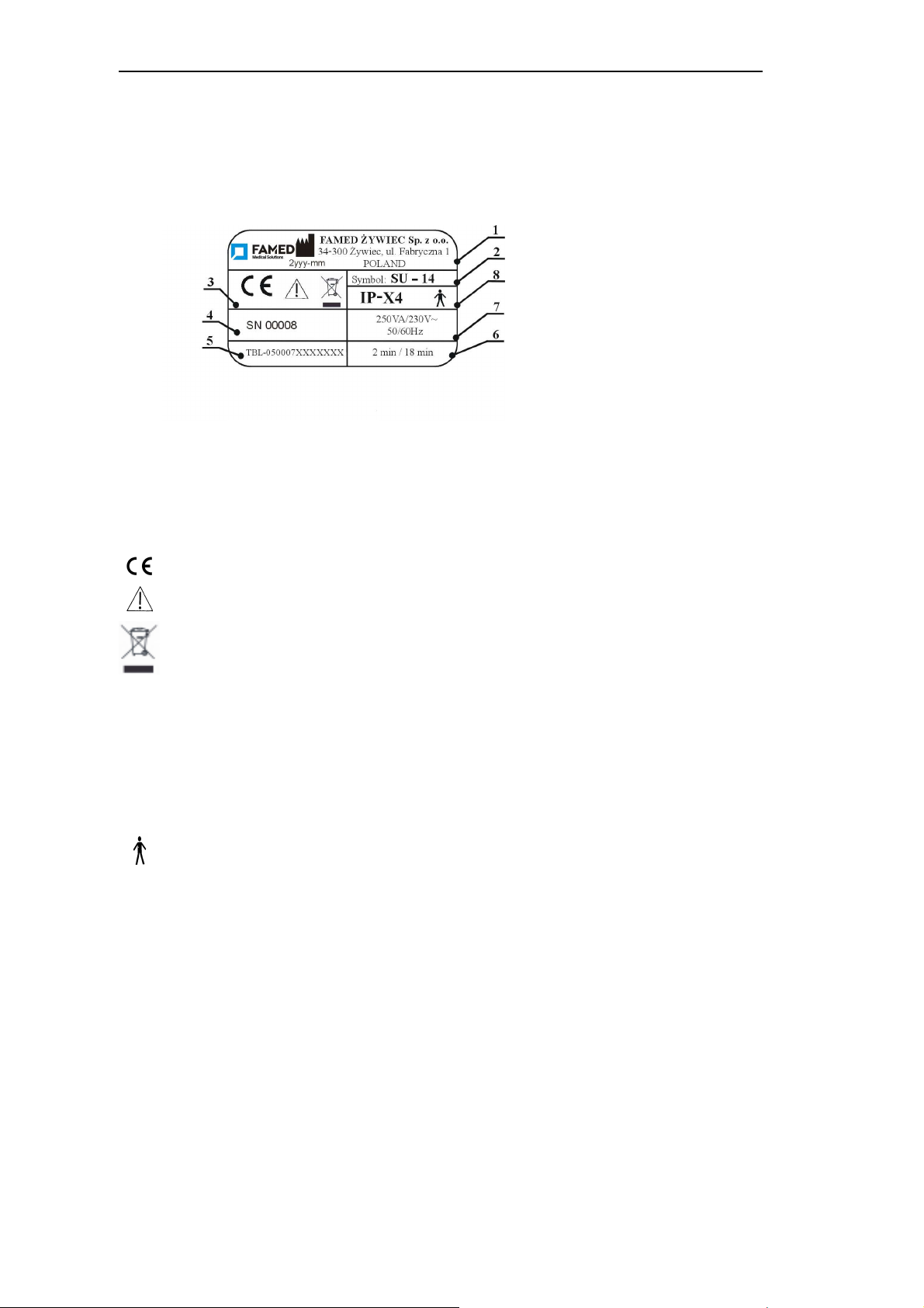
8.1 Nameplate
Description of meanings of particular boxes of a name plate
1 – Name, logo and address of the Manufacturer,
2 – Product symbol,
3 – General markers,
CE mark,
"Warning! - Follow the instructions for safe use ".
Caution! – During disposal of the product, one should act according to the Act concerning
electrical and electronic equipment waste
4 – Product trade number with untypical order number (if applicable)
5 – Index of the product,
6 – Class of duty,
7 – Power supply specification
8 – Additional markings
IP-X4
Degree of protection
.
Application part B
Page
27
Page 28
User manual for Operating table SU-14
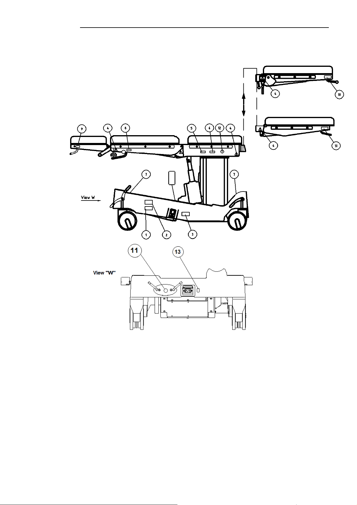
8.2 Labels
Page
28
Page 29
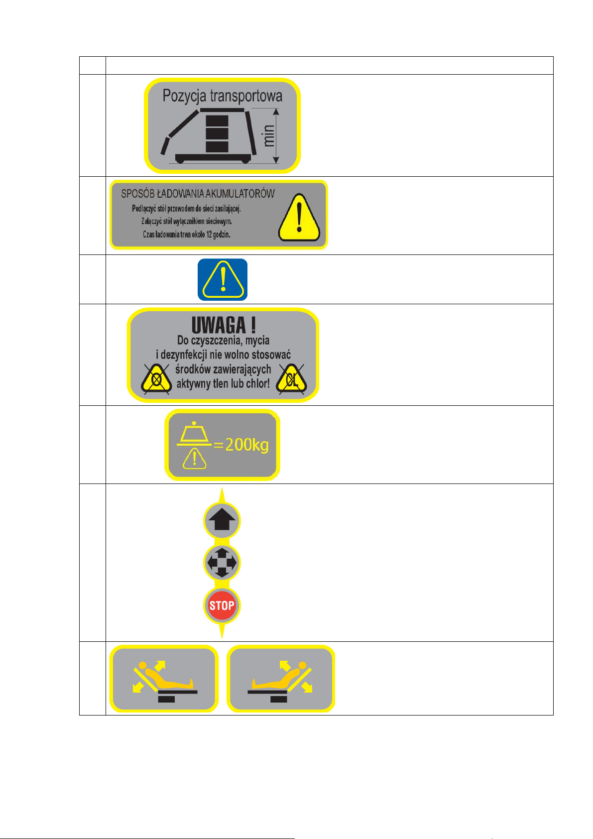
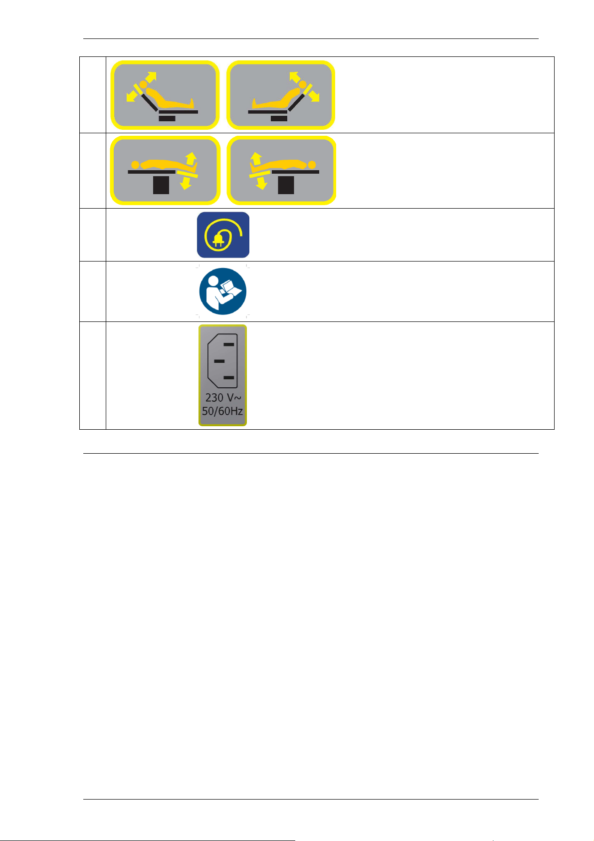
1 Watch point 8.1 Name plate
2
3
4
5
Transport position of the table (see point (see
point 2.1)
The method of battery charging
Warning! - Follow the instructions for safe use.
For clearing and disinfection you should not
use agents containing active oxygen and
chlorine
6
7
8
Maximal workload 200 kg
Central wheels blockade
Back rest adjustment
Page 30
Operating manual for Operating Table SU-12
9
10
11
12
13
Head rest adjustment
Foot rest adjustment
Hook for alimentation cable
Follow the instructions
Power socket
Notice! The producer reserves the right to introduce in the product
structural modifications resulting from technical progress which are not
covered in this operating manual.
Page 30
Page 31
Operating manual for Operating Table SU-12
Item:
SU-14
Edition:
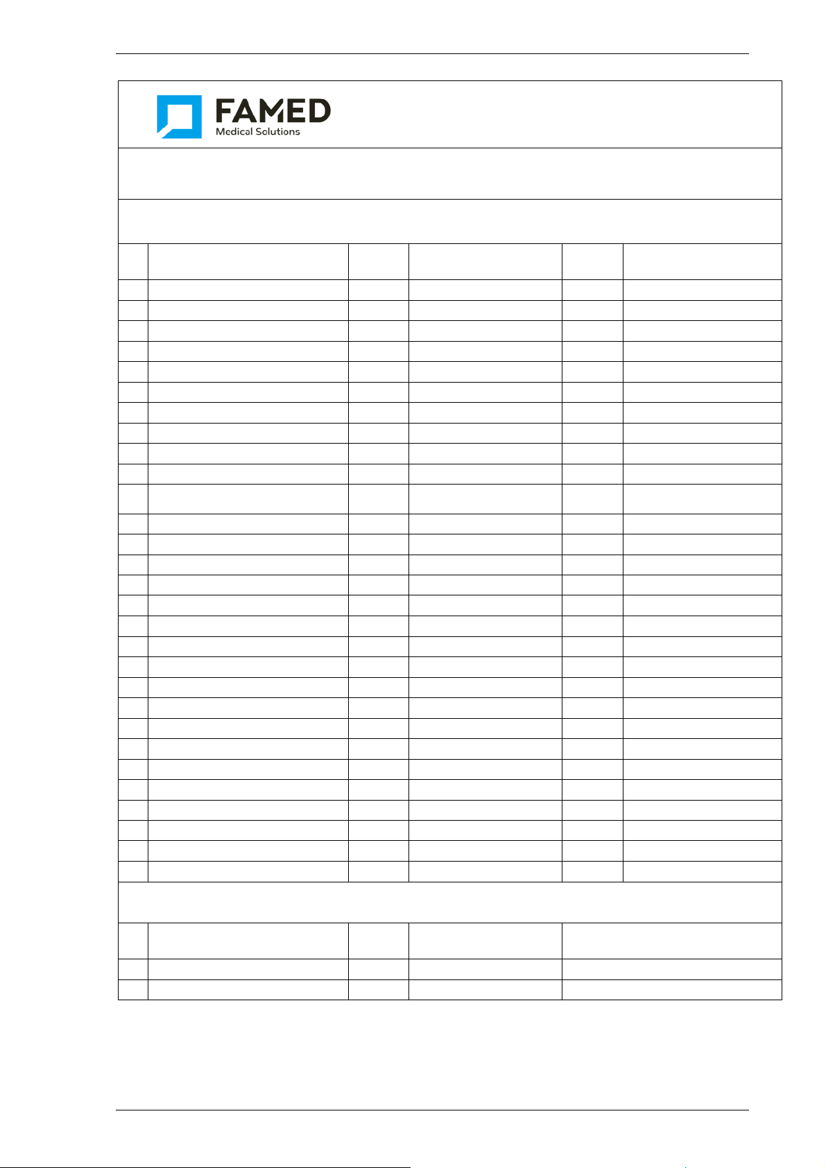
Spare Parts List
Basic spare parts
No. Name Qt. Code number Category
1
Column
2
Control box
3
Brake lever
4
Caster
5
Caster
6
Caster
7
Pilot sleeve I
8
Sliding sleeve
9
Pin I
10
Pin II
Motive system of head rest
11
section
12
Driving unit of backrest
13
Head rest matress
14
Earthing screw
15
Base cover
16
Lock pedal left
17
Lock pedal right
18
Back rest mattress
19
Servo-motor for Trendelenburg
20
Servo-motor of heel side
21
Backrest rail
22
Seat mattress
23
Seat pin
24
Manual control device ( pilot)
25
Side strip
26
Mattress of footrest
27
Driving unit of foot stool L+P
28
Handwheel
29
Stopper
1
1
1
1
1
2
2 C073600000014/-01/ 2 Famed Żywiec Sp. z o.o.
4
3
1
1
2
1
1
1
2
2
1
1
1
2
1
2
1
2
1
2
2
2
August 2014
S09164004010310
S09164004020710
C043306000501/-02/
S06549041501031
S06549041501030
S06549041502014
S30250100000200
C183600000005
C183600000006
C183701020000
C183702050000
C183701000005
C028001010088000
C183600000016
S06549065006020
S06549065006021
C183702000003
S09164004005711
S09164004003111
C183702000004
C183703000003
C183703000004
S09164004025510
C047311000019
C183704030005
C183704080000
S13622900000867
S13622900010250
3 Famed Żywiec Sp. z o.o.
1 Famed Żywiec Sp. z o.o.
2 Famed Żywiec Sp. z o.o.
3 Famed Żywiec Sp. z o.o.
3 Famed Żywiec Sp. z o.o.
3 Famed Żywiec Sp. z o.o.
2 Famed Żywiec Sp. z o.o.
2 Famed Żywiec Sp. z o.o.
2 Famed Żywiec Sp. z o.o.
2 Famed Żywiec Sp. z o.o.
2 Famed Żywiec Sp. z o.o.
2 Famed Żywiec Sp. z o.o.
2 Famed Żywiec Sp. z o.o.
2 Famed Żywiec Sp. z o.o.
2 Famed Żywiec Sp. z o.o.
2 Famed Żywiec Sp. z o.o.
2 Famed Żywiec Sp. z o.o.
2 Famed Żywiec Sp. z o.o.
2 Famed Żywiec Sp. z o.o.
2 Famed Żywiec Sp. z o.o.
1 Famed Żywiec Sp. z o.o.
1 Famed Żywiec Sp. z o.o.
1 Famed Żywiec Sp. z o.o.
1 Famed Żywiec Sp. z o.o.
3 Famed Żywiec Sp. z o.o.
3 Famed Żywiec Sp. z o.o.
3 Famed Żywiec Sp. z o.o.
2 Famed Żywiec Sp. z o.o.
SJW-4-01-02
Remarks
Repair kit
No.
1
2
Name Qt. Code number Remarks
Page 31
Page 32

Legend:
Markers in column „Category”
1 - The elements endanger fast wear out
2 - The elements not endanger fast wear out
3 - The elements wear out depended of condition of exploitation
Operating manual for Operating Table SU-12
Page 32
 Loading...