

Page 1
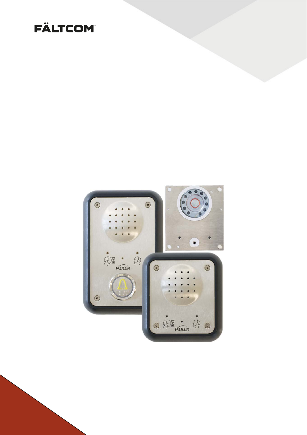
Fältcom ECII® Flex
Manual
Version: 0.2.4-D
Page 2
Fält Communications 201 6 ©
162187 Manual Fältcom ECII® Flex V024D 2016-02-23 Page 1 of 41
Page 3

Table of contents
NOTES ...............................................................................................................................4
1
2 COPYRIGHT ......................................................................................................................4
3 DECLARATION OF CONFORMITY .................................................................................4
4 PRODUCT DESCRIPTION ................................................................................................5
4.1 Design and function...................................................................................................5
4.2 Multiple lift phone connection ....................................................................................7
4.3 Programming and testing ..........................................................................................7
5 INSTALLATION INSTRUCTIONS ....................................................................................8
5.1 Frame mounting ........................................................................................................8
5.2 Mounting behind the car operating panel ..................................................................8
5.3 Connection to alarm button .......................................................................................9
5.3.1 Closing alarm button function ...............................................................................9
5.3.2 Separate alarm button(s) ......................................................................................9
5.4 Connection to telephone line .....................................................................................9
5.4.1 Connection to telephone switches and other devices ..........................................9
5.4.2 Connection with separate suspension cable ..................................................... 10
5.4.3 Flat cable type .................................................................................................... 10
5.4.4 Connection via existing cable ............................................................................ 11
5.5 Connection of voltage supply ................................................................................. 11
5.6 Connection to loop amplifier ................................................................................... 12
5.7 Connection of external pictogram .......................................................................... 12
5.8 Connection to Intercom (art. 2153) ........................................................................ 12
5.9 Connection to additional Alarm buttons ALBU (art. 2142) ..................................... 12
5.10 Connection to Speech Unit (art. 2230) ................................................................... 12
6 PROGRAMMING ............................................................................................................ 13
6.1 Configuration settings............................................................................................. 13
6.2 Activation of programming mode ........................................................................... 14
6.2.1 First time used of if unit is powerless ................................................................. 14
6.2.2 Reprogramming an Fältcom ECII® Flex ............................................................ 14
6.2.3 Reprogramming from phone .............................................................................. 14
6.2.4 Indication and exit .............................................................................................. 14
6.3 Reset to factory settings ......................................................................................... 15
6.4 Clear all active alarms ............................................................................................ 15
6.5 Change of PIN code ............................................................................................... 15
6.6 Alarm receivers and alarm codes ........................................................................... 15
6.7 Prefix in a PABX switch board ............................................................................... 16
6.8 Alarm input setting .................................................................................................. 16
6.9 Test of alarm reception........................................................................................... 18
6.10 Change of time delay for alarm button ................................................................... 19
6.11 Connections to telephone line with automatic dial/ connection. ............................ 19
6.12 Automatic test alarm/routine call ............................................................................ 20
6.13 Incoming calls ......................................................................................................... 21
6.13.1 Multiple units on the line ................................................................................ 22
6.13.2 Single unit on the line .................................................................................... 22
Fält Communications 201 6 ©
162187 Manual Fältcom ECII® Flex V024D 2016-02-23 Page 2 of 41
Page 4

6.13.3 Active alarm mode ......................................................................................... 23
6.14 Answering time for incoming calls .......................................................................... 23
6.15 Technical & Battery alarm receiver ........................................................................ 24
6.15.1 Battery alarm from Power Supply (art. 2001) ................................................ 24
6.15.2 Battery alarm from a GSM Gateway (art. 2236) ............................................ 25
6.16 Simplified acknowledgement .................................................................................. 25
6.17 321 – Disconnection of acknowledgement ............................................................ 26
6.18 323 – Acknowledge on end .................................................................................... 26
6.19 Detection of busy alarm receiver ............................................................................ 27
6.20 LED flashing sequence .......................................................................................... 27
6.21 Programmable alarm types .................................................................................... 28
6.22 Info Alarm – logging of alarms ............................................................................... 29
6.23 End-of-alarm ........................................................................................................... 30
6.23.1 End-of-alarm receiver .................................................................................... 31
6.24 Alarm protocol ........................................................................................................ 32
6.25 Dial tone detection .................................................................................................. 32
6.26 Speech messages .................................................................................................. 32
7 ALARM RECEPTION ..................................................................................................... 34
7.1 Alarm call ................................................................................................................ 34
7.2 Acknowledging an alarm ........................................................................................ 34
7.3 Ending a call ........................................................................................................... 35
7.4 Repeat Message 2 ................................................................................................. 35
7.5 Forwarding a call .................................................................................................... 35
7.6 Termination of active alarm mode .......................................................................... 35
7.7 Speech switching ................................................................................................... 35
7.8 Calls to a lift phone ................................................................................................. 35
7.8.1 Multiple units on the line .................................................................................... 35
7.8.2 Single unit on the line ......................................................................................... 36
7.9 Volume control ....................................................................................................... 36
8 PRODUCT LABEL ......................................................................................................... 37
9 WARRANTY ................................................................................................................... 37
10 UPDATES ....................................................................................................................... 38
11 REPAIR RETURN PROCEDURE .................................................................................. 38
12 TECHNICAL DATA ........................................................................................................ 39
13 CONTACT INFORMATION ............................................................................................ 40
Fält Communications 201 6 ©
162187 Manual Fältcom ECII® Flex V024D 2016-02-23 Page 3 of 41
Page 5

1 Notes
We would like to thank you for placing your confidence in F ält Communications AB and we
are convinced that the choice of one of our security products will fulfill your expectatio ns. In
order to operate this Fältcom ECII® Flex correc tly we w ould as k you to read this manual car efully prior to using it.
2 Copyright
This document belongs to Fält Com m unications AB, a nd m ay only be re produce d, adap ted or
transcribed following written permission from copyright proprietor. Copyright © 2008-2010
3 Declaration of Conformity
We, Fält Communic ations AB, Vasagatan 23, S-90329 Umeå, Swede n hereby declare that
this product, Fältcom ECII® Flex 2187, conforms with the directives: R&TTE 1999/5/EC,
EMC 2004/108/EC, LVD 2006/95/EC, W EEE 2002/96/EG and RoHS 2002/ 95/EG. The product complies with the following standards/norms: EMC: EN 12015(2004), EN 12016(2004),
EN 50130-4(1995) and A1(1998) and A2(2003), EN 55022(2006) and A1(2007), EN
55024(1998) and A1(2001) and A2(2003), Lift Safety: EN 81-1/2, EN 81-28 and EN 81-70.
Umeå, Sweden, April 2009
Mikael Långström, CEO
Fält Communications AB
Fält Communications 201 6 ©
162187 Manual Fältcom ECII® Flex V024D 2016-02-23 Page 4 of 41
Page 6
Microphone
Lift phone
4 Product description
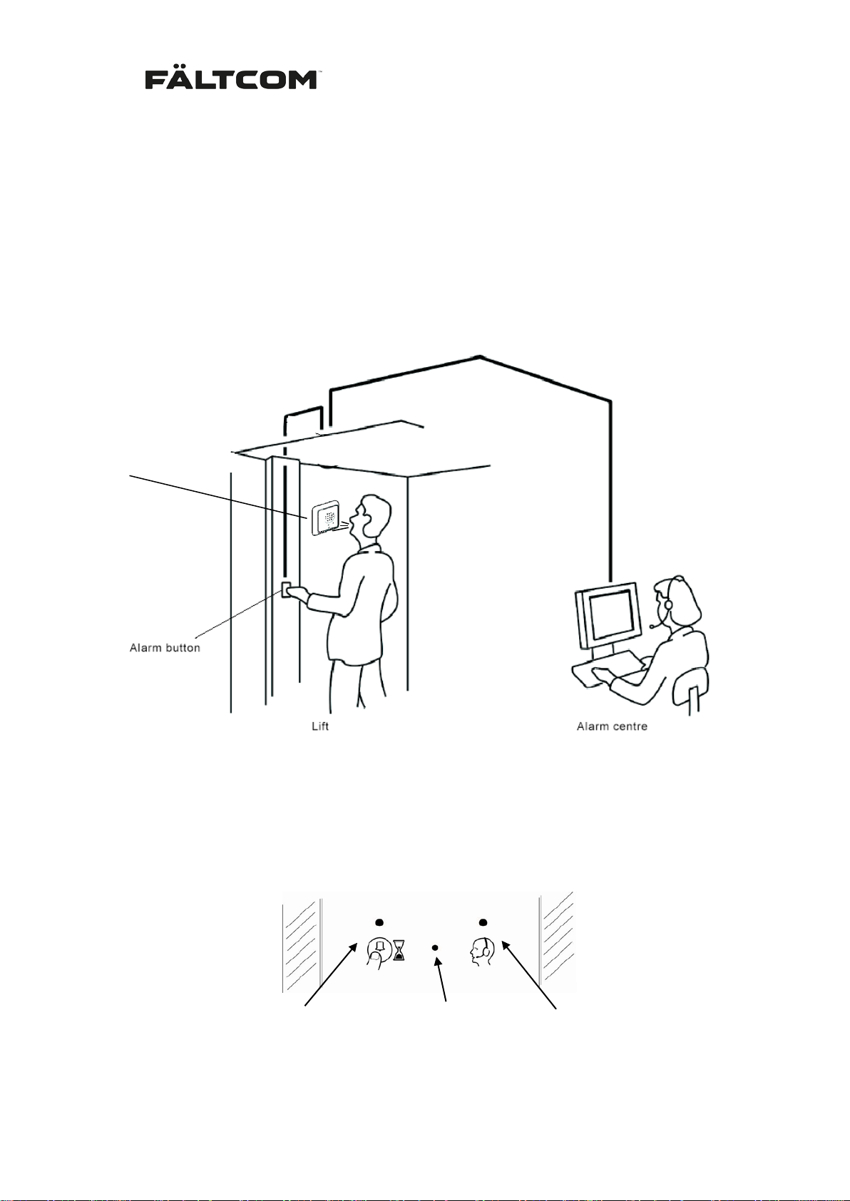
The Fältcom ECII® Flex is an alarm equipment for the PSTN network with built in duplex
speech communication designed for installation in lifts.
When a lift passenger pres ses the butto n f or alar m /emergenc y signal , the l ift pho ne aut om atically calls up an alarm centre or some other predef ined alarm r eceiver. Voice comm unication
is established and the pers on in distress can talk to the staff at the alarm c entre, from where
help will be dispatched.
Fältcom ECII® Flex
4.1 Design and function
The lift phone des ign facilitates mounting. Lou dspeaker, microphone, a ll the electronics, the
keys for programm ing and t esting , as wel l as all con ne c tion po ints ar e i nte grat e d in one s in gl e
unit. This gives quick and easy installation as well high r eliability in operation. The lift pho ne
speaker sound is easily adjusted with a trim potentiometer.
LED 1
(yellow)
LED 2
(green)
Fält Communications 201 6 ©
162187 Manual Fältcom ECII® Flex V024D 2016-02-23 Page 5 of 41
Page 7
On the lift phone’s front pl ate, there are two pictogram s and two single colored LED (yellow
and green), which are normally turned off. The left LED b ec omes yellow when an a larm call is
in progress and the right LED becomes gr een w hen t he a larm has been ack no wledge d by the
receiver and a speec h connection is established. T he LED’s are also us ed to indicate programming mode. T he LED’s can be programm ed to display other light sequenc es, see section Programming for more information.
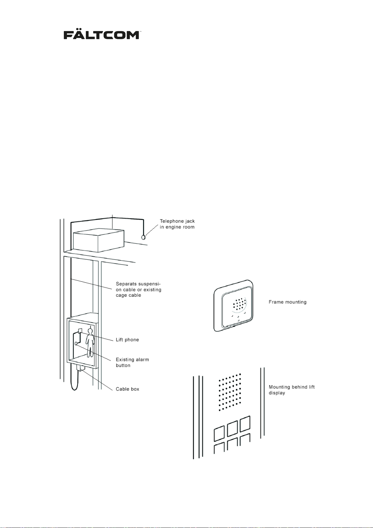
The lift phone can be mounted behind the car operating panel (COP), on the panel with a
small front plate and f ram e or with a l arger f ront pl ate and f ram e with an integrate d alar m button.
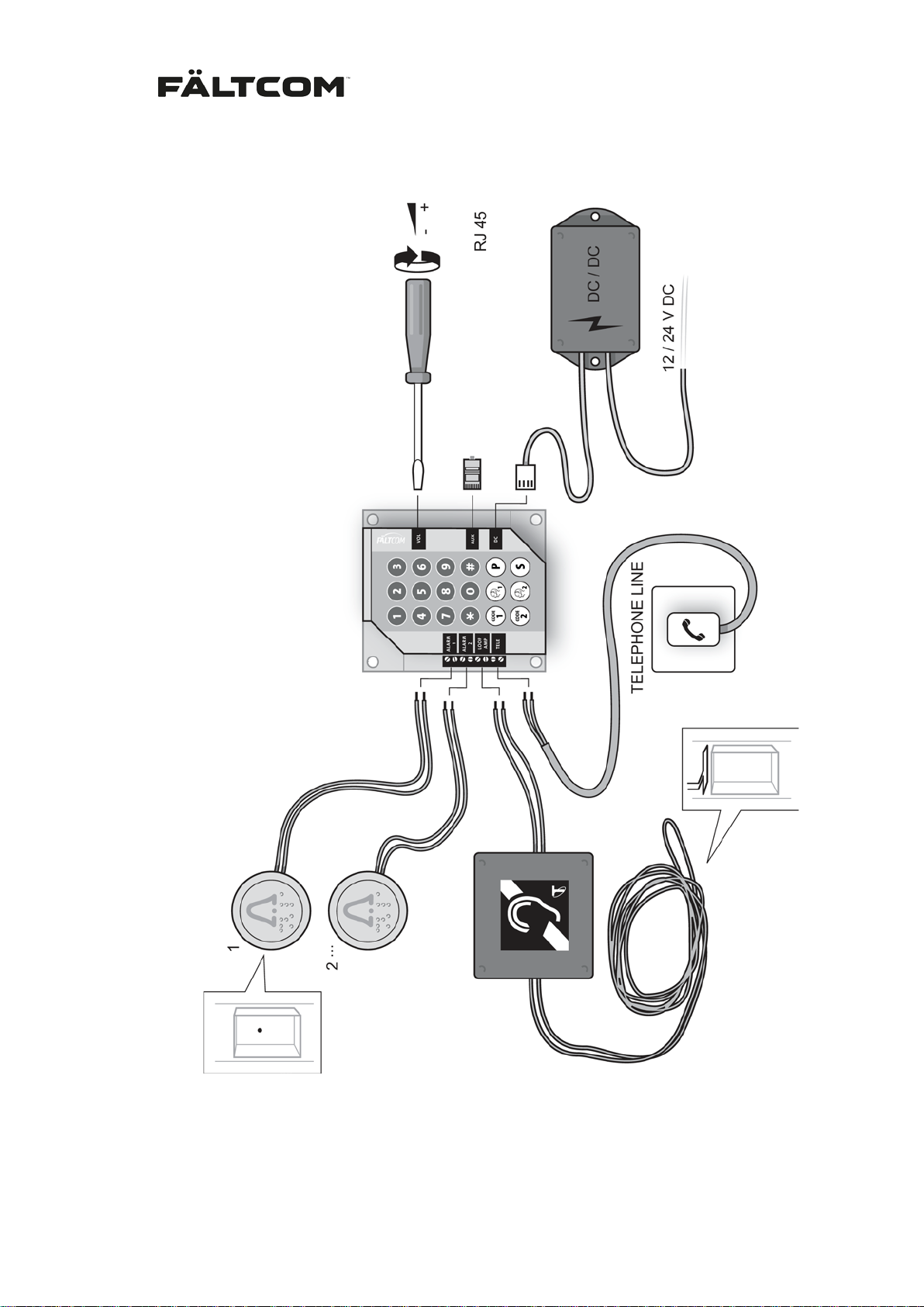
The connection of the lift p hone requ ires one two-wire cable to t he alarm button in the lif t and
one two-wire cable f or connecting a standard ana logue telephone line. It is possible t o use a
separate suspension c able of a round cable or f lat cable type. As an alter native two unused
wires in the existing car cable can be used. It is very important that the cable is fastened
properly. For the separ ate suspension cable there is a s pecial mounting kit, which includes
the necessary mounting parts.
Fält Communications 201 6 ©
162187 Manual Fältcom ECII® Flex V024D 2016-02-23 Page 6 of 41
Page 8

4.2 Multiple lift phone connection
The Fältcom ECII® F lex is des igned t o run o n the existing telepho ne l ine power supply. Separate power suppl y is only required if several lif t phones are connec ted to the s ame telepho ne
line or if the line voltage is below 25 VDC. See more under section Technical data.
Several lift phones may be connected to the same telephone line. When one of the lift phones
has established a c onnection, t he other ones will not be able to us e the line; a bus y tone will
instead be heard in the loudspeaker and the yellow LED will flash five times. W hen the line
becomes free, the alarm call will be connected automatically.
Every lift phone requires a uni que ID an d the def ault I D is 1. T he ID is us ed whe n call ing in to
the lift phone. The unit with ID 1 will answer the call and the others will listen in on the line and
only pick up the line if th at par ticular lift phone ID is c h os en. C onnect the lift phones in p aral le l
and place the lift p hone with ID 1 at the far e nd of the line. View secti on 6.13 for program ming.
Installation of two or m ore Fältcom ECII® Flex on the same telephone line requires a separate power supply to the lift phones . The lift phone o utlet mark ed DC is then conn ected to the
lift’s existing emergenc y power supply via a special DC/DC converter. If no power supply is
available a separate emergenc y power source with a bui lt-in batter y can be use d. Both products are described in the product catalogue.
A total of nine lift/em ergency phones m ay be connected using the sam e subscription. Check
with the local telep hone line operator how man y devices they support on the line. Ordinary
telephones, fax mac hines, m odems or other types of alar m transm itters m ust not be conn ected to the same telephone line because of the risk of disturbing the Fältcom ECII® Flex.
4.3 Programming and testing
On the back of the lift phon e, there is a keypad used f or programm ing call num bers, func tion
selection, and testing. A ll such settings are configured during th e installation procedure and,
normally, no subsequent c hanges are requ ired. It is also poss ible to remotel y program the lift
phone using a standard ph one or Windows-based software and a modem . Contact your local
distributor for more information.
The Fältcom ECII® Flex is capable of calling 6 alarm receivers or standard telephones with
tone selection.
The lift phone can be programmed to send a test alarm/routine call to a specific test
alarm/routine call receiver at intervals of 1 – 30 days. This alarm tests the lift phone electronics and the telephone line itself.
The lift phone can also be programmed to answer an incoming call automatically after one
call signal. In this case, tones are heard in the receiver when the call is connected.
If an emergency power supply is connected, the lift phone can automatically send an alarm if
the battery voltage is low and needs to be replaced. A special telephone number for the battery alarm can be programmed.
See section Programming for detailed programming instructions.
Fält Communications 201 6 ©
162187 Manual Fältcom ECII® Flex V024D 2016-02-23 Page 7 of 41
Page 9
5 Installation instructions
Only suitably qualified personne l ma y install the Fältcom ECII® Flex. Expertise, technical skill
and correct equipment are required to ensure safe and efficient installation.
Mind your own safety when installing Fältcom ECI I® Flex. You must never work in
an open lift shaft w ithout a safet y harness. Be ext remely caref ul and break cu rrent
if you work close to a voltage of 230-400V, e.g. in the lift motor room. Never disconnect a cable before you have made sure that it is not live.
Start by selecting a su itable plac e for the lif t phone. U sually you can find an eas ily accessible
and yet well protected place behind the lift panel. A void inst allin g the pho ne in a c orner or behind anything that m ay reflect the sound. Such installatio n might lead to acoustic feedback
instability between the loudspeak er and the m icrophone. You mus t be able to acc ess the existing suspension cab le and the alarm button in the lift. Also keep in m ind that you must be
able to access the back of the lift phone in order to connect cables and program different
functions. Norm ally this is easier to d o on the inside of the lift, befor e the lift phone is screwmounted.
Make sure that you will avoid sawing or drilling through existing cabling when you
make the holes!
5.1 Frame mounting
1. Mark and pre-drill the holes f or the lift phone frame according to the enclosed drill
template. Drill the holes f or the cables to the alarm button and telephone conn ection
according to the drill template.
2. Fasten the frame first and then the lift phone with the enclosed screws.
Note! Make sure the cable s have been connected an d the lift phone has been programmed.
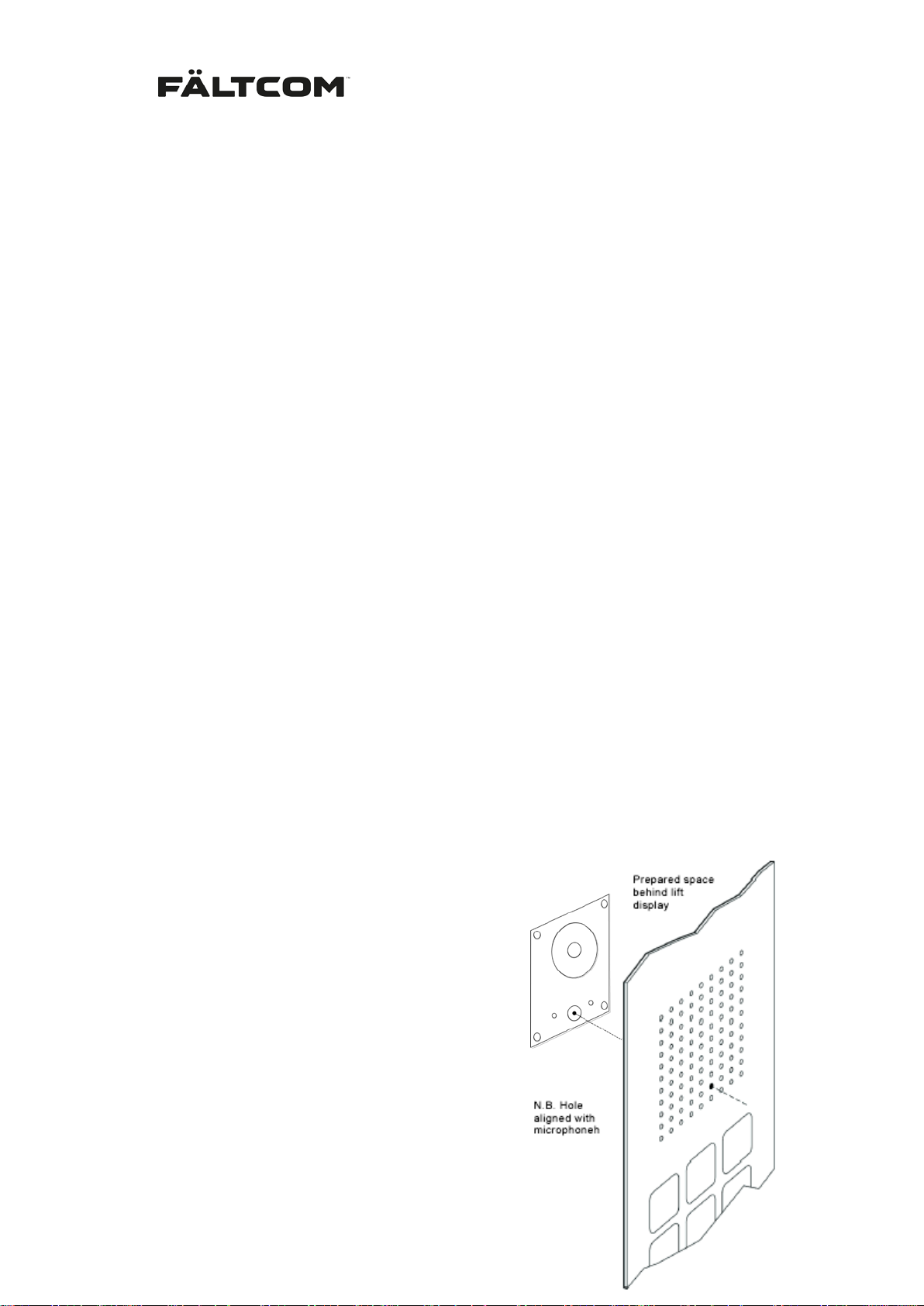
5.2 Mounting behind the car operating panel
This alternative is o nly possible if there is a lready
a prepared space for a lift phone behind the button & display plate. The Fältcom ECII® Flex version “COP” is specially designed for this type of
mounting. Since the design of the display may
vary, we are not able to give exact mounting instructions here.
Keep in mind that the microphone hole must
be aligned with a hole in the display plate. It
might become necessary to drill a new hole.
For the best sound qualit y the distance between
the lift phone front plate and the display plate
should not exceed 1 mm
Fält Communications 201 6 ©
162187 Manual Fältcom ECII® Flex V024D 2016-02-23 Page 8 of 41
Page 10

5.3 Connection to alarm button
1. Route a two-wire cable (max 10 m ) from the lift’s alarm button and connect the wires
to the lift phone’s terminal block at ”ALARM1” or “ALARM2”.
2. Fasten the cable with cable ties or cable clips on the outside of the lift.
Note that the alarm button in the lift car is norm ally double-breaking, i.e. m ade for two separate connections, one of them usually connect ed to a local alarm bell and the oth er one used
for the lift phone. The connections must have 1500V i s olat ion. If they are not, or i f the ex isting
alarm button only has one connection, the button must be replaced with another type.
Please note that the Fältcom ECII® Flex has a special version called “ALBU”, with an integrated alarm button whic h can be used if there is no s uitabl e alarm button availa ble in the lift.
That version has a double breaking alarm button where one part (NC) is used for the lift
phone and the other part (NO) can be used for the alarm bell.
5.3.1 Closing alarm button function
Note that the alar m button m ay have a closing or brea king f unction. Bre ak ing func tion is to be
preferred and is the defau lt setting in Fältcom ECII® Flex. If the butt on has closing function,
the lift phone m ust be programmed to hand le this. See sectio n Programming f or more information.
5.3.2 Separate alarm button(s)
If there is no alarm but ton in t he lif t car, a separate button must be installed. Note that i n order
to avoid misunderstandi ngs, there should never be two alarm buttons in a lift car. It is possible
to connect extra alarm buttons to the unit, for instance on top of the lift car where a repair man
can be trapped.
5.4 Connection to telephone line
The lift phone must be c onnected to a s tandard an alogue te lephone lin e. Norm ally it can also
be connected to an ISDN connec tion via a terminal adaptor. To minim ize disturbance when
more than one Fältcom EC II® Flex is conn ected to the sam e telephone line it is rec ommended that they are connected in parallel.
If the lift phone is connec te d to a s tan dar d te le pho ne jac k, the jack should be located in th e lif t
motor room or some other room with no admittance to unauthorized persons. This is important to ensure the connection is not interrupted by mistake.
5.4.1 Connection to telephone switches and other devices
The Fältcom ECII® Flex can be connected to a n extension in a telephone switch, provided
that the c onnection is ana logue. Digital switches usually have at least one analogue co nnection, since many alarms, faxes and m odems require analogue communication. When con-
necting to a telephone switch it must be verified that the switch also works in cas e of
power failure. The lift phone has a function, which enabl es it to dial a pr ef ix, e.g. ‘0’, and then
wait two seconds for the dialing tone before procee ding with the alarm num ber. See section
Programming for more information.
Fält Communications 201 6 ©
162187 Manual Fältcom ECII® Flex V024D 2016-02-23 Page 9 of 41
Page 11
In some installations the telephone li ne might have an automatic dial or aut omatic connection.
This means that the telephone line automatically dials or connects to a pre-programmed
number. By program m ing the Fältcom ECII® Flex with a pause the lift p hone accept s that the
telephone line manages to call up the pr e-programm ed number. Af terwards the lif t phone uses the telephone li ne for the intende d functions. For more inform ation read section Program-
ming.
By connecting the lift p hone to a GSM ada pter that sim ulates an analogue te lephone line t he
lift phone can easi ly send alarms via the GSM network. Contac t your distributor f or more information. For all alarm communication v ia the GSM network it is very important to es tablish
that the communication system still works in case of power failure.
The lift phone can also be c onnec te d to a VoIP system; in this cas e a converter to a ana log ue
line m ust be con nected bet ween the VoIP network an d the lift ph one. Som etimes adjustment
of the equipment is needed to m ake sur e that the length of the tones ( DTMF) to and f rom the
lift phone are not affected by the equipment. C ontact your distributor for m or e inf ormation. It is
very important to establish that the telephone line still works in case of power failure.
5.4.2 Connection with separate suspension cable
Normally, a separate sus pe nsion c ab le of a round cable or f lat cable type is used between th e
lift phone and the telephone jack. A separate suspension cable usually gives better sound
quality and less inter ference. The required length of c able and mounting kit can be ordered
with the lift phone.
Note that the cable brack ets included in the mounting kit must be used in order to guarantee
the function. The com bined wall and lift-car brack ets comprise bracket, screw, washer and
cable ties.
Check carefully that the cable will not be torn off, squeezed or chafed between the lift
car and shaft wall.
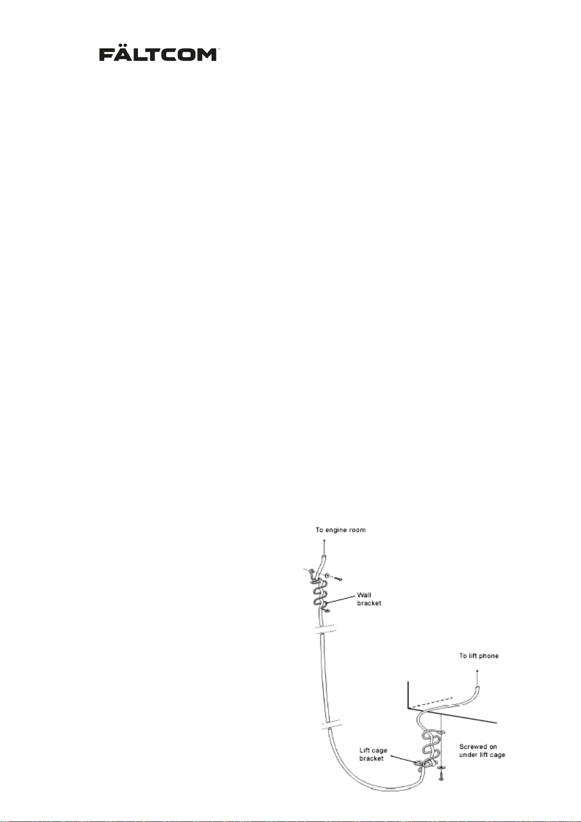
5.4.3 Flat cable type
1. Check that the cable is lo ng enough,
allowing a margin, to reach the telephone jack.
2. Fasten the cable securely until it
reaches the lift shaft wall.
3. Secure the cable with a wall bracket
according to the figure on this page.
4. Fasten the lift-car bracket under the
lift car with s crews, an d attac h the cable to the bracket. Alternatively, the
cable can be attached to a suitable
beam on the lift car ins tead of the liftcar bracket.
5. Route the cable to the lift phone and
Fält Communications 201 6 ©
162187 Manual Fältcom ECII® Flex V024D 2016-02-23 Page 10 of 41
Page 12

connect the wires to the terminals marked ”TELE”.
6. Fasten the cable with cable ties or cable clips on th e outside of the lift near the lif t
phone.
7. Connect the two centr al wires in the enclosed m odular connector to the sus pension
cable wire, and connect the modular connector to the telephone jack in the motor
room. Mark the connection so that it will not be removed by mistake.
5.4.4 Connection via existing cable
Warning! Ensure that you will not come into contact with any live power cables.
Normally, the existing lift cable (usually a big flat c onductor cable) goes to a car cable box,
where you may find un used wires (if any) that can be used for the lift phone. It is important
that the wires to be us ed are next to each other in the lift c able in order to mini mize disturbances. In the event of bad sound quality a separate cable must be used.
1. Connect a two-wire c able f rom the unused pair in the car cable box and draw the c able to the terminal strip marked ”TELE”.
2. Fasten t he cable with cable ties or cab le clips on the outside of the lif t near the lift
phone.
3. Connect the suspens ion c able wire to the t eleph one j ack in t he motor room . Mark the
connection so that it cannot be removed by mistake.
5.5 Connection of voltage supply
Note that separate voltage supply is on ly required if more than one lif t phone is to be connected to the same tele phone line, or if s ingle-mounted to a line voltage below 25 VDC, usually an internal telephone switch (PABX).
The voltage supply must com e from a source that wil l work even in case of a power failure,
e.g. the lift’s emergenc y lighting system, and the converter must have 1500V isolation from
ground; which is necessar y in order to avoid disturbi ng the telecom s tation. The voltage supply to the Fältcom ECII® F lex should be 5 VDC and must not exceed 7 VDC. If no existing
emergency power suppl y is available a se parate em ergency power source with a bui lt-in battery can be used. Contact your local distributor for more information.
1. Connect a two-wire cable to the exis ting suspension cable wire for emergenc y lighting. Measure to verify the correct voltage between the pins.
2. Connect the cable to the DC converter input.
3. Connect the DC converter to the lift phone outlet marked ”DC”.
4. Connect the DC converter on the outside of the lift and fasten the c able with cable
ties or cable clips.
Fält Communications 201 6 ©
162187 Manual Fältcom ECII® Flex V024D 2016-02-23 Page 11 of 41
Page 13

5.6 Connection to loop amplifier
To enable passengers with impaired hearing to communicate with the alarm centre a loop
amplifier can be connected to the Fältcom ECII® Flex. Contact your local distributor for information about approved loop amplifiers that can be used with Fältcom ECII® Flex.
Connect the output marked “LOOP AMP” to the loop amplifier. The loop amplifier must work
during power failure. Connect it to a power supply that is known to work during power failure.
5.7 Connection of external pictogr am
It is possible to connect ext ernal lamps to indicate alarm status on the lift phone accor ding to
EN81:70 using the system component Pictogram Driver. It consists of a DC-converter and
drive circuits for exter nal lam ps. It is c onnected to the output m ark ed “DC”, to 12V emergency
power and to the external lamps. Contact your distributor for more information.
5.8 Connection to Intercom (art. 2153)
For communication bet ween the machine ro om and the Fältcom ECII® Flex use the Fältcom
Intercom Unit (art. 215 3). Moun t the Intercom U nit in the m achine room and c onnec t the po wer, telephone line an d inter com handse t. Conn ect the Fältcom ECII® Flex in the lift car to the
Lift phone (ECII) output on the I ntercom Unit. Please vie w the Intercom installatio n instruction
for more information.
5.9 Connection to additional Alarm butt ons ALBU (art. 2142)
For additional alarm buttons on top and below the lift car us e the Fältcom (art. 2142). Mount
the ALBU on an appropriate location and connect it to th e “ALARM 2” input on the Fältcom
ECII® Flex. If using two Alarm Buttons they need to be connected in series; the A larm Buttons are always Normally Closed.
To activate the “ALARM 2” input for the Alarm Button, program:
5.10 Connection to Speech Unit (art. 2230)
For additional microphone and speaker on top and below the lift car use the Fältcom Flex
Speech Unit (art. 2230). M ount the Speech Unit on an appropriate locati on and connect it to
the Fältcom ECII® Flex AU X input us ing the Cat5 c able, use th e IN connec tor on the S peech
Unit. Please note that the cabl e m ust be ordered separately depen ding on the r equired length
of the cable. The alarm input on the Fältcom ECII® Flex is activate by default.
If using two Speech Units; connect the s econd Cat5 cable f rom the OUT connector of Sp eech
Unit 1 to the IN connector on Speech Unit 2. Also, move the jumper from SU1 to SU2 on
Speech Unit 2.
To speak to the Speech Unit first call in to the Fältcom ECII® Flex and establish a duplex
conversation. Then pres s key ‘3’ to acti vate the sound in the Speech Unit, press ‘3’ again to
switch the sound back to the Fältcom ECII® Flex.
Fält Communications 201 6 ©
162187 Manual Fältcom ECII® Flex V024D 2016-02-23 Page 12 of 41
Page 14
6 Programming
Programming of alar m numbers, al arm codes and various f unctions c an be affected by using
the keypad on the reverse of the Fältcom ECII® Flex, by calling the u nit usi ng a st andard telephone or by using suitable Windows-based software. This section describes programming
using the keypad and standard telephone. All programmed settings are stored in memory
even if the lift phone is disconnected from the telephone line.
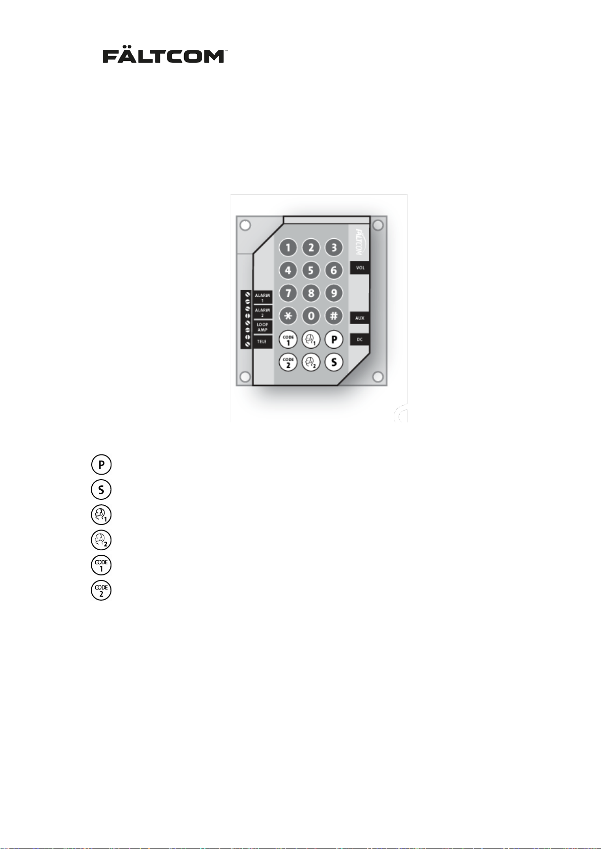
The keys on the keyboard have the following functions:
Programming – Starts and ends all programming sequences.
Sequence receiver – Used when programming more than 2 alarm receivers, receivers 3-6.
Alarm receiver 1 – Phone number to alarm receiver 1.
Alarm receiver 2 – Phone number to alarm receiver 2.
Alarm code 1 – Used for alarm receiver 1, 3, 4, 5 and 6.
Alarm code 2 – Used for alarm receiver 2.
The other keys have the same function as on a standard telephone.
6.1 Configuration settings
The Fältcom ECII® Flex can be pro gram med only after it has been s et t o pr ogr a m m ing m ode.
The telephone line m ust be supplied with c urrent for the k eys to be activated. Each time the
keys are pressed in programming mode a short ton e is heard and after each progr amming
sequence there is a 4-tone for successful and a 1-tone for unsuccessful programming.
In order for the emergency telephone to be progr ammed it has to be:
Fält Communications 201 6 ©
162187 Manual Fältcom ECII® Flex V024D 2016-02-23 Page 13 of 41
Page 15

1) Connected to the telephone line (analog line, not ISDN)
2) Connected to the alarm button (Normally Closed or Normally Open), and
3) Set the device in programming mode.
Programming can be initiated approximately 20 sec. after the telephone has bee n c onnected
to the telephone line. Upon completion of each programming sequence a 4-tone confirms that
the telephone has accepted the programming. If no button is pushed during a time lapse of 30
sec. programming mode is automatically deactivated.
Important! The telephone number of Alarm Receiver 1 must be programmed to make an
alarm. Alarm Code 1 is default ‘1’ but must b e programmed if the alarm is sent to an alarm
central.
6.2 Activation of programming mode
6.2.1 First time used of if unit is powerless
Remove the 8-pol connector and fasten the alarm button cords and telephone line cords.
Press down
into programming m ode. Once programming mode is enter ed this is confirmed by a tone i n
the loudspeaker . This can also be used it the Fältcom ECII® Flex in operati on; remove the
connector and wait 10 seconds for th e unit to loose a ll power. Press do wn
screw connector again.
and fasten the screw connector . The Fältcom ECII® Flex will automatica lly go
and fasten the
6.2.2 Reprogramming an Fältcom ECII® Flex
Press
for the alarm button, the default sett ing is 5 s econ ds . Once programming mode is entere d th is
is confirmed by a tone in the loudspeaker.
and the alarm button s imultaneousl y. Press for the s ame time as the selected tim e
6.2.3 Reprogramming from phone
Call the telephone number to which the Fältcom ECII® Flex is connected and wait for the device to answer. The Fältcom ECII® Flex will first answer with a modem tone and then switch
to a 3-tone message; please view section Calls to a lift phone for more information. Press
#<ID>, default is 1. Wait for the 3-tone message, then program the PIN CODE. Default code
is 1111.
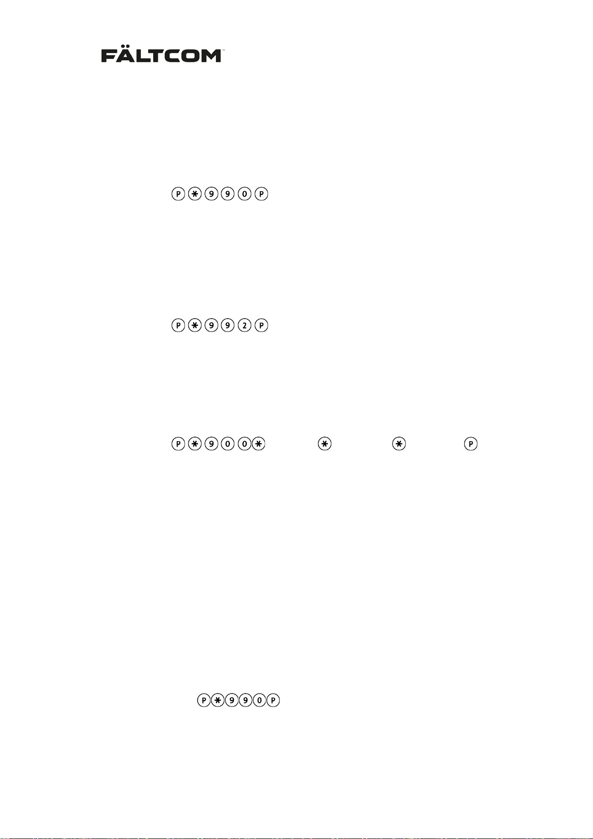
From phone:
# < PIN CODE> #
6.2.4 Indication and exit
The yellow and green LEDs will flash alternately when the Fältcom ECII® Flex is in program ming mode. Programming mode is deactivated automatically after 30 seconds if no key is
pressed. Note that som e exchanges (m ainly ISDN) so metimes disconnect the lif t phone after
a shorter time. All progr amm ing must then be done a t a differ ent location. Nor mal alarm s are
not affected by this.
You can also leave programming mode manually by pressing:
From keypad:
From phone:
Fält Communications 201 6 ©
162187 Manual Fältcom ECII® Flex V024D 2016-02-23 Page 14 of 41
000 #
Page 16
6.3 Reset to factory settings
This function will reset the Fältcom ECII® Flex to its default sett ings; clear ing all program m ed
receivers, codes and settings; all but Alarm Code 1 which is default set to ‘1’.
Note: Reset to default setting will not erase speech messages. See section about speech
messages for information on how to erase speech messages.
From keypad:
From phone:
990 #
6.4 Clear all active alarms
This function will c lear al l active a larms on the Flex. It will n ot remove receivers or codes , but
it will make the Flex stop c alling out an alarm , without an ack nowledgm ent of that alarm. Any
new alarm input made after this will be handled normally.
From keypad:
From phone:
992 #
6.5 Change of PIN code
For entering program ming mode remotely from a telephone a PIN code is ne eded. This is
default “1111”, but can be changed by the following:
From keypad:
From phone:
< old PIN> < new PIN > < new PIN>
900 < old PIN > < n ew PIN >
< new PIN > #
6.6 Alarm receivers and alarm codes
Six different alarm receivers can be programmed. Alarm receivers 1 and 2 have separate
alarm codes and rece ivers 3-6 use the alarm code f or receiver 1. If alarm receiver 2 is programmed, but not alarm code 2; receiver 2 will use alarm code 1 when dialing.
If the alarm receiver is a n alarm centre the centre wil l provide an alarm code. Program t he
alarm code to the corr ec t al arm receiver number. If the alarm receiver is a st andard telephone
or a mobile choose your own alarm code. There must always be a n alarm code program med
in order for the Fältcom ECII® Flex to call the receiver.
Note: Alarm Code 1 is default set to ‘1’.
1. If required, reset to factory settings:
From keypad:
From phone:
2. Enter phone number for Alarm Receiver 1:
Fält Communications 201 6 ©
162187 Manual Fältcom ECII® Flex V024D 2016-02-23 Page 15 of 41
990 #
Page 17
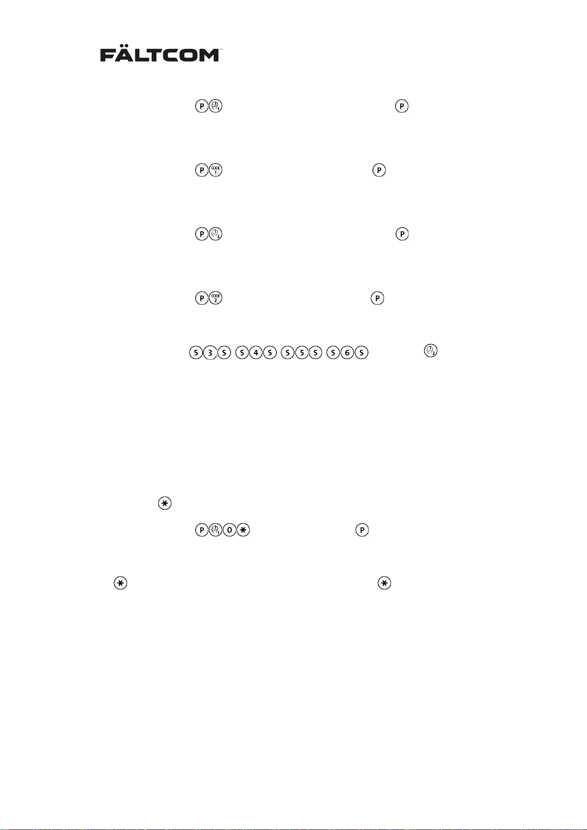
From keypad:
From phone:
3. Enter Alarm Code for Receiver 1:
From keypad:
From phone: 091 < Alarm Code 1 (max 10 digits) > #
4. Enter phone number for Alarm Receiver 2:
From keypad:
From phone: 002 < Telephone number (max 20 digits) > #
5. Enter Alarm Code for Receiver 2:
From keypad:
From phone:
For alarm receivers 3 to 6, use the keys:
From keypad:
above.
From phone:
001 < Telephone number (max 20 digits) > #
092 < Alarm Code 2 (max 10 digits) > #
< 003- 006 > < telephone number > #
< Telephone number (max 20 digits) >
< Alarm Code 1 (max 10 digits) >
< Telephone number (max 20 digits) >
< Alarm code 2 (max 10 digits) >
instead of
Note: Do not forget to test the setting by sending a test receiver alarm.
If a telephone number is missing, an error tone will be heard in the loudspeaker when
an alarm is activated and the LED’s on the front will flash alternately three times.
6.7 Prefix in a PABX switch board
under item 4
If the lift phone is connec ted to a PABX that requires a prefix to get an external extension;
program a star,
From keypad:
From phone:
Each will give a 2 second pause; for longer pause use several .
, after the prefix. E.g. if the prefix is 0 then progr am:
< Telephone number >
001 0 < Telephone number > #
6.8 Alarm input setting
All three alarm inputs of th e Fältcom ECII® F lex can be config ured. Alarm input 1 is designed
for the alarm button in the car and c an be configured to normally open or normally closed.
Alarm input 2 and 3 (serial interface labeled “AUX”) can be configured for normally
open/closed push butt on and also if the alarm shall be defined as an emergency alarm, tec hnical alarm or if the input signal shall be defined as a filtering signal for alarm input 1.
Examples of technica l alarms are sum alarms fr om the lift controller or sensors f rom the lift
car doors and more.
Fält Communications 201 6 ©
162187 Manual Fältcom ECII® Flex V024D 2016-02-23 Page 16 of 41
Page 18
Note: If the a larm input is c onnect ed to th e lif t control ler or other externa l dev ices the con nection must be separat ed using a relay connect ion, please view Appen dix for relay connecti on
drawing.
Setting of alarm input 1
Normally closed function is default. If the lift phone version with integrated alarm button is
used it is already connected to the lift phone a larm input. If the alarm button has normally
open function the lift phone must be programmed accordingly:
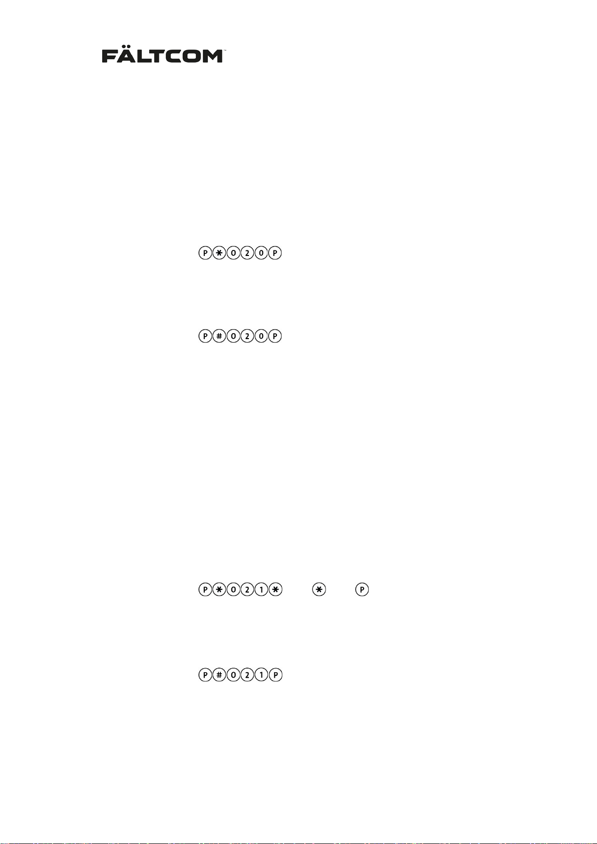
Set normally open alarm button:
From keypad:
From phone:
Reset to normally closed alarm button:
From keypad:
From phone:
Note: If alarm input 1 is filtered ther e is a 30 second override; m eaning if the alarm button is
pushed more then 30 seconds an emergency alarm will be s ent even though the filter signal
is active. This can also be used for accessing programming mode when using filtering.
020 #
# 020 #
Setting of alarm input 2
This input is of open/closed character a nd c a n be us ed f or a f ilteri ng s igna l, t echn i c al a larm or
a normal emergency alarm. It is configured as follows:
X is either 0 = Normally Open
1 = Normally Closed
Y is either 0 = Emergency alarm
1 = Technical alarm
2 = Filtering signal
Alarm input 2 is deactivated by default, function is activated by:
From keypad:
From phone:
021 < X > < Y > #
< X > < Y >
Function is deactivated with:
From keypad:
From phone:
# 021 #
Example: When alarm inpu t 2 is conf igured as a filter ing s ignal it wi ll af fec t the fu nction alit y of
alarm input 1 as follows: If alarm input 2 is configured as X = 0 => N/O and Y = 2 => Filtering
signal it will not be poss ible to initi ate an alarm from alarm input 1 as lon g as a open sig nal is
Fält Communications 201 6 ©
162187 Manual Fältcom ECII® Flex V024D 2016-02-23 Page 17 of 41
Page 19
obtained in alarm input 2. The push button in alarm input 1 is filtered. When the signal in
alarm input 2 changes to closed the a larm input 1 will be activated and alarm calls are poss ible. Pl ease note that there is a 30 second overr ide on the alarm input even though it is f iltered.
Setting of alarm input 3 (AUX)
This input is of o pen/ c los ed c harac ter a nd can be used for a f ilteri ng s i gna l, tec hn i cal a larm or
an emergency alarm. It is configured as follows:
X is either 0 = Normally Open
1 = Normally Closed
Y is either 0 = Emergency alarm
1 = Technical alarm
2 = Filtering signal
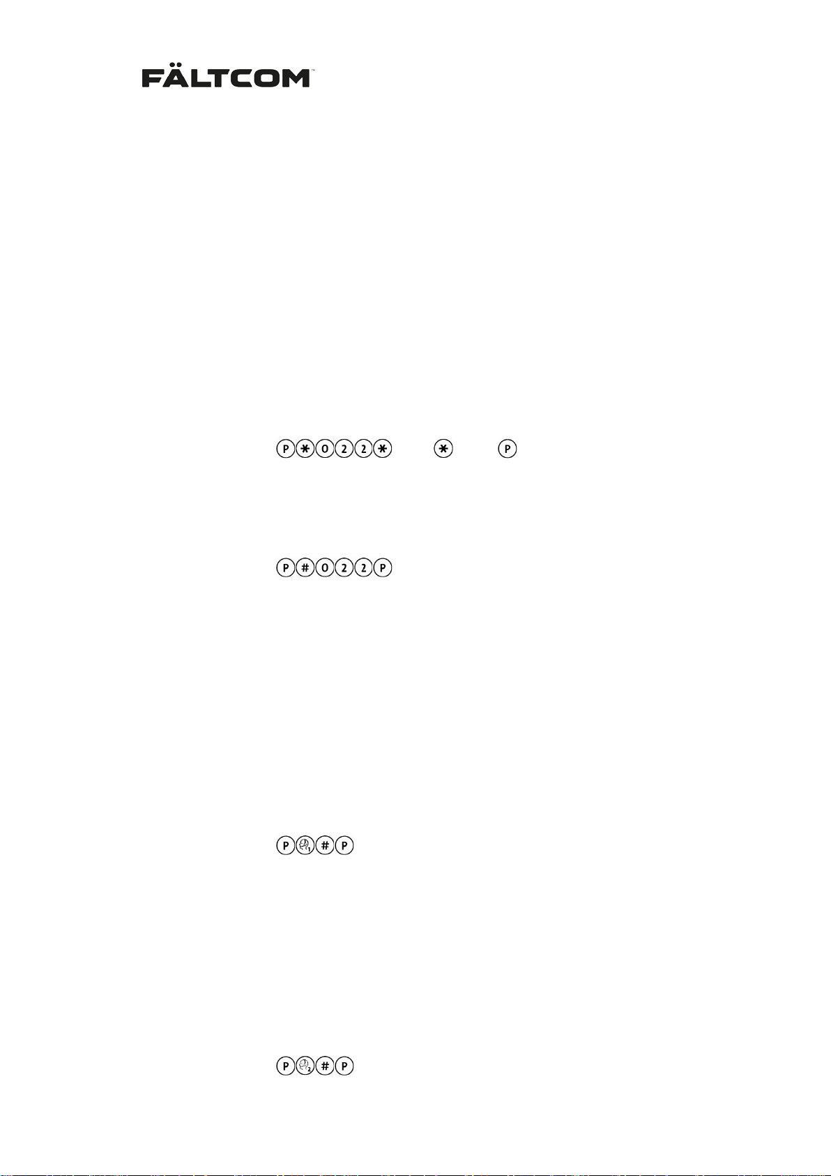
Alarm input 3 is activated as N/O emergency alarm by default, and can be changed by:
From keypad:
From phone:
Function is deactivated with:
From keypad:
From phone:
022 < X > < Y > #
# 022 #
< X > < Y >
Please view document Flex I/O description for information on what pins to use.
6.9 Test of alarm reception
After a finished installation Fältcom highly recommends testing the programmed alarm receivers.
Test of Alarm Receiver 1
When this sequence is programmed the Fältcom ECII® Flex calls Alarm Receiver 1 after
leaving programming mode.
From keypad:
It is also possible to leave programming mode manually and press
the alarm button in the lift car and check that the alarm reaches alarm
From phone:
receiver 1.
001 #
Test of Alarm Receiver 2
When this sequence is pr ogrammed the Fältcom ECII calls Alarm Receiver 2 after leaving
programming mode.
From keypad:
Fält Communications 201 6 ©
162187 Manual Fältcom ECII® Flex V024D 2016-02-23 Page 18 of 41
Page 20

From phone: 002 #
Test of Sequence Receivers (alarm receiver) 3-6
When this sequence is pr ogrammed the Fältcom ECII c alls Alarm Receiver 3-6 after leaving
programming mode.
From keypad:
From phone:
< -
00 < 3-6 > #
>
Priority order for test of receiver
When setting a test of alarm receiver the test will be queued inter nally in the Fältcom ECII®
Flex. When leaving progr amming m ode the Fältcom ECII® Flex will start the test of alarm receivers and call in the following priority order:
1. Alarm Receiver 1
2. Alarm Receiver 2
3. Sequence Receiver 3
4. Sequence Receiver 4
5. Sequence Receiver 5
6. Sequence Receiver 6
7. Test alarm/Routine call receiver
8. Technical alarm receiver
9. Information alarm receiver
6.10 Change of time delay for alarm button
The delay time on the alar m button c an b e s et to b etween 1 and 30 seconds. The default time
is 5 seconds.
From keypad:
From phone:
Note: The delay program med is the time until the alarm is activated by the Fältcom ECII®
Flex. It will tak e an additional tw o secon ds bef ore t he alarm is called o ut because of the startup time and latency in the PSTN.
053 < 1–30 > #
< 1-30 >
6.11 Connections to telephone line with automatic dial/ connection.
If the Fältcom ECII® Flex is connected t o a telephone line with automatic dial or automatic
connection; where the tel ep hone ex c hang e direc ts the call without the user enter in g an y ke ys,
a pause m ust be added to preve nt the Fältcom ECII® Flex from c alling out. One
represents a pause of two seconds. There is no need to program any telephone number since
the telephone exchange takes care of that.
From keypad:
From phone:
Fält Communications 201 6 ©
162187 Manual Fältcom ECII® Flex V024D 2016-02-23 Page 19 of 41
001 #
– symbol
Page 21
6.12 Automatic test alarm/routine call
This function calls a test alarm/routine call receiver to verify the connection between the Fältcom ECII® Flex and the alarm receiver. Automatic tes t alarm/routine call shall only be programmed if the lift phone is connected to an alarm central, the alarm central can verify that
the incoming test alarms/routine calls are correct. A test alarm/routine call is silent; no tones
are heard in the lift.
When the test alarm/routine call function is activated the first test alarm/routine call is sent 5
minutes after exiting programming mode and the following test alarm/routine call is sent 10
hours after the first. The third and following test alarm/routine call are sent every N x 24 hours
where N is the test alarm/routine call interval in days. Note that the automatic test counter is
reset every time an automatic test related parameter is changed and when the power is disconnected from the lift phone. If the lift phone has been out of power and the power returns it
will send the next test alarm/routine call after 10 hours.
If a test alarm/ routine call fails the next attem pt is made after 10 m inutes . In total 10 attem pts
are made. If a test alarm /routine call is recei ved for ins tance in the third attempt t he next test
alarm/routine call will be sent N x 24 hours after the last attempt. This means that the lift
phone autom aticall y distributes t he test alar ms /routine calls to a time when th e telephone line
of the alarm receiver is normally available.
It is also possible to m ake the Fältcom ECII® Flex call out an additional test alarm/routi ne call
after each main alarm. To do this, use alternative 1b instead of 1a.
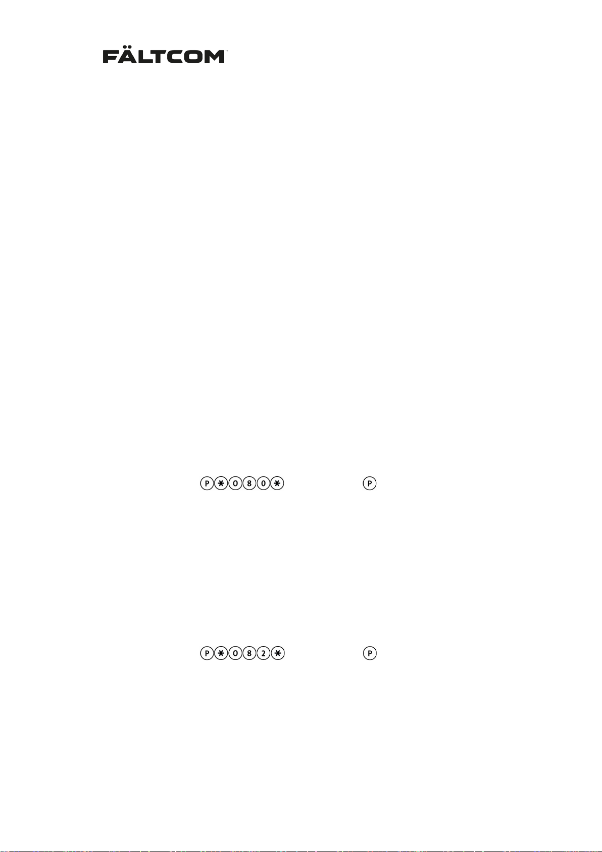
Activation of test alarm/routine call
1 a. Select the required test interval: 1 to 30 days. (Use a number between 1 and 30.)
From keypad:
From phone:
If the test alarm/routine call should go to the same receiver as AR1 an d us e th e same
code; no more pro gramming is neede d. If it will go to an individual num ber, continue
to paragraph 2.
080 < 1 – 30 > #
<Days (1 – 30)>
Activation of test alarm/routine call after main alarm
1 b. Select the required test interval: 1 to 30 days. (Use a number between 1 and 30.)
From keypad:
From phone:
082 < 1 – 30 > #
<Days (1 – 30)>
If the test alarm/routine call should go to the same receiver as AR1 an d us e th e same
code; no more pro gramming is neede d. If it will go to an individual num ber, continue
to paragraph 2.
Fält Communications 201 6 ©
162187 Manual Fältcom ECII® Flex V024D 2016-02-23 Page 20 of 41
Page 22
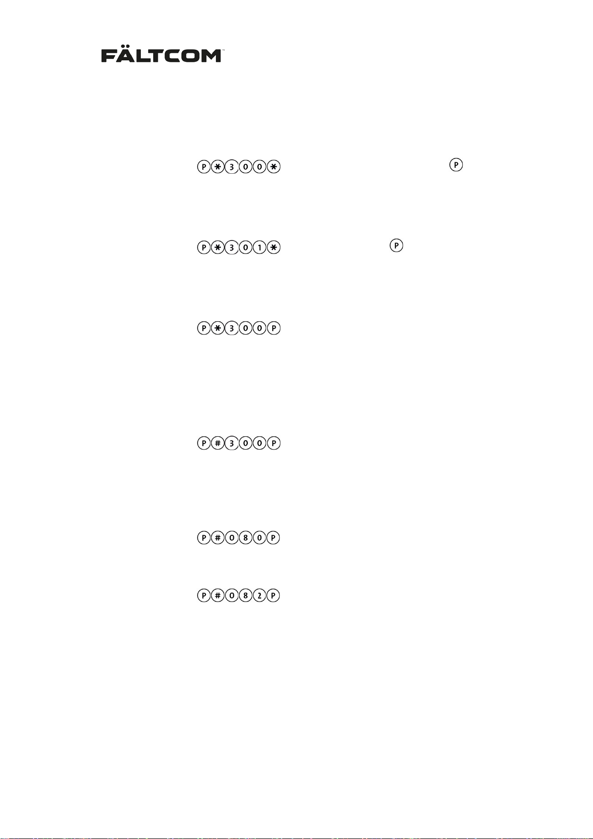
Number for separate test alarm/routine call receiver
2.
Enter the telephone number of the test alarm/routine call receiver:
From keypad:
From phone:
3. Enter alarm code for the test alarm/routine call:
From keypad:
From phone:
4.
Please view section 6.9 for priority order on test of receiver.
To delete the test alarm/routine call receiver, test alarm/routine call interval and test
alarm/routine call code:
To verify the test alarm/routine call function:
From keypad:
From phone:
From keypad:
300 < telephone number > #
301 < Code (max 10 digits) > #
300 #
<Telephone number (max 20 digits)>
<Code (max 10 digits)>
From phone:
To disable test alarms/routine calls (leaves alarm receiver and code intact, but no test
alarms/routine calls will be made until a new interval is programmed):
1 a. From keypad:
From phone:
1 b. From keypad:
From phone:
# 300 #
# 080 #
# 082 #
6.13 Incoming calls
It is possible to call the lift phon e and talk to the trapped per son. If there is onl y one Fältcom
ECII® Flex on the line the unit can be set to answer im mediately without selecting unit ID;
please see section Single unit. If ther e are multiple u nits sharing the li ne each unit requ ire a
unique ID; ID 1 is the defau lt setti ng but c an be chang ed, the Fältcom ECII® Flex can also be
blocked from receiving speech calls:
Fält Communications 201 6 ©
162187 Manual Fältcom ECII® Flex V024D 2016-02-23 Page 21 of 41
Page 23
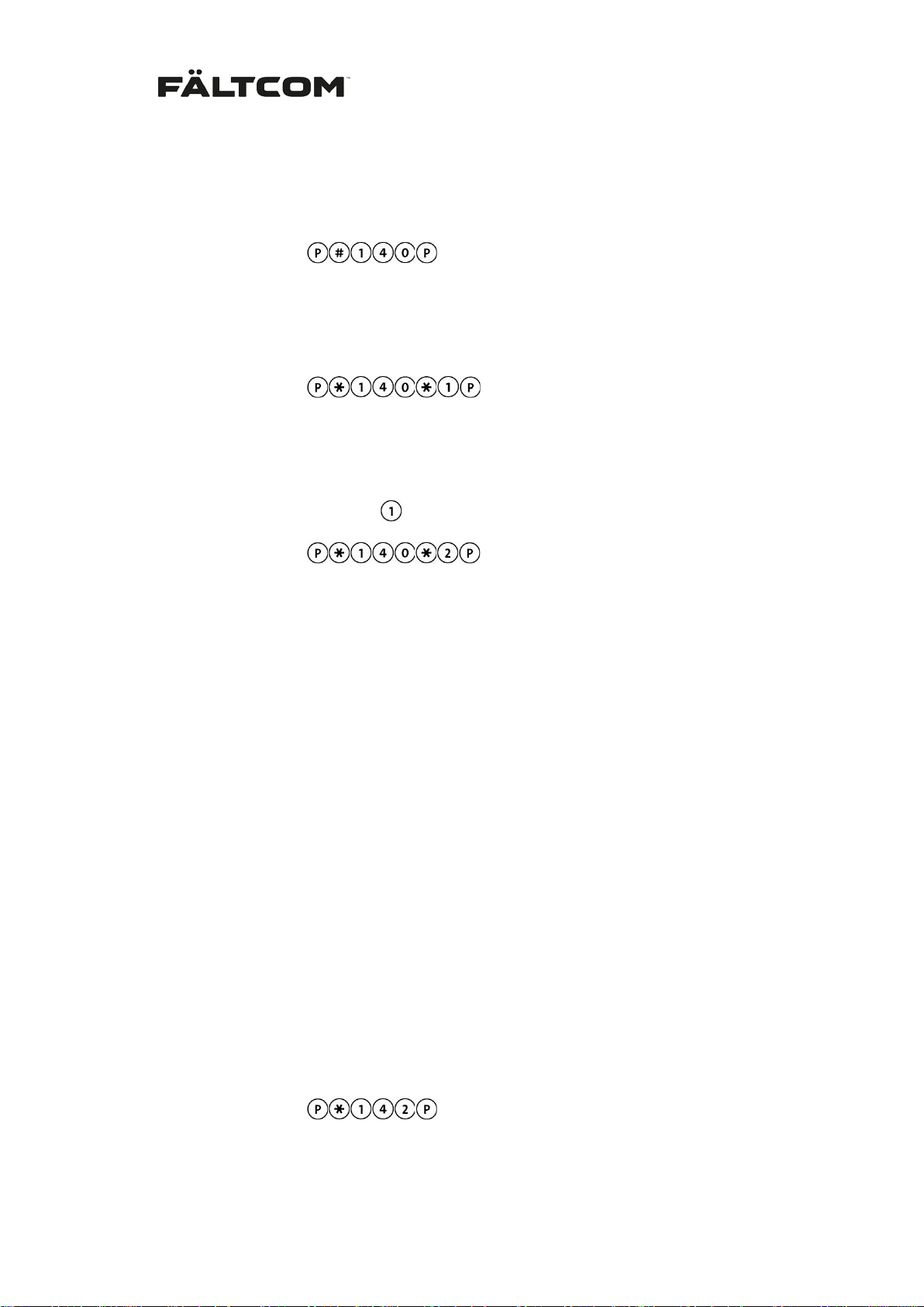
6.13.1 Multiple units on the line
1. For blocking the Fältcom ECII® Flex from incoming speech calls:
From keypad:
From phone:
2. For activation and allowance of incoming calls:
From keypad:
From phone:
With two or more Fältcom ECII® Flex connections on the same telephone line, one of them is
programmed as the master with ID number ‘1’. The others are coded with their individual
number (2-9) by replacing the digit
From keypad:
From phone:
It’s important that there is a lways one unit with ID number ‘1’. T he unit with ID num ber ‘1’ will
pick-up the phone and answer the incoming call.
For best sound qu alit y all lif t phones should b e con nec ted in para llel . The las t lift phon e in the
series is given identity ‘1’.
# 140 #
140 < 1 – 9 > #
140 2 #
with the corresponding digit. Example:
for lift phone 2 in the chain.
There can be nine l ift/emergency ph ones connected on the sam e line. But the te lephone exchange can have a limitati on on how many devices are supported on one line; contac t your
local operator for information on how many devices they support on one line.
See also section Ca lls to a lift phone f or more information on how to cal l in to the Fältcom
ECII® Flex.
Note: It is always pos sible to call the Fältcom ECII® Flex and pr ogram it even though it is
blocked for incoming speech calls. T o prevent the Fältcom ECII® Flex from answering a call
change the number of ringing signals before the unit answers to 30, see section 6.14 below.
6.13.2 Single unit on the line
If the Fältcom ECII® Flex does not share the line with an y other equ ipment the unit can be set
to answer the call without requirin g the selection of the ID; i.e. #1 or #2 and s o on. See section Calls to a lift phone for further information on call procedure. To activate this function:
From keypad:
From phone:
142 #
Fält Communications 201 6 ©
162187 Manual Fältcom ECII® Flex V024D 2016-02-23 Page 22 of 41
Page 24
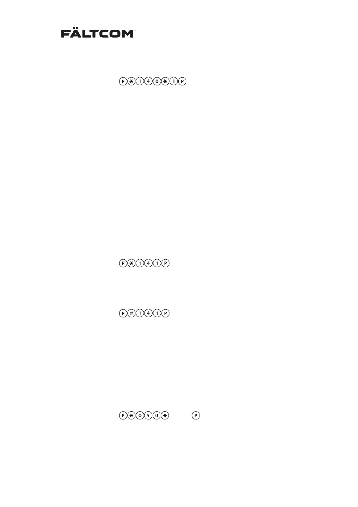
To go back to default settings program:
From keypad:
From phone:
140 < 1 > #
6.13.3 Active alarm mode
This alarm mode opens the Fältcom ECII® Flex for incoming calls for 6 hours after an alarm
call has been triggered. After this time the lift phone will be closed for incoming calls until a
new alarm is triggered.
To activate the Active alarm mode the following conditions must be fulfilled:
• Active alarm mode function is programmed
• A lift alarm has been called out
The active alarm mode is closed by pressing 5 on the receiving telephone or from the phone
that has called to the Fältcom ECII® Flex.
Alarm mode function is activated with:
From keypad:
From phone: 141 #
Alarm mode function is deactivated with:
From keypad:
From phone: # 141 #
The active alarm mode is automatically disconnected after 6 hours, but will be extended with
6 hours if a new speech connecting alarm is made or if a call is made to the Fältcom ECII®
Flex during this interval.
6.14 Answering time for incoming calls
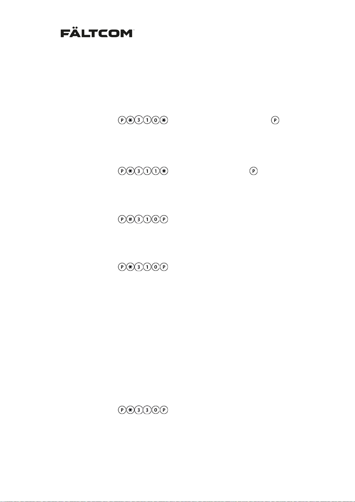
The number of ringing s ignals before th e Fältcom ECII® Flex ans wers incoming c alls can be
changed. Default is 1 ringing signal and can be changed up to 30. This is changed by:
From keypad:
From phone:
< 1-30 >
050 < 1-30 >
Note: Older Fältcom lift phone models have an answer tim e of ‘4’ ringing signals before answering. If a Fältcom ECII® Flex is sharing the line with older lift phone th e ringing sign al an-
Fält Communications 201 6 ©
162187 Manual Fältcom ECII® Flex V024D 2016-02-23 Page 23 of 41
Page 25
swer time must be changed to ‘4’ on the Fältcom ECII® Flex as well .
6.15 Technical & Battery alarm receiver
It is possible to send all technic al alarm s from alarm input 2 a nd 3 and also batt ery alarm s to
a dedicated alarm receiver. This is activated by:
From keypad:
From phone:
Enter Alarm code:
From keypad:
From phone:
Deactivate function:
From keypad:
From phone:
Test of the alarm receiver:
From keypad:
From phone:
310 < telephone number > #
311 < Alarm code (max 10 digits) > #
# 310 #
310 #
<Telephone number (max 20 digits)>
<Alarm code (max 10 digits)>
After exiting the programming mode, the phone will make a technical alarm call.
6.15.1 Battery alarm from Pow er Supply (art. 2001)
Battery back-up power is available using the Power Supply unit (art. 2001). The Power Supply
will generate a batter y alarm when the batter y power is low. The lift phone wil l send the battery alarm to the receiver using alarm type 17d (CPC protocol specific ). When the Fältcom
ECII® Flex s ends a batt ery alarm ; change the batt ery in th e Power Supp ly and p ush the “Reset” button. The lift phone will the n s end a battery reset alarm us ing alarm type 12d (CPC protocol specific). Battery alarm is default deactivated in the Fältcom ECII® Flex.
Activate battery and battery reset alarms from Power Suppl y:
From keypad:
From phone:
To return to default setting, disabling battery and battery reset alarms:
Fält Communications 201 6 ©
162187 Manual Fältcom ECII® Flex V024D 2016-02-23 Page 24 of 41
330 #
Page 26
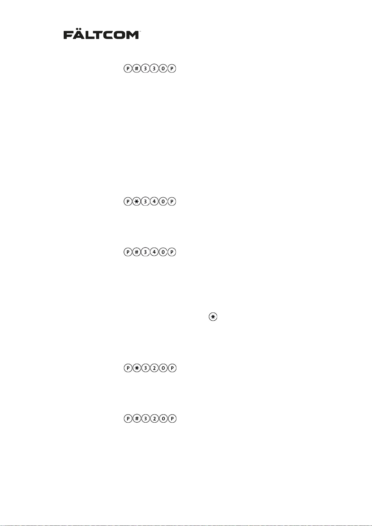
From keypad:
From phone:
# 330 #
6.15.2 Battery alarm from a GSM Gateway (art. 2236)
Similar to 6.15 .1 above the GSM Gate way (art. 2236) has battery back-up power incase of
power failure in the building. When a battery alarm is generated i n the GSM Gateway it will
change the dial ton e for the Fältcom ECII® Flex to detect. Please view the G SM Gateway
manual for specific ations. W hen the battery is replaced the Fältcom ECII® Flex will send a
battery reset alarm after the new battery has been tested, the same alarm types will be used
for battery and batter y reset alarm s as above. Battery alarm is def ault deactivate d in the Fältcom ECII® Flex.
Activate battery and battery reset alarms from GSM Gateway:
From keypad:
From phone:
To return to default setting, disabling battery and battery reset alarms from GSM Gateway:
From keypad:
340 #
From phone:
# 340 #
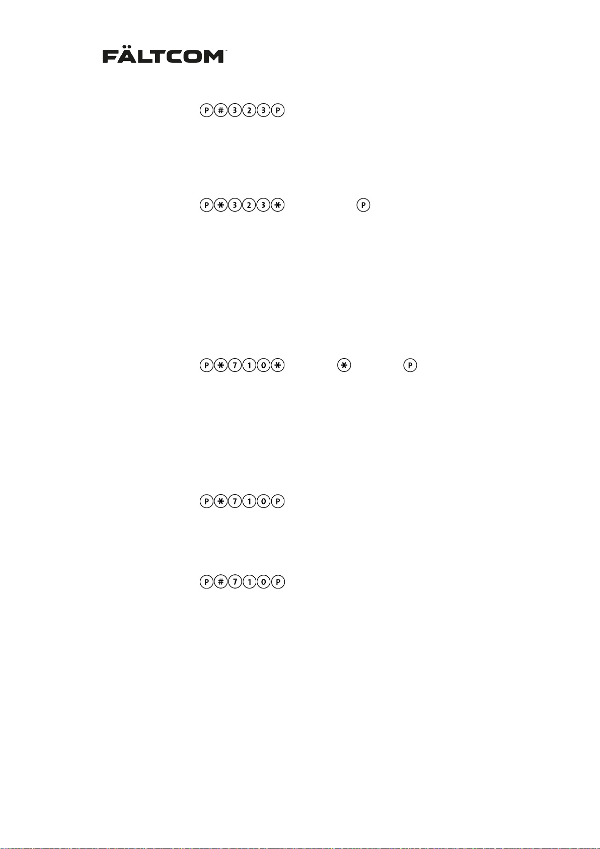
6.16 Simplified acknowledgement
Using this function it is possible to simplify the alarm reception procedure when using a
standard telephone as an alarm receiver. W hen the func tion is active , all numer ic buttons (0-
9) on the phone will ack nowledge the alarm and the
Each time an y of the buttons 0-9 is press ed on the telepho ne the discon nect time-out is reset
to 180 seconds. Only duplex mode is available.
The function is activated with:
From keypad:
From phone:
Return to default acknowledgment:
From keypad:
From phone:
320 #
# 320 #
button disconnects the alarm call.
Note: If a speech message is used; press any key to stop the message.
Fält Communications 201 6 ©
162187 Manual Fältcom ECII® Flex V024D 2016-02-23 Page 25 of 41
Page 27

6.17 321 – Disconnection of acknowledgement
It is possible to completely disconnect the acknowledgement f unction. This means that the
Fältcom ECII® Fl ex will make only one attempt t o reach the Alarm Receiv er 1. No further
calls will be made, reg ardless of result, until the alarm button is pushed again. Each
time any of the butto ns 0-9 is pressed on the teleph one the disconnect time-out is res et to
180 seconds. Only duplex mode is available.
To disconnect the cal l simply hang up or pres s the
the call is term inated by hanging up the p hone the Fältcom ECII® Flex may stay connected
on the line for up to 3 minutes from the start of the call. E.g. if the conversation las ted for 1
minute the Fältcom ECII® Flex may stay connected for an additional 2 minutes.
The function is activated with:
From keypad:
From phone:
Return to default acknowledgment:
From keypad:
From phone:
Note: If a speech message is used; press any key to stop the message.
321 #
# 321 #
button to disconnect the al arm call. If
6.18 323 – Acknowledge on end
When the Fältcom ECI I® Flex calls out an alarm duplex convers ation is automatically connected. But if ther e is no answer and no tone (0-9) received the Fältcom ECII® Flex wil l disconnect and call next alarm receiver. If Alarm receiver 1 is bus y, does not answer or an answering machine ans wers the call the Fältcom ECII® Flex will call Alarm Receiver 2 and so
on. Each time an y of the tones (0-9) is pressed by the receiver the dis connect tim e-out is reset to 180 seconds. Only duplex mode is available.
In order to ackno wledge that th e call has been rece ived b y an authori zed person the receiv er
must either press a tone during the convers ation (0-9) or use the
alarm call. The
other brands of emergency phones that require a different disconnect command.
The function is activated with:
From keypad:
From phone:
Return to default acknowledgment:
can be changed to an y tone for disconnect ing the c all, use this if there ar e
323 #
Fält Communications 201 6 ©
162187 Manual Fältcom ECII® Flex V024D 2016-02-23 Page 26 of 41
button to disconnect the
Page 28
From keypad:
From phone:
Changing the disconnect command tone is made by:
From keypad:
From phone:
Note: If a speech message is used; press any key to stop the message.
# 323 #
<0-9, , # >
323 < 0-9, , # > #
6.19 Detection of busy alarm receiver
Detection of busy tone is default acti vated. The Fältcom ECII® Flex will detect bu sy tone and
pause between 100 – 800 ms. Should the tone and pause le ngth be diff erent then the default
setting this can be adjusted by programming.
From keypad:
where XXXX is tone and YYYY is pause. Steps in milliseconds 800-2500.
From phone:
710 < XXXX > < YYYY > #
<XXXX> <YYYY>
where XXXX is tone and YYYY is pause. Steps in milliseconds 800-2500.
Activating the function and returning to default settings is made with:
From keypad:
From phone:
The function is disconnected and return to default setting is made with:
From keypad:
From phone:
710 #
# 710 #
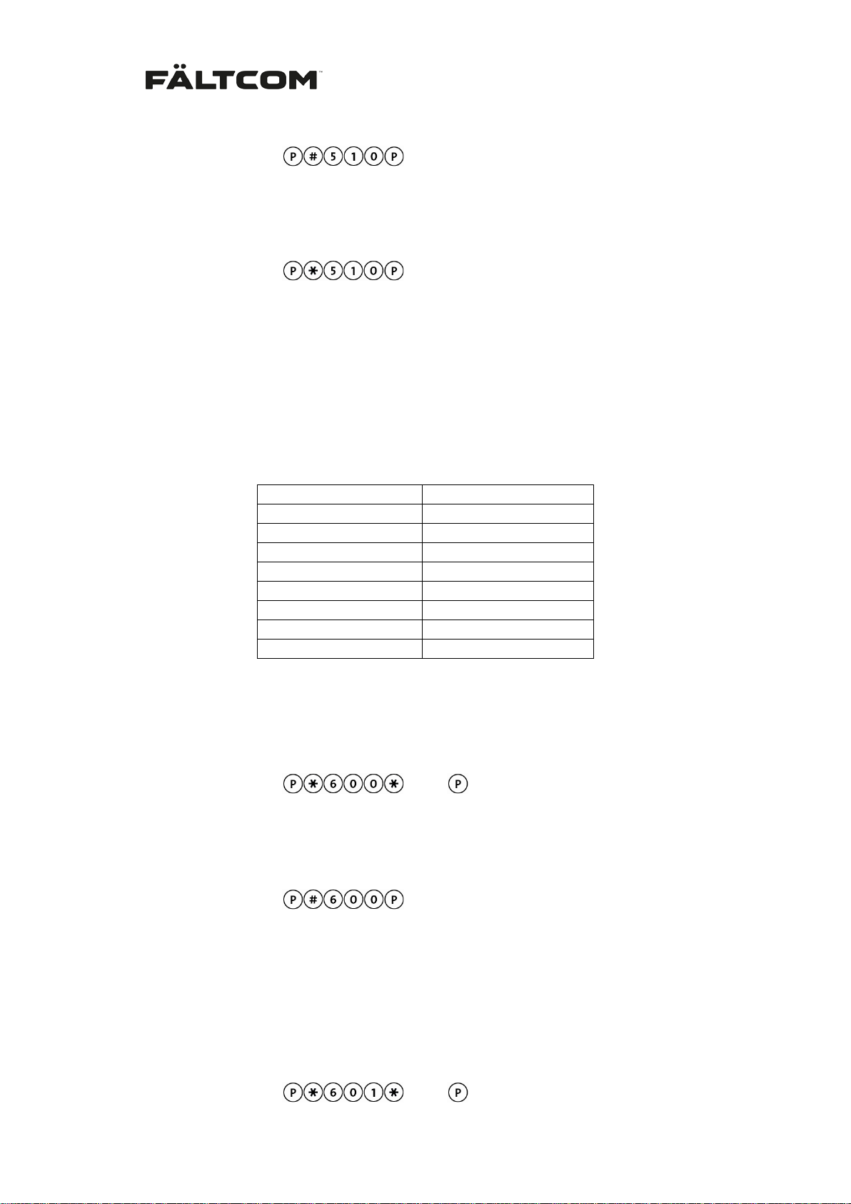
6.20 LED flashing sequence
When the alarm button has been activated and an alarm is registered by the lift phone, the left
LED on the Fältcom ECII® Flex is lit up in yellow. When the alarm is acknowledged the right
LED is lit up in green and the yellow LED is turned off. This flashing sequence, together with
the front pictograms complies with EN81:70.
There is an option to change to a flashing sequence which indicates a registered alarm with
flashing green light and acknowledged alarm with fixed green light, similar to earlier Fältcom
lift phones. This is done using the following programming sequence:
Fält Communications 201 6 ©
162187 Manual Fältcom ECII® Flex V024D 2016-02-23 Page 27 of 41
Page 29
Alarm input
Alarm type (decimal)
Input 1
10
Input 2
10
Input 3
10
Test alarm/routine call
26
Battery alarm
17
Battery reset alarm
12
End-of-alarm (magnet)
28
Info alarm
89
From keypad:
From phone:
Return to the yellow/green flashing sequence by programming:
From keypad:
From phone:
# 510 #
510 #
6.21 Programm able alarm types
When sending an a larm to an alar m receiver using the CPC protocol th e alarm will be identified by the alarm code and alarm t ype. The alarm code specifies the location of the device
and the alarm type specifie s the type of alarm that is being s ent. The alarm s can be of different types but they all have the same alarm code. For the Fältcom ECII® Flex the default
alarm types are:
Programmable alarm type alarm input 1
The normal alarm t ype 10 (0Ah) f or em ergenc y alarm s ma y be mapped t o anothe r alarm t ype
where XX represents an alarm type between 00 and 99. The alarm type is changed with the
sequence:
<XX>
From keypad:
From phone:
To reset the alarm type to the default value, enter:
From keypad:
From phone:
600 <xx> #
# 600 #
Programmable alarm type alarm input 2
Same functionality as for alarm input 1. Changed by:
From keypad:
Fält Communications 201 6 ©
162187 Manual Fältcom ECII® Flex V024D 2016-02-23 Page 28 of 41
<XX>
Page 30
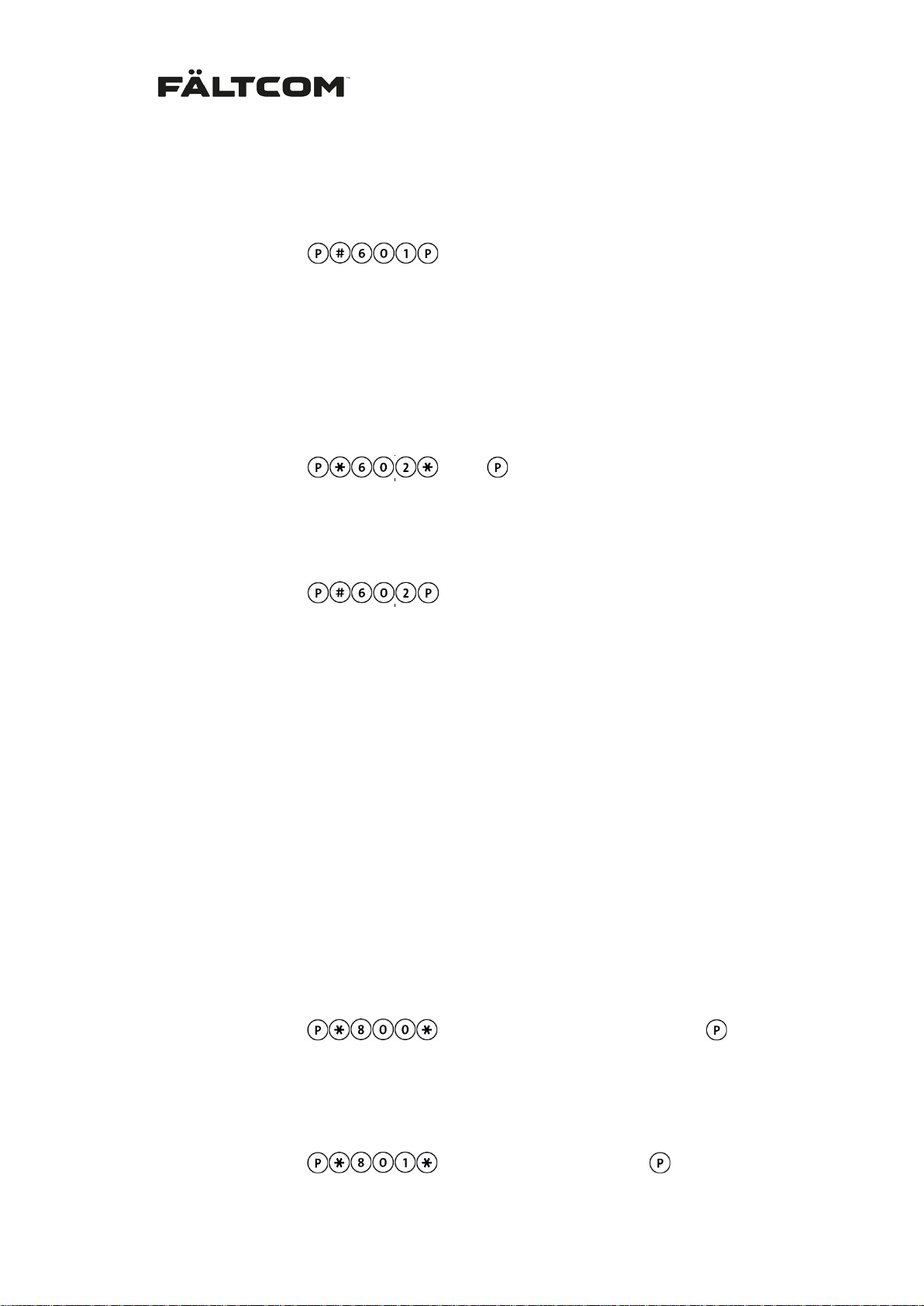
From phone: 601 <xx> #
To reset the alarm type to the default value, enter:
From keypad:
From phone:
# 601 #
Programmable alarm type alarm input 3
Same functionality as for alarm input 1. Changed by:
From keypad:
From phone:
602 <xx> #
To reset the alarm type to the default value, enter:
From keypad:
From phone:
# 602 #
Note that Fältcom ECII® Flex always assumes that the programmed alarm type is
speech-connecting by default, see section Alarm input setting for setting technical si-
lent alarms.
<XX>
6.22 Info Alarm – logging of alarms
Info Alarm will send a silen t alarm after an em ergency alarm using the alarm type 89d (59h).
This alarm can be used to access a log in an alarm receiver if the lift call has be en sent to a
regular telephone. T he Info alarm will use the s pecified Inf o Alarm code or if not pr ogrammed
it will use the Alarm Code 1, then add the alarm type of the alarm input, e.g.:
Lift alarm call to num ber 123 456 using alarm code 789 and alarm type 10. The Info alarm
receiver is programm ed to call 65 4 3 21 but n o c ode. A f ter the lif t alarm the Info alarm will then
call receiver 654 321 using alarm code 78910 and alarm type 89.
The Info Alarm is activated by programming:
From keypad:
From phone:
Enter Alarm code:
From keypad:
800 < Telephone number > #
<Telephone number (max 20 digits)>
<Alarm code (max 10 digits)>
Fält Communications 201 6 ©
162187 Manual Fältcom ECII® Flex V024D 2016-02-23 Page 29 of 41
Page 31
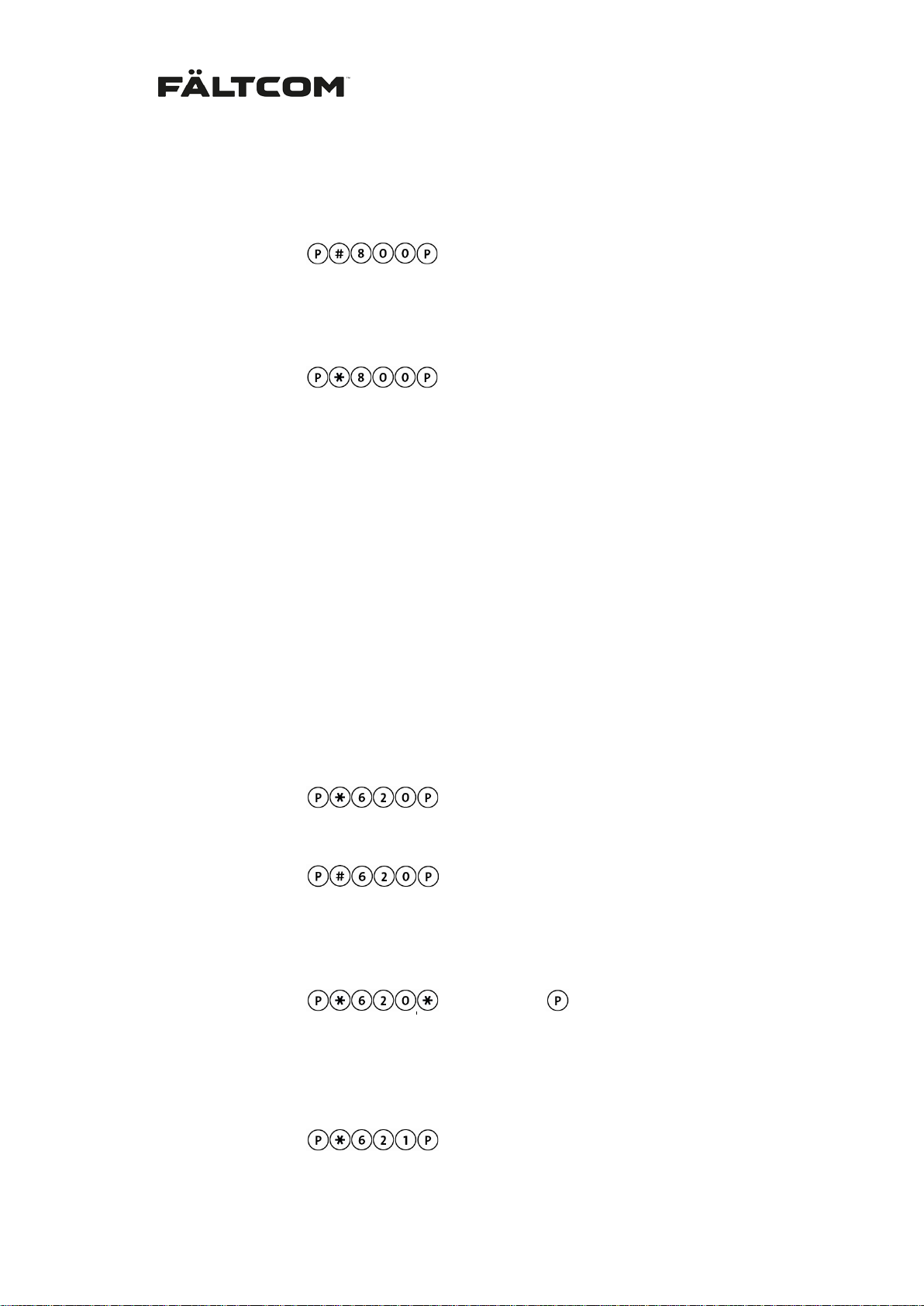
From phone: 801 < Alarm code (max 10 digits) > #
For deactivation of function:
From keypad:
From phone:
# 800 #
For test of the alarm receiver program:
From keypad:
From phone:
800 #
Observe that if the m ain alarm was ne ver acknowledg ed, no Info A larm will be se nt out. Also,
this function will not dial out an Info Alarm following battery alarms nor test alarms/routine
calls or end-of-alarm.
6.23 End-of-alarm
To ensure that a tr apped passenger is actually re leased from the lift ther e is a function which
sends an end-of-alarm c all with a spec ific alarm type to the a larm receiver. Alar m type is default 28.
This alarm is activate d b y the resc ue service by pressi ng a m agnet to the f ront of the Fältcom
ECII® Flex after ha ving released the trapped person. See drawing below f or location of the
magnetic switch. This is default deactivated. For activation or changing then alarm type:
For activation of magnetic switch:
From keypad:
From phone:
620 #
From keypad:
From phone: # 620 #
For activation of magnetic switch and setting a different alarm type:
From keypad:
From phone: 620 < alarm type > #
It is also possible to specif y that the magnetic switch s hou ld only be active for 6 hours af ter an
emergency alarm. This function is activated using:
From keypad:
From phone: 621 #
< alarm type >
Fält Communications 201 6 ©
162187 Manual Fältcom ECII® Flex V024D 2016-02-23 Page 30 of 41
Page 32
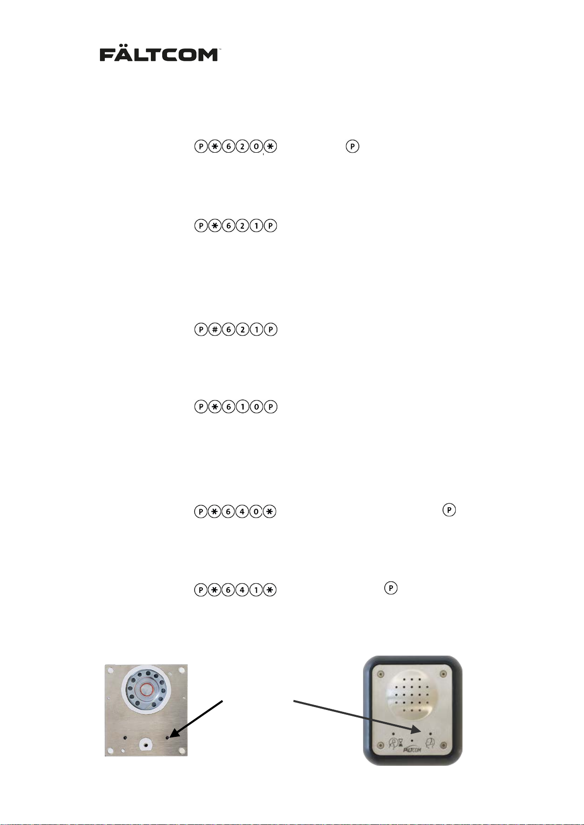
Position of magnet switch
The 6 hour open magnetic s witch will use the default alarm type specified f or the magnetic
switch function. To program another alarm type for the 6 hour open magnetic switch, first use:
From keypad:
From phone:
< alarm type >
620 < alarm type > #
Then activate the 6 hour open magnetic switch by programming:
From keypad:
From phone:
621 #
The 6 hour open magnetic switch can be deactivated and alarm type reset, the magnetic
switch will be turned off, use:
From keypad:
From phone:
# 621 #
It is also possible to s end an end-of-alarm using the keypad or a te lephone. The call will b e
made after leaving programming mode. The alarm can be sent using:
From keypad:
From phone:
610 #
6.23.1 End-of-alarm receiver
End-of-alarms c an be sent to a separate alarm rec eiver different from alarm receiver 1. If no
specific alarm rec eiver is pr ogramm ed for End-of-alarm the alarm s ar e sent to Al arm receiver
1.
From keypad:
From phone:
640 <Telephone number (max 20 digits)> #
<Telephone number (max 20 digits)>
And to set a specific End-of-alarm code use
From keypad:
From phone:
641 <Code (max 10 digits)> #
<Code (max 10 digits)>
If no End-of-alarm code is specified the Fältcom ECII® Flex will use the Alarm code 1.
Fält Communications 201 6 ©
162187 Manual Fältcom ECII® Flex V024D 2016-02-23 Page 31 of 41
Page 33
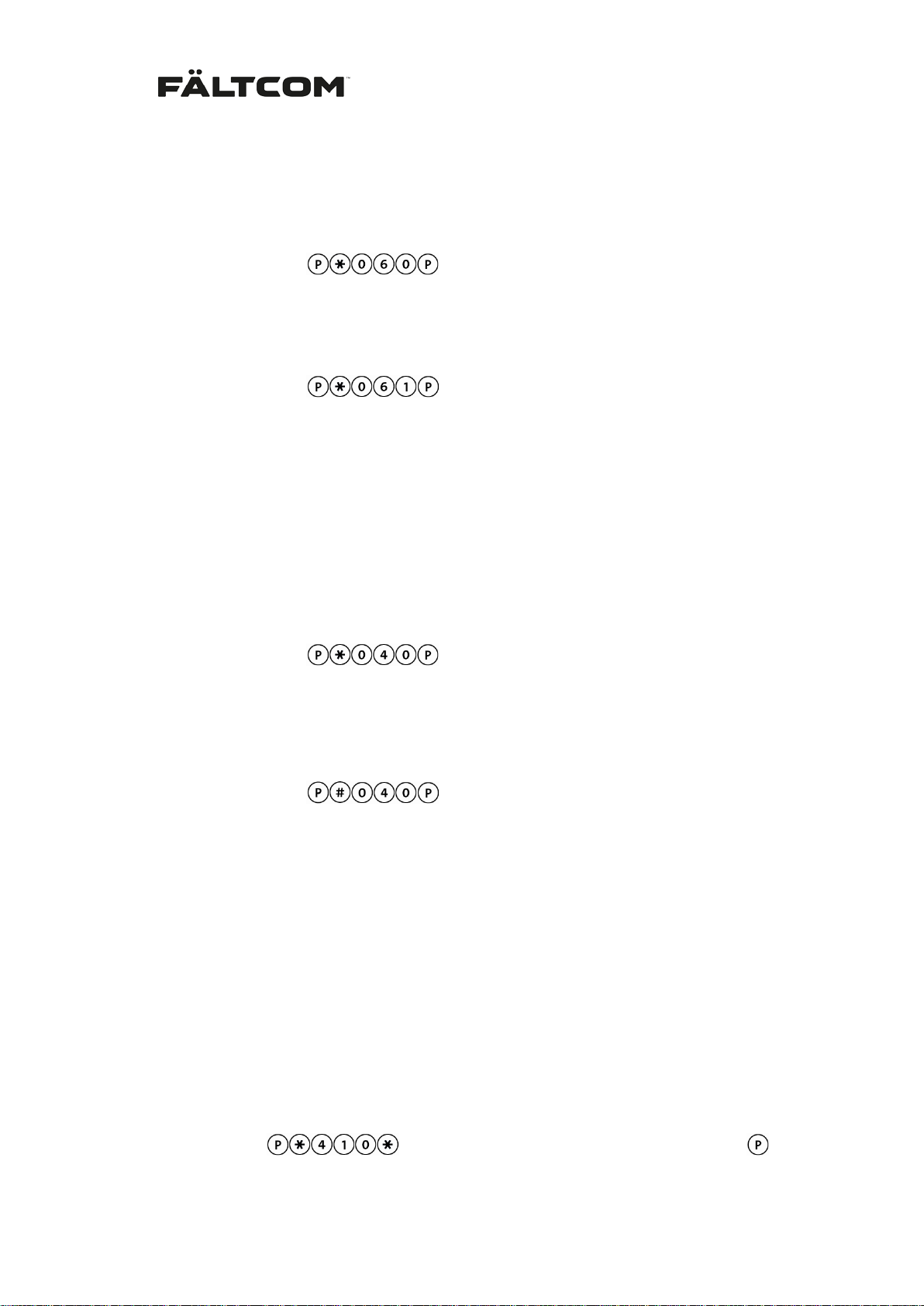
6.24 Alarm protocol
The CPC protocol is the default protoco l used in Fältcom ECII® Flex. An alternative protoco l
P100 is also available. This is activated by programming:
From keypad:
From phone:
To return to the CPC protocol:
From keypad:
From phone:
060 #
061 #
6.25 Dial tone detection
Fältcom ECII® Flex has a function which m akes it po ssible to first w ait for a dial tone before
the call out sequenc e starts. In default mode the Fältcom ECII® Flex waits 3 s econds and
then initiates the call. If dial tone detection is acti vated the Fältcom ECII® Flex w ill require a
425 Hz dial tone in order to initiate the call.
Dial tone detection is activated with:
From keypad:
From phone:
To deactivate the dial tone detec t ion:
040 #
From keypad:
From phone:
# 040 #
6.26 Speech messages
It is possible to record two different speech messages that can be played. One in the loudspeaker of the Fältcom ECII® Flex to inform and calm the passengers in the lift and one to
the receiver to identify the originating location of the alarm call. Each message can be 10
seconds long.
Speech message 1; for the cabin
This message is activated and played one time in the lift when the alarm is activated.
Recording of message 1:
From keypad:
From phone:
Fält Communications 201 6 ©
162187 Manual Fältcom ECII® Flex V024D 2016-02-23 Page 32 of 41
410 < wait for tone; read message. Max 10 seconds > #
< wait for tone; read message. Max 10 seconds >
Page 34
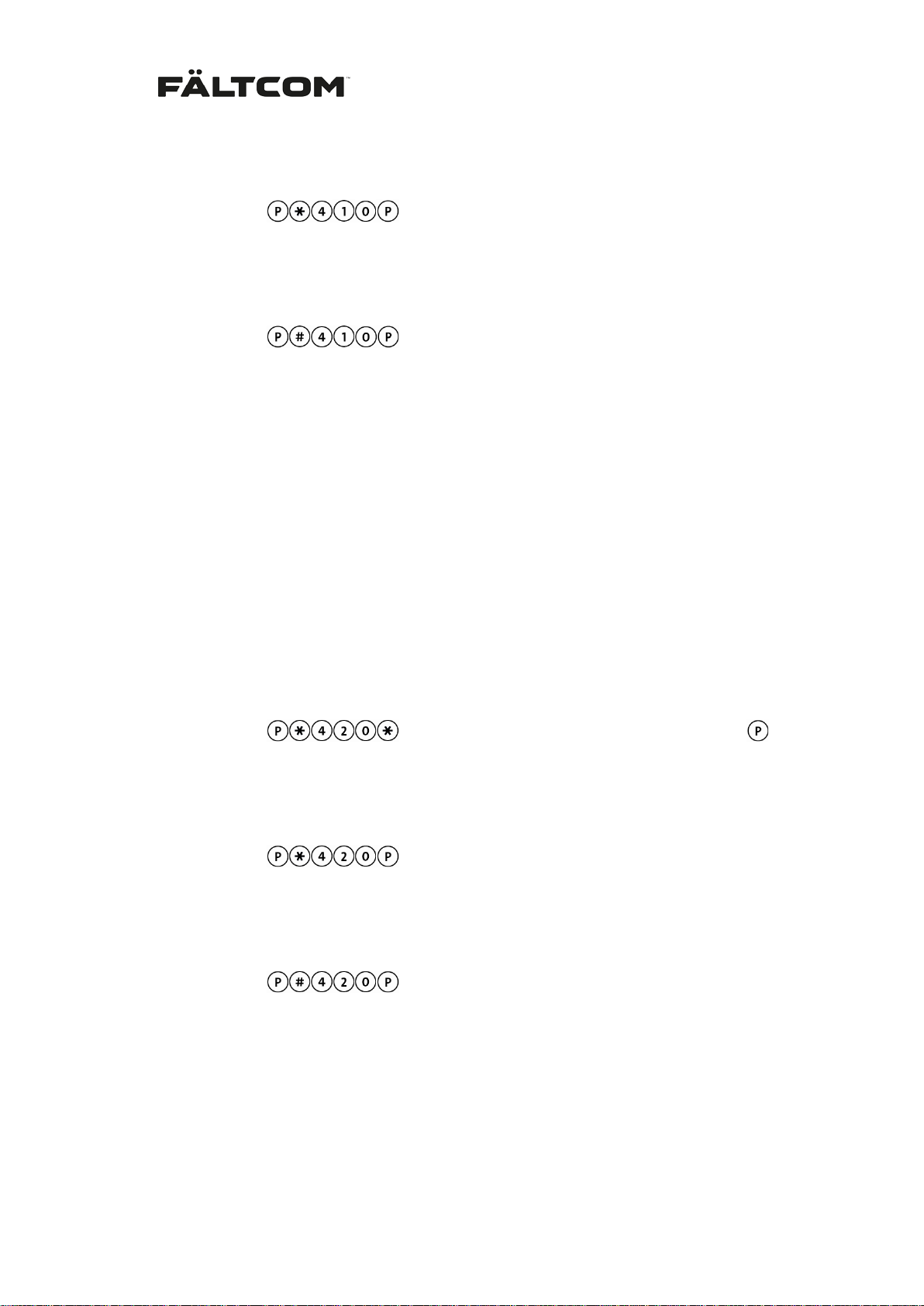
Listening to message 1:
From keypad:
From phone:
Deleting message 1:
From keypad:
From phone:
Note: When downloading a message using the Flex P rogrammer SW; the m essage must be
smaller then 128 kB. This is the allocated size in Flex memory.
410 #
# 410 #
Speech message 2; for the alarm receiver
This message is pla yed in the receiving telephone before the alar m call has been acknowledged by the alarm receiver. It is sto ppe d by pressing any digit on th e r ec eiver tel epho ne. For
simplified and disc onnected acknowledge the mes sage 2 is only played once. The receiver
can repeat the message 2 at an y time during the call by pressing ‘1’ on the te lephone handset.
Recording of message 2:
From keypad:
From phone:
Listening to message 2:
From keypad:
From phone:
Deleting message 2:
From keypad:
From phone:
Note: When downloading a message using the Flex P rogrammer SW; the m essage must be
smaller then 128 kB. This is the allocated size in Flex memory.
420 < wait for tone; read message. Max 10 seconds > #
420 #
# 420 #
< wait for tone; read message. Max 10 seconds >
Fält Communications 201 6 ©
162187 Manual Fältcom ECII® Flex V024D 2016-02-23 Page 33 of 41
Page 35
7 Alarm reception
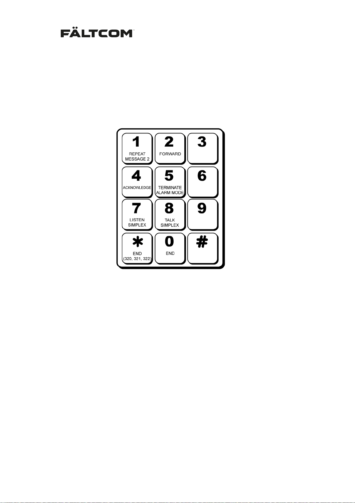
All tone dialing telephones (units with the keys * and #) can work as simple alarm receivers.
The telephone keypad is used to control alarm reception and to acknowledge the alarm unless the need for acknowledgment has been deactivated.
The most important key to learn is 4, used to acknowledge the alarm and set up the call.
7.1 Alarm call
When answering an incoming alarm call, the Fältcom ECII® Flex will play message 2 if that
has been programmed or play a 4-tone (”chirp”) for the receiver. The message or tone is
played every 5 seconds until the alarm is acknowledged. If the alarm receiver has not answered within 60 secon ds the Fältcom ECII® Flex will automatically disconnect and call the
next alarm number. The lift phone waits 10 seconds before dialing the next alarm number.
7.2 Acknowledging an alarm
Acknowledge the al arm with 4, ACKNOWLEDGE. A duplex v oice comm unication call is then
set up; as in a normal telephone call.
A call will be disconnected automaticall y three minutes after the last ke y pressing, i.e. three
minutes after the call is acknowledged. W ith thirty seconds to discon nection, a warning tone
will be heard. To prolong the call, press 4, ACKNOWLEDGE.
If functions “Sim plified ackno wledge” (320) is used the a larm is acknowledged by pressing
any digit on the telepho ne keypad. If “Disconnected acknowled ge” (321 or 323) are used the
alarm is acknowledged automatically upon connecting the call.
Fält Communications 201 6 ©
162187 Manual Fältcom ECII® Flex V024D 2016-02-23 Page 34 of 41
Page 36

7.3 Ending a call
End the alarm c all by pressing 0, E ND. If the alar m is ended with time disconn ection and the
call is not ack nowledged the Fältcom ECII® Flex will mak e a new al arm call to the next alarm
receiver. Please note that this will only happen when a lar ms are sent to a standard telepho ne.
When sending alarms to an automatic alarm centre no further calls will be made after the
alarm has been acknowledged.
If functions “Simplified acknowledge” (320) or “Disconnected acknowledge” (321, 323) are
used the alarm is disconnected by pressing *, END (320, 321, 323). No more calls will be
made.
7.4 Repeat Message 2
If the receiver wants to hear the recorded message 2 once again press 1, REPEAT MESSAG E 2. The message can be repeated at any time during the call.
7.5 Forwarding a call
If you want to forward the a larm to the next alarm receiver, press 2, FO RWARD. The alarm is
then closed, and th e lift p hone will call t he next program m ed alarm rec eiver. Ple ase note that
the alarm call has to be acknowledged before forwarding the call.
7.6 Termination of active alarm mode
If the function active alarm mode is activated and the product is in active alarm mode, i.e.
there has been an alarm and the Fältcom ECII® Flex is open for incoming calls, you can
close the incoming calls window by pressing the key 5, TERMINATE ALARM MODE. The call
is automatically disconnected.
7.7 Speech switching
If the automatic speech switching is not satisfactory, you can change to manual speech
switching 8, SIMPLEX TALK and 7, SIMPLEX LISTEN. Revert to automatic speech switching
by pressing 4, ACKNOWLEDGE.
7.8 Calls to a lift phone
7.8.1 Multiple units on the line
If answering function is activated, or if alarm mode function is programmed, and Fältcom
ECII® Flex is in active alarm mode, it is possible make a call to the Fältcom ECII® Flex from a
tone dialing phone or a mobile phone according to the following:
1. Dial the number to the lift phone.
2. After one ring signal the f irst Fältcom ECII® Flex ans wers and sends a modem (fax)
tone. Wait for the modem tone to stop and listen for a 3-tone message.
3. Press # and ID-number to the wa nted lif t phone (1-9). For instanc e #2 for l ift phone 2
Fält Communications 201 6 ©
162187 Manual Fältcom ECII® Flex V024D 2016-02-23 Page 35 of 41
Page 37

in the chain. Note t hat #1 m ust be pressed b y the caller eve n if onl y one lift phone is
mounted. The Fältcom ECII® Flex will reply with a nother 3-tone message indica ting
the correct device has answered the call.
4. Press 4 to activate voice connection.
5. Press 5 to terminate a possible active alarm mode. The call is then disconnected.
6. Press 7 to listen in simplex mode.
7. Press 8 to speak in simplex mode.
8. Press 3 to activate the speaker and microphone in the Speech Unit (if connected).
Press 3 again to go back to the Fältcom ECII® Flex speaker and microphone.
9. Press 0 to disconnect the call.
7.8.2 Single unit on the line
If the function 142 has been programmed the Flex will answer the call and go straight to
conversation mode. The Fältcom ECII® Flex will behave differently depending on the
acknowledgement settings:
For normal acknowledge (default setting) and 320 go through steps 4 – 8 above.
For acknowledgement functions 321 and 323 the Fältcom ECII® Flex will automatically go
to duplex conversati on on incoming calls. End t he call by hanging up or press on the receiver handset.
7.9 Volume control
Adjust the volume in the Fältcom ECII® Flex speaker b y using a screw driver to turn the volume control. The control is located on one of the sides of the Fältcom ECII® Flex.
- To increase the volume; turn the control counter clockwise and
- To decrease the volume; turn the control clockwise.
The Fältcom ECII® Flex will set the vo lume automatically as the volume control is t urned. The
new volume will be used in all following calls.
Please note that prev ious versions of the Fältcom ECII® Flex have a different procedur e for
the volume control:
To change the volume during a call on older vers ions then SW 0.2.4:
- Turn the volume control
- Ask the receiver to press ‘4’ on the receiver handset
- The new volume is set in the Fältcom ECII® Flex
Fält Communications 201 6 ©
162187 Manual Fältcom ECII® Flex V024D 2016-02-23 Page 36 of 41
Page 38
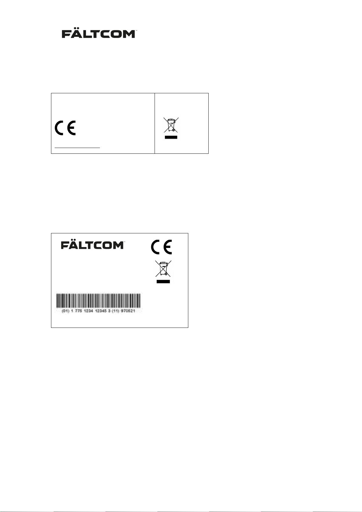
Liftphone Flex Unit
Rev z.z
8 Product label
Following is a description of the Fältcom ECII® Flex produc t lab el.
Part No 2187
Snr MCCCCC
W yyww
www.faltcom.com
The product label describes:
Part No 2187: Product part number (order number)
Snr MCCCCC: Serial number of the device.
Rev z.z: Hardware revision of the product.
W yyww: Production year and month.
Label on the box.
Fältcom ECII
®
Flex COP
Part No 2187 Rev z.z
Snr MCCCCC W yyww
www.faltcom.com
The box label describes same information as above but has additionally the barcode:
EAN-128 indicating XXXXZZYYWWCCCCC
XXXX: Part number
ZZ: Hardware revision
YYMM: Production year and m onth
CCCCC: Serial number
9 Warranty
There is a 1-year warrant y (12 m onths) from the date of deliver y covering f ailure due to f aults
in materials or the manufacturing process.
Warranty does not include:
- Incorrect or careless usage
- Damage caused by thunderstorms or air pollution.
Fält Communications 201 6 ©
162187 Manual Fältcom ECII® Flex V024D 2016-02-23 Page 37 of 41
Page 39

- Vandalism or intentional damage.
- Normal wear and tear.
Fält Communications AB r eserves the right to determ ine if the product will be repaire d or replaced. Warranty ceases to be valid if def ects occur due to inc orrect use, or ot her method of
application, or context than specified in this manual.
Fältcom ECII® F lex should only be used in th e context for which it is inten ded. Al l other form s
of usage will be cons idered as being s olel y at the user’s own risk. Only suitably q ualified persons are permitted to ins tall, program and start-up this produc t. Start-up is onl y allowed after
the product has been pr op erly ins talled . As a c ons equenc e Fält Comm unic ations AB declines
all liability for possible defects, operational disturbance, accidents etc. caused by lack of
knowledge or careles sness on the part of the user . The same principle is val id for all unauthorized changes made to the product.
Fält Communications AB r eserves the right to mak e changes to the product for func tional or
commercial reasons. T he company is not obliged to make immediate updates to reference
manuals.
10 Updates
Visit our web site to access the latest updates regarding market information and technical
documentation.
http://www.faltcom.com
11 Repair return procedure
Fält Communications AB o nly accepts returns that ha ve a valid a RMA number . Please contact Fält Communications AB support to recieve a RMA number.
Repaired products are sent back to customers as a regular post parcel with freight paid on the
assumption that the product is covered by warranty. If the investigation shows that the returned product has no def ects the customer is charged a s ervic e fee and f reight. T he cus tomer can ask for a quotation for repair of product not covered by warranty.
Fält Communications 201 6 ©
162187 Manual Fältcom ECII® Flex V024D 2016-02-23 Page 38 of 41
Page 40

12 Technical Data
Ext. power supply: 4-16 mA
Indications: Yellow and green LED during alarm
Sound and light indication when progr am ming
Test alarm/routine call: 1 time/day up to once every 30 days (selectable on/off)
Alarm receiver types: Contact your local distributor for information about alarm cen-
tres that can handle the CPC or P100 protocols.
All tone selection telephones, including mobile phones, can
also be used as alarm receivers
Protocol: CPC
P100
Speech exchange: Duplex or simplex
Signaling: DTMF
Calling: Tone selection
Incoming calls: Automatic (selectable on/off)
Casing: Stainless sheet steel 1.5 mm. Vandal proof.
Dimensions HxWxD: 100 x 90 x 19 mm (behind COP)
140 x 127 x 25 mm (with frame)
195 x 127 x 25 mm (with frame and alarm button)
Weight: 235 gram (with frame)
187 gram (behind COP)
310 gram (with frame and alarm button)
Fält Communications 201 6 ©
162187 Manual Fältcom ECII® Flex V024D 2016-02-23 Page 39 of 41
Page 41

13 Contact information
Fält Communications AB
Vasagatan 23
SE-903 29 UMEÅ, Sweden
Support: + 46 (0)90 18 39 27 or via e-mail: [email protected]
Phone: + 46 (0)90 18 39 00 (exchange)
Fax: + 46 (0)90 18 39 29
Homepage: http://www.faltcom.com
Fält Communications 201 6 ©
162187 Manual Fältcom ECII® Flex V024D 2016-02-23 Page 40 of 41
 Loading...