

Falmec Rondo Malizia, Iris Malizia, Ginevra Tile, Ninfea Tulip, Orchidea User Manual [de]
...Page 1

LIBRETTO ISTRUZIONI
INSTRUCTIONS BOOKLET
BEDIENUNGSSANLEITUNG
LIVRET D’INSTRUCTIONS
MANUAL DE INSTRUCCIONES
азлнкмдсаь ий щдлигмДнДсаа
INSTRUKCJE OBSŁUGI
Cod. 110030251 (CAPPE CLASSICHE)
Ed. 2013
Page 2

Gentile Signora/Signore, congratulazioni!
Lei ha acquistato una cappa di prestigio e di sicura qualità. Perché Lei possa ottenere le migliori
prestazioni, Le suggeriamo di seguire con attenzione le istruzioni per l’uso e manutenzione che troverà
in questo libretto; inoltre, per ordinare i filtri di ricambio al carbone attivo utilizzi l’apposito tagliando
che troverà allegato alla copertina.
Dear Sir/Madam, congratulations!
You have purchased a prestigious range hood of guaranteed quality. For best results, we suggest that
you carefully follow the operating and maintenance instructions provided in this booklet; in addition, to
order spare charcoal filters, use the special coupon on the cover.
Verehrte Kundin, verehrter Kunde
Kompliment! Sie haben eine qualitativ hochwertige Dunstabzugshaube erworben. Um ihre
Leistungsfähigkeit optimal nutzen zu können, sollten Sie die beiliegende Gebrauchs- und
Wartungsanleitung sorgfältig durchlesen und befolgen. Für die Bestellung der Ersatz-Aktivkohlefilter
verwenden Sie bitte den Coupon, der dem Deckblatt beiliegt.
Chère Madame/Cher Monsieur, félicitations!
Vous venez d’acheter une hotte haut de gamme. Pour en tirer les performances les meilleures
veuillez lire avec attention le mode d’emploi et la maintenance que vous trouvez dans ce manuel ;
pour commander les filtres de rechange au carbone actif veuillez vous servir du coupon annexé à la
couverture.
Enhorabuena Señora/Señor!
Ha comprado una campana extractora de prestigio y calidad segura. Para que pueda obtener las
mejores prestaciones, le sugerimos seguir con atención las instrucciones contenidas en este manual
para el uso y el mantenimiento. Para pedir los filtros de recambio de carbón activo, utilice el cupón
adjunto a la cubierta.
З˚ ФЛУ·ОЛ ФТЪЛКМУ Л ‚˚ТУНУН‡˜ТЪ‚ММУ ‚˚ЪflКМУ ЫТЪУИТЪ‚У. СОfl ЪУ„У, ˜ЪУ·˚ УМУ ‰‡‚‡ОУ М‡ЛОЫ˜¯Л
БЫО¸Ъ‡Ъ˚, НУПМ‰ЫП ‚МЛП‡ЪО¸МУ ТО‰У‚‡Ъ¸ ЛМТЪЫНˆЛflП ФУ ˝НТФОЫ‡Ъ‡ˆЛЛ Л ЫıУ‰Ы, НУЪУ˚ ‚˚ М‡И‰Ъ ‚ ˝ЪУП
ЛБ‰‡МЛЛ; НУП ЪУ„У, ‰Оfl Б‡Н‡Б‡ Б‡Ф‡ТМ˚ı ЩЛО¸ЪУ‚ М‡ ‡НЪЛ‚ЛУ‚‡ММУП Ы„О ЛТФУО¸БЫИЪ ТФˆЛ‡О¸М˚И Ъ‡ОУМ,
НУЪУ˚И ‚˚ ПУКЪ М‡ИЪЛ ФЛНФОММ˚П Н У·ОУКН.
Szanowni Państwo
Gratulujemy!
Zakupiliście prestiżowy okap kuchenny o gwarantowanej jakości. Dla uzyskania najlepszych
wyników zalecamy, by starannie przestrzegać instrukcji obsługi i konserwacji zawartych w
tej broszurze. Ponadto, do zamawiania zapasowych fi ltrów z węglem drzewnym, wykorzy-
stywać specjalny kupon załączony na okładce.
Page 3
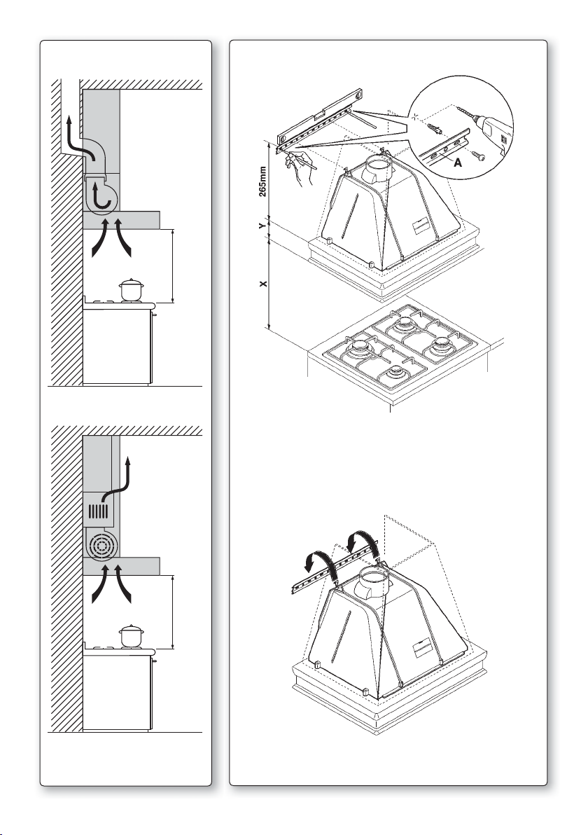
Fig. C1
Fig. 1
Fig. 2
1
Page 4
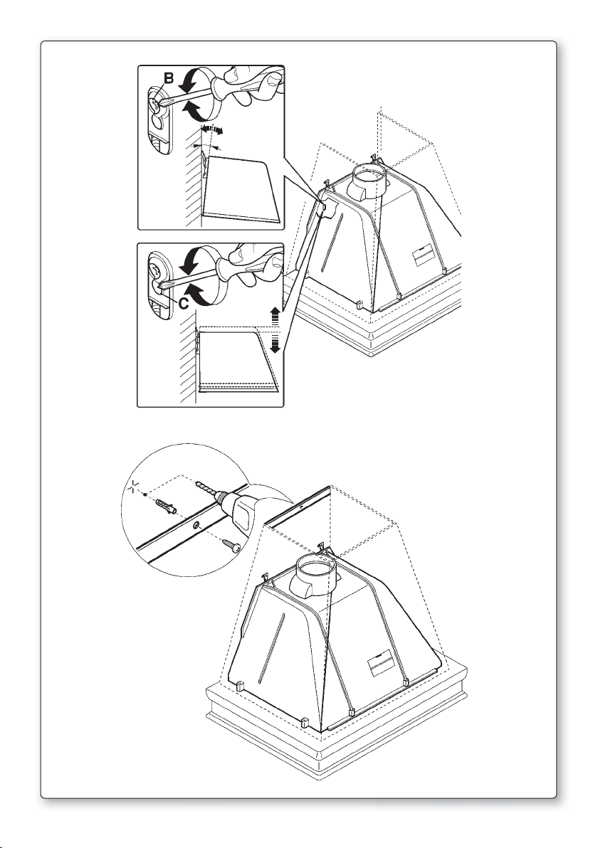
Fig. 3
Fig. 4
2
Page 5
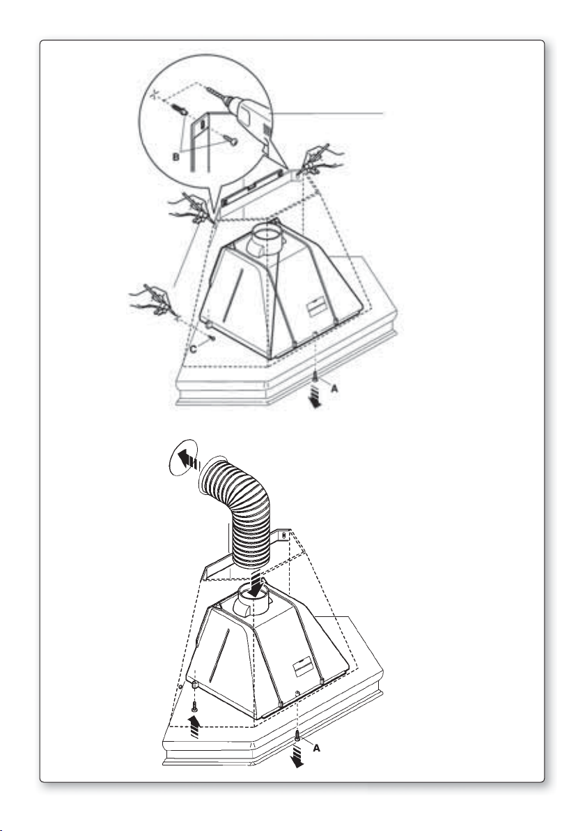
Fig. 5
Fig. 6
3
Page 6
A FASTENING HOLES
B HOB
Fig. 7
STIRRUP A
TOP SECTION
CENTER SECTION
HOOD UNIT
Fig. 8
4
Page 7
I
LIBRETTO ISTRUZIONI
A
Se l’apparecchio dovesse essere venduto o trasferito ad un’altra persona, assicurarsi che il
AVVERTENZE
È molto importante che questo libretto istruzioni sia conservato insieme all’apparecchiatura
per qualsiasi futura consultazione.
libretto venga fornito assieme, in modo che il nuovo utente possa essere messo al corrente
del funzionamento della cappa e delle avvertenze relative.
Queste avvertenze sono state redatte per la vostra sicurezza e per quella degli altri, Vi preghiamo, dunque, di volerlo leggere attentamente prima d’installare e di utilizzare l’apparecchio.
Questo apparecchio non deve essere utilizzato da bambini o persone infermi a meno che non
siano adeguatamente controllate da persone responsabili che si assicurino che l’apparecchio
sia utilizzato in sicurezza.
I bambini devono essere controllati da persona responsabile per assicurarsi che non giochino
con l’apparecchio.
Il lavoro di installazione deve essere eseguito, da installatori competenti e qualificati, secondo
le norme in vigore.
Se il cavo di alimentazione è danneggiato, esso deve essere sostituito dal costruttore o dal
suo servizio assistenza tecnica o comunque da una persona con qualifica similare, in modo
da prevenire ogni rischio.
Ogni eventuale modifica che si rendesse necessaria all’impianto elettrico per installare la
cappa dovrà essere eseguita solo da persone competenti.
È pericoloso modificare o tentare di modificare le caratteristiche di questo impianto. In caso di
riparazioni o mal funzionamento dell’apparecchio, non tentare di risolvere da soli il problema.
Le riparazioni effettuate da persone non competenti possono provocare danni.
Per eventuali interventi rivolgersi ad un Centro Assistenza Tecnica autorizzato ad eseguire
parti di ricambio.
Controllare sempre che tutte le parti elettriche, (luci, aspiratore), siano spente quando l’apparecchio non viene usato. Leggere tutto il libretto istruzioni prima di effettuare operazioni sulla
cappa.
L’utilizzo della cappa non può essere diverso da quello di aspiratori di fumi di cottura su
cucine domestiche.
Qualsiasi utilizzo diverso da questo solleva il costruttore da qualsiasi responsabilità.
Il peso massimo complessivo di eventuali oggetti posizionatio appesi (ove previsto) sulla
cappa non deve superare 1,5 Kg.
Dopo l’installazione delle cappe in acciaio inox bisogna eseguire la pulizia della stessa per
rimuovere i residui di collante protettivo e le eventuali macchie di grasso o oli.
Per questa operazione il costruttore raccomanda l’utilizzo delle salviette in dotazione, disponibili anche in acquisto.
L’utilizzo di altre tipologie di detergenti solleva il costruttore dalla responsabilità sui danni
che ne potrebbero derivare.
SICUREZZA AVVERTENZE
L’impianto elettrico è munito di collegamento a terra secondo le norme di sicurezza internazio-
nali; è inoltre conforme alle normative Europee sull’antidisturbo radio.
Non collegare l’apparecchio a condotti di scarico dei fumi prodotti dalla combustione (caldaie,
caminetti,ecc). Verificare che la tensione di rete corrisponda a quella riportata dalla targhetta
posta all’interno della cappa.
Non fare cotture a fiamma “libera” sotto la cappa. Controllare le friggitrici durante l’uso: I’olio
5
Page 8
surriscaldato potrebbe infiammarsi.
- Assicurarsi che vi sia una adeguata ventilazione nella stanza se la cappa è utilizzata con altri
apparecchi che utilizzano combustibili come gas o altro.
- Non accendere fiamme libere sotto la cappa.
- Non collegare l’apparecchio a condotti di scarico dei fumi prodotti dalla combustione (caldaie, caminetti, ecc).
- Assicurarsi che tutte le normative vigenti sullo scarico dell’aria all’esterno del locale siano
rispettate prima dell’utilizzo della cappa.
Prima di procedere a qualsiasi operazione di pulizia o di manutenzione, disinserire l’appa-
recchio togliendo la spina o agendo sull’interruttore generale. La casa costruttrice declina
ogni responsabilità per eventuali danni che possano, direttamente o indirettamente, essere
causati a persone, cose ed animali domestici in conseguenza alla mancanza di tutte le prescrizioni indicate nell’apposito libretto istruzioni e concernenti, specialmente, le avvertenze
in tema di installazione, uso e manutenzione dell’apparecchio.
- Rischio di incendio se la pulizia non è condotta secondo le istruzioni del presente libretto.
ATTENZIONE: parti accessibili possono essere calde quando usate con apparecchi di cottura.
- La lunghezza massima della vite di fissaggio del camino (fornita dal fabbricante) è di 10 mm.
AVVERTENZA: l’installazione delle viti o dei dispositivi di fissaggio non conforme alle presenti
istruzioni può comportare rischi di natura elettrica.
B
C
D
CARATTERISTICHE TECNICHE
I dati tecnici dell’elettrodomestico sono riportati su delle targhette, posizionate all’interno della
cappa.
INSTALLAZIONE
(parte riservata solo a persone qualificate per il montaggio della cappa)
La distanza fra il piano cottura e la parte più bassa della cappa da cucina è di norma almeno 65 cm (vedi figura C1). Tale distanza è misurata a rigore nel punto più basso della cappa
con tensione non di sicurezza. Sulla base di questa dettaglio previsto dalle norme Europee è
possibile ridurre la distanza su alcuni modelli come specificato nel catalogo generale. Se le
istruzioni del piano di cottura a gas specificano una distanza maggiore, bisogna tenerne conto.
Nella versione aspirante il tubo di uscita dei fumi deve avere un diametro non inferire a quello
del raccordo della cappa.
Nei tratti orizzontali il tubo deve avere una leggera inclinazione (10% circa) verso l’alto per
convogliare l’aria all’esterno dell’ambiente.
Ridurre al minimo le curve, verificare che i tubi abbiano una lunghezza minima indispensabile.
Rispettare le norme vigenti sullo scarico dell’aria all’esterno.
In caso di utilizzo contemporaneo di altre utenze (caldaie, stufe, caminetti, ecc.) alimentate a
gas o con altri combustibili, provvedere ad una adeguata ventilazione del locale in cui avviene
l’aspirazione dei fumi, secondo le norme vigenti.
Istruzioni di montaggio: vedi sez. “O” del presente manuale.
ALLACCIAMENTO ELETTRICO
(parte riservata solo a persone qualificate per l’allacciamento)
ATTENZIONE!
Prima di effettuare qualsiasi operazione all’interno della cappa scollegare l’apparecchio
dalla rete elettrica.
Assicurarsi che non vengano scollegati o tagliati fili elettrici all’interno della cappa; nel caso si verifichino tali situazioni contattare il centro assistenza più vicino. Per l’allacciamento
6
Page 9

elettrico rivolgersi a personale qualificato.
Il collegamento deve essere eseguito in conformità con le disposizioni di legge in vigore.
Controllare che la valvola limitatrice e l’impianto elettrico possano sopportare il carico dell’apparecchio (vedere targhetta caratteristiche tecniche al punto B). Alcuni tipi di apparecchi
possono essere dotati di cavo senza spina; in questo caso, la spina da utilizzare deve essere
dei tipo “normalizzato” tenendo conto che:
- il filo giallo-verde deve essere utilizzato per la messa a terra,
- il filo blu deve essere utilizzato per il neutro,
- il filo marrone deve essere utilizzato per la fase, il cavo non deve entrare in contatto con
parti calde aventi temperature superiori a 70 °C.
- montare sul cavo di alimentazione una spina adatta al carico e collegarla ad una adeguata
spina di sicurezza.
Se un apparecchio fisso non è provvisto di cavo di alimentazione e di spina, o di altro dispositivo che assicuri la disconnessione dalla rete, con una distanza di apertura dei contatti che
consenta la disconnessione completa nelle condizioni della categoria di sovratensione III, le
istruzioni devono indicare che tali dispositivi di disconnessione devono essere previsti nella
rete di alimentazione conformemente alle regole di installazione.
Il cavo di terra giallo/verde non deve essere interrotto dall’interruttore.
Prima di collegare l’apparecchio alla rete elettrica, controllare che:
- la tensione d’alimentazione corrisponda a quella indicata dalla targhetta caratteristiche
tecniche.
- la presa di terra sia corretta e funzionale.
- l’impianto di alimentazione sia munito di efficace collegamento di terra secondo le norme
vigenti.
- la presa o l’interruttore omnipolare usati siano facilmente raggiungibili con l’apparecchiatu-
ra installata.
La casa costruttrice declina ogni responsabilità nel caso le norme di sicurezza non vengano
rispettate.
E
CAPPA IN VERSIONE
AD EVACUAZIONE ESTERNA (aspirante)
In questa versione i fumi e i vapori della cucina vengono convogliati verso l’esterno attraverso
un tubo di scarico.
Il convogliatore di scarico che sporge sulla parte superiore della cappa deve essere collegato
con un tubo che conduce i fumi e i vapori in una uscita esterna.
In questa versione vanno tolti i filtri al carbone attivo se esistenti; per l’estrazione vedere
istruzioni al punto F. Quando la cappa da cucina viene utilizzata contemporaneamente ad altri
apparecchi che impiegano gas o altri combustibili, il locale deve disporre di sufficiente ventilazione secondo le norme vigenti.
Deviazione per la Germania:
Quando la cappa da cucina e apparecchi alimentati con energia diversa da quella elettrica
sono in funzione simultaneamente, la pressione negativa nel locale non deve superare i 4
Pa (4 x 10⁻⁵ bar).
F
CAPPA IN VERSIONE
A RICICLO INTERNO (filtrante)
In questa versione l’aria passa attraverso i filtri di carbone attivo per essere purificata e viene
riciclata nell’ambiente cucina.
7
Page 10
Controllare che i filtri al carbone attivo siano montati sul motore, in caso negativo applicarli
come indicato nelle istruzioni al punto H.
Se la cappa viene predisposta in versione filtrante rimuovere la valvola di non ritorno montata
sul raccordo di uscita del motore.
Per il miglior rendimento si consiglia di utilizzare la terza velocità in presenza di forti odori
e vapori, la seconda velocità nelle condizioni normali, la prima velocità per mantenere l’aria
pulita con bassi consumi di energia elettrica.
Si consiglia di mettere in funzione la cappa quando si inizia a cuocere e manteneria in funzione fino alla scomparsa degli odori.
G
FUNZIONAMENTO
1. COMANDO A 2 TASTI
LUCE - Interruttore A
Posizione 0: la luce sarà sempre spenta.
Posizione 1: la luce sarà sempre accesa.
VELOCITÀ - Interruttore B
Permette l’accensione e la regolazione delle velocità di esercizio dei motore, a seconda
delle versioni da 1 a 3, o tramite un variatore continuo di velocità.
SPIA - C
Gemma spia di funzionamento dei motore.
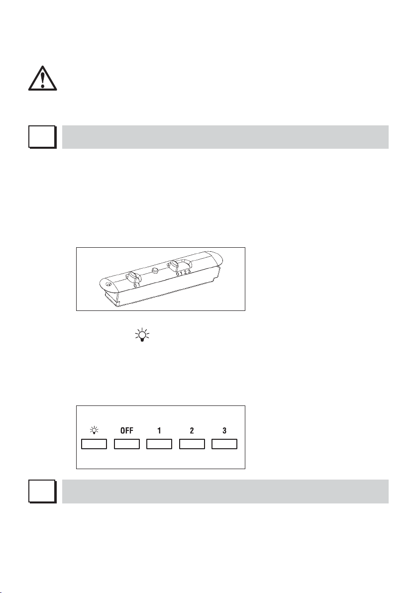
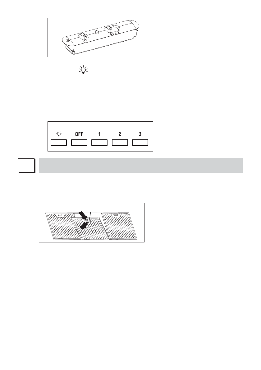
2. PULSANTIERA A 5 TASTI
LUCE - Pulsante
ON/OFF LUCE
MOTORE - Pulsante 1, 2, 3, OFF
1: avvia il motore alla velocità minima
2: avvia il motore alla velocità media
3: avvia il motore alla velocità massima
OFF: spegne il motore
8
H
FILTRI ISTRUZIONI PER L’ESTRAZIONE E LA SOSTITUZIONE
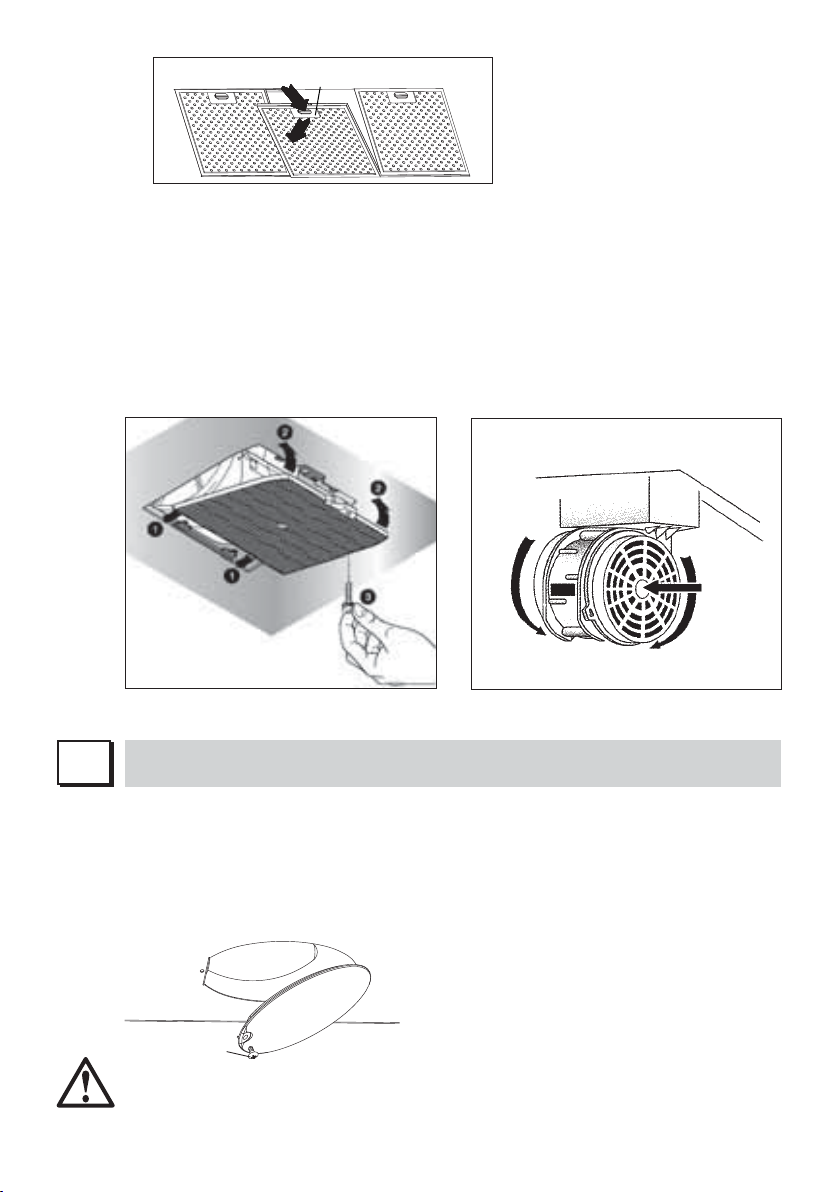
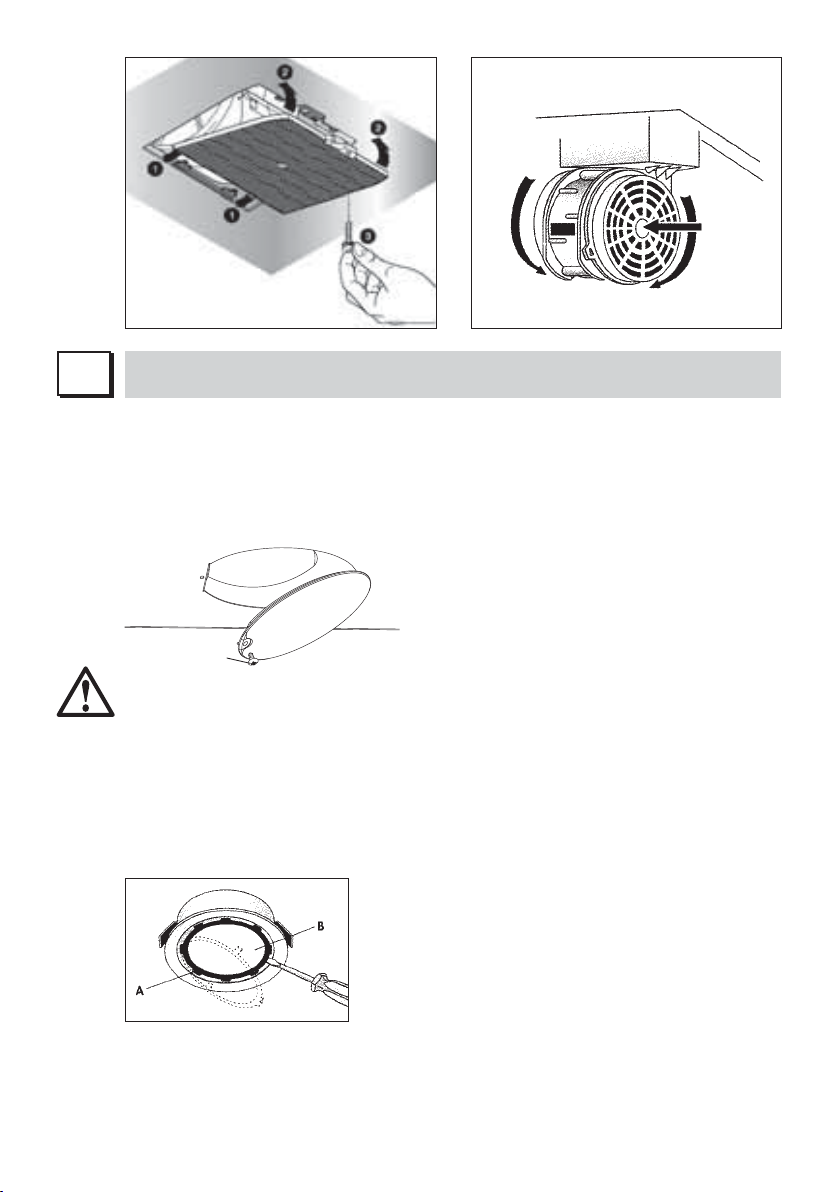
1. FILTRI METALLICI
Per l’estrazione dei filtro metallico antigrasso è sufficiente agire sulla maniglia A fino a
quando esce dalla guida anteriore; a questo punto, inclinando leggermente verso il basso,
farlo uscire dalla guida posteriore. Per l’inserimento invertire l’operazione.
Page 11
A
2. FILTRI AL CARBONE ATTIVO
Per la sostituzione dei filtri al carbone attivo si proceda come segue: togliere i filtri metallici
come indicato sopra. A questo punto si accede facilmente ai due filtri che sono agganciati
sul lato dx e sx del convogliatore.
Per il montaggio/sostituzione vedi figura.
Nel caso di cappa con camera motore il filtro è posizionato nella parte inferiore della
camera stessa. Per il montaggio/sostituzione vedi figura.
Per ordinare i nuovi filtri carbone rivolgersi al distributore/rivenditore.
SOLO PER ITALIA: Scaricare l’apposito modulo ordine filtro sul sito: www.falmec.com (acce-
dere sul menù a tendina assistenza).
ILLUMINAZIONE MONTAGGIO E SOSTITUZIONE
I
1. LAMPADA A PLAFONIERA
Per sostituire la lampada:
a) Accertarsi che l’apparecchio sia scollegato dalla rete elettrica.
b) Svitare la vite di sostegno A e rimuovere la plafoniera (vedi figura).
c) Sostituire la lampada con una dello stesso modello di quella originale (max 25 W, vedi
indicazione posta in prossimità della lampada).
A
ATTENZIONE! Lampade di forma e portata diverse da quella originale potrebbero danneggia-
re seria mente il vano illuminazione.
9
Page 12

2. FARETTO
Per sostituire la lampada del “Round halogen light”:
a) Accertarsi che l’apparecchio sia scollegato dalla rete elettrica.
b) Togliere, facendo leva con un cacciavite, l’anello di sup porto del vetro A.
c) Togliere il vetro B per accedere al vano lampada.
d) Sostituire la lampada con una analoga (alogena max 20 W, 12 Volt attacco G4).
e) Rimontare il vetro di protezione B fissandolo con l’apposito anello A.
Round halogen light
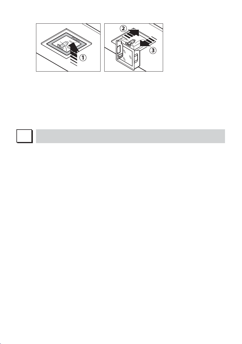
Per sostituire la lampada del “Square halogen light”:
a) Accertarsi che l’apparecchio sia scollegato dalla rete elettrica.
b) Aprire completamente il pannello fino ad un angolo di 90° (vedi figura) premendo su PUSH
c) Sostituire la lampada con una analoga (alogena max 20 W, 12 Volt attacco G4).
d) Richiudere i pannello. Se il pannello non si richiude correttamente ripetere l’operazione al
punto b.
Square halogen light
3. LAMPADA FLUORESCENTE
(parte riservata solo a personale qualificato)
Sostituzione del tubo fluorescente:
a) Scollegare l’apparecchio dalla rete di alimentazione;
b) Rimuovere l’eventuale pannello in acciaio svitando le viti di fissaggio;
c) Togliere il tubo fluorescente ruotandolo di 90° e sostituirlo con uno di analoghe caratteri-
stiche (8W-13W-21W-28W a seconda del modello);
d) Ricollegare l’apparecchio alla rete di alimentazione.
L
Una costante manutenzione garantisce un buon funzionamento ed un buon rendimento nel
MANUTENZIONE E PULIZIA
tempo. Particolari attenzioni vanno rivolte ai filtri metallici antigrasso ed ai filtri al carbone
attivo, infatti la pulizia frequente dei filtri e dei loro supporti garantisce che sulla cappa non si
accumulino grassi che sono pericolosi per la facilità di incendio.
1. FILTRI ANTIGRASSO METALLICI
Hanno la funzione di trattenere le particelle grasse in sospensione, pertanto si consiglia di
lavarli ogni mese in acqua calda e detersivo evitando di piegarli. Attendere che siano ben
10
Page 13
asciutti prima di rimontarli.
Per lo smontaggio e montaggio vedi istruzioni al punto H1. Si raccomanda costante fre-
quenza nell’operazione.
2. FILTRI AL CARBONE ATTIVO
Hanno la funzione di trattenere gli odori presenti nel flusso d’aria che li attraversa. L’aria
depurata per successivi passaggi attraverso i filtri viene rimessa nell’ambiente cucina. l
filtri al carbone attivo non possono essere lavati e vanno sostituiti mediamente ogni 3-4
mesi (dipende poi dall’uso). Per la sostituzione dei filtri al carbone attivo seguire le istru-
zioni come al punto H2.
3. PULIZIA ESTERNA
Si raccomanda di pulire le superfici esterne delle cappe almeno ogni 15 giorni per evitare
che le sostanze oleose o grasse possano intaccare le superfici in acciaio.
La pulizia della cappa va eseguita usando un panno umido con detersivo liquido neutro o
con alcool denaturato.
Nel caso di materiale con trattamento antimpronta (Fasteel) eseguire la pulizia solo con
acqua e sapone neutro utilizzando un panno morbido avendo cura di risciacquare e
asciugare accuratamente. Non si devono utilizzare prodotti contenenti sostanza abrasive,
panni con superfici ruvide o panni comunemente in commercio per la pulizia dell’acciaio.
L’utilizzo di sostanze abrasive e panni ruvidi danneggerà irreparabilmente il trattamento
superficiale dell’acciaio.
Conseguenza diretta del non rispetto di tali avvertenze sarà il deterioramento irreversibile
della superficie dell’acciaio.
Tali avvertenze dovranno essere conservate insieme al libretto istruzioni della cappa.
Il produttore declina ogni responsabilità qualora non vengano rispettate tali istruzioni.
4. PULIZIA INTERNA
É vietata la pulizia di parti elettriche o parti relative al moto re all’interno della cappa, con
liquidi o solventi;
Non usare prodotti contenenti abrasivi.
Effettuare tutte queste operazioni scollegando preven tivamente l’apparecchio dalla rete
elettrica.
M
La sua nuova apparecchiatura è coperta da garanzia. Le condizioni di garanzia sono riportate
N
GARANZIA
per esteso sull’ulti ma pagina di copertina di questo libretto.
La casa costruttrice non risponde delle possibili ine sattezze, imputabili ad errori di stampa
o di trascrizio ne, contenute nel presente libretto. Si riserva di appor tare ai propri prodotti
quelle modifiche che ritenesse necessarie o utili, anche nell’interesse dell’utenza, senza
pregiudicare le caratteristiche essenziali di fun zionalità e di sicurezza.
MONTAGGIO CAPPA PARETE RUSTICA
Fase 1
- Appoggiare alla parete la barra di sostegno (A-Fig. 1), ad un’altezza dal piano cottura deter-
minata dalla somma delle quote X+Y+265mm.
- Controllare con una bolla di livello l’allineamento orizzontale e segnare alle estremità della
barra n° 2 punti di foratura.
- Forare, inserire n° 2 tasselli ad espansione ø 8mm e fissare la barra con le relative viti.
Fase 2
- Agganciare la cappa alla barra di sostegno (Fig. 2).
11
Page 14

Fase 3
- Regolare l’allineamento della cappa tramite le viti delle attaccaglie (Fig. 3). La vite superiore
(B) regola la distanza dalla parete, quella inferiore (C) lo scorrimento verticale.
Fase 4
- Per evitare lo sganciamento della cappa dovuto ad una pressione sottostante, fissarla alla
parete con un tassello ad espansione e relativa vite attraverso l’apposito foro (Fig. 4).
MONTAGGIO CAPPA AD ANGOLO SENZA BARRA
Fase 1
- Svitare la vite metrica posteriore (A) e sganciare il gruppo motore dal fondo cappa (fig. 1).
- Controllare con una bolla di livello l’allineamento orizzontale e segnare n° 4 punti di foratura.
- Forare, inserire n° 2 tasselli ad espansione ø 8mm e fissare la cappa nella posizione deside-
rata tramite 2 viti B fissati nelle due asole poste sulla schiena superiore (Fig. 5).
- Fissare le due viti di sicurezza C posizionate sulla schiena inferiore.
Fase 2
- Dopo aver fissato la cappa, collegare il tubo flessibile al foro di scarico fumi e al raccordo
circolare della camera motore.
- Riagganciare il gruppo motore sul fondo della cappa e fissarlo tramite la vite metrica poste-
riore (A) (fig. 2).
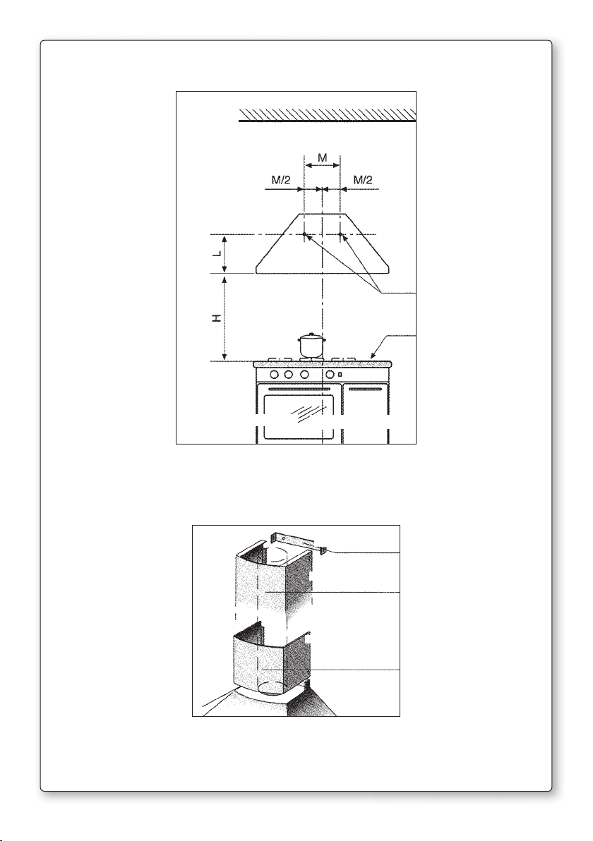
FISSAGGIO CAPPA SENZA CAMERA MOTORE
1) Rilevare la distanza (L) dal fondo della cappa al centro dei fori di fissaggio (fig. 7).
2) Rilevare la distanza (M) tra i due fori di fissaggio.
3) Far coincidere la linea di mezzeria del piano cottura con quella della cappa in modo tale
da suddividere a metà “M” (“M/2”).
4) La posizione in altezza dei fori da eseguire, rispetto al piano di cottura è di L+650 mm.
5) Eseguire i fori con il trapano per il posizionamento dei fischer (il diametro dei fori è deter-
minato dal tipo di fischer).
6) Prima di appendere la cappa, per poter in seguito assicurarsi che sia ben fissata, togliere:
- le griglie in acciaio se la cappa è con motore tangenziale
- tutto il gruppo ad incasso, svitando le viti che lo sorreggono al fondo, se la cappa è
dotata appunto di gruppo ad incasso.
7) Per evitare lo sganciamento della cappa dovuto ad una pressione sottostante, fissarla al-
la parete con un tassello ad espansione e relativa vite utilizzando gli appositi fori presenti
sul retro della cappa o le staffe del coperchio.
8) Appende la cappa.
9) Verificare, attraverso il buco sul fondo, che la cappa sia ben ancorata ai ganci dei fischer.
10) Regolare l’altezza della cappa tramite le viti poste sui ganci dei Fischer.
11) Montare le griglie in acciaio o il gruppo ad incasso.
12) Fissaggio kit camino (fig. 8):
- Fissare al muro, alla distanza opportuna, la staffa (A), usando le viti in dotazione;
- fissare la prolunga alla staffa (A) usando le viti in dotazione.
12
Page 15
GB
INSTRUCTIONS BOOKLET
A
WARNINGS
This instruction booklet must be kept together with the appliance for future reference. If the
appliance is sold or consigned to other parties, check that the booklet is supplied with it, to
ensure that the new user has the correct information on the operation of the range hood and
is aware of the warnings. These warnings have been provided for the your safety and the
safety of others. As a result, please read them carefully before installing and operating the
appliance.
This appliance is not intended for use by young children or infirm persons unless they have
been adequately supervised by a responsible person to ensure that they can use the appliance
safely. Young children should be supervised to ensure they do not play with the appliance.
The appliance must be installed by qualified personnel, in accordance with the standards in
force. If the supply cord is damaged, it must be re-placed by the manufacturer, its service
agent or similarly qualified persons in order to avoid a hazard. Any modifications that may be
required to the electrical system for the installation of the range hood must only be made by
qualified electricians.
It is dangerous to modify or attempt to modify the characteristics of this system. In the event of
malfunctions or if repairs are required to the appliance, do not attempt to solve the problems
directly.
Repairs performed by unqualified persons may cause damage. For all repair and other work on
the appliance, contact an authorised service/spare parts centre.
Always check that all the electrical parts (lights, exhaust device), are off when the appliance
is not being used. Read the entire instruction booklet before performing any operations on the
range hood.
The range hood must only be used for the exhaust of cooking fumes in home kitchens. The
manufacturer disclaims all liability for any other use of the appliance.
The maximum weight of any object placed above the hood, or hung to it (if possible) must
not exceed 1,5 kilos. After installing the stainless steel hood, clean it in order to remove any
residue of the protective glue, and stains of grease or oil. The manufacturer recommends its
cleaning cloth available for purchase. The manufacturer accepts no liability in case of damage caused by the use of different detergent types.
SAFETY WARNINGS
The electrical system features an earth connection in compliance with international safety
standards; furthermore, it is compliant with the European standard for electromagnetic compatibility.
Do not connect the appliance to flues (from boilers, fireplaces, etc.). Make sure the mains
Never cook on “open” flames under the range hood.
Check deep-fryers during use: superheated oil may be flammable.
voltage corresponds to the values on the rating plate located inside the range hood.
- Ensure there is adequate ventilation of the room when the rangehood is used at the same
time as appliances burning gas or other fuels.
- Do not flambe under the rangehood
- The exhaust air must not be discharged into a flue which is used for exhausting fumes from
appliances burning gas or other fuels.
- Ensure that all regulations concerning the discharge of exhaust air have been fulfilled before
you use the appliance.
13
Page 16
Before performing any cleaning or maintenance operations, disconnect the appliance by un-
plugging it or using the main switch. The manufacturer disclaims all liability for any damage
that may be directly or indirectly caused to people, things and animals due to the failure to
follow all the instructions provided in this booklet and above all the warnings relating to the
installation, operation and maintenance of the appliance.
- there is a fire risk if cleaning is not carried out in accordance with the instructions.
CAUTION: Accessible parts may become hot when used with cooking appliances.
- Max. length screw for fixing the chimney is 10 mm (provided by the manufacturer).
WARNING: Failure to install the screws or fixing device in accordance with these instructions
may result in electrical hazards.
Warning only for Australia: hood width less than 90 cm: use max. 4 hobs
B
C
D
TECHNICAL SPECIFICATIONS
The technical data pertaining to the electric appliance The technical specifications of the appliance are shown on the rating plates located inside the range hood.
INSTALLATION
(Section reserved for qualified installers of the range hood)
The distance between the hob and the lowest part of the rangehood is normally at least 65 cm
(see figure C1). This distance is measuresd in the lowest part of the rangehood not operating
at safety voltage. Based on this detail provided by European Standards, the distance may be
reduced in some models as specified in the general catalogue. If the instructions for installation for the gas hob specify a greater distance, this has to be taken into account.
In the outside exhaust version, the diameter of the fume discharge duct must be no smaller
than the range hood connection.
In the horizontal sections, the duct must slope slightly (around 10%) upwards, so as to better
convey the air outside of the room.
Avoid using angled pipes, make sure that the pipes are at least of the minimum length.
Comply with the current regulations on air discharge into the atmosphere.
If a boiler, stove, fireplace, etc. that uses gas or other fuels is being used at the same time,
make sure the room where the fumes are extracted is well ventilated, in compliance with the
current regulations.
Mounting instruction: see section “O” of the booklet.
ELECTRICAL CONNECTIONS
(Section reserved for qualified installers)
WARNING!
Before doing any work inside the range hood, disconnect the appliance from the mains
power supply.
Check that the wires inside the range hood are not disconnected or cut; if this is the case,
contact your nearest service centre. The electrical connections must be performed by qualified personnel.
The connections must be performed in compliance with the legal standards in force. Check
that the relief valve and the electrical system are able to support the load of the appliance (see
the technical specifications in point B).
Some types of appliance are supplied with a cable without plug; in this case, “standardised”
14
Page 17
plugs must be used, keeping in mind that:
- the yellow-green wire must be used for the earth,
- the blue wire must be used for the neutral,
- the brown wire must be used for the phase; the cable must not come into contact with hot
parts (over 70°C).
- fit a plug that is suitable for the load to the power cable, and connect it to a suitable power
outlet.
For appliances that come supplied with cable and plug please ensure they are plugged into a
circuit suitable for this appliance.
Please refer to a qualifed person. (See technical specifications in point B).
The manufacturer declines all liability if the safety standards are not observed.
E
RANGE HOOD WITH OUTSIDE DISCHARGE
(exhaust)
In this version, the fumes and steam from the kitchen are conveyed outside through an exhaust
duct.
The exhaust conveyor that protrudes from the upper part of the range hood must be connected
to a duct that carries the fumes and steam outside. In this version, the charcoal filters, if fitted,
should be removed; to do this, see the instructions in point F. There must be adequate ventilation of the room when the range hood is used at the same time as appliances burning gas or
other fuels, according to the standard.
Deviation for Germany:
When the range hood and appliances supplied with energy other than electricity are simultaneously in operation, the negative pressure in the room must not exceed 4 Pa (4x10 E-5 bar).
F
RECIRCULATING RANGE HOOD (with filter)
In this version, the air passes through charcoal filters for purification, and is then recirculated
back into the kitchen.
Check that the charcoal filters are fitted to the motor, and if not, install them as described in
the instructions in point H.
If the hood is of filtering type, remove the non-return valve fitted at the motor’s outlet.
For maximum efficiency, the third speed should be used when there are strong odours or a lot
of steam, the second speed in normal conditions, and the first speed for keeping the air clean
with minimum energy consumption. The range hood should be switched on when starting to
cook, and left on until the odours disappear.
G
OPERATION
1. TWO BUTTON CONTROL PANEL
LIGHT - Switch A
Position 0: the light is off.
Position 1: the light is on.
SPEED - Switch B
This is used to start and set the speed of the motor, from 1 to 3, or with continuous speed
variator, depending on the version.
LIGHT - C
Motor operation indicator light.
15
Page 18
2. FIVE BUTTON CONTROL PANEL
LIGHT- button
Pressed: the light is on
Released: the light is off
MOTOR button - 1, 2, 3, OFF
1: starts the motor at minimum speed
2: starts the motor at medium speed
3: starts the motor at maximum speed
OFF: stops the motor
H
FILTERS REMOVING AND REPLACING’S INSTRUCTIONS
1. METAL FILTERS
To remove the metal grease-trapping filter, simply pull the handle A until releasing it from
the front guide; then tilt it slightly downwards, and slide it out of the rear guide. To reposition the filter, repeat the operation in the reverse order.
A
2. CHARCOAL FILTERS
To replace the charcoal filters, proceed as follows: remove the metal filters as described
above. The two filters located at the ends of the motor can now be easily accessed.
To install the new fi lters see picture.
In case of hood with the motor box the fi lter is located on the botton part of the motor box.
To install the new fi lters see picture.
To order new charcoal fi lters contact the distributor/retailer.
VALID ONLY FOR ITALY: download the appropriate order form from: www.falmec.com (access
the assistance drop-down menu).
16
Page 19
LIGHTING ASSEMBLY AND REPLACEMENT
I
1. LIGHT BULB
To replace the light bulb:
a) Make sure the appliance is disconnected from the mains power supply.
b) Unscrew the support screw A and remove the light cover.
c) Replace the light bulb with the same model as the original (max 25 W, see the markings
near the light).
A
WARNING! Light bulbs with different shapes and power ratings from the original may seri-
ously damage the light compartment.
2. SPOTLIGHT
To replace the lamp for “Round halogen light”:
a) Make sure the appliance is disconnected from the mains power supply.
b) Remove, by levering with a screwdriver, the support ring A for the cover glass.
c) Remove the cover glass B to access the light compartment.
d) Replace the lamp with the same type (halogen, max 20 W, 12 Volt, G4 fitting).
e) Replace the glass cover B and fasten it using the special ring A.
Round halogen light
How to replace a square halogen light:
a) Check that the equipment is disconnected from the power supply.
b) Open the panel completely till 90° (see figure) pressing the PUSH button
c) Replace the lamp with a similar one (halogen, max 20 W, 12 Volt, G4 connection).
17
Page 20
d) Close the panel. If the panel does not close correctly repeat the operation at point b.
Square halogen light
3. FLUORESCENT TUBE
(Section reserved for qualified installers)
Replacing the fluorescent tube:
a) Disconnect the device from the mains;
b) Unscrew the fixing screws and remove the bottom panel;
c) Remove the fluorescent tube, by rotating through 90°, and replace it with one of similar
features (8W-13W-21W-28W according with the model);
d) Reconnect the device to the mains.
L
Constant maintenance ensures the correct operation and efficiency of the appliance over
MAINTENANCE AND CLEANING
time. Special attention should be paid to the metal grease-trapping filters and the charcoal
filters. Frequent cleaning of the filters and their supports will ensure that fats and grease do
not accumulate on the range hood, with the consequent risk of fire.
1. METAL GREASE-TRAPPING FILTERS
These trap the fat and grease particles suspended in the air, and therefore should be
washed every month in hot water and detergent, without bending them. Wait until they
are completely dry before repositioning them. To remove and replace these filters, see
the instructions in point H1. This operation should be performed at regular intervals.
2. CHARCOAL FILTERS
These trap the odours present in the stream of air that passes through them. The air is
purified by passing a number of times through the filters and being recirculated into the
kitchen. The charcoal filters cannot be cleaned, and should be replaced on average every
3-4 months (according to use). To replace the charcoal filters, see the instructions in point
H2.
3. CLEANING THE OUTSIDE OF THE APPLIANCE
It is advised to clean the external hood surfaces at least every 15 days in order to avoid
that oily or greasy substances affect the steel surfaces.
The ouside of the range hhod should be cleaned using a damp cloth and neutral liquid
detergent or denatured alcohol.
In case of fingerprint-less finish (fasteel) clean only with water and neutral soap using
clean with a soft cloth, rinse and wipe dry thoroughly. Do not use products that contain
abrasive substances, rough cloths or cloths specifically designed for cleaning steel. Using
abrasive substances or rough cloths will inevitably damage the finish of steel.
The steel surface will be irrevocably damaged if the instructions above are not complied
with.
Keep these instructions together with the instructions for use of your hood.
The manufacturer accepts no liability for any damage caused by non-compliance with the
instructions above.
18
Page 21
4. CLEANING THE INSIDE OF THE APPLIANCE
The electrical parts or parts of the motor assembly inside the range hood must not be
cleaned using liquids or solvents.
Do not use abrasive products.
All the above operations must be performed after having disconnected the appliance from the
mains power supply.
M
The new equipment is covered by warranty. The warranty conditions are provided by the
N
WARRANTY
distributor.
The manufacturer is not liable for any inaccuracies in this booklet resulting from printing or
transcription errors. The manufacturer reserves the right to modify its products as it considers necessary or in the interests of the user, without compromising their essential safety and
operating characteristics.
FOR WALL-MOUNTED RUSTIC HOOD
Step 1
- Rest the support batten (A-Fig. 1) against the wall at a height above the hob determined by
the sum of the values X+Y+265 mm.
- Use a spirit level to make sure it is perfectly horizontal and make 2 marks at the ends of the
batten where the 2 holes are to be drilled.
- Drill the holes, insert the two ø 8mm screw anchors and fasten the batten using the relevant
screws.
Step 2
- Hook the hood onto the support batten (Fig. 2).
Step 3
- Adjust the alignment of the hood using the screws on the brackets (Fig. 3). The upper screw
(B) is used to adjust the distance from the wall, and the lower screw (C) the vertical sliding
Step 4
- In order to prevent the hood from unhooking owing to pressure from underneath, fasten it
to the wall with a screw anchor and relevant screw inserted in the appropriate hole (Fig. 4).
FOR CORNER HOODS WITHOUT BAR
Step 1
- Undo the rear metric screw (A) and remove the motor from the bottom of the hood (fig. 1).
- Check the horizontal alignment with a spirit level and mark the 4 holes to be drilled.
- Drill the holes, insert 2 x 8mm dia. screw anchors and fix the hood in the desired position,
using 2 screws B fixed in the two slots in the top back panel (Fig. 5).
- Fit the safety screws C in the bottom back panels (Fig. 5).
Step 2
- After having fixed the hood, connect the flexible hose to the fume outlet hole and to the cir-
cular pipe fitting of the motor chamber.
- Replace the motor at the bottom of the hood and secure it with the rear metric screw (A)
(fig. 2).
19
Page 22

MOUNTING THE RANGE HOOD WITHOUT MOTOR
CHAMBER
1) Measure the distance (L) from the bottom of the range hood to the centre of the mounting
holes (Fig. 7).
2) Measure the distance (M) between the two mounting holes.
3) Line up the centre of the cooktop with the centre of the range hood. Is: L+650 mm.
4) The height of the holes to be drilled above the cooktop is calculated by adding (L) to (H),
where (H) is defined by point C-1.
5) Drill the holes for the Fischer screw anchors (the diameter of the holes depends on the type
of screw anchor).
6) Before hanging and securing the range hood, remove:
- the steel grilles for range hoods with tangential motors
- the entire build-in assembly, if fitted, by unscrewing the screws that secure it to the bottom.
7) To avoid hood unhooking due to underneath pressure, fix it to the wall with a screw anchor
and related screw, by using the appropriate holes at the back of the hood or the cope flasks.
8) Hang the range hood.
9) Check, through the hole at the bottom, that the range hood is properly anchored to the
Fischer hooks.
10) Adjust the height of the range hood using the screws on the Fischer hooks.
11) Fit the steel grilles or the build-in assembly.
12) Mounting instruction for chimney (fig. 8):
- Fasten bracket (A) to the wall, at the correct distance;
- Fasten the upper part of the extension to bracket (A).
20
Page 23

D
BEDIENUNGSANLEITUNG
A
Sollte das Gerät verkauft bzw. einer anderen Person übergeben werden, muss die Bedie-
Diese Hinweise sind für Ihre Sicherheit und die anderer Personen abgefasst worden. Daher
HINWEISE
Diese Bedienungsanleitung muss unbedingt zusammen mit dem Gerät aufbewahrt werden,
um in Zukunft nachgeschlagen werden zu können.
nungsanleitung unbedingt mitgeliefert werden, damit der neue Benutzer mit dem Betrieb der
Dunstabzugshaube und den diesbezüglichen Hinweisen vertraut werden kann.
sollten Sie die Bedienungsanleitung vor der Installation und Verwendung des Gerätes aufmerksam durchlesen.
Das Gerät darf nicht von Kindern bzw. Behinderten benutzt werden, es sei denn diese werden
von verantwortungsvollen Personen, die dafür Sorge tragen, dass das Gerät sicher verwendet
wird, überwacht.
Kinder müssen von einer von verantwortungsvollen Person überwacht werden, damit sie nicht
mit dem Gerät spielen.
Die Installation hat den geltenden Vorschriften gemäß von kompetenten, qualifizierten Installateuren durchgeführt zu werden.
Beschädigte Speisekabel sind vom Hersteller bzw. von dessen Kundenservice bzw. von einer
Person mit ähnlicher Qualifikation auszuwechseln, um Gefahren vorzubeugen.
Eventuelle erforderliche Änderungen, die für die Installation der Dunstabzugshaube an der
elektrischen Anlage durchgeführt werden müssen, dürfen ausschließlich von kompetenten
Personen vorgenommen werden.
Es ist gefährlich, die Eigenschaften dieser Anlage abzuändern bzw. versuchen abzuändern.
Bei Reparaturen bzw. Betriebsstörungen des Gerätes nicht versuchen, das Problem alleine
zu lösen.
Die Reparaturen, die von nicht kompetenten Personen durchgeführt werden, können Schäden
verursachen.
Sich für eventuelle Eingriffe an einen zugelassenen Kundenservice, der über die geeigneten
Ersatzteile verfügt, wenden.
Wenn das Gerät nicht benutzt wird, müssen alle elektrischen Teile (Beleuchtung, Absaugvorrichtung) ausgeschaltet sein. Vor Durchführung von Arbeitsvorgängen an der Dunstabzugshaube die Bedienungsanleitung lesen.
Die Dunstabzugshaube darf ausschließlich zum Absaugen des Dampfes, der beim Kochen in
einer Haushaltsküche entsteht, verwendet werden.
Bei anderen Einsätzen wird der Hersteller von jeder Haftung befreit.
Das Gesamtgewicht von Gegenständen, die eventuell auf die Dunstabzugshaube positioniert
bzw. an diese gehängt werden (falls vorgesehen), darf höchstens 1,5 Kg betragen. Nach der
Installation von Edelstahlhauben muss man diese reinigen, um Schutzkleberreste und eventuelle Fett- und Ölflecken zu entfernen. Der Hersteller empfiehlt für doesen Arbeitsvorgang
die Verwendung der mitgelieferten Reinigungstücher.
Die Verwendung anderer Reinigungsmittel befreit den Hersteller von jeder Haftung für eventuelle auf deren Benutzung zurückzuführende Schäden.
SICHERHEITSBESTIMMUNGEN
Die elektrische Anlage ist mit einer Erdung ausgestattet, die den internationalen Sicherhei-
tsvorschriften entspricht; sie erfüllt außerdem die europäischen Entstörungsvorschriften.
21
Page 24

Das Gerät auf keinen Fall an die Ablassleitungen von Rauch, das durch Verbrennung entsteht
Der Mindestsicherheitsabstand zwischen Kochebene und Dunstabzugshaube muss minde-
Auf keinen Fall unter der Dunstabzugshaube auf “offenem Feuer” kochen. Die Friteusen wäh-
Für eine ausreichende Lüftung im Raum sorgen, wenn die Dunstabzugshaube zusammen mit
- Kein offenes Feuer unter der Haube anzünden.
- Das Gerät auf keinen Fall an die Ablassleitungen von Rauch, das durch Verbrennung entsteht
- Sich vergewissern, dass alle gelten Vorschriften bezüglich der Luftablasses außerhalb des
(Heizkessel, Kamine, usw...), anschließen. Sich vergewissern, dass die Netzspannung mit den
im Inneren der Dunstabzugshaube angegebenen Daten übereinstimmt.
stens 65 cm betragen.
rend der Benutzung kontrollieren: das überhitzte Öl könnte sich entzünden.
anderen Geräten, die mit Brennstoffen und ähnlichen Stoffen arbeiten, verwendet wird.
(Heizkessel, Kamine, usw...), anschließen.
Raumes erfüllt werden, bevor man die Dunstabzugshaube benutzt.
Vor Durchführung von Reinigungs- oder Wartungsarbeiten muss man die Stromversorgung
unterbrechen, indem man den Stecker zieht bzw. den Hauptschalter betätigt. Der Hersteller
lehnt jede Haftung für eventuelle direkte oder indirekte Schäden an Personen, Gegenständen
und Haustieren ab, die auf die Nichteinhaltung der in der vorliegenden Bedienungsanleitung
enthaltenen Vorschriften zurückzuführen sind und insbesondere die Installation, Bedienung
und Wartung des Gerätes betreffen.
- Wenn die Reinigung nicht entsprechend den Anweisungen erfolgt, besteht Brandgefahr.
VORSICHT: Erreichbare Bauteile könnten sich erhitzen, wenn sie Kochgeräten verwendet
werden.
- Die max. Länge der Schrauben zur Befestigung des Rauchfangs beträgt 10 mm (vom Hersteller gestellt).
WARNUNG: Erfolgt die Installation der Schrauben oder Befestigungsvorrichtungen nicht
entsprechend den vorliegenden Anweisungen, führt dies zu Gefahr durch Stromschlag.
22
B
C
TECHNISCHE MERKMALE
Die technischen Daten des Elektrogeräts sind an den Typenschildern im Innern der Dunstabzugshaube angegeben.
INSTALLATION
(Dieser Abschnitt ist Fachpersonal mit der für die Montage der Dunstabzugshaube erforderlichen Qualifikation vorbehalten)
Der Abstand zwischen Kochebene und dem unteren Teil der Abzugshaube muss normalerweise mindestens 65 cm betragen (siehe Abbildung C1). Dieser Abstand muss unbedingt am
untersten Punkt der Haube ohne Sicherheitsspannung gemessen werden. Ausgehend von
diesem von den Europäischen Normen vorgesehenem Detail kann man den Abstand an einigen Modellen reduzieren, wie es im Hauptkatalog spezifiziert wird. Wenn die Anweisungen der
Gaskochebene einen größeren Abstand vorsehen, muss dies berücksichtigt werden.
In der Abluftversion kann der Durchmesser des Rauchablasses nicht kleiner als der des Dunstabzugshaubenanschlusses sein.
In den waagrechten Abschnitten muss das Rohr leicht nach oben geneigt sein (ca. 10%), um
die Luft nach außen zu leiten.
Die Kurven auf ein Minimum reduzieren und prüfen, ob alle Rohre die erforderliche Mindestlänge aufweisen.
Die geltenden Vorschriften bezüglich des Luftablasses nach draußen beachten.
Bei gleichzeitiger Verwendung anderer mit Gas oder anderen Brennstoffen gespeister Ver-
Page 25

braucher (Heizkessel, Öfen, Kamine, usw...) für eine angemessene, vorschriftsmäßige Lüftung
des Raumes, in dem die Rauchabsaugung erfolgt, sorgen.
Montageanleitungen: siehe Abschnitt “O” der vorliegenden Bedienungsanleitung.
D
E
ELEKTRISCHER ANSCHLUSS
(Dieser Abschnitt ist Fachpersonal mit der für den Stromanschluss erforderlichen Qualifikation vorbehalten)
ACHTUNG!
Vor jedem Eingriff im Innern der Haube muss das Gerät vom Stromnetz getrennt werden.
Sicherstellen, dass die Stromkabel im Innern der Dunstabzugshaube nicht abgeklemmt oder
durchgeschnitten werden; sollte dies dennoch vorkommen, den nächst gelegenen Kundendienst kontaktieren.
Der Anschluss muss unter Befolgung der gültigen Rechtsvorschriften erfolgen. Sicherstellen,
dass das Reduzierventil und die Elektroanlage der Geräteleistung entsprechen (siehe technische Spezifikationen in Punkt B). Einige Gerätetypen können mit einem Kabel ohne Stecker
ausgestattet sein, in diesem Fall ist ein „genormter“ Stecker zu verwenden, wobei folgendes
zu beachten ist:
- Der gelb/grüne Draht ist für die Erdung zu benutzen;
- der blaue Draht ist für den Nullleiter, und
- der braune Draht für die Phase bestimmt. Das Kabel darf auf keinen Fall mit heißen Teilen in
Berührung kommen (über 70°C).
- Am Netzkabel einen der Geräteleistung entsprechenden Stecker anbringen und diesen in
eine Sicherheits- Steckdose stecken.
Bei Geräten, die mit Kabel und Stecker ausgestattet geliefert werden, muss man sicherstellen,
dass sie mit einem geeigneten Kreislauf verbunden werden. Sich an eine qualifizierte Person
wenden (siehe technische Spezifikationen in Punkt B).
Die Herstellerfirma ist nicht haftbar, wenn die Unfallverhütungsvorschriften nicht eingehalten werden.
HAUBE MIT ABLUFTBETRIEB (absaugend)
Bei dieser Ausführung wird der während des Kochens entstehende Dampf durch ein Abzugsrohr nach außen abgeführt.
Der sich oberhalb der Haube befindliche Rauchzug ist an ein Abzugsrohr anzuschließen, über
das Rauch und Dampf zu einem Auslass ins Freie geleitet werden. Bei dieser Ausführung
sind eventuell vorhandene Aktivkohlefilter wie in Punkt F beschrieben zu entfernen. Wenn die
Dunstabzugshaube gleichzeitig mit anderen Geräten benutzt wird, die mit Gas oder anderen
Brennstoffen betrieben werden, muss eine ausreichende Belüftung des Raums gesorgt werden.
Germany (Feuerungsverordnung vom 31-01-1986 und DVGW-TRGI 1986, Amtsblatt G 600):
Bei gleichzeitigem Betrieb der Dunstabzugshau-be im Abluftbetrieb und Feuerstätten darf im
Aufstellraum der Feuerstätte der Unterdruck nicht größer als 4 Pa (4 x 10⁻⁵ bar) sein.
F
HAUBE MIT UMLUFTBETRIEB (filtrierend)
Bei dieser Ausführung strömt die Luft durch Aktivkohlefilter, wo sie gefiltert und erneut an
den Raum abgegeben wird. Sicherstellen, dass die Aktivkohlefilter am Motor installiert sind,
andernfalls müssen sie wie unter Punkt H beschrieben installiert werden.
23
Page 26

Bei Dunstabzugshauben im Umluftbetrieb empfehlen wir die Rückstauklappe, die am Ausgangsverbindungsstück des Motors montiert ist, zu entfernen.
Für optimale Leistung ist es ratsam, bei starker Geruch- und Dampfbildung die dritte Dreh-
zahlstufe, und unter normalen Bedingungen die zweite Stufe einzustellen. Die erste Drehzahlstufe dient dazu, die Luft bei geringem Energieverbrauch sauber zu halten. Die Haube
sollte bei Kochbeginn eingeschaltet, und erst wieder ausgeschaltet werden, wenn der Raum
vollkommen geruchsfrei ist.
G
ARBEITSWEISE
1. ZWEI-SCHALTER-STEUERUNG
LICHT - Schalter A
Stellung 0: Licht immer ausgeschaltet.
Stellung 1: Licht immer eingeschaltet.
DREHZAHL - Schalter B
Zum Einschalten und Einstellung der Betriebsdrehzahl des Motors, je nach Ausführung
Drehzahlstufe 1 bis 3 oder mittels stufenlosem Drehzahlregler.
KONTROLLLEUCHTE - C
Betriebskontrollleuchte des Motors.
2. BEDIENFELD MIT 5 TASTEN
LICHT – Taste
ON/OFF LICHT
MOTOR - Taste 1, 2, 3, OFF
1: startet den Motor mit Mindestdrehzahl
2: startet den Motor mit mittlerer Drehzahl
3: startet den Motor mit Höchstdrehzahl
OFF: schaltet den Motor aus
24
H
ANLEITUNGEN FÜR AUSBAU UND ERSATZ
1. METALLFILTER
Zur Entfernung des Metall-Fettfilters genügt es, am Griff A (Siehe Abb.) zu ziehen, bis der
Filter aus der vorderen Führungsschiene austritt. Nun leicht nach unten neigen, damit
er auch aus der hinteren Führungsschiene austritt. Beim Einsetzen des neuen Filters in
umgekehrter Reihenfolge vorgehen. Die Metall- Fettfilter sind spulmaschinenfest.
Page 27

A
2. AKTIVKOHLEFILTER
Um die Aktivkohlefilter auszuwechseln, wie folgt vorgehen: die Metallfilter, wie zuvor
erklärt, entfernen. Auf diese Weise kann man die zwei Filter, die an der rechten und linken
Seite des Leitblechs befestigt sind, leicht erreichen.
Für die Montage/das Auswechseln siehe Abb.
Im Falle von Dunstabzugshauben mit Motorkammer befindet sich der Filter im unteren
Kammerteil. Für die Montage/das Auswechseln siehe Abb.
Zur Bestellung neuer Karbonfilter bitte an die Vertragshandlung/Vertriebsunternehmen.
NUR FÜR ITALIEN: Entsprechendes Formular von der Internetseite: www.falmec.com herun-
terladen (Zugriff über Pull-down-Menü).
BELEUCHTUNG MONTAGE UND ERSATZ
I
1. DECKENLAMPE
Die Lampe wie folgt auswechseln:
a) Das Gerät darf nicht an das Stromnetz angeschlossen sein.
b) Die Stützschraube A ausdrehen und die Deckenlampe entfernen.
c) Die Lampe mit dem gleichen Modell wie das Original auswechseln (max. 25 W, siehe An-
gaben in Lampennähe).
A
ACHTUNG! Lampen mit anderer Form und Leistung als die Originallampe können das Be-
leuchtungsfach ernsthaft beschädigen.
2. LAMPE
Die lampe “Round halogen light” zu ersetzen:
a) Sicherstellen, dass das Gerät vom Stromversorgungsnetz getrennt ist.
25
Page 28

b) Den Haltering des Glasplättchens A durch eine leuchte Hebelbewegung mit einem
Schraubenzieher entfernen
c) Das Glasplättchen B entfernen, um Zugang um Lampenfach zu haben.
d) Die Lampe durch eine neue desselben Typs ersetzen (Halogenleuchte, max. 20 W, 12 Volt
Anschluss G4).
e) Das Glasplättchen B wieder anbringen und mit dem Haltering A befestigen.
Round halogen light
Auswechseln der Lampe “Square halogen light”:
a) Sich vergewissern, dass das Gerät nicht an das Stromnetz angeschlossen ist.
b) Die Platte vollständig bis zu einem Winkel von 90° öffnen (siehe Abbildung), indem man auf
PUSH drückt.
c) Die Lampe mit einer Lampe desselben Typs auswechseln (Halogenlampe max. 20 W, 12
Volt Anschluss G4).
d) Die Platte wieder schließen. Wenn sich die Platte nicht korrekt schließen lässt, den in Punkt
b) beschriebenen Vorgang wiederholen.
Square halogen light
3. LEUCHTSTOFFLAMPE (dem qualifizierten Personal vorbehalten)
Auswechseln des Leuchtstoffrohrs:
a) Das Gerät vom Stromnetz trennen;
b) Die eventuelle Stahlplatte entfernen, indem man die Befestigungsschrauben ausdreht.
Das Leuchtstoffrohr herausnehmen, indem man es um 90° dreht, und mit einem Rohr mit den
gleichen Eigenschaften ersetzen (8W-13W-21W-28W je nach Modell);
c) Das Gerät wieder an das Stromnetz anschließen.
L
Nur durch eine konstante Wartung ist ein einwandfreier Betrieb und eine lange Lebensdauer
WARTUNG UND REINIGUNG
der Dunstabzugshaube gewährleistet. Besondere Aufmerksamkeit ist den Metall-Fettfiltern
und den Aktivkohlefiltern zu schenken. Eine häufige Reinigung der Filter und deren Halter
gewährleistet, dass sich an der Dunstabzugshaube keine feuergefährlichen Fettansammlungen bilden.
1. METALL-FETTFILTER
Diese Filter haben die Aufgabe, die schwebenden Fettteilchen zurückzuhalten, sie sollten
daher jeden Monat mit warmem Wasser. Gereinigt werden, wobei darauf zu achten ist,
dass sie nicht geknickt werden. Für den Aus- und Einbau wird auf die Anleitungen unter
Punkt H1 verwiesen. Die Reinigung muss unbedingt regelmäßig durchgeführt werden.
26
Page 29

2. AKTIVKOHLEFILTER
Diese Filter haben die Aufgabe, die in der Luft, die sie durchströmt, enthaltenen Gerüche
zurückzuhalten. Die durch mehrmaliges Durchströmen der Filter gereinigte Luft wird wie-
der in die Küche zurückgeführt.
Die Aktivkohlefilter können nicht gewaschen werden und müssen durchschnittlich alle
3-4 Monate ersetzt werden (die Häufigkeit hängt vom Gebrauch ab). Für den Ersatz der
Aktivkohlefilter wird auf die Anleitungen unter Punkt F verwiesen.
3. AUSSENREINIGUNG
Wir empfehlen, die äußeren Oberflächen der Hauben mindestens alle 15 Tage zu reinigen,
um zu vermeiden, dass die öligen oder fettigen Substanzen die Oberflächen aus Stahl
angreifen.
Die Reinigung der Dunstabzugshaube wird mit einem feuchten Schwamm und einem
neutralen Flüssigreiniger bzw. denaturiertem Alkohol durchgeführt.
Bei Material, dass einer Fingerabdruckschutzbehandlung (Fasteel) unterzogen wurde, die
Reinigung nur mit Wasser und einer neutralen Seife vornehmen; hierfür ein weiches Tuch
verwenden, gründlich abspülen und trocknen. Es dürfen keine Produkte, die Scheuermittel
enthalten, Tücher mit rauher Oberfläche bzw. handelsübliche Tücher für die Stahlreini-
gung verwendet werden. Die Verwendung von Scheuermitteln und rauhen Tüchern wird
die Oberflächenbehandlung des Stahls für immer beschädigen.
Bei Nichtbeachtung dieser Hinweise wird es zu einer nicht mehr zu beseitigenden Be-
schädigung der Stahlfläche kommen.
Die vorliegenden Hinweise müssen zusammen mit der Bedienungsanleitung der Dunstab-
zugshaube aufbewahrt werden.
Der Hersteller lehnt bei Nichtbeachtung dieser Anweisungen jede Haftung ab.
4. REINIGUNG DER INNENFLÄCHE
Die elektrischen Teile oder Teile des Motors im Innern der Dunstabzugshaube dürfen nicht
mit Flüssigkeiten oder Lösemittel gereinigt werden.
Vor der Reinigung muss das Gerät vom Stromnetz getrennt werden.
Keine Schleifmittel benutzen.
M
Was die garantie betrifft, wenden sie sich am austräger.
N
GARANTIE
Die Herstellerfirma haftet nicht für mögliche Ungenauigkeiten infolge Druck- oder Schreib-
fehler in diesem Anleitungsheft. Sie behält sich außerdem das Recht vor, an ihren Produkten
sämtliche Änderungen vorzunehmen, die sie auch im Interesse des Benutzers für erforderlich
oder nützlich erachtet, ohne die wesentlichen Merkmale in Bezug auf Funktionalität und
Sicherheit zu beeinträchtigen.
MONTAGEANLEITUNG FÜR DIE RUSTIKALEN
WANDABZUGSHAUBEN
Schritt 1
- Die Befestigungsschiene (A – Abb. 1) an die Wand halten, wobei sich die Höhe durch die
Summe der Werte X+Y+265 mm ergibt.
- Mit einer Wasserwaage sicherstellen, daß die Schiene waagrecht ausgerichtet ist und an
den beiden Enden der Schiene Nr. 2 Stellen zum Bohren anzeichnen.
- Die Löcher bohren, 2 Expansionsdübel mit 8 mm Durchmesser einsetzen und die Schiene mit
den diesbezüglichen Schrauben befestigen.
27
Page 30

Schritt 2
- Die Dunstabzugshaube an der Befestigungsschiene einhaken (Abb. 2).
Schritt 3
- Die Dunstabzugshaube über die Schrauben der Beschläge (Abb. 3) ausrichten. Die obere
Schraube (B) regelt den Abstand zur Wand und die untere (C) die vertikale Ausrichtung.
Schritt 4
- Um zu vermeiden, daß sich die Dunstabzugshaube durch Druck von unten aushakt, ist sie
mit einem Expansionsdübel und einer diesbezüglichen Schraube durch die Bohrung (Abb. 4)
an der Wand zu befestigen
MONTAGE DER ECKDUNSTABZUGSHAUBE OHNE
STANGE
Shritt 1
- Die hintere Feinstellschraube (A) ausdrehen und die Motorgruppe vom Haubenboden ab-
montieren (Abb. 1).
- Mit einer Wasserwaage sicherstellen, daß die Befestigungsschiene waa-gerecht ausge-
richtet ist und an den Enden der Schiene 4 Bohrlöcher an-zeichnen.
- Die Dunstabzugshaube mit Hilfe der zwei an der oberen Rückwand befindlichen Langlöcher
in der gewünschten Position befestigen.
- Anschließend die an den unteren Rückwänden positionierten Sicherheitsschrauben C an-
bringen.
Shritt 2
- Nachdem man die Dunstabzugshaube befestigt hat, den Schlauch an die Rauchauslassöff-
nung und an das rundeAnschlußstück der Motorkammer anschließen.
- Die Motorgruppe wieder an den Haubenboden anmontieren und mit der hinteren Feinstel-
lschraube (A) befestigen (Abb. 2).
28
BEFESTIGUNG DER DUNSTABZUGSHAUBE OHNE
MOTORGEHÄUSE
1) Den Abstand (L) von der Unterseite der Dunstabzugshaube zur Mitte der Befestigung-
sbohrungen messen (Abb. 7).
2) Den Abstand (M) zwischen den zwei Befestigungsbohrungen messen.
3) Die Mittellinie des Kochfelds muss mit der Mittellinie: L+650 mm.
4) Die Höhe der durchzuführenden Bohrungen über dem Kochfeld ergibt sich aus der Sum-
me von (L) und (H), wobei (H) durch den Punkt C-1 festgelegt wird.
5) Die Löcher mit einer Bohrmaschine bohren und die Dübel einsetzen (der Durchmesser
der Bohrungen hängt von der Art der Dübel ab).
6) Um sicherzustellen, dass die Dunstabzugshaube nach der Montage einwandfrei befestigt
ist, vor dem Aufhängen
- die Stahlgitter abnehmen, wenn die Dunstabzugshaube mit einem Tangentialmotor
ausgestattet ist
- die ganze Einbaugruppe herausnehmen, wenn die Dunstabzugshaube mit einer solchen
ausgestattet ist. Hierzu die Schrauben lösen, mit denen sie an der Unterseite befestigt ist.
7) Um das Ausklinken der Abzugshaube aufgrund eines von unten kommenden Drucks zu
vermeiden, ist sie mit einem Spreizdübel und einer dementsprechenden Schraube an
der Wand zu befestigen, wobei die auf der Hinterseite der Abzugshaube vorhandenen
Lochungen bzw. die Spanneisen am Deckel zu verwenden sind.
8) Die Dunstabzugshaube aufhängen.
Page 31

9) Durch die an der Unterseite befindliche Öffnung sicherstellen, dass die Dunstabzugshau-
be gut an den Haken befestigt ist.
10) Die Höhe der Dunstabzugshaube mit den Schrauben der Haken verstellen.
11) Die Stahlgitter bzw. die Einbaugruppe montieren.
12) Kaminbefestigungssatz (Abb. 8):
- Den Bügel (A) mit einem geeigneten Abstand an der Wand befestigen, wobei man die
mitgelieferten Schrauben zu benutzen hat;
- Die Verlängerung mit den mitgelieferten Schrauben an den Bügel (A) befestigen.
29
Page 32

F
LIVRET D’INSTRUCTIONS
A
Si l’appareil est vendu ou cédé à tiers, veiller à ce que la notice soit fournie en même temps
La notice a été rédigée pour votre sécurité et celle d’autrui. Nous vous prions donc de la lire
AVERTISSEMENTS
Conserver cette notice avec l’appareil pour pouvoir la consulter en cas de besoin.
pour que le nouvel utilisateur puisse avoir toutes les indications concernant le fonctionnement de la hotte et les avertissements correspondants.
attentivement avant de monter et d’utiliser l’appareil.
Les enfants ou les handicapés ne doivent se servir de l’appareil que sous la surveillance d’une
personne responsable pouvant s’assurer qu’ils l’utilisent en toute sécurité.
Veiller à ce que les enfants ne jouent pas avec l’appareil.
L’appareil doit être monté par un installateur compétent et qualifié, conformément aux normes
en vigueur.
Si le câble d’alimentation est abîmé, demander au fabricant, à un Service après-vente agréé
ou à une personne expérimentée de le remplacer afin de prévenir tout risque de danger.
Les modifications éventuelles de l’installation électrique, qui s’avèrent nécessaires pour monter la hotte, doivent être faites par du personnel compétent.
Il est dangereux de modifier ou d’essayer de modifier les caractéristiques de cette installation.
En cas de panne ou de mauvais fonctionnement de l’appareil, ne pas essayer de résoudre le
problème mais s’adresser au Service après-vente agréé.
Les réparations faites par des personnes non compétentes peuvent abîmer l’appareil.
Pour toute intervention, s’adresser à un Service après-vente agréé en mesure de fournir les
pièces détachées.
Toujours vérifier si les parties électriques, (lumières, aspirateur) sont éteintes quand l’appareil
n’est pas utilisé. Lire entièrement la notice avant d’effectuer une opération quelconque sur la
hotte.
La hotte s’utilise de la même façon que les aspirateurs des fumées de cuisson au-dessus des
cuisinières domestiques.
Le fabricant décline toute responsabilité en cas d’usage impropre.
Le poids maximal des objets éventuels placés ou suspendus (quand c’est prévu) sur la hotte
ne doit pas dépasser 1,5 kg.
Après avoir monté la hotte en acier inox, la nettoyer pour éliminer les résidus de colle ou de
produit de protection et les taches de graisse ou d’huile.
Pour exécuter cette opération, le constructeur recommande l’utilisation des lingettes détergentes fournies avec la lampe.
Le fabricant décline toute responsabilité pour les dommages éventuels en cas d’emploi
d’autres types de détergents.
SÉCURITÉ AVERTISSEMENTS
L’installation électrique est dotée d’un branchement à la terre comme reporté dans les normes
de sécurité internationales; elle est par ailleurs conforme aux normes européennes sur les
Ne pas relier l’appareil aux conduits d’évacuation des fumées dues à la combustion (chaudiè-
Vérifier si la tension du réseau correspond à celle indiquée sur la plaque qui se trouve à l’in-
La distance minimale de sécurité entre la table de cuisson et la hotte doit être d’au moins 65 cm.
Ne pas faire cuire avec une flamme « libre » en dessous de la hotte. Vérifier les friteuses
30
parasites radio.
res, cheminées, etc.).
térieur de la hotte.
Page 33

durant l’emploi: I’huile surchauffée pourrait prendre feu.
- S’assurer que le local est suffisamment aéré s’il faut faire fonctionner lahotte en même temps
que certains appareils qui utilisent le gaz ou autrecomme combustible.
- Ne pas allumer de flammes libres en dessous de la hotte.
- Ne pas relier l’appareil aux conduits d’évacuation des fumées dues à la combustion (chau-
dières, cheminées, etc.).
- S’assurer que les normes en vigueur sur l’évacuation de l’air à l’extérieur du local sont re-
spectées avant d’utiliser la hotte.
Débrancher l’appareil en enlevant la fiche ou en actionnant l’interrupteur général avant
d’effectuer une opération de nettoyage ou d’entretien quelconque. Le fabricant décline
toute responsabilité pour les accidents ou les dommages directs ou indirects éventuels aux
animaux domestiques ou aux biens dus au non-respect des indications reportées dans cette
notice et concernant, en particulier, les avertissements sur le montage, l’emploi et l’entretien
de l’appareil.
- Un risque d’incendie existe si le nettoyage n’est pas effectué conformément aux instructions.
ATTENTION: Les parties accessibles peuvent devenir très chaudes si elles sont utilisées avec
des appareils de cuisine.
- La longueur maximale des vis de fixation de la cheminée est de 10 mm (fournies par le fabricant).
AVERTISSEMENT: L’installation des vis ou du dispositif de fixation de façon non conforme aux
présentes instructions peut provoquer des dangers électriques.
B
C
D
CARACTÉRISTIQUES TECHNIQUES
Les données techniques de l’appareil sont reportées sur les plaques qui se trouvent à l’intérieur de la hotte (enlever les grilles métalliques pour voir l’étiquette.
MONTAGE
(partie réservée au personnel qualifié pour le montage de la hotte)
La distance entre la cuisinière et la partie la plus basse de la hotte de cuisine est, selon la
norme, d’au moins 65 cm (voir figure C1). Cette distance est mesurée précisément sur le point
le plus bas de la hotte avec contrainte qui ne représente pas une contrainte admissible. En se
basant sur ce détail prévu par les normes européennes, il est possible de réduire la distance
sur certains modèles, comme indiqué dans le catalogue général. Si les instructions de la cuisinière à gaz indiquent une distance plus grande, il faut en tenir compte.
Dans la version aspirante, le tuyau de sortie des fumées doit avoir un diamètre non inférieur à
celui du raccord de la hotte.
Le tuyau doit être légèrement incliné (environ 10%) vers le haut dans la partie à l’horizontale
pour acheminer l’air à l’extérieur du local.
Réduire le plus possible les coudes, vérifier si les tuyaux ont la longueur minimale indispensable.
Respecter les normes en vigueur sur l’évacuation de l’air à l’extérieur.
Si la hotte fonctionne en même temps que d’autres appareils alimentés au gaz ou avec
d’autres combustibles (chaudières, poêles, cheminées, etc.), s’assurer que le local où a lieu
l’aspiration des fumées est bien aéré, conformément aux normes en vigueur.
Instructions de montage: voir section «O» de la présente notice.
BRANCHEMENT ÉLECTRIQUE
(partie réservée au personnel qualifié pour le branchement)
31
Page 34

ATTENTION!
Toujours débrancher l’appareil avant de faire une opération quelconque à l’intérieur de la hotte.
S’assurer qu’aucun fil n’est débranché ou coupé ; si c’est le cas, contacter le Service aprèsvente le plus proche.
S’adresser à du personnel qualifié pour le branchement électrique.
Les branchements doivent être effectués conformément aux dispositions de loi en vigueur.
Vérifier si le disjoncteur et l’installation électrique peuvent supporter la charge de l’appareil
(voir plaque des caractéristiques techniques au point B). Certains appareils peuvent être
munis d’un câble sans fiche ; la fiche à utiliser doit dans ce cas être de type « standardisé »
en tenant compte que:
- le fil jaune-vert doit être utilisé pour la mise à la terre;
- le fil bleu doit être utilisé pour le neutre;
- le fil marron doit être utilisé pour la phase, le câble ne doit pas être en contact avec les
parties chaudes ayant une température supérieure à 70°C ;
- monter une fiche adaptée à la charge sur le câble d’alimentation et la brancher à une fiche
de sécurité appropriée.
Si un appareil fixe n’est pas muni d’un câble d’alimentation et d’une fiche, ou d’un autre dispositif pour le débrancher, avec une distance d’ouverture des contacts permettant la coupure
de courant totale en cas de surtension, catégorie III, les instructions doivent indiquer que ces
dispositifs de coupure doivent être prévus dans le réseau d’alimentation, conformément aux
règles d’installation.
Le câble de terre jaune/vert ne doit pas être interrompu par l’interrupteur.
Avant de brancher l’appareil, vérifier si:
- la tension d’alimentation correspond à celle indiquée sur la plaque caractéristiques techni-
ques ;
- la prise de terre est correcte et fonctionnelle:
- le système d’alimentation est muni d’un branchement à la terre efficace, conformément aux
normes en vigueur;
- la prise ou l’interrupteur omnipolaire sont faciles à atteindre lorsque l’appareil est monté.
Le fabricant décline toute responsabilité si les normes de sécurité ne sont pas respectées.
32
E
HOTTE VERSION À ÉVACUATION EXTÉRIEURE
(aspirante)
Dans cette version, les fumées et les vapeurs de cuisine doivent être acheminées vers l’extérieur par un tuyau d’évacuation.
Le convoyeur d’évacuation qui dépasse en haut de la hotte doit être relié à un tuyau qui conduit les fumées et les vapeurs vers une sortie extérieure.
Il faut enlever les filtres au charbon actif s’ils sont prévus ; pour les extraire, voir les instructions reportées au point F.
Le local doit être suffisamment aéré, conformément aux normes en vigueur, si la hotte est
utilisée en même temps que d’autres appareils qui fonctionnent au gaz ou avec d’autres
combustibles.
Indication spécifique pour l’Allemagne: Quand la hotte fonctionne en même temps que des
appareils alimentés avec de l’énergie autre que celle électrique, la pression négative dans
le local ne doit pas dépasser les 4 Pa (4 x 10⁻⁵ bar).
F
HOTTE VERSION À RECYCLAGE D’AIR (filtrante)
Dans cette version, l’air passe à travers les filtres au charbon actif pour être purifié et recyclé
dans la cuisine.
Page 35

Vérifier si les filtres au charbon actif sont montés sur le moteur, si ce n’est pas le cas, les
monter comme indiqué au point H.
Lorsque la hotte est en modalité de filtrage enlevez la soupape de non retour placée sur le
raccordement du moteur en sortie.
Pour que le rendement soit optimal, il est conseillé d’utiliser la troisième vitesse en présence
d’odeurs fortes et de vapeurs, la deuxième vitesse dans des conditions normales et la pre-
Il est conseillé d’allumer la hotte au moment de commencer la cuisson et de la laisser fon-
mière vitesse pour maintenir l’air propre en consommant peu d’énergie électrique.
ctionner jusqu’à ce que les odeurs aient disparu.
G
FONCTIONNEMENT
1. COMMANDE À 2 TOUCHES
LUMIÈRE - Interrupteur A
Position 0 : la lumière est toujours éteinte.
Position 1 : la lumière est toujours allumée.
VITESSE - Interrupteur B
Il permet d’allumer l’appareil et de régler la vitesse du moteur, de 1 à 3 selon les versions
ou à l’aide d’un variateur continu de vitesse.
VOYANT - C
Voyant indiquant que le moteur fonctionne.
2. BOÎTIER DE COMMANDE À 5 TOUCHES
LUMIÈRE - Bouton
ON/OFF LUMIÈRE
MOTEUR - Bouton 1, 2, 3, OFF
1 : fait démarrer le moteur à la vitesse minimale
2 : fait démarrer le moteur à la vitesse moyenne
3 : fait démarrer le moteur à la vitesse maximale
OFF : éteint le moteur
H
FILTRES
INSTRUCTIONS POUR LES ENLEVER ET LES REMPLACER
1. FILTRES MÉTALLIQUES
Pour extraire le filtre métallique anti-graisse, il suffit d’agir sur la poignée A jusqu’à ce qu’il
sorte du rail avant, l’incliner alors légèrement vers le bas et le faire sortir du rail arrière.
33
Page 36

Procéder de la même façon pour le remonter mais en sens inverse.
A
2. FILTRES AU CHARBON ACTIF
Procéder comme suit pour remplacer les filtres au charbon actif: enlever les filtres métal-
liques comme indiqué plus haut, ce qui permet d’accéder facilement aux deux filtres qui
sont accrochés sur le côté droit et gauche du convoyeur.
Pour le montage/remplacement, voir la figure.
S’il s’agit d’une hotte avec logement pour le moteur, le filtre se trouve dans la partie in-
férieure de ce dernier. Pour le montage remplacement, voir la figure.
Pour commander les nouveaux filtres à charbon s’adresser au distributeur/revendeur.
UNIQUEMENT POUR L’ITALIE: Télécharger le bon de commande du filtre en question sur le
site: www.falmec.com (y accéder par le menu déroulant d’assistance).
ÉCLAIRAGE MONTAGE ET REMPLACEMENT
I
1. PLAFONNIER
Pour remplacer l’ampoule :
a) S’assurer que l’appareil est débranché.
b) Dévisser la vis de soutien A.
c) Remplacer l’ampoule par une du même modèle que celle originale (max. 25 W, voir indica-
tion à proximité de l’ampoule).
A
ATTENTION ! Les ampoules ayant une forme et un débit autre que celle originale pourraient
abîmer sérieusement le logement de l’ampoule.
34
Page 37

2. SPOT
Procéder comme suit pour remplacer l’ampoule (“Round halogen light”):
a) S’assurer que l’appareil est débranché.
b) Enlever l’anneau A qui soutient le verre en faisant levier avec un tournevis.
c) Enlever le verre B pour accéder au logement de l’ampoule.
d) Remplacer l’ampoule par une ampoule analogue (halogène max. 20 W, 12 Volt douille G4).
e) Remonter le verre de protection B en le fixant avec l’anneau A prévu à cet effet.
Round halogen light
Pour remplacer la lampe du “Square halogen light”:
a) S’assurer que l’appareil est bien débranché du réseau électrique.
b) Ouvrir complètement le panneau jusqu’à un angle de 90° (voir figure) en appuyant sur
PUSH
c) Remplacer la lampe par une lampe similaire (halogène max. 20 W, 12 Volt culot G4).
d) Refermer le panneau. Si le panneau ne se referme pas correctement, répéter l’opération
du point b.
Square halogen light
3. LAMPE FLUORESCENTE (partie déstinée à un personnel qualifié)
Remplacement du tube fluorescent:
a) Débrancher l’appareil du réseau d’alimentation;
b) Enlever l’éventuel panneau en acier en dévissant les vis de fixation. Extraire le tube fluo-
rescent en le faisant tourner de 90°, et le remplacer par un tube présentant des caractéri-
stiques analogues (8W-13W-21W-28W suivant le modèle);
c) Rebrancher l’appareil au réseau d’alimentation.
L
L’entretien constant garantit un bon fonctionnement et un rendement optimal dans le temps. Il
ENTRETIEN ET NETTOYAGE
faut faire très attention en particulier aux filtres métalliques anti-graisse et à ceux au charbon
actif. Le nettoyage fréquent des filtres et du support correspondant évite à la graisse de s’accumuler sur la hotte, ce qui pourrait provoquer un incendie.
1. FILTRES ANTI-GRAISSE MÉTALLIQUES
Ils servent à retenir les particules de graisse en suspension. Il est donc conseillé de les
laver chaque mois dans de l’eau chaude contenant un peu de détergent, en évitant de les
plier. Attendre qu’ils soient bien secs avant de les remonter.
Pour le démontage et le montage, voir les instructions au point H1. Répéter fréquemment
l’opération.
35
Page 38

2. FILTRES AU CHARBON ACTIF
Ils servent à retenir les odeurs présentes dans le flux d’air qui les traverse. L’air épuré suite
aux passages successifs à travers les filtres est recyclé dans la cuisine.
Ne pas laver les filtres au charbon actif qui doivent être remplacés en moyenne tous les
3-4 mois (en fonction de l’usage). Pour remplacer les filtres au charbon actif, suivre les
instructions du point H2.
3. NETTOYAGE EXTÉRIEUR DE LA HOTTE
Nous recommandons de nettoyer les surfaces externes des hottes chaque 15 jours au
moins afin d’éviter que les substances huileuses ou les graisses ne nuisent aux surfaces
en acier.
Nettoyer la hotte avec un chiffon humide et un peu de détergent liquide neutre ou avec de
l’alcool dénaturé.
Ne nettoyer qu’avec un chiffon souple trempé dans de l’eau contenant du savon neutre si
la surface a subi un traitement anti-empreinte (Fasteel), en ayant soin de rincer et d’essu-
yer soigneusement. Ne pas utiliser de produits contenant des substances abrasives, un
chiffon rêche ni le type de chiffon pour nettoyer l’acier que l’on trouve généralement dans
le commerce car cela abîmerait irrémédiablement le traitement superficiel de l’acier.
La surface définitivement abîmée de l’acier sera la conséquence directe du non-respect
de ces indications.
La notice complète doit être conservée avec l’appareil. Le fabricant décline toute respon-
sabilité si ces indications ne sont pas respectées.
4. NETTOYAGE INTÉRIEUR DE LA HOTTE
Il est interdit de nettoyer les parties électriques ou celles relatives au moteur à l’intérieur
de la hotte avec des liquides ou des solvants;
Ne pas utiliser de produits contenant des substances abrasives. Toujours débrancher l’appareil avant d’effectuer les opérations indiquées plus haut.
M
L’appareil est couvert par la garantie.
Les conditions de garantie sont reportées en entier au dos de cette notice.
N
GARANTIE
Le fabricant décline toute responsabilité pour les inexactitudes, imputables à des erreurs
d’impression ou de transcription, contenues dans cette notice. Il se réserve le droit d’apporter les modifications qu’il juge nécessaires ou utiles à ses produits, même dans l’intérêt de
l’utilisateur, sans pour autant compromettre les caractéristiques essentielles relatives au
fonctionnement et à la sécurité.
HOTTE MURALE RUSTIQUE
Phase 1
- Poser la barre de soutien (A Fig. 1) contre le mur, à une hauteur de la table de cuisson corre-
spondant à la somme des cotes X+Y+265 mm.
- Vérifier l’alignement horizontal avec un niveau à bulle et marquer les 2 endroits où percer
aux extrémités de la barre.
- Percer, mettre 2 chevilles expansibles ø 8 mm et fixer la barre avec les vis correspondantes.
Phase 2
- Accrocher la hotte à la barre de soutien (Fig. 2).
Phase 3
- Régler l’alignement de la hotte à l’aide des vis prévues à cet effet sur les équerres de sup-
36
Page 39

port (Fig. 3). La vis supérieure (B) règle la distance par rapport au mur, celle inférieure (C) le
coulissement vertical.
Phase 4
- Pour éviter que la hotte ne se décroche à cause d’une pression sous-jacente, la fixer au mur
avec une cheville expansible et la vis correspondante en utilisant le trou prévu à cet effet
(Fig. 4).
HOTTE D’ANGLE SANS BARRE
Phase 1
- Dévisser la vis métrique arrière (A) et décrocher le groupe moteur du fond de la hotte (fig. 1).
- Vérifier l’alignement horizontal avec un niveau à bulle et marquer les 4 endroits où percer.
- Percer, mettre 2 chevilles expansibles ø 8 mm et fixer la hotte dans la position désirée à l’aide
des 2 vis B placées dans les deux trous situés au dos en haut (Fig. 5).
- Fixer les deux vis de sécurité C situées au dos en bas.
Phase 2
- Après avoir fixé la hotte, relier le tuyau flexible au trou d’évacuation des fumées et au raccord
circulaire du logement du moteur.
- Remettre en place le groupe moteur en l’accrochant au fond de la hotte et le fixer au moyen
de la vis métrique arrière (A) (fig. 2).
FIXATION DE LA HOTTE SANS LOGEMENT
MOTEUR
1) Relever la distance (L) du fond de la hotte au centre des trous de fixation (fig. 7).
2) Relever la distance (M) entre les deux trous de fixation.
3) Faire coïncider le milieu de la table de cuisson avec celui de la hotte afin de diviser « M »
en deux («M/2»).
4) La position en hauteur des trous à percer, par rapport à la table de cuisson, est de L+650
mm.
5) Percer les trous avec une perceuse pour pouvoir mettre les chevilles Fischer (le diamètre
des trous dépend du type de chevilles).
6) Avant de suspendre la hotte, enlever:
- les grilles en acier si la hotte est équipée d’un moteur tangentiel
- l’ensemble du groupe encastrable, en dévissant les vis qui le soutiennent, si la hotte est
prévue avec ce type de groupe pour pouvoir ensuite vérifier si elle est bien fixée.
7) Pour éviter le décrochage de la hotte dû à la pression sous-jacente, fixez-la au mur avec
une cheville à expansion et ses visses en utilisant les trous qui se trouvent à l’arrière de
la hotte ou les étriers du couvercle.
8) Suspendre la hotte.
9) Vérifier, à travers le trou au fond, si la hotte est bien fixée aux crochets des chevilles
fischer.
10) Régler la hauteur de la hotte à l’aide des vis situées sur les crochets des chevilles fischer.
11) Monter les grilles en acier ou le groupe encastrable.
12) Fixation du kit cheminée (fig. 8):
- fixer la bride (A) au mur, à une distance appropriée, à l’aide des vis fournies
- fixer la rallonge à la bride (A) à l’aide des vis fournies.
37
Page 40

E
MANUAL DE INSTRUCCIONES
A
Si el aparato tuviera que ser vendido o traspasado a otra persona, asegúrese que el libro
Estas advertencias han sido redactadas para su seguridad y para la de los demás, les roga-
Este aparato no debe ser usado por niños o personas enfermas a menos que no esten con-
Los niños deben controlados por alguna persona responsable que se asegure que no juegan
ADVERTENCIAS
Es muy importante conservar este libro de instrucciones junto al aparato para cualquier
consulta futura.
vaya incluido, de modo que el nuevo usuario pueda ponerse al corriente del funcionamiento
de la campana y de las advertencias correspondientes.
mos, por tanto, de leerlas atentamente antes de la instalación y la utilización del aparato.
troladas por alguna persona responsable que se asegure que el aparato sea utilizado con
seguridad.
con el aparato.
El montaje debe ser realizado por personal cualificado siguiendo la normativa vigente.
Si el cable de alimentación está dañado, debe ser sustituido por el fabricante, por el Servicio
Asistencia Técnica o por un personal cualificado con el fin de evitar posibles riesgos.
Cualquier modificación que se debiera realizar en el montaje eléctrico para instalar la campana debe ser supervisada por personal competente.
Es peligroso modificar o intentar modificar las características de esta instalación. En caso de
reparación o mal funcionamiento del aparato, no intentar resolver el problema directamente.
Las reparaciones efectudas por personas no cualificadas pueden provocar daños.
Para manipulaciones eventuales diríjase a un Centro de Asistencia Técnica autorizado.
Controlar siempre que todas las piezas elécticas (luces, aspirador) queden apagadas cuando
no se use el aparato. Leer todo el libro de instrucciones antes de efectuar ninguna operación
en la campana.
El uso de la campana no puede ser otro que el aspirar humos de cocción en cocinas domésticas.
Cualquier uso diverso exime al fabricante de cualquier responsabilidad.
El peso máximo permitido de objetos eventualmente colocados o colgados (en su caso)
sobre la campana no debe superar 1,5 kilos.
Una vez instaladas, las campanas en acero inoxidable deben limpiarse para eliminar los
resíduos de plásticos protecto y eventuales manchas de grasa y aceite. Para esta operación
aconsejamos la utilización de nuestro producto específico disponible a la venta.
La utilización de otra tipologia de detergentes exime al fabricante de la responsabilidad de
los daños que se puedan derivar.
SEGURIDAD ADVERTENCIAS
La instalación eléctrica está equipada de toma de tierra de acuerdo a las normas interna-
cionales de seguridad y conforme a la normativa Europea de compatibilidades electromagnéticas. No conectar el aparato a conductos de salida de humos derivados de combustión
(calefacción, chimeneas, etc). Verificar que la tensión de la red eléctrica corresponde a la que
indica la etiqueta localizada en el interior de la campana. La distancia mínima de seguridad
No cocinar a fuego “abierto” bajo la campana. Controlar las freidoras durante su uso, el aceite
Asegurarse que haya una ventilación adecuada en la estancia si la campana se utiliza junto
38
desde la encimera a la campana debe ser de al menos 65 cm.
recalentado puede incendiarse.
con otros aparatos que usan combustión a gas u otros.
Page 41

No encender fuego abierto bajo la campana.
No conectar el aparato a conductos de salida de humos derivados de la combustión (calefac-
Asegúrese que se cumple la normativa vigente sobre salida de humos al exterior del local
ciones, chimeneas, etc).
antes del uso de la campana.
Antes de proceder a cualquier operación de limpieza o manutención, apagar el aparato
desenchufándolo o accionando el interruptor general. El fabricante declina cualquier responsabilidad por eventuales daños que pudieran, directa o indirectamente, ser causados
a personas, cosas o animales domésticos derivados de la omisión de las prescripciones
indicadas en el libro de instrucciones adjunto y concernientes especialmente, a las indicaciones en tema de instalación, uso y mantenimiento del aparato.
- existe riesgo de incendio si la limpieza no se efectúa de acuerdo con las instrucciones.
PRECAUCIÓN: Las partes accesibles pueden calentarse cuando se las utiliza con aparatos
de cocción.
- La longitud máx. del tornillo para fijar la chimenea es 10 mm (suministrado por el fabricante).
ADVERTENCIA: Si no se instalan los tornillos o el dispositivo de fijación de acuerdo con estas
instrucciones, podrían originarse peligros eléctricos.
B
C
D
CARACTERÍSTICAS TÉCNICAS
Los datos técnicos del electrodoméstico están contenidos en las placas, situadas en la parte
interior de la campana extractora.
INSTALACIÓN
(Parte reservada exclusivamente a personas cualificadas).
Generalmente la distancia entre la placa de cocción y la parte más baja de la campana de
cocina es de por lo menos 65 cm (vea la figura C1). Esta distancia se mide con rigurosidad en
el punto más bajo de la campana con tensión que no es la de seguridad. Sobre la base de este
detalle previsto por las normas europeas es posible reducir la distancia en algunos modelos
como se especifica en el catálogo general. Si las instrucciones de la placa de cocción a gas
establecen una distancia mayor, hay que tenerlo en cuenta.
En la versión aspirante, el tubo de salida de los humos debe tener un diámetro no inferior al del
empalme de la campana extractora (ver fig.). En los tramos horizontales, el tubo debe presentar una leve inclinacion (del 10% aproximadamente) hacia arriba para transportar fácilmente
el aire hacia el exterior del ambiente.
Reducir las curvas al mínimo, verificar que los tubos tengan una longitud mínima indispensable.
Respetar la normativa vigente sobre salida de humos al exterior.
En caso de usar a la vez otros utensilios (calefacción, estufas, chimeneas, etc) alimentadas a
gas o con otros combustibles, proveer al local de una ventilación adecuada de aspiración de
humos, según la normativa vigente.
Instrucciones de montaje de la campanas: punto “O”.
CONEXIÓN ELÉCTRICA
(Parte reservada exclusivamente a personas cualificadas).
ATENCIÓN!
Antes de efectuar cualquier operación en el interior de la campana extractora, desenchufe
el aparato de la red eléctrica.
Asegúrese de no desconectar o cortar los hilos eléctricos en el interior de la campana extractora; si se producen estas circunstancias pongáse en contacto con el centro de asisten-
39
Page 42

cia más cercano. Para la conexión eléctrica solicite la intervención de personal cualificado.
Debe efectuar la conexión en conformidad con las disposiciones de ley en vigor. Controle
que la válvula de sobrepresión y la instalación eléctrica puedan soportar la carga del aparato
(véase la placa de las características técnicas en el punto B). Algunos tipos de aparatos
pueden equiparse con un cable sin clavija, en este caso, use un tipo de clavija «normalizado»
teniendo en consideracion que:
- debe utilizar el hilo amarillo – verde para la puesta a tierra.
- debe utilizar el hilo azul para el neutro.
- debe utilizar el hilo marrón para la fase, el cable no debe entrar en contacto con partes
calientes con temperaturas superiores a los 70°C.
- monte en el cable de alimentación un enchufe apto para la carga que debe conectar a una
clavija de seguridad adecuada.
El cable de tierra amarillo / verde no debe ser interrumpido por el interruptor.
Antes de proceder a la conexión, controle que:
- la tensión de alimentación corresponda a la indicada en la placa de las características
técnicas.
- la toma de tierra sea correcta y funcione.
- el equipo de suministro esté equipado con una conexión de tierra eficaz según las normas
en vigor.
- la toma o el interruptor omnipolar usados sean fácilmente accesibles con la instrumentación
instalada.
El fabricante declina cualquier responsabilidad en caso de no respetar las normas para la
prevención de accidentes.
E
F
CAMPANA EXTRACTORA EN LA VERSIÓN CON
EVACUACIÓN EXTERIOR
En esta versión los humos y los vapores de la cocina son transportados hacia el exterior
mediante un tubo de salida.
El tubo de salida que sobresale por la parte superior de la campana extractora debe estar
acoplado a un tubo que conduce los humos y los vapores hacia una salida exterior. En
esta versión, quite los filtros de carbón activo ,si presentes, para la extracción consulte las
instrucciones facilitadas en el punto F. Cuando la campana extractora de cocina se utiliza
contemporáneamente con otros aparatos que emplean gas u otros combustibles, el local debe
disponer de una ventilación suficiente.
Indicación para Alemania:
Si la campana y los aparatos alimentarios con energía diferente a la eléctrica están en funcionamiento simultaneo, la presión negativa del local no debe superar los 4 Pa (4x10⁻⁵ bar).
(aspirante)
CAMPANA EXTRACTORA EN LA VERSIÓN CON
RECICLADO INTERIOR (filtrante)
En esta versión el aire pasa a través de los filtros de carbón activo para ser purificado y ser
reciclado en el ambiente de la cocina.
Controle que los filtros de carbón activo estén montados en el motor, en caso contrario debe
montarlos siguiendo las instrucciones del punto H.
Si la capa está preparada para versión filtrante quitar la válvula antiretorno montada en la
salida del motor.
Para obtener el mejor rendimiento le aconsejamos utilizar la tercera velocidad en presencia
de fuertes olores y vapores, la segunda velocidad para condiciones normales y la primera
40
Page 43

velocidad para mantener el aire limpio con bajos consumos de energía eléctrica. Le aconsejamos encender la campana extractora cuando empiece a cocer y no apagarla hasta la
desaparición de los olores.
G
FUNCIONAMIENTO
1. MANDO DE 2 TECLAS
LUZ – Interruptor A
Posición 0: la luz permanecerá siempre apagada.
Posición 1: la luz permanecerá siempre encendida.
VELOCIDAD – Interruptor B
Permite encender y regular las velocidades de ejercicio del motor, en función de las ver-
siones de 1 a 3 o mediante un variador continuo de velocidad.
PILOTO – C
Gema piloto de funcionamiento de los motores.
2. BOTONERA DE 5 TECLAS
LUZ – Pulsador
Pulsado: la luz permanecerá siempre encendida.
Sin pulsar: la luz permanecerá siempre apagada.
MOTOR – Pulsador 1, 2, 3 OFF
1: pone en marcha el motor a la velocidad mínima.
2: pone en marcha el motor a la velocidad intermedia.
3: pone en marcha el motor a la velocidad máxima.
OFF: apaga el motor.
H
FILTROS
INSTRUCCIONES PARA EXTRACCIÓN Y SUSTITUCIÓN
1. FILTROS METÁLICOS
Para extraer el filtro metálico antigrasa sólo debe actuar en la manilla A hasta hacerlo
salir por la guía delantera; entonces, incline ligeramente el filtro hacia abajo y, hágalo salir
por la guía trasera. Para su colocación invierta la operación.
A
41
Page 44

2. FILTROS DE CARBÓN ACTIVO
Para sustituir el filtro de carbono proceder de la forma siguiente: saque el filtro metálico
como se indica arriba. De este modo se accede fácilmente a los 2 filtros que están sujetos
a los lados, derecho e izquierdo del motor. Para el montaje ver figúra. En el caso de campanas con cajón motor el filtro está posicionado en la parte inferior del mismo cajón. Para
la sustitución ver figúra. Para solicitar los nuevos filtros de carbón, diríjase al distribuidor/
revendedor.
SÓLO PARA ITALIA: Descargue el correspondiente formulario de pedido del filtro del sitio:
www.falmec.com (acceda desde el menú al desplegable asistencia).
ILUMINACIÓN MONTAJE Y SUSTITUCIÓN
I
1. LÁMPARA PLAFÓN
Para sustituir la lámpara:
a) Asegúrese de que el aparato esté desenchufado de la red eléctrica.
b) Desenrosque el tornillo de sujeción A.
c) Deslice el plafón por la guía, situada en el lado contrario del tornillo, para acceder al vano
lámpara.
d) Sustituya la lámpara por una perteneciente al mismo modelo original (máx 25 W, véase la
indicación que aparece junto a la lámpara).
A
ATENCIÓN! Lámparas de forma y potencia diferentes a las de la original podrían estropear
seriamente el vano iluminación.
2. FARO
Para sustituir la lámpara (“Round halogen light”):
a) Asegúrese de que el aparato no esté enchufado a la red eléctrica.
b) Quite, haciendo palanca con un destornillador, el anillo de sujeción del cristal A.
c) Quite el cristal B, para acceder al vano lámpara.
d) Sustituya la lámpara por una análoga (halógena máx 20 W, 12 Volt enganche G4).
e) Monte de nuevo el cristal de protección B fijándolo con el anillo específico A.
42
Page 45

Round halogen light
Para sustituir la lámpara halógena cuadrada:
a) Asegurarse que el aparato está desconectado de la red eléctrica
b) Abrir completamente la ventanilla hasta un ángulo de 90º (ver figura) apretando en PUSH
c) Sustituir la lámpara por una similar (dicroica max 20 W, 12 Volt conexión G4)
d) Cerrar la ventanilla. Si la ventanilla no se cierra correctamente repetir la operación del
punto B)
Square halogen light
3. FLUORESCENTE (Parte reservada por personal cualificado).
Substitución del tubo fluorescente:
a) Asegurarse que el aparatoestá desconectado de corriente elétrica;
b) Quitar el panel de acero desatornillando los tornillos de fijación; Sustituir el fluorescente
por uno del mismo modelo que el original (8W-13W-21W-28W según el modelo);
c) Volver a conectar el aparato ala red eléctrica.
L
Un mantenimiento constante garantiza un buen funcionamiento y un buen rendimiento a lo
MANTENIMIENTO Y LIMPIEZA
largo del tiempo. Preste una atención especial a los filtros metálicos antigrasa y a los filtros
de carbón activo, en efecto la limpieza frecuente de los filtros y de sus soportes garantiza
que no se acumulen grasas, que son peligrosas por la facilidad de incendio, en la campana
extractora.
1. FILTROS ANTIGRASA METÁLICOS
Su función es retener las partículas grasas en suspensión, por lo tanto le aconsejamos
lavarlos mensualmente en agua caliente y detergente sin plegarlos. Espere hasta que
estén perfectamente secos para remontarlos.
Para las operaciones de desmontaje - montaje le rogamos consultar las instrucciones
facilitadas en el punto H1. Le recomendamos efectuar esta operación con una frecuencia
constante.
2. FILTROS DE CARBÓN ACTIVO
Su función es retener los olores presentes en el flujo del aire que pasa por ellos. El aire
depurado, mediante sucesivos pasajes a través de los filtros, retorna al ambiente cocina.
Los filtros de carbón activo no pueden lavarse y deben sustituirse en media cada 3 – 4
meses (depende también del uso). Para la sustitución de los filtros de carbón activo, siga
las instrucciones facilitadas en el punto F.
43
Page 46

3. LIMPIEZA EXTERIOR
Se recomienda limpiar las superficies externas de las campanas al menos cada 15 días,
para evitar que las sustancias aceitosas o grasosas puedan corroer las superficies de
acero.
La limpieza de la campana debe hacerse con un paño húmedo con jabón líquido neutro o
con alcohol desnaturalizado.
En el caso de material con tratamiento antihuellas (FASTEEL) la limpieza se debe efectuar
sólo con agua y jabón neutro utilizando un paño suave, siendo importantísimo enjuagar y
secar bien. No se deben utilizar productos que contengan substancias abrasivas, paños
con superficies ásperas o paños que se adquieren en el comercio para la limpieza del
acero. La utilización de substancias abrasivas o paños ásperos dañarán irreparablemente
el tratamiento superficial del acero.
La consecuencia directa de no respetar estas indicaciones será el deterioro irreversible
de la superficie del acero. Estas indicaciones deben conservarse junto al libro de instrucciones de la campana.
El fabricante declina cualquier responsabilidad en el caso de no respetarse estas instruc-
ciones.
4. LIMPIEZA INTERIOR
Se prohíbe limpiar las partes eléctricas o las partes relativas al motor del interior de la
campana extractora, con líquidos o solventes.
No use productos que contengan substancias abrasivas. Realice todas estas operaciones
desenchufando previamente el aparato de la red eléctrica.
M
La nueva instrumentación está cubierta por una garantía.
Recurrir al distribuitor.
N
GARANTÍA
El fabricante no responde por las posibles inexactitudes, imputables a errores de imprenta
o de trascripción, contenidas en este manual. Se reserva el derecho de poder aportar a los
propios productos aquellas modificaciones que considere necesarias o útiles, sin perjudicar
las características esenciales de funcionalidad y de seguridad.
INSTRUCCIONES DE MONTAJE PARA CAMPANA
EXTRACTORAS DE PARED RUSTICA
Fase 1
- Apoye a la pared la barra de soporte (A - Fig. 1) a una altura de la encimera determinada por
la suma de las medidas X+Y+265 mm.
- Con ayuda de un nivel, compruebe que la alineación horizontal es correcta y señale en las
extremidades de la barra 2 puntos para realizar los orificios.
- Realice los orificios, introduzca dos tacos de expansión de 8 mm (Ø) y fije la barra con los
tornillos correspondientes.
Fase 2
- Coloque la campana sobre la barra de soporte (Fig. 2).
Fase 3
- Ajuste la posición de la campana mediante los tornillos de fijación (Fig. 3). El tornillo superior
(B) regula la distancia de la pared y, el inferior regula (C) la altura.
Fase 4
- Para evitar que la campana se suelte por efecto de la presión hacia abajo, fíjela a la pared
44
Page 47

mediante un taco de expansión y un tornillo colocado a través del correspondiente orificio
(Fig. 4).
MONTAJE DE CAMPANA EN ANGULO SIN
BARRA
Fase 1
- Desenroscar el tornillo métrico posterior (A) y desenganchar el grupo motor del fondo de la
campana (fig. 1).
- Controle con un nivel de burbuja la alineación horizontal y marque los 4 puntos a taladrar.
- Taladre, coloque los 2 tacos de expansión ø 8mm y fije la campana en la posición deseada
por medio de las dos ranuras B situadas en la trasera superior,
- Colocar los tornillos C de seguridad en las traseras inferiores.
Step 2
- Después de haber fijado la campana conectar el tubo flexible con el orificio de descarga de
humos y con la unión circular de la cámara del motor.
- Volver a enganchar el grupo motor en el fondo de la campana y sujetarlo mediante el tornillo
métrico posterior (A) (fig. 2).
FIJACIÓN DE LA CAMPANA EXTRACTORA SIN
CÁMARA MOTOR
1) Mida la distancia (L) existente desde el fondo de la campana extractora hasta el centro
de los agujeros de fijación (fig. 7).
2) Mida la distancia (M) existente entre los dos agujeros de fijación.
3) Haga coincidir la línea central de la encimera con la de la campana extractora y divida
por dos “M” (M/2).
4) La posición en altura de los agujeros a practicar respecto a la encimera: L+650 mm.
5) Practique con el taladro los agujeros para situar los fischers (el diámetro de los agujeros
queda determinado por el tipo de fischers).
6) Antes de colgar la campana extractora, para poder a continuacion asegurarse de que
esté correctamente fijada, extraiga:
- Las rejillas de acero si la campana extractora tiene un motor tangencial.
- Todo el grupo empotrado, desenroscando los tornillos que lo sujetan al fondo, si la
campana extractora está equipada con un grupo empotrado.
7) Para evitar que la campana se desenganche a causa de una presión desde abajo, fijarla
a la pared con un taco de expansión y el correspondiente tornillo. Para ello, utilizar los
orificios específicos de la parte posterior de la campana o los soportes de la tapa.
8) Cuelgue la campana extractora.
9) Compruebe, mediante el agujero en el fondo, que la campana extractora esté correcta-
mente anclada en los ganchos de los fischers.
10) Regule la altura de la campana extractora mediante los tornillos situados en los ganchos
de los fischers.
11) Monte las rejillas de acero o el grupo empotrado.
12) Fijación de los tubos (fig. 8):
- Fijar a la pared, a la distancia correcta, al tubo (A), usando los tornillos incluidos;
- Fijar la prolongación al tubo (A), usando los tornillos incluidos.
45
Page 48

RUS
азлнкмдсаь ий щдлигмДнДсаа
A
иЛ ФУ‰‡КВ ФЛ·У‡ ЛОЛ ФВВ‰‡˜В В„У ‰Ы„УПЫ ОЛˆЫ Н ФЛ·УЫ У·flБ‡ЪВО¸МУ ‰УОКМУ
С‡ММУВ кЫНУ‚У‰ТЪ‚У ·˚ОУ ТУТЪ‡‚ОВМУ ‰Оfl ·ВБУФ‡ТМУТЪЛ Н‡Н З‡¯ВИ, Ъ‡Н Л УНЫК‡˛˘Лı,
еЦкх икЦСйлнйкйЬзйлна
й˜ВМ¸ ‚‡КМУ, ˜ЪУ·˚ ‰‡ММУВ кЫНУ‚У‰ТЪ‚У ФУ ˝НТФОЫ‡Ъ‡ˆЛЛ ı‡МЛОУТ¸ ‚ПВТЪВ Т ‡ФФ‡‡ЪЫУИ
‰Оfl ‚УБПУКМУИ МВУ·ıУ‰ЛПУТЪЛ НУМТЫО¸Ъ‡ˆЛЛ ‚ ·Ы‰Ы˘ВП.
ФЛО‡„‡Ъ¸Тfl кЫНУ‚У‰ТЪ‚У, ˜ЪУ·˚ МУ‚˚И ФУО¸БУ‚‡ЪВО¸ ·˚О ‚ НЫТВ ЪУ„У, Н‡Н ФУО¸БУ‚‡Ъ¸Тfl
‚˚ЪflКНУИ Л Н‡НЛВ ТУУЪ‚ВЪТЪ‚Ы˛˘ЛВ ПВ˚ ФВ‰УТЪУУКМУТЪЛ МВУ·ıУ‰ЛПУ ТУ·О˛‰‡Ъ¸.
ФУ˝ЪУПЫ ФУТЛП З‡Т ‚МЛП‡ЪВО¸МУ Т МЛП УБМ‡НУПЛЪ¸Тfl ФВВ‰ ЫТЪ‡МУ‚НУИ Л ˝НТФОЫ‡Ъ‡ˆЛВИ
ФЛ·У‡.
СВЪflП Л ·УО¸М˚П О˛‰flП ‡БВ¯‡ВЪТfl ФУО¸БУ‚‡Ъ¸Тfl ФЛ·УУП ОЛ¯¸ ФУ‰ ‡‰ВН‚‡ЪМ˚П НУМЪУОВП
УЪ‚ВЪТЪ‚ВММ˚ı ОЛˆ, НУЪУ˚В ПУ„ЫЪ У·ВТФВ˜Л‚‡Ъ¸ ·ВБУФ‡ТМУВ ЛТФУО¸БУ‚‡МЛВ ФЛ·У‡.
йЪ‚ВЪТЪ‚ВММУПЫ ОЛˆЫ МВУ·ıУ‰ЛПУ ТОВ‰ЛЪ¸, ˜ЪУ·˚ ‰ВЪЛ МВ Л„‡ОЛ Т ФЛ·УУП.
к‡·УЪ˚ ФУ ЫТЪ‡МУ‚НВ ‰УОКМ˚ ФУ‚У‰ЛЪ¸Тfl НУПФВЪВМЪМ˚ПЛ Л Н‚‡ОЛЩЛˆЛУ‚‡ММ˚ПЛ ТФВˆЛ‡ОЛТЪ‡ПЛ
ТУ„О‡ТМУ ‰ВИТЪ‚Ы˛˘ЛП МУП‡П.
г˛·УВ МВУ·ıУ‰ЛПУВ ‰Оfl ЫТЪ‡МУ‚НЛ ‚˚ЪflКНЛ ЛБПВМВМЛВ ‚ ˝ОВНЪЛ˜ВТНУП ·ОУНВ ‰УОКМУ
УТЫ˘ВТЪ‚ОflЪ¸Тfl ЪУО¸НУ НУПФВЪВМЪМ˚П ОЛˆУП.
аБПВМВМЛВ ЛОЛ ФУФ˚ЪН‡ ЛБПВМВМЛfl ı‡‡НЪВЛТЪЛН ФЛ·У‡ УФ‡ТМУ! З ТОЫ˜‡В МВНУВНЪМУИ
‡·УЪ˚ ‚˚ЪflКНЛ МВ Ф˚Ъ‡ИЪВТ¸ ЫТЪ‡МЛЪ¸ МВЛТФ‡‚МУТЪ¸ Т‡ПУТЪУflЪВО¸МУ.
кВПУМЪ, ФУ‚В‰ВММ˚И МВНУПФВЪВМЪМ˚П ОЛˆУП, ПУКВЪ ‚˚Б‚‡Ъ¸ ФУ‚ВК‰ВМЛfl.
СОfl О˛·У„У ‚ПВ¯‡ЪВО¸ТЪ‚‡ У·‡˘‡ИЪВТ¸ ‚ ЫФУОМУПУ˜ВММ˚И ˆВМЪ ЪВıМЛ˜ВТНУ„У У·ТОЫКЛ‚‡МЛfl.
ЗТВ„‰‡ ТОВ‰ЛЪВ, ˜ЪУ·˚ ‚ТВ ˝ОВНЪЛ˜ВТНЛВ ˜‡ТЪЛ (УТ‚В˘ВМЛВ, ПУЪУ) ·˚ОЛ ‚˚НО˛˜ВМ˚, НУ„‰‡
З˚ МВ ФУО¸БЫВЪВТ¸ ФЛ·УУП. иУОМУТЪ¸˛ ФУ˜ЪЛЪВ кЫНУ‚У‰ТЪ‚У ФУ ˝НТФОЫ‡Ъ‡ˆЛЛ, ФВВ‰ ЪВП Н‡Н
ФУО¸БУ‚‡Ъ¸Тfl ‚˚ЪflКНУИ.
З˚ЪflКН‡ МВ ПУКВЪ ЛТФУО¸БУ‚‡Ъ¸Тfl ЛМ‡˜В Н‡Н ‰Оfl Ы‰‡ОВМЛfl ‰˚П‡ Т ‰УП‡¯МЛı НЫıУМ¸.
г˛·УВ ‰Ы„УВ ЛТФУО¸БУ‚‡МЛВ ФЛ·У‡ ТМЛП‡ВЪ Т ЛБ„УЪУ‚ЛЪВОfl ‚ТflНЫ˛ УЪ‚ВЪТЪ‚ВММУТЪ¸.
е‡НТЛП‡О¸М˚И У·˘ЛИ ‚ВТ ФВ‰ПВЪУ‚, ФУОУКВММ˚ı М‡ ‚˚ЪflКНЫ ЛОЛ ФУ‰‚В¯ВММ˚ı Н МВИ
(Ъ‡П, „‰В ˝ЪУ ФВ‰ЫТПУЪВМУ), МВ ‰УОКВМ ФВ‚˚¯‡Ъ¸ 1,5 Н„.
иУТОВ ЫТЪ‡МУ‚НЛ ‚˚ЪflКНЛ ЛБ МВК‡‚В˛˘ВИ ТЪ‡ОЛ МВУ·ıУ‰ЛПУ ФУЛБ‚ВТЪЛ ˜ЛТЪНЫ ФЛ·У‡
‰Оfl Ы‰‡ОВМЛfl УТЪ‡ЪНУ‚ Б‡˘ЛЪМУИ ФОВМНЛ Л ‚УБПУКМ˚ı ФflЪВМ КЛ‡ ЛОЛ П‡ТО‡. Для этого
изготовитель рекомендует использовать прилагающиеся чистящие салфетки.
аТФУО¸БУ‚‡МЛВ ‰Ы„Лı ЪЛФУ‚ ˜ЛТЪfl˘Лı ТВ‰ТЪ‚ ТМЛП‡ВЪ Т ЛБ„УЪУ‚ЛЪВОfl УЪ‚ВЪТЪ‚ВММУТЪ¸ Б‡
‚УБПУКМ˚В ‚УБМЛН¯ЛВ ‚ Т‚flБЛ Т ˝ЪЛП ФУ‚ВК‰ВМЛfl.
ЕЦбйиДлзйлнъ
щОВНЪЛ˜ВТН‡fl ТıВП‡ ТМ‡·КВМ‡ НУМЪ‡НЪУП Б‡БВПОВМЛfl ТУ„О‡ТМУ ПВК‰ЫМ‡У‰М˚П МУП‡П
зВ ФУ‰НО˛˜‡ИЪВ ФЛ·У Н ЪЫ·‡П, УЪ‚У‰fl˘ЛП ‰˚П УЪ Т„У‡МЛfl ЪУФОЛ‚‡ (НУЪО˚, Н‡ПЛМ˚
З ˆВОflı ·ВБУФ‡ТМУТЪЛ ‡ТТЪУflМЛВ УЪ ‚‡У˜МУИ ФУ‚ВıМУТЪЛ ‰У ‚˚ЪflКНЛ ‰УОКМУ ТУТЪ‡‚ОflЪ¸
çÂθÁfl „ÓÚÓ‚ËÚ¸ ÔË˘Û Ì‡ ÓÚÍ˚ÚÓÏ Ó„Ì ÔÓ‰ ‚˚ÚflÊÍÓÈ. ëΉËÚ Á‡ ÙËÚ˛Ìˈ‡ÏË:
- м·В‰ЛЪВТ¸ ‚ ЪУП, ˜ЪУ ‚ ФУПВ˘ВМЛЛ ЛПВВЪТfl ‰УТЪ‡ЪУ˜М‡fl ‚ВМЪЛОflˆЛfl, ВТОЛ ‚˚ЪflКН‡
- ç Á‡ÊË„‡ÈÚ ÓÚÍ˚Ú˚È Ó„Ó̸ ÔÓ‰ ‚˚ÚflÊÍÓÈ.
46
·ВБУФ‡ТМУТЪЛ; НУПВ ЪУ„У, УМ‡ ТУУЪ‚ВЪТЪ‚ЫВЪ В‚УФВИТНЛП МУП‡П Б‡˘ЛЪ˚ УЪ ‡‰ЛУФУПВı.
Л Ъ.Ф.). м·В‰ЛЪВТ¸ ‚ ЪУП, ˜ЪУ М‡ФflКВМЛВ ‚ ТВЪЛ ТУУЪ‚ВЪТЪ‚ЫВЪ ЫН‡Б‡ММУПЫ М‡ Ъ‡·ОЛ˜НВ,
ФЛНВФОВММУИ ‚МЫЪЛ ‚˚ЪflКНЛ.
МВ ПВМВВ 65 ТП.
ФВВ„ВЪУВ П‡ТОУ ПУКВЪ Б‡„УВЪ¸Тfl.
ЛТФУО¸БЫВЪТfl ТУ‚ПВТЪМУ Т ‰Ы„ЛПЛ ФЛ·У‡ПЛ, ‡·УЪ‡˛˘ЛПЛ М‡ „‡БВ ЛОЛ ‰Ы„УП „У˛˜ВП.
еЦкх икЦСйлнйкйЬзйлна
Page 49

- зВ ФУ‰НО˛˜‡ИЪВ ФЛ·У Н ЪЫ·‡П, УЪ‚У‰fl˘ЛП ‰˚П УЪ Т„У‡МЛfl ЪУФОЛ‚‡ (НУЪО˚, Н‡ПЛМ˚ Л
- ì·Â‰ËÚÂÒ¸ ‚ Òӷβ‰ÂÌËË ‚ÒÂı ‰ÂÈÒÚ‚Û˛˘Ëı ÌÓÏ ÔÓ ‚˚‚Ó‰Û ‚ÓÁ‰Ûı‡ ̇ÛÊÛ ËÁ ÔÓÏ¢ÂÌËfl,
Ú.Ô.).
ÔÂʉ ˜ÂÏ ÔÓθÁÓ‚‡Ú¸Òfl ‚˚ÚflÊÍÓÈ.
иВВ‰ ФУ‚В‰ВМЛВП О˛·˚ı П‡МЛФЫОflˆЛИ ФУ ˜ЛТЪНВ ЛОЛ ЫıУ‰Ы ‚˚НО˛˜ЛЪВ ФЛ·У,
‚˚Ъ‡˘Л‚ ‚ЛОНЫ ЛБ УБВЪНЛ ЛОЛ Т ФУПУ˘¸˛ У·˘В„У ‚˚НО˛˜‡ЪВОfl. иВ‰ФЛflЪЛВЛБ„УЪУ‚ЛЪВО¸ МВ МВТВЪ УЪ‚ВЪТЪ‚ВММУТЪЛ Б‡ ‚УБПУКМ˚И ‚В‰, ФЛ˜ЛМВММ˚И, ФflПУ ЛОЛ
НУТ‚ВММУ, О˛‰flП, ФВ‰ПВЪ‡П ЛОЛ ‰УП‡¯МЛП КЛ‚УЪМ˚П ‚ТОВ‰ТЪ‚ЛВ МВТУ·О˛‰ВМЛfl
ФВ‰ФЛТ‡МЛИ, ЫН‡Б‡ММ˚ı ‚ кЫНУ‚У‰ТЪ‚В ФУ ˝НТФОЫ‡Ъ‡ˆЛЛ, УТУ·ВММУ ‚ ЪУП, ˜ЪУ
Н‡Т‡ВЪТfl Ф‡‚ЛО ЫТЪ‡МУ‚НЛЛ Л ˝НТФОЫ‡Ъ‡ˆЛЛ ФЛ·У‡ Л ЫıУ‰‡ Б‡ МЛП.
- Если чистку проводить с нарушением данных инструкций, возможен риск возгорания.
ПРЕДОСТЕРЕЖЕНИЕ.
сильно нагреться.
- Максимальная длина винта для крепления вытяжной трубы составляет 10 мм (винт
поставляется производителем).
ПРЕДУПРЕЖДЕНИЕ.
винтов или крепежных деталей может привести к опасности поражения электрическим
током.
При использовании с кухонной посудой доступные части могут
Нарушение требований данной инструкции в отношении установки
B
C
нЦпзауЦлдаЦ пДкДднЦкалнада
нıМЛ˜ТНЛ ‰‡ММ˚ ФЛ·У‡ ФЛ‚‰М˚ М‡ ˝ЪЛНЪН, М‡ıУ‰fl˘ИТfl ‚МЫЪЛ ‚˚ЪflКМУ„У ЫТЪУИТЪ‚‡.
ейзнДЬ
йлзйЗзхЦ бДеЦуДзаь
(Ф‡‡„‡Щ Ф‰М‡БМ‡˜М ‰Оfl Н‚‡ОЛЩЛˆЛУ‚‡ММ˚ı ТФˆЛ‡ОЛТЪУ‚, ПУМЪЛЫ˛˘Лı ‚˚ЪflКМУ
ЫТЪУИТЪ‚У)
Расстояние между кухонной плитой и самой нижней точкой вытяжки, по стандарту
должно быть не менее 65 см (смотреть иллюстрацию C1). Данное расстояние измеряется
в обязательном порядке в самой нижней точки при небезопасном напряжении. Учитывая
настоящий аспект, предусмотренный Европейскими стандартами, расстояние на некоторых
моделях может быть сокращено, как это указывается в главном каталоге.
газовой кухонной плиты указывается большее расстояние, необходимо учитывать его.
З ‚ВТЛЛ ‚Т‡Т˚‚‡˛˘В„У ЪЛФ‡ ‰˚ПУУЪ‚У‰М‡fl ЪЫ·‡ ‰УОКМ‡ ЛПВЪ¸ ‰Л‡ПВЪ МВ ПВМ¸¯ЛИ, ˜ВП Ы
Ф‡ЪЫ·Н‡ ‚˚ЪflКНЛ.
З „УЛБУМЪ‡О¸М˚ı ˜‡ТЪflı ЪЫ·‡ ‰УОКМ‡ ЛПВЪ¸ ОВ„НЛИ ЫНОУМ (УНУОУ 10%) Н‚ВıЫ ‰Оfl ‚˚‚У‰‡
‚УБ‰Ыı‡ ЛБ ФУПВ˘ВМЛfl М‡ЫКЫ.
зВУ·ıУ‰ЛПУ Т‚ВТЪЛ Н ПЛМЛПЫПЫ НУОЛ˜ВТЪ‚У ЛБ„Л·У‚, ‡ Ъ‡НКВ Ы·В‰ЛЪ¸Тfl ‚ ЪУП, ˜ЪУ ЪЫ·˚ ЛПВ˛Ъ
ПЛМЛП‡О¸МЫ˛ МВУ·ıУ‰ЛПЫ˛ ‰ОЛМЫ.
лУ·О˛‰‡ИЪВ ‰ВИТЪ‚Ы˛˘ЛВ МУП˚, Н‡Т‡˛˘ЛВТfl ‚˚·УТ‡ ‚УБ‰Ыı‡ М‡ЫКЫ.
иЛ У‰МУ‚ВПВММУП ЛТФУО¸БУ‚‡МЛЛ ‰Ы„Лı ФЛ·УУ‚ (НУЪОУ‚, ФВ˜ВИ, Н‡ПЛМУ‚ Л Ъ.Ф.), ‡·УЪ‡˛˘Лı
М‡ „‡БВ ЛОЛ ‰Ы„УП ЪУФОЛ‚В, МВУ·ıУ‰ЛПУ У·ВТФВ˜ЛЪ¸ М‡‰ОВК‡˘Ы˛ ‚ВМЪЛОflˆЛ˛ ФУПВ˘ВМЛfl, ЛБ
НУЪУУ„У Ы‰‡О‡ВЪТfl ‰˚П Л ЛТФ‡ВМЛfl, ТУ„О‡ТМУ ‰ВИТЪ‚Ы˛˘ЛП МУП‡П.
аМТЪЫНˆЛfl ФУ ЫТЪ‡МУ‚НВ: ТП. ‡Б‰ВО «й» М‡ТЪУfl˘В„У кЫНУ‚У‰ТЪ‚‡.
D
ийСдгыуЦзаЦ щгЦднкйщзЦкЙаа
Если в инструкциях
(Ф‡‡„‡Щ Ф‰М‡БМ‡˜М ЪУО¸НУ ‰Оfl Н‚‡ОЛЩЛˆЛУ‚‡ММ˚ı ТФˆЛ‡ОЛТЪУ‚, ФУ‰НО˛˜‡˛˘Лı
‚˚ЪflКМУ ЫТЪУИТЪ‚У)
ЗзаеДзаЦ!
47
Page 50

СУ ‚˚ФУОММЛfl О˛·УИ УФ‡ˆЛЛ ‚ ‚˚ЪflКМУП ЫТЪУИТЪ‚ УЪНО˛˜ЛЪ ФЛ·У УЪ ˝ОНЪЛ˜ТНУИ ТЪЛ.
м·‰ЛЪТ¸, ˜ЪУ ‚МЫЪЛ ‚˚ЪflКМУ„У ЫТЪУИТЪ‚У М УЪТУ‰ЛММ˚ Л М ФУ‚К‰М˚ ˝ОНЪЛ˜ТНЛ
ФУ‚У‰‡; ‚ ТОЫ˜‡ ‚УБМЛНМУ‚МЛfl Ъ‡НЛı ТЛЪЫ‡ˆЛИ Т‚flКЛЪТ¸ Т ·ОЛК‡И¯ЛП Т‚ЛТМ˚П ˆМЪУП.
СОfl ‚˚ФУОММЛfl ˝ОНЪЛ˜ТНЛı ТУ‰ЛММЛИ У·‡ЪЛЪТ¸ Н Н‚‡ОЛЩЛˆЛУ‚‡ММ˚П ТФˆЛ‡ОЛТЪ‡П.
лУ‰ЛММЛfl ‰УОКМ˚ ·˚Ъ¸ ФУЛБ‚‰М˚ ‚ ТУУЪ‚ЪТЪ‚ЛЛ Т ‰ИТЪ‚Ы˛˘ЛП Б‡НУМУ‰‡ЪО¸ТЪ‚УП. м·‰ЛЪТ¸,
˜ЪУ У„‡МЛ˜ЛЪО¸М˚ Ф‰Уı‡МЛЪОЛ Л ˝ОНЪУУ·УЫ‰У‚‡МЛПУ„ЫЪ ‚˚‰К‡Ъ¸ М‡„ЫБНЫ УЪ ФЛ·У‡
(ТП. ˝ЪЛНЪНЫ Т ЪıМЛ˜ТНЛПЛ ı‡‡НЪЛТЪЛН‡ПЛ, ТУ„О‡ТМУ ФЫМНЪЫ З). зНУЪУ˚ ФЛ·У˚ ПУ„ЫЪ ·˚Ъ¸
УТМ‡˘М˚ ¯МЫУП ·Б ‚ЛОНЛ; ‚ Ъ‡НУП ТОЫ˜‡ ЛТФУО¸БЫП‡fl ‚ЛОН‡ ‰УОКМ‡ ·˚Ъ¸ “ТЪ‡М‰‡ЪМУ„У” ЪЛФ‡
Т Ы˜ЪУП ЪУ„У, ˜ЪУ:
- КОЪУ-БОМ˚И ФУ‚У‰ ‰УОКМ ЛТФУО¸БУ‚‡Ъ¸Тfl ‰Оfl Б‡БПОМЛfl,
- „УОЫ·УИ ФУ‚У‰ ‰УОКМ ЛТФУО¸БУ‚‡Ъ¸Тfl ‰Оfl МИЪ‡О¸МУ„У ФУ‚У‰‡,
- НУЛ˜М‚˚И ФУ‚У‰ ‰УОКМ ЛТФУО¸БУ‚‡Ъ¸Тfl ‰Оfl Щ‡Б˚, ¯МЫ М ‰УОКМ Н‡Т‡Ъ¸Тfl М‡„Ъ˚ı ˜‡ТЪИ,
ËÏ˛˘Ëı ÚÏÔ‡ÚÛÛ ·ÓÎ 70°C.
- ЫТЪ‡МУ‚ЛЪ М‡ ¯МЫ ˝ОНЪУФЛЪ‡МЛfl ‚ЛОНЫ, ФЛ„У‰МЫ˛ ‰Оfl М‡„ЫБНЛ, Л ‚ТЪ‡‚¸Ъ ‚ Б‡˘ЛЪМЫ˛ ‚ЛОНЫ.
иЛ МУ·ıУ‰ЛПУТЪЛ ФflПУ„У ФУ‰НО˛˜МЛfl Н ТЪЛ МУ·ıУ‰ЛПУ ‡БПТЪЛЪ¸ ПК‰Ы ФЛ·УУП Л ТЪ¸˛
ПМУ„УФУОflМ˚И П‡„МЛЪУЪПЛ˜ТНЛИ ФНО˛˜‡ЪО¸ Т ПЛМЛП‡О¸М˚П УЪН˚ЪЛП ПК‰Ы НУМЪ‡НЪ‡ПЛ 3 ПП,
‡ТТ˜ЛЪ‡ММ˚И М‡ М‡„ЫБНЫ Л УЪ‚˜‡˛˘ЛИ ‰ИТЪ‚Ы˛˘ЛП МУП‡П. ЬОЪУ-БОМ˚И ФУ‚У‰ Б‡БПОМЛfl М
‰УОКМ Ф˚‚‡Ъ¸Тfl ФНО˛˜‡ЪОП.
СУ ФУ‰НО˛˜МЛfl ФЛ·У‡ Н ТЪЛ ˝ОНЪУФЛЪ‡МЛfl Ы·‰ЛЪТ¸, ˜ЪУ:
- М‡ФflКМЛ ТЪЛ ФЛЪ‡МЛfl ТУУЪ‚ЪТЪ‚ЫЪ ЫН‡Б‡ММУПЫ М‡ ˝ЪЛНЪН Т ЪıМЛ˜ТНЛПЛ ı‡‡НЪЛТЪЛН‡ПЛ.
- Б‡БПОМЛ ˝ЩЩНЪЛ‚МУ Л ‚˚ФУОММУ Ф‡‚ЛО¸МУ.
- ОЛМЛfl ˝ОНЪУФЛЪ‡МЛfl УТМ‡˘М‡ ˝ЩЩНЪЛ‚М˚П Б‡БПОМЛП ФУ ‰ИТЪ‚Ы˛˘ЛП МУП‡П.
- ЛТФУО¸БЫП˚ УБЪН‡ ЛОЛ ПМУ„УФУО˛ТМ˚И ФНО˛˜‡ЪО¸ О„НУ ‰УТЪЫФМ˚ ФЛ ЫТЪ‡МУ‚ОММУП ФЛ·У.
иУЛБ‚У‰ЛЪО¸ М МТЪ МЛН‡НУИ УЪ‚ЪТЪ‚ММУТЪЛ ‚ ТОЫ˜‡, ТОЛ МУП˚ ·БУФ‡ТМУТЪЛ М ТУ·О˛‰‡˛ЪТfl.
E
Ц ЗхньЬзйЦ млнкйвлнЗй л
ЗхЕкйлйе ЗйбСмпД зДкмЬм
З ˝ЪУИ ПУ‰ОЛ ‰˚П Л Ф‡ УЪ „УЪУ‚НЛ ‚˚·‡Т˚‚‡˛ЪТfl М‡ЫКЫ ˜Б ЪЫ·Ы.
нЫ·‡ ‰Оfl ‚˚·УТ‡, НУЪУ‡fl ‚˚ТЪЫФ‡Ъ ЛБ ‚ıМИ ˜‡ТЪЛ ‚˚ЪflКНЛ ‰УОКМ‡ ·˚Ъ¸ ТУ‰ЛММ‡ Т ЪЫ·УИ,
НУЪУ‡fl ‚˚‚У‰ЛЪ ‰˚П Л Ф‡ ‚М ФУП˘МЛfl, ЛТ.
З ‰‡ММУИ ПУ‰ОЛ ТМЛП‡˛ЪТfl ЩЛО¸Ъ˚ М‡ ‡НЪЛ‚ЛУ‚‡ММУП Ы„О, ТОЛ УМЛ ЫТЪ‡МУ‚ОМ˚; Н‡Н УМЛ
ТМЛП‡˛ЪТfl, ТП. ФЫМНЪ F. ЦТОЛ НЫıУММ‡fl ‚˚ЪflКН‡ ЛТФУО¸БЫЪТfl У‰МУ‚ПММУ Л ‰Оfl ‰Ы„Лı ФЛ·УУ‚,
‡·УЪ‡˛˘Лı М‡ „‡БЫ ЛОЛ ‰Ы„УП ЪУФОЛ‚, ФУП˘МЛ ‰УОКМУ ЛПЪ¸ ‚УБПУКМУТЪ¸ ‰УТЪ‡ЪУ˜МУ„У
ФУ‚ЪЛ‚‡МЛfl.
F
ì·‰ËÚÒ¸, ˜ÚÓ Û„ÓθÌ˚ ÙËθÚ˚ ÛÒÚ‡ÌÓ‚ÎÌ˚ ̇ ÏÓÚÓ, ËÒ. 6, ‚ ÔÓÚË‚ÌÓÏ ÒÎÛ˜‡ ÛÒÚ‡ÌÓ‚ËÚ Ëı, ͇Í
СОfl ЫОЫ˜¯МЛfl ı‡‡НЪЛТЪЛН НУПМ‰ЫЪТfl ЛТФУО¸БУ‚‡Ъ¸ ЪЪ¸˛ ТНУУТЪ¸ ФЛ М‡ОЛ˜ЛЛ
кНУПМ‰ЫЪТfl ‚НО˛˜‡Ъ¸ ‚˚ЪflКНЫ, НУ„‰‡ ‚˚ М‡˜ЛМ‡Ъ „УЪУ‚ЛЪ¸ Л УТЪ‡‚ОflЪ¸ ‡·УЪ‡˛˘И ‰У
48
ЗхньЬзйЦ млнкйвлнЗй л
кЦсакдмгьсаЦв ЗйбСмпД
Ç ˝ÚÓÈ ÏÓ‰ÎË ‚ÓÁ‰Ûı ÔÓıÓ‰ËÚ ˜Á ÙËθÚ˚ Ò ‡ÍÚË‚ËÓ‚‡ÌÌ˚Ï Û„ÎÏ, „‰ Ó˜Ë˘‡ÚÒfl Ë ‚ÓÁ‚‡˘‡ÚÒfl
‚ ÔÓÏ˘ÌË ÍÛıÌË.
ЫН‡Б‡МУ ‚ ФЫМНЪ F ЛМТЪЫНˆЛЛ.
ТЛО¸М˚ı Б‡Ф‡ıУ‚ ЛОЛ ·УО¸¯У„У НУОЛ˜ТЪ‚‡ Ф‡‡, ‚ЪУЫ˛ ТНУУТЪ¸ ‚ МУП‡О¸М˚ı ЫТОУ‚Лflı,
Ф‚Ы˛ ТНУУТЪ¸ ‰Оfl У˜ЛТЪНЛ ‚УБ‰Ыı‡ ФЛ МЛБНУП ‡ТıУ‰У‚‡МЛЛ ˝ОНЪУ˝М„ЛЛ.
ËÒ˜ÁÌÓ‚ÌËfl ÒËθÌ˚ı Á‡Ô‡ıÓ‚.
(Ò ÙËθڇˆËÈ)
Page 51

G
кДЕйнД
1. СЗмпдзйийузйЦ микДЗгЦзаЦ
йлЗЦфЦзаЦ – ФНО˛˜‡ЪО¸ Д
иУОУКМЛ 0: УТ‚˘МЛ ‚˚НО˛˜МУ.
иУОУКМЛ 1: УТ‚˘МЛ ‚НО˛˜МУ.
лдйкйлнъ – ФНО˛˜‡ЪО¸ З
иУБ‚УОflЪ ‚НО˛˜‡Ъ¸ Л „ЫОЛУ‚‡Ъ¸ ТНУУТЪ¸ ‡·УЪ˚ ПУЪУ‡ ‚ Б‡‚ЛТЛПУТЪЛ УЪ ПУ‰ОЛ Т 1 ФУ 3,
ÎË·Ó Ò ÌÔ˚‚ÌÓÈ „ÛÎËÓ‚ÍÓÈ ÒÍÓÓÒÚË.
азСадДнйкзДь гДеиД - C
à̉Ë͇ÚÓ̇fl ·ÏÔ‡ ‡·ÓÚ˚ ÏÓÚÓ‡.
2. иьнадзйийузйЦ микДЗгЦзаЦ
йлЗЦфЦзаЦ – НМУФН‡
ейнйк – НМУФН‡ 1, 2, 3, OFF
1: ПУЪУ ‚НО˛˜‡ЪТfl М‡ ПЛМЛП‡О¸МУИ ТНУУТЪЛ
2: ÏÓÚÓ ‚Íβ˜‡ÚÒfl ̇ Ò‰ÌÈ ÒÍÓÓÒÚË
3: ÏÓÚÓ ‚Íβ˜‡ÚÒfl ̇ χÍÒËχθÌÓÈ ÒÍÓÓÒÚË
OFF: ÏÓÚÓ ‚˚Íβ˜‡ÚÒfl.
H
оагънкх азлнкмдсаа ий абЗгЦуЦзаы а бДеЦзЦ
1. еЦнДггауЦлдаЦ оагънкх
ÑÎfl ÛÒÚ‡ÌÓ‚ÍË ÏÚ‡Î΢ÒÍÓ„Ó ÙËθڇ ‰Îfl Á‡ı‚‡Ú‡ Êˇ ‰ÓÒÚ‡ÚÓ˜ÌÓ Ì‡Ê‡Ú¸ ̇ Û˜ÍÛ Ä ‰Ó
‚˚ıУ‰‡ ЛБ Ф‰МИ М‡Ф‡‚Оfl˛˘И; ФУТО ˝ЪУ„У, ТО„Н‡ М‡НОУМЛ‚ ‚МЛБ Л ‚˚М¸Ъ ЩЛО¸Ъ ЛБ Б‡‰МИ
М‡Ф‡‚Оfl˛˘И. СОfl ЪУ„У, ˜ЪУ·˚ ‚ТЪ‡‚ЛЪ¸ ЩЛО¸Ъ, ‚˚ФУОМЛЪ УФ‡ˆЛЛ ‚ У·‡ЪМУП ФУfl‰Н.
A
2. оагънкх л ДднаЗакйЗДззхе мЙгЦе
á‡ÏÂ̇ ÙËθÚÓ‚ ̇ ‡ÍÚË‚ËÓ‚‡ÌÌÓÏ Û„Î ‰ÓÎÊ̇ ÔÓËÁ‚Ó‰ËÚ¸Òfl ‚ ÒÎÂ‰Û˛˘ÂÏ ÔÓfl‰ÍÂ.
лМflЪ¸ ПВЪ‡ООЛ˜ВТНЛВ ЩЛО¸Ъ˚, Н‡Н ЫН‡Б‡МУ ‚˚¯В, ФУТОВ ˜В„У УЪН˚‚‡ВЪТfl ‰УТЪЫФ Н ‰‚ЫП
ЩЛО¸Ъ‡П, ФЛˆВФОВММ˚П Н Ф‡‚УИ Л ОВ‚УИ ТЪУУМВ ПУЪУ‡.
49
Page 52

ÑÎfl ÛÒÚ‡ÌÓ‚ÍË/Á‡ÏÂÌ˚ ÒÏ.
З ‚˚ЪflКН‡ı Т ПУЪУМ˚П УЪТВНУП ЩЛО¸Ъ ‡ТФУОУКВМ ‚ МЛКМВИ ˜‡ТЪЛ ˝ЪУ„У УЪТВН‡. СОfl
ÛÒÚ‡ÌÓ‚ÍË/Á‡ÏÂÌ˚ ÒÏ.
Для заказа новых угольных фильтров обратитесь к дистрибьютору/продавцу.
ТОЛЬКО ДЛЯ ИТАЛИИ: Загрузите специальный формуляр заказа фильтра с сайта: www.
falmec.com (из выпадающего меню сервисного обслуживания).
йлЗЦфЦзаЦ млнДзйЗдД а бДеЦзД
I
1. ЛАМПОЧКА
Для замены лампочки необходимо
а) убедиться, что прибор отключет от электросети
б) открутить крепежный винт А и снять плафон
в) заменить лампочку на другую такой же модели (макс
лампочки
).
:
;
;
. 25 Вт, см.
маркировку у самой
50
A
ЗзаеДзаЦ! г‡ПФ˚, ЩУПУИ Л ПУ˘МУТЪ¸˛ УЪОЛ˜М˚ УЪ УЛ„ЛМ‡О¸М˚ı, ПУ„ЫЪ ‚˚Б‚‡Ъ¸
Т¸БМ˚ ФУ‚К‰МЛfl ‚ УЪТН УТ‚˘МЛfl.
2. ЙДгйЙЦззйЦ йлЗЦфЦзаЦ
ÑÎfl Á‡ÏÌ˚ ·ÏÔ˚ ҉·ÈÚ ÒÎ‰Û˛˘ (“Round halogen light”):
‡) ì·‰ËÚÒ¸, ˜ÚÓ ÔË·Ó ÓÚÍβ˜Ì ÓÚ ÒÚË ˝ÎÍÚÓÔËÚ‡ÌËfl.
·) иУО¸БЫflТ¸ УЪ‚ЪНУИ Н‡Н ˚˜‡„УП, ТМЛПЛЪ НУО¸ˆУ-‰К‡ЪО¸ ТЪНО‡ Д.
‚) З˚М¸Ъ ТЪНОУ З ‰Оfl ЪУ„У, ˜ЪУ·˚ ФУОЫ˜ЛЪ¸ ‰УТЪЫФ Н О‡ПФ.
„) б‡ПМЛЪ О‡ПФЫ М‡ ‡М‡ОУ„Л˜МЫ˛ („‡ОУ„ММЫ˛, П‡НТ. 20 ЗЪ, 12 З, НФОМЛ G4).
‰) мТЪ‡МУ‚ЛЪ М‡ ПТЪУ Б‡˘ЛЪМУ ТЪНОУ З, Б‡НФЛ‚ „У НУО¸ˆУП Д.
Page 53

Round halogen light
Для замены лампочки “Square halogen light” необходимо:
а) Убедиться в том, что прибор отключен от электросети;
б) Полностью открыть панель на 90° (см. рисунок) нажатием на PUSH.
в) заменить лампочку на аналогичную (галогеновую, макс. 20 Вт, 12 В, разъем G4).
д) Закрыть панель. Если панель не закрывается корректно, повторить пункт б.
Square halogen light
3.
ФЛУОРЕСЦЕНТНАЯ ЛАМПА
Замена флуоресцентной лампы
а) отключить прибор от сети питания
б) снять металлическую панель, открутив крепежные винты, если таковая имеется
Снять флуоресцентную трубу, повернув ее на
характеристиками
в) вновь подключить прибор к сети питания
(8 Вт – 13 Вт – 21 Вт – 28 Вт – в
(
раздел для специалистов
:
;
90°, и
.
)
зааменить ее другой с аналогичными
зависимости от модели
);
.
L
уалндД а мпйС
л‚У‚ПММ˚И ЫıУ‰ „‡‡МЪЛЫЪ ıУУ¯Ы˛ ‡·УЪЫ Л ·УО¸¯УИ ТУН ТОЫК·˚. йТУ·ММУ ‚МЛП‡МЛ
МУ·ıУ‰ЛПУ Ы‰ОflЪ¸ ПЪ‡ООЛ˜ТНЛП ЩЛО¸Ъ‡П ‰Оfl Б‡ı‚‡Ъ‡ КЛ‡ Л ЩЛО¸Ъ‡П Т ‡НЪЛ‚ЛУ‚‡ММ˚П Ы„ОП,
‰ИТЪ‚ЛЪО¸МУ, ˜‡ТЪ‡fl У˜ЛТЪН‡ ЩЛО¸ЪУ‚ Л ПТЪ Лı НФОМЛfl „‡‡МЪЛЫЪ, ˜ЪУ ‚ ‚˚ЪflКН М ТУ·Л‡ЪТfl
КЛ, НУЪУ˚И УФ‡ТМ ЛБ-Б‡ О„НУТЪЛ ‚УБ„У‡МЛfl.
1. еЦнДггауЦлдаЦ оагънкх Сгь бДСЦкЬДзаь ЬакД
è‰Ì‡Á̇˜Ì˚ ‰Îfl Û·‚ÎË‚‡ÌËfl ˜‡ÒÚˈ Êˇ, ÍÓÏ̉ÛÚÒfl Ï˚Ú¸ ‡Á ÏÒflˆ ‚ ‚Ó‰ Ë Ò ÏÓ˛˘ËÏ
Т‰ТЪ‚УП, М Ф„Л·‡fl Лı. СУ ЫТЪ‡МУ‚НЛ ‰УК‰ЛЪТ¸ Лı ФУОМУ„У ‚˚Т˚ı‡МЛfl.
СОfl ЪУ„У ˜ЪУ·˚ ТМflЪ¸ ЩЛО¸Ъ Л ЫТЪ‡МУ‚ЛЪ¸ М‡ ПТЪУ ТП. ЛМТЪЫНˆЛЛ, ФЫМНЪ I. кНУПМ‰ЫЪТfl „ЫОflМУ
‚˚ÔÓÎÌflÚ¸ ˝ÚÛ ÓÔ‡ˆË˛.
2. оагънкх л ДднаЗакйЗДззхе мЙгЦе
и‰М‡БМ‡˜М˚ ‰Оfl Б‡‰К‡МЛfl Б‡Ф‡ıУ‚, ФЛТЫЪТЪ‚Ы˛˘Лı ‚ ‚УБ‰Ыı, НУЪУ˚И ˜Б МЛı ФУıУ‰ЛЪ.
é˜Ë˘ÌÌ˚È ‚ÓÁ‰Ûı ‚ÌÓ‚¸ ‚˚ÔÛÒ͇ÚÒfl ̇ ÍÛıÌ˛.
îËθÚ˚ ̇ ‡ÍÚË‚ËÓ‚‡ÌÌÓÏ Û„Î Ì ÏÓ„ÛÚ ·˚Ú¸ ÔÓÏ˚Ú˚ Ë Á‡ÏÌfl˛ÚÒfl ‚ Ò‰ÌÏ Í‡Ê‰˚ 3-4 ÏÒflˆ‡
(Б‡‚ЛТЛЪ УЪ ˜‡ТЪУЪ˚ ЛТФУО¸БУ‚‡МЛfl). СОfl Б‡ПМ˚ ЩЛО¸ЪУ‚ Т ‡НЪЛ‚ЛУ‚‡ММ˚П Ы„ОП ТО‰ЫИЪ
ЛМТЪЫНˆЛflП, ФЫМНЪ H2.
3. уалндД зДкмЬзйв лнйкйзх
Рекомендуется очищать внешние поверхности вытяжек не менее чем каждые 15 дней, чтоы
жирные вещества не повредили стальную поверхность.
51
Page 54

уЛТЪН‡ ‚˚ЪflКНЛ ‰УОКМ‡ УТЫ˘ВТЪ‚ОflЪ¸Тfl Т ФУПУ˘¸˛ ‚О‡КМУИ ЪН‡МЛ Т ЛТФУО¸БУ‚‡МЛВП КЛ‰НУ„У
ÌÂÈڇθÌÓ„Ó ˜ËÒÚfl˘Â„Ó Ò‰ÒÚ‚‡ ËÎË ‰Â̇ÚÛ‡Ú‡.
ЦТОЛ ‚˚ЪflКН‡ ЛПВВЪ ТФВˆЛ‡О¸МУВ ФУН˚ЪЛВ ФУЪЛ‚ УЪФВ˜‡ЪНУ‚ Ф‡О¸ˆВ‚ (Fasteel), МВУ·ıУ‰ЛПУ
УТЫ˘ВТЪ‚ОflЪ¸ ˜ЛТЪНЫ ЪУО¸НУ ‚У‰УИ Т МВИЪ‡О¸М˚П П˚ОУП ФЛ ФУПУ˘Л Пfl„НУИ ЪН‡МЛ Л Ъ˘‡ЪВО¸МУ
УФУО‡ТНЛ‚‡Ъ¸ Л ТЫ¯ЛЪ¸ ФУ‚ВıМУТЪ¸. зВ ‰УФЫТН‡ВЪТfl ЛТФО¸БУ‚‡МЛВ ТВ‰ТЪ‚, ТУ‰ВК‡˘Лı
‡·‡БЛ‚М˚В ‚В˘ВТЪ‚‡, „Ы·˚В ЪН‡МЛ, ‡ Ъ‡НКВ ЪН‡МЛ, ЛПВ˛˘ЛВТfl ‚ ФУ‰‡КВ ‰Оfl ˜ЛТЪНЛ ТЪ‡ОЛ.
аТФУО¸БУ‚‡МЛВ ‡·‡БЛ‚М˚ı ‚В˘ВТЪ‚ Л „Ы·˚ı ЪН‡МВИ ФЛ‚В‰ВЪ Н МВУ·‡ЪЛПУПЫ ФУ‚ВК‰ВМЛ˛
ФУН˚ЪЛfl ТЪ‡ОЛ.
зВТУ·О˛‰ВМЛВ ‰‡ММ˚ı Ф‡‚ЛО ФВ‰УТЪУУКМУТЪЛ ‚ОВ˜ВЪ Б‡ ТУ·УИ ·ВБ‚УБ‚‡ЪМУВ ФУ‚ВК‰ВМЛВ
ÒÚ‡ÎË.
С‡ММ˚В Ф‡‚ЛО‡ ‰УОКМ˚ ı‡МЛЪ¸Тfl ‚ПВТЪВ Т ЛМТЪЫНˆЛВИ ФУ ˝НТФОЫ‡Ъ‡ˆЛЛ ‚˚ЪflКНЛ.
аБ„УЪУ‚ЛЪВО¸ МВ ФЛМЛП‡ВЪ МЛН‡НЛı ФВЪВМБЛИ ‚ ТОЫ˜‡В МВТУ·О˛‰ВМЛfl М‡ТЪУfl˘Лı Ф‡‚ЛО.
4. йуалндД ЗзмнкЦззЦв уДлна
й˜ЛТЪН‡ ˝ОНЪЛ˜ТНЛı ЛОЛ УЪМУТfl˘ЛıТfl ‚ ПУЪУЫ ˜‡ТЪИ ‚МЫЪЛ ‚˚ЪflКНЛ ФЛ ФУПУ˘Л КЛ‰НУТЪИ Л
‡ÒÚ‚ÓËÚÎfl Á‡Ô˘Ì‡.
Ç˚ÔÓÎÌflÈÚ ‚Ò ÓÔ‡ˆËË, Ô‰‚‡ËÚθÌÓ ÓÚÍβ˜Ë‚ ÔË·Ó ÓÚ ÒÚË ˝ÎÍÚÓÔËÚ‡ÌËfl.
з ФУО¸БЫИЪТ¸ ‡·‡БЛ‚М˚ПЛ ıЛПЛН‡Ъ‡ПЛ.
M
N
ЙДкДзнаа
зУ‚˚И ФЛ·У М‡ıУ‰ЛЪТfl ФУ‰ ‰ИТЪ‚ЛП „‡‡МЪЛЛ.
Й‡‡МЪЛИМ˚ ЫТОУ‚Лfl ФУОМУТЪ¸˛ ФЛ‚‰М˚ М‡ ФУТО‰МИ ТЪ‡МЛˆ ˝ЪУ„У ЛБ‰‡МЛfl.
иУЛБ‚У‰ЛЪО¸ М УЪ‚˜‡Ъ Б‡ ‚УБПУКМ˚ МЪУ˜МУТЪЛ Л У¯Л·НЛ ‚ ‰‡ММУП ЛБ‰‡МЛЛ, ‚УБМЛН¯Л
ФЛ Ф˜‡ЪЛ ЛОЛ ФФ˜‡Ъ˚‚‡МЛЛ. иУЛБ‚У‰ЛЪО¸ УТЪ‡‚ОflЪ Б‡ ТУ·УИ Ф‡‚У М‡ Ъ ПУ‰ЛЩЛН‡ˆЛЛ
ТУ·ТЪ‚ММУИ ФУ‰ЫНˆЛЛ, НУЪУ˚ ТУ˜ЪЪ МУ·ıУ‰ЛП˚ПЛ ЛОЛ ФУОБМ˚ПЛ, ‡ Ъ‡НК ‚ ЛМЪТ‡ı
ФУО¸БУ‚‡ЪОfl, М ‚ОЛfl˛˘Л М‡ „О‡‚М˚ ЩЫМНˆЛУМ‡О¸М˚ ı‡‡НЪЛТЪЛНЛ Л ·БУФ‡ТМУТЪ¸.
àÌÒÚÛ͈ËË ÔÓ ÏÓÌÚ‡ÊÛ ‚˚ÚflÊÌÓ„Ó ÛÒÚÓÈÒÚ‚‡
̇ „Û·˚ ÒÚÌ˚
ùÚ‡Ô
1
- иЛОУКЛЪ Н ТЪМ МТЫ˘Ы˛ ФНО‡‰ЛМЫ (Д, ЛТ. 1) М‡ ‡ТТЪУflМЛЛ УЪ ‚‡У˜МУИ Ф‡МОЛ, ТУТЪ‡‚Оfl˛˘П
ТЫППЫ ‚˚ТУЪ X+Y+265 ПП.
- иЛ ФУПУ˘Л ФЫБ˚¸НУ‚У„У ЫУ‚Мfl Ы·‰ЛЪТ¸ ‚ „УЛБУМЪ‡О¸МУП ФУОУКМЛЛ Л УЪПЪ¸Ъ ФУ Н‡flП
ÔÍ·‰ËÌ˚ 2 ÚÓ˜ÍË ‰Îfl ÓÚ‚ÒÚËÈ.
- èÓÒ‚ÎËÚ ÓÚ‚ÒÚËfl, ‚ÒÚ‡‚¸Ú 2 ‰˛·Îfl ‰Ë‡ÏÚÓÏ 8 ÏÏ Ë Á‡ÍÔËÚ ÔÍ·‰ËÌÛ ¯ÛÛÔ‡ÏË.
ùÚ‡Ô
2
- ᇈÔËÚ ‚˚ÚflÊÌÓ ÛÒÚÓÈÒÚ‚Ó Á‡ ÌÒÛ˘Û˛ ÔÍ·‰ËÌÛ, ËÒ. 2.
ùÚ‡Ô
3
- éÚ„ÛÎËÛÈÚ Ó‚ÌÓÒÚ¸ ÔÓ‰‚¯Ë‚‡ÌËfl ‚˚ÚflÊÌÓ„Ó ÛÒÚÓÈÒÚ‚‡ ÔË ÔÓÏÓ˘Ë ‚ËÌÚÓ‚ ̇ ÍÓ̯ÚÈÌ,
ЛТ. 3. ЗıМЛИ ‚ЛМЪ З „ЫОЛЫЪ ‡ТТЪУflМЛ УЪ ТЪМ˚, МЛКМЛИ л – ‚ЪЛН‡О¸МУ ФУОУКМЛ.
ùÚ‡Ô
4
- уЪУ·˚ ЛБ·К‡Ъ¸ УЪˆФОМЛfl ‚˚ЪflКНЛ, ‚˚Б‚‡ММУ„У ЫТЛОЛП, ФЛОУКММ˚П ТМЛБЫ, Б‡НФЛЪ ФЛ
ÔÓÏÓ˘Ë ‰˛·Îfl Ë ¯ÛÛÔ‡ ˜Á ÒԈˇθÌÓ ÓÚ‚ÒÚË, ËÒ. 4.
52
Page 55

àÌÒÚÛ͈ËË ÔÓ ÏÓÌÚ‡ÊÛ Û„ÎÓ‚ÓÈ ‚˚ÚflÊÍË ·Á
ÔÍ·‰ËÌ˚
ùÚ‡Ô 1
- Открутить задний метрический винт (А) и отцепить моторный блок от дна вытяжки (рис.
1).
- иЛ ФУПУ˘Л ФЫБ˚¸НУ‚У„У ЫУ‚Мfl Ы·‰ЛЪТ¸ ‚ „УЛБУМЪ‡О¸МУП ФУОУКМЛЛ Л УЪПЪ¸Ъ 4 ЪУ˜НЛ ‰Оfl
ÓÚ‚ÒÚËÈ.
- иУТ‚ОЛЪ УЪ‚ТЪЛfl, ‚ТЪ‡‚¸Ъ 2 ‰˛·Оfl ‰Л‡ПЪУП 8 ПП Л Б‡НФЛЪ ‚˚ЪflКНЫ ‚ МЫКМУП ФУОУКМЛЛ
2 ¯ЫЫФ‡ПЛ З, ‚ТЪ‡‚Л‚ Лı ‚ ФЪОЛ, ‡ТФУОУКММ˚ М‡ Б‡‰МИ ТЪМН, ЛТ. 1.
- ᇂМЛЪ ‰‚‡ ·ОУНЛУ‚У˜М˚ı ¯ЫЫФ‡ ‚ УЪ‚ТЪЛfl М‡ Б‡‰МИ ТЪМН ТМЛБЫ.
ùÚ‡Ô
2
- èÓÒÎ ÍÔÎÌËfl ‚˚ÚflÊÍË ÔËÒÓ‰ËÌËÚ „Ë·ÍÛ˛ ÚÛ·Û ‰Îfl ‚˚·ÓÒ‡ ‚ÓÁ‰Ûı‡ Í ÍÛ„ÎÓÏÛ ÒÓ˜ÎÌÌ˲
͇Ï˚ ÏÓÚÓ‡.
- Прицепить моторный блок к дну вытяжки и закрепить его с помощью заднего метрического
винта (А) (рис. 2).
дкЦигЦзаЦ ЗхньЬзйЙй млнкйвлнЗД ЕЦб
ейнйкД
1) йФ‰ОЛЪ ‡ТТЪУflМЛ L УЪ МЛКМИ ˜‡ТЪЛ ‚˚ЪflКМУ„У ЫТЪУИТЪ‚‡ ‰У ˆМЪ‡ УЪ‚ТЪЛИ ‰Оfl НФОМЛfl,
ËÒ. 7.
2) éÔ‰ÎËÚ ‡ÒÒÚÓflÌË å ÏÊ‰Û ‰‚ÛÏfl ÓÚ‚ÒÚËflÏË ‰Îfl ÍÔÎÌËfl.
3) лУ‚ПТЪЛЪ Т‰М˛˛ ОЛМЛ˛ ‚‡У˜МУИ Ф‡МОЛ ТУ Т‰МИ ОЛМЛИ ‚˚ЪflКМУ„У ЫТЪУИТЪ‚‡ Ъ‡Н, ˜ЪУ·˚
‡ТТЪУflМЛ “M” ·˚ОУ ФУ‰ОМУ ФУФУО‡П (“M/2”)
4) иУОУКМЛ УЪ‚ТЪЛИ, НУЪУ˚ МЫКМУ Т‰О‡Ъ¸ ФУ УЪМУ¯МЛ˛ Н ‚‡У˜МУИ Ф‡МОЛ: L+650 ПП.
5) Ñθ˛ ÔӉ·ÈÚ ÓÚ‚ÒÚËfl ‰Îfl ÛÒÚ‡ÌÓ‚ÍË ‰˛·ÎÈ ‰Îfl Ͳ˜ÍÓ‚ Fischer (‰Ë‡ÏÚ ÓÚ‚ÒÚËÈ
Б‡‰‡ЪТfl ЪЛФУП ‰˛·ОИИИ
6) ÑÓ ÔÓ‰‚¯Ë‚‡ÌËfl ‚˚ÚflÊÌÓ„Ó ÛÒÚÓÈÒÚ‚‡ ‰Îfl ÚÓ„Ó, ˜ÚÓ·˚ ‚ ÔÓÒΉÒÚ‚Ë Û·‰ËÚ¸Òfl, ˜ÚÓ ÓÌÓ
ıУУ¯У Б‡НФОМУ, ТМЛПЛЪ:
• ÒڇθÌ˚ ¯ÚÍË, ÒÎË ‚˚ÚflÊÌÓ ÛÒÚÓÈÒÚ‚Ó ËÏÚ Ú‡Ì„ÌˆË‡Î¸Ì˚È ÏÓÚÓ
• ‚Ò¸ ‚ÒÚÓÌÌ˚È ÛÁÎ, ÓÚ‚ÌÛ‚ ‚ËÌÚ˚, ÍÓÚÓ˚ „Ó Û‰ÊË‚‡˛Ú, ÒÎË ‚˚ÚflÊÌÓ ÛÒÚÓÈÒÚ‚Ó
У·УЫ‰У‚‡МУ ‚ТЪУММ˚П ЫБОУП.
7) Для предотвращения срыва колпака из-за давления снизу, необходимо прикрепить его
к стене с помощью дюбеля и соответствующего шурупа, используя соответствующие
отверстия, расположенные на задней стороне колпака или кронштейнах крышки.
8) èÓ‚Ò¸Ú ‚˚ÚflÊÌÓ ÛÒÚÓÈÒÚ‚Ó.
9) óÁ ÓÚ‚ÒÚË ‚ÌËÁÛ Û·‰ËÚÒ¸, ˜ÚÓ ‚˚ÚflÊÌÓ ÛÒÚÓÈÒÚ‚Ó ıÓÓ¯Ó Á‡ÍÔÎÌÓ Ì‡ Ͳ˜ÍË, ‚ÒÚ‡‚ÎÌÌ˚
‚ ‰˛·ÎË.
10) éÚ„ÛÎËÛÈÚ ‚˚ÒÓÚÛ ÔÓ‰‚¯Ë‚‡ÌËfl ‚˚ÚflÊÌÓ„Ó ÛÒÚÓÈÒÚ‚‡ ÔË ÔÓÏÓ˘Ë ‚ËÌÚÓ‚, ÔË·„‡Ï˚ı Í
Ͳ˜Í‡Ï Fischer.
11) ìÒÚ‡ÌÓ‚ËÚ ÏÚ‡Î΢ÒÍË ¯ÚÍË ËÎË ‚ÒÚÓÌÌ˚È ÛÁÎ.
12) ìÒÚ‡Ìӂ͇ ÚÛ·˚ (ËÒ. 8):
- б‡НВФЛЪ¸ М‡ ТЪВМВ, М‡ МЫКМУП ‡ТТЪУflМЛЛ, НВФВКМЫ˛ ФО‡МНЫ Д Т ФУПУ˘¸˛ ФЛО‡„‡ВП˚ı
¯ÛÛÔÓ‚.
- иЛНВФЛЪ¸ Н ФО‡МНВ Д Ы‰ОЛМЛЪВО¸ Т ФУПУ˘¸˛ ФЛО‡„‡ВП˚ı ¯ЫЫФУ‚.
53
Page 56

PL
INSTRUKCJA OBSŁUGI
OSTRZEŻENIA
OSTRZEŻENIA BEZPIECZEŃSTWA
INSTRUKCJA OBSŁUGI
A
OSTRZEŻENIA
Ta instrukcja obsługi musi być przechowywana razem z urządzeniem w celu przyszłego
wykorzystywania. Jeżeli urządzenie jest sprzedawane lub przesyłane innym stronom,
sprawdzić, czy wraz z nim przekazywana jest ta instrukcja, dla zapewnienia, że nowy
użytkownik posiada prawidłowe informacje o działaniu okapu kuchennego i zna
ostrzeżenia. Te ostrzeżenia zostały podane dla Waszego bezpieczeństwa oraz ostrzeżenia
innych osób. W związku z tym proszę je uważnie przeczytać przed instalowaniem i
obsługą urządzenia.
To urządzenie nie jest przeznaczone do użytkowania przez małe dzieci lub osoby niesprawne,
jeżeli nie są one odpowiednio nadzorowane przez osobę odpowiedzialną dla zapewnienia
bezpiecznego użytkowania urządzenia. Należy pilnować małe dzieci, by nie bawiły się
urządzeniem.
Urządzenie musi być instalowane przez osobę wykwalifikowaną, zgodnie z obowiązują
normami. Jeżeli przewód zasilający jest uszkodzony, w celu uniknięcia zagrożenia musi on być
wymieniony przez producenta, jego agenta serwisowego lub odpowiednio wykwalifikowaną
osobę. Wszelkie modyfikacje, które mogą być wymagane w układzie elektrycznym w celu
zainstalowania okapu kuchennego muszą być wykonywane tylko przez wykwalifikowanych
elektryków.
Niebezpieczne jest modyfikowanie lub próba modyfikowania charakterystyk tego systemu. W
przypadku niesprawności lub jeżeli wymagane są naprawy urządzenia, nie próbować rozwiązywać
problemu samodzielnie.
Naprawy wykonywane przez osoby niewykwalifikowane mogą powodować szkody. W celu
wykonywania wszelkich napraw i innych prac w urządzeniu, skontaktować się z autoryzowanym
centrum serwisu/części zamiennych.
Gdy urządzenie nie jest używane, zawsze sprawdzać, czy wszystkie części elektryczne (lampy,
urządzenie wyciągowe) są wyłączone. Przed przeprowadzaniem jakichkolwiek operacji w okapie
kuchennym przeczytać całą instrukcję.
Okap kuchenny musi być wykorzystywany tylko do wyciągania dymów gotowania w
kuchniach domowych. Producent nie ponosi odpowiedzialności za każde inne użycie tego
urządzenia.
Maksymalny cięż
nim (jeśli to możliwe) nie może przekraczać 1,5 kilograma. Po zainstalowaniu okapu ze
stali nierdzewnej wyczyścić go w celu usunięcia pozostałości kleju ochronnego i plam
smaru lub oleju. Producent zaleca jego czyszczenie szmatką. Producent nie ponosi żadnej
odpowiedzialności w przypadku uszkodzenia spowodowanego przez użycie różnych
rodzajów detergentów.
ar każdego przedmiotu umieszczanego na okapie lub zawieszanego na
cymi
OSTRZEŻENIA BEZPIECZEŃSTWA
Układ elektryczny i podłączenie uziemienia jest zgodnie z międzynarodowymi normami
bezpieczeństwa; ponadto są one zgodne z normą europejską dla zgodności elektromagnetyc-
Nie podłączać urządzenia do przewodów kominowych (od bojlerów, kominków, itp.). Upewnić
Pod okapem kuchennym nigdy nie gotować na „otwartych” płomieniach.
54
znej.
się, że napięcie sieci odpowiada wartościom podanym na tabliczce znamionowej umieszczonej
wewnątrz okapu kuchennego. Minimalna odległość bezpieczeństwa pomiędzy płytą kuchenną a
okapem kuchennym musi wynosić przynajmniej 65 cm.
Page 57

Sprawdzać frytkownice podczas ich użytkowania: przegrzany olej może być palny.
SPECYFIKACJE TECHNICZNE
INSTALOWANIE
-
Gdy okap kuchenny jest używany jednocześnie z urządzeniami spalającymi gaz lub inne paliwa,
upewnić się, że jest wystarczająca wentylacja pomieszczenia.
-
Nie podpalać potraw pod okapem kuchennym
-
Wyciągane powietrze nie może być wyrzucane do przewodu kominowego, który jest używany
do wyciągania dymów z urządzeń spalających gaz lub inne paliwa.
-
Przed użytkowaniem urządzenia upewnić się, że są spełniane wszystkie przepisy dotyczące
odprowadzania wyciąganego powietrza.
-
Jeżeli przewód zasilający nieodłączalny ulegnie uszkodzeniu, to powinien on być wymieniony
u wytwórcy lub w specjalistycznym zakładzie naprawczym albo przez wykwalifikowaną osobę
w celu uniknięcia zagrożenia.Jeżeli czyszczenie nie jest wykonywane zgodnie z instrukcją,
istnieje ryzyko pożaru.
Przed przeprowadzaniem operacji czyszczenia lub konserwacji, odłączyć urządzenie
poprzez wyłączenie wtyczki lub użycie wyłącznika sieciowego. Producent nie ponosi żadnej
odpowiedzialności za wszelkie szkody, które mogą być spowodowane bezpośrednio lub
pośrednio osobom, rzeczom i zwierzętom, z powodu nie przestrzegania wszystkich instrukcji podanych w tej instrukcji, a przede wszystkim ostrzeżeń dotyczących instalowania,
obsługi i konserwacji urządzenia.
- Istnieje ryzyko pożaru, jeżeli czyszczenie nie zostanie wykonane zgodnie z zaleceniami.
UWAGA:
ze sprzętem do gotowania.
- Do montażu komina należy zastosować śruby o maksymalnej długości 10 mm (dostarczone
przez producenta).
OSTRZEŻENIE:
może spowodować zagrożenie porażeniem prądem elektrycznym
B
Dane techniczne dotyczące tego urządzenia elektrycznego są podane na tabliczkach
znamionowych umieszczonych wewnątrz okapu kuchennego.
Dostępne części mogą nagrzewać się do wysokich temperatur, jeżeli będą stosowane
Niezastosowanie się do zaleceń odnośnie mocowania śrub i montażu urządzenia
.
SPECYFIKACJE TECHNICZNE
C
INSTALOWANIE
(Rozdział zarezerwowany dla wykwalifikowanych instalatorów okapów kuchennych).
Odległość między kuchenką i najniższą częścią okapu kuchennego wynosi zazwyczaj przynajmniej 65 cm (patrz rysunek C1). Taka odległość mierzona jest rygorystycznie w najniższym
miejscu okapu z dopuszczalnym naprężeniem. Na podstawie tego szczegółu wskazanego w
normach europejskich na niektórych modelach można zmniejszyć odległość, jak wskazano w
głównym katalogu. Jeżeli instrukcje kuchenki gazowej wskazują większą odległość, należy ją
uwzględnić.
W wersji wyciągu na zewnątrz, średnica kanału wyprowadzającego opary musi być nie mniejsza,
niż podłączenie okapu kuchennego.
Na odcinkach poziomych kanał musi lekko wznosić się do góry (około 10%), tak, by lepiej
wyprowadzać powietrze poza pomieszczenie.
Unikać stosowania rur kolankowych, upewnić się, że rury s
Przestrzegać aktualnych przepisów dotyczących wyprowadzania powietrza do atmosfery.
Jeżeli w tym samym czasie używany jest bojler, piec, kominek, itp., który wykorzystuje gaz lub
inne paliwa, upewnić się, że pomieszczenie, z którego odprowadzane są opary, jest dobrze
wentylowane, zgodnie z aktualnymi przepisami. Instrukcje mocowania: patrz rozdział „O”
instrukcji.
ą o możliwie najmniejszej długości.
55
Page 58

PODŁĄCZENIA ELEKTRYCZNE
OKAP KUCHENNY Z WYPROWADZENIEM
ZEWNĘTRZNYM
OKAP KUCHENNY RECYRKULACYJNY
D
E
PODŁĄCZENIA ELEKTRYCZNE
(Rozdział zarezerwowany dla wykwalifikowanych instalatorów).
OSTRZEŻENIE!
Przed wykonywaniem jakichkolwiek prac wewnątrz okapu kuchennego, odłączyć
urządzenie od zasilania sieciowego.
Sprawdzić, czy przewody wewnątrz okapu kuchennego nie są odłączone lub przecięte; jeżeli
tak jest, skontaktować się z najbliższym centrum serwisowym. Podłączenia elektryczne
muszą być wykonywane przez osobę wykwalifikowaną.
Podłączenia muszą być wykonywane zgodnie z obowiązującymi normami prawnymi. Sprawdzić,
czy bezpiecznik i układ elektryczny mogą przenosić obciążenie urządzenia (patrz specyfikacje
techniczne w punkcie B).
Niektóre rodzaje urządzeń są wyposażone w kabel bez wtyczki; w takim przypadku muszą być
stosowane „znormalizowane” wtyczki, z uwzględnieniem, że:
-
przewód żółto-zielony musi być wykorzystywany do uziemienia;
-
przewód niebieski musi być używany dla linii zerowej (neutral);
-
przewód brązowy musi być używany jako fazowy; kabel nie może stykać się z częściami
gorącymi (powyżej 70oC).
-
zakładać wtyczkę, która jest odpowiednia dla obciążenia kabla zasilania i podłączać ją do
odpowiedniego gniazdka zasilania.
Dla urządzeń, które przychodzą wyposażone w kabel i wtyczkę, proszę się upewnić, że są one
włączane do obwodu odpowiedniego dla takiego urządzenia.
Proszę poradzić się osoby wykwalifikowanej. (Patrz specyfikacje techniczne w punkcie B).
Producent nie ponosi żadnej odpowiedzialności, jeżeli nie są przestrzegane normy
bezpieczeństwa.
OKAP KUCHENNY Z WYPROWADZENIEM
ZEWNĘTRZNYM (wyciąg)
56
W tej wersji, dymy i para z kuchni są wyprowadzane na zewnątrz poprzez kanał wyciągowy.
Przewód wyciągowy, który wystaje z górnej części okapu kuchennego musi być podłączony do
kanału, który wyprowadza dymy i parę na zewnątrz. W tej wersji filtry z węgla drzewnego, jeżeli
są założone, muszą być wyjęte; w tym celu proszę przejrzeć instrukcje w punkcie F. Gdy okap
kuchenny jest używany w tym samym pomieszczeniu jednocześnie z urządzeniami spalającymi
gaz lub inne paliwa, musi być zapewniona odpowiednia wentylacja, zgodnie z normą.
Odstępstwo dla Niemiec:
Gdy równocześnie pracują: okap kuchenny i urządzenia zasilane energią inną, niż elektryczna,
podciśnienie w pomieszczeniu nie może przekraczać 4 Pa (4x10 E-5 bar).
F
OKAP KUCHENNY RECYRKULACYJNY (z
fi ltrem)
W tej wersji powietrze przepływa przez filtry z węglem drzewnym w celu oczyszczenia, następnie
jest wyprowadzane ponownie do kuchni.
Sprawdzić, czy na silniku założone są filtry z węgla drzewnego, jeżeli nie, zainstalować je
zgodnie z instrukcjami w punkcie H.
Jeżeli okap jest typu filtrującego, wyjąć zawór jednokierunkowy założony na wylocie silnika.
Page 59

OBSŁUGA
FILTRY
Dla maksymalnej wydajności, gdy występują silne zapachy lub duża ilość pary, powinna
być używana prędkość trzecia, w normalnych warunkach prędkość druga, a prędkość
pierwsza dla utrzymywania czystego powietrza przy minimalnym zużyciu energii. Okap
kuchenny powinien być włączany na początku gotowania i pozostawiony włączony aż do
zniknięcia zapachów.
G
OBSŁUGA
1.
PULPIT STEROWANIA DWUPRZYCISKOWY
ŚWIATŁO – Przełącznik A
Położenie 0: światło wyłączone.
Położenie 1: światło włączone.
PRĘDKOŚĆ – przełącznik B
Jest używany do włączania i ustawiania prędkości silnika, od 1 do 3, lub regulatora prędkości,
zależnie od wersji.
ŚWIATŁO – Przełącznik C
Lampka sygnalizacyjna działania silnika.
2. PULPIT STEROWANIA PIĘCIOPRZYCISKOWY
ŚWIATŁO – przycisk
Naciśnięty: światło włączone
Zwolniony: światło wyłączone
Przycisk SILNIKA – 1, 2, 3, OFF
1: uruchamia silnik z minimalną prędkością
2: uruchamia silnik ze średnią prędkością
3: uruchamia silnik z maksymalną prędkością
OFF: zatrzymuje silnik
H
FILTRY INSTRUKCJE WYJMOWANIA I WYMIANY
1. FILTRY METALOWE
W celu wyjęcia metalowego filtra chwytającego tłuszcz, po prostu naciskać uchwyt A aż do
uwolnienia go z prowadnicy przedniej; następnie obracać filtr powoli do dołu i wysunąć go
z prowadnicy tylnej. W celu ponownego założenia filtra, powtarzać operację w odwrotnej
kolejności.
57
Page 60

A
OŚWIETLENIE
2. FILTRY Z WĘGLEM DRZEWNYM
W celu wymiany filtrów z węglem drzewnym, postępować następująco: zdjąć filtry metalowe,
jak opisano powyżej. Można teraz łatwo sięgnąć do dwóch filtrów umieszczonych na końcach
silnika.
Jak zakładać nowe filtry – patrz rysunek.
W przypadku okapu ze skrzynką silnika, filtr jest umieszczony na dolnej części skrzynki
silnika.
Jak zakładać nowe filtry – patrz rysunek.
Aby zamówić nowe filtry węglowe, należy skontaktować się z dystrybutorem/pośrednikiem.
TYLKO NA TERENIE WŁOCH: Pobrać odpowiedni formularz zamówienia na filtry ze strony: www.
falmec.com (wejść do menu kaskadowego serwisu klienta).
58
OŚWIETLENIE MONTAŻ I WYMIANA
I
1. ŻARÓWKA
W celu wymiany żarówki:
a) Upewnić się, że urządzenie jest odłączone od zasilania sieciowego.
b) Odkręcić wkręt utrzymujący A i zdjąć pokrywę lampy.
c) Wymienić żarówkę na taki sam model, jak oryginalna (max. 25 W, patrz oznaczenia przy
lampie).
A
OSTRZEŻENIE! Żarówki o innych kształtach i mocach, niż oryginalne, mogą poważnie
uszkodzić obudowę lampy.
Page 61

2. REFLEKTOR PUNKTOWY
OBSŁUGA KONSERWACYJNA I CZYSZCZENIE
W celu wymiany lampy (“Round Lampa halogenowa”):
a) Upewnić się, że urządzenie jest odłączone od zasilania sieciowego.
b) Wyjąć, podważając wkrętakiem, pierścień utrzymujący A pokrywy szklanej.
c) Zdjąć pokrywę szklaną B uzyskując dostęp do obudowy lampy.
d) Wymienić lampę na lampę takiego samego typu (halogenowa max. 20 W, 12 V, mocowanie
G4).
e) Założyć pokrywę szklaną B i zamocować ją wykorzystując specjalny pierścień A.
Round halogen light
Wymiana oświetlenia „ Square halogen Light „ – halogeny kwadratowe
a) upewnić się czy urządzenie jest odłączone od zasilania elektrycznego
b) otworzyć całkowicie ramkę halogenu do położenia 90 ( patrz rys. ) naciskając na PUSH
c) wymienić wziernik halogenu max. 20 W, 12 Volt podłączenie G4
d) zamknąć ramkę halogenu. Jeśli ramka nie domknie się odpowiednio, powtórzyć operację
od punktu b.
Square halogen light
3. LAMPA JARZENIOWA
(Rozdział przeznaczony dla wykwalifikowanych instalatorów).
Wymiana lampy jarzeniowej:
a) Odłączyć urządzenie od sieci;
b) Odkręcić wkręty mocujące i zdjąć płytę dolną;
c) Wyjąć lampę jarzeniową, obracając o 90o i wymienić ją na taką samą (8W – 13W – 21W –
28W, odpowiednio do modelu);
d) Podłączyć urządzenie do sieci.
L
OBSŁUGA KONSERWACYJNA I CZYSZCZENIE
Ciągła obsługa konserwacyjna zapewnia prawidłowe działanie i wydajność urządzenia przez
długi czas. Należy zwracać szczególną uwagę na metalowe filtry zatrzymujące tłuszcz i filtry z
węglem drzewnym. Częste czyszczenie filtrów i ich mocowań zapewni, że tłuszcze nie będą się
gromadzić w okapie, co powodowałby zagrożenie pożarem.
1. METALOWE FILTRY ZATRZYMUJĄCE TŁUSZCZ
Zatrzymują one cząstki tłuszczu zawieszone w powietrzu, a więc powinny być czyszczone co
59
Page 62

miesiąc w gorącej wodzie z detergentem, bez ich wyginania.
GWARANCJA
INSTRUKCJE MONTAŻU OKAPU
RUSTIKALNEGO MOCOWANEGO NA ŚCIANIE
W celu wyjęcia i wymiany filtrów, postępować zgodnie z instrukcjami w punkcie H1. Ta
operacja powinna być przeprowadzana regularnie. Filtry metalowe mogą być myte w
zmywarce do naczyń.
2. FILTRY Z WĘGLEM DRZEWNYM
Te filtry zatrzymują zapachy występujące w strumieniu powietrza, które przez nie
przepływa. Powietrze jest oczyszczane przez wielokrotny przepływ przez filtry i zawracane
do pomieszczenia kuchni. Filtry z węglem drzewnym nie mogą być czyszczone i powinny być
wymieniane średnio co 3 – 4 miesiące (zależnie od użytkowania). Wymiana filtrów z węglem
drzewnym – patrz instrukcje w punkcie H2.
3. CZYSZCZENIE ZEWNĘTRZNEJ POWIERZCHNI URZĄDZENIA
Zaleca się czyszczenie zewnętrznych powierzchni okapów przynajmniej co 15 dni, aby nie
dopuścić do trawienia stalowych powierzchni przez substancje oleiste, czy tłuste.
Zewnętrzna powierzchnia okapu kuchennego powinna być czyszczona wilgotną szmatką i
obojętnym płynnym detergentem lub alkoholem denaturowanym.
W przypadku wykończenia odpornego na ślady palców (fasteel), czyścić tylko wodą i
obojętnym mydłem, miękką szmatką, płukać i dokładnie wycierać do sucha. Nie używać
produktów, które zawierają substancje ścierne, ostrych ścierek lub ścierek specjalnie
przeznaczonych do czyszczenia stali. Używanie substancji ściernych lub ostrych ścierek
nieuchronnie uszkodzi wykończenie stali.
Powierzchnia stali zostanie nieodwracalnie uszkodzona, jeżeli nie będą przestrzegane
powyższe instrukcje.
Przechowywać te instrukcje wraz z instrukcjami użytkowania okapu.
Producent nie ponosi żadnej odpowiedzialności za wszelkie uszkodzenia spowodowane nie
przestrzeganiem powyż
szych instrukcji.
4. CZYSZCZENIE WNĘTRZA URZĄDZENIA
Części elektryczne lub części zespołu silnika wewnątrz okapu kuchennego nie mogą być
czyszczone płynami lub rozpuszczalnikami.
Nie używać produktów ściernych.
Wszystkie powyższe operacje muszą być wykonywane po odłączeniu urządzenia od zasi-
lania sieciowego.
M
Warunki gwarancji są podawane przez dystrybutora.
N
GWARANCJA
Nowe urządzenie jest objęte gwarancją.
Producent nie jest odpowiedzialny za wszelkie nieprawidłowości w tej instrukcji
wynikające z błędów drukowania lub przekładu. Producent zastrzega sobie prawo do
modyfikowania swoich produktów gdy uzna to za konieczne lub w interesie użytkownika,
bez pogarszania głównych charakterystyk bezpieczeństwa i działania.
INSTRUKCJE MONTAŻU OKAPU
RUSTIKALNEGO MOCOWANEGO NA ŚCIANIE
Krok 1
- Przyłożyć listwę mocującą (A – Rys. 1) do ściany na wysokości od płyty określonej przez sumę
wartości X + Y + 265 mm.
- Dla zapewnienia dokładnego położenia poziomego użyć poziomicy spirytusowej i zaznaczyć 2
60
Page 63

znaki na końcach listwy, w miejscach, gdzie mają być wiercone otwory.
INSTRUKCJE MONTAŻU OKAPU NAROŻNIKOWYCH BEZ BELKI
MOCOWANIE OKAPU KUCHENNEGO BEZ
KOMORY SILNIKOWEJ
- Wywiercić otwory, wstawić dwa kołki rozporowe i zamocować listwę używając odpowiednich
wkrętůw.
Krok 2
- Zawiesić okap na listwie mocującej (Rys. 2).
Krok 3
- Wyregulować położenie okapu wykorzystując wkręty na uchwytach (Rys. 3). Gůrny wkręt (B) jest
używany do regulowania odległości od ściany, a wkręt dolny (C) do przesuwania pionowego.
Krok 4
- W celu zabezpieczenia okapu przed odczepieniem poprzez nacisk od dołu, zamocować okap
do ściany wkrętem z kołkiem rozporowym wkręconym w odpowiednim otworze (Rys. 4).
INSTRUKCJE MONTAŻU OKAPU NAROŻNIKOWYCH BEZ BELKI
Krok 1
- Odkręcić tylną śrubę metryczną (A) i odłączyć zespół silnika od spodu okapu (rys. 1).
- Sprawdzić położenie poziome poziomicą spirytusową i zaznaczyć 4 otwory do wywiercenia.
- Wywiercić otwory, wstawić 2 kołki rozporowe o średnicy 8 mm i zamocować okap w wymaga-
nym położeniu, używając 2 wkrętůw B wstawionych w dwa podłużne wycięcia w gůrnej tylnej
płycie (Rys. 1).
- Wkręcić wkręty zabezpieczające C w dolnych tylnych płytach (Rys. 1).
Krok 2
- Po zamocowaniu okapu, podłączyć wąż elastyczny do otworu kominowego i do okrągłego
mocowania rurowego komory silnika.
- Ponownie połączyć zespół silnika ze spodem okapu i przymocować go za pomocą tylnej śruby
metrycznej (A) (rys. 2).
MOCOWANIE OKAPU KUCHENNEGO BEZ
KOMORY SILNIKOWEJ
1) Zmierzyć odległość (L) od dna okapu kuchennego do środka otworůw mocujących (Rys. 3).
2) Zmierzyć odległość (M) pomiędzy dwoma otworami mocującymi.
3) Dopasować środek płyty kuchennej ze środkiem okapu. Odległość: L+650 mm.
4) Wysokość wierconych otworůw nad płytą kuchenną jest obliczana przez dodanie (L) do (H),
gdzie (H) jest określone przez punkt C-1.
5) Wywiercić otwory dla kołkůw rozporowych typu Fisher (średnica otworu zależy od rodzaju
kołka rozporowego).
6) Przed zawieszeniem i zamocowaniem okapu kuchennego, wymontować:
•
kratki stalowe z okapůw kuchennych z silnikami stycznymi
•
cały wbudowany zespůł, jeżeli jest założony, poprzez odkręcenie wkrętůw mocujących go
do dna okapu.
7) Aby uniknąć odczepienia się okapu w wyniku obciążenia pod nią znajdującego się, należy
przykręcić kołkiem rozporowym do ściany wykorzystując do tego otwory znajdujące się na
tylniej ściance okapu lub w listewkach pokrywy.
8) Zawiesić okap kuchenny.
61
Page 64

9) Sprawdzić, poprzez otwůr w dnie, czy okap kuchenny jest prawidłowo zaczepiony do za-
czepůw typu Fisher.
10) Wyregulować wysokość okapu kuchennego wykorzystując wkręty na zaczepach Fisher.
11) Założyć kratki stalowe lub zespůł wbudowany.
12) Instrukcja montowania komina (rys. 4):
- Zamocować uchwyt (A) do ściany, w prawidłowej odległości;
- Zamocować gůrną część przedłużenia do uchwytu (A).
62
Page 65

Note
Page 66

Decreto Legislativo del 30/06/2003 n. 196 - art. 7
1. L’interessato ha diritto di ottenere la conferma dell’esistenza o meno di dati personali che lo riguardano, anche se non ancora registrati, e
la loro comunicazione in forma intelleggibile.
2. L’interessato ha diritto di ottenere l’indicazione:
a) dell’origine dei dati personali;
b) delle finalità e modalità del trattamento;
c) della logica applicata in caso di trattamento effettuato con l’ausilio di strumenti elettronici;
d) degli estremi identificativi del titolare, dei responsabili e del rappresentante designato ai sensi dell’articolo 5, comma 2;
e) dei soggetti o delle categorie di soggetti ai quali i dati personali possono essere comunicati o che possono venirne a conoscenza in
qualità di rappresentante designato nel territorio dello Stato, di responsabili o incaricati.
3. L’interessato ha diritto di ottenere:
a) l’aggiornamento, la rettificazione ovvero, quando vi ha interesse, l’integrazione dei dati;
b) la cancellazione, la trasformazione in forma anonima o il blocco dei dati trattati in violazione di legge, compresi quelli di cui non è neces-
saria la conservazione in relazione agli scopi per i quali i dati sono stati raccolti o successivamente trattati;
c) l’attestazione che le operazioni di cui alle lettere a) e b) sono state portate a conoscenza, anche per quanto riguarda il loro contenuto
, di coloro ai quali i dati sono stati comunicati o diffusi, eccettuato il caso in cui tale adempimento si rileva impossibile o comporta un
impiego di mezzi manifestamente sproporzionato rispetto al diritto tutelato.
4. L’interessato ha diritto di opporsi, in tutto o in parte:
a) per motivi legittimi al trattamento dei dati personali che lo riguardano, ancorché pertinenti allo scopo della, raccolta;
b) al trattamento di dati personali che lo riguardano a fini di invio di materiale pubblicitario o di vendita diretta o per il compimento di ricer-
che di mercato o di comunicazione commerciale.
Codice in materia di protezione dei dati personali.
Page 67

Condizioni di garanzia
1) L’apparecchio è garantito dalla Casa costruttrice Falmec S.p.A (www.falmec.com) per un periodo di
24 mesi dalla data del suo acquisto comprovata da ricevuta fiscale o altro documento reso fiscalmente
obbligatorio.
2) La garanzia sarà prestata con la sostituzione o riparazione gratuita delle parti che risultino difettose.
3) Non sono coperte dalla presente garanzia tutte le parti che dovessero risultare difettose a causa di uso
improprio dell’apparecchio, di negligenza o trascuratezza nell’uso (mancata osservanza delle istruzioni
per il funzionamento dell’apparecchio), di errata installazione o manutenzione, di manutenzioni operate
da personale non autorizzato, di danni da trasporto, ovvero di circostanze che, comunque, non possono
riferirsi a difetti di funzionamento dell’apparecchio o comunque direttamente imputabili alla Casa costruttrice. Si precisa inoltre che non rientrano nelle prestazioni in garanzia gli interventi inerenti l’installazione
e l’allacciamento agli impianti di alimentazione.
4) Vengono peraltro esclusi dalla presente garanzia i componenti dell’apparecchio soggetti ad usura, quali:
lampadine di varie tipologie, filtri metallici, filtri carbone, ecc.
5) La Casa costruttrice declina ogni responsabilità per eventuali danni che possono, direttamente o indiret-
tamente, essere causati a persone, cose ed animali domestici in conseguenza alla mancanza di tutte le
prescrizioni indicate nell’apposito libretto istruzioni e concernenti, specialmente, le avvertenze in tema di
installazione, uso e manutenzione dell’apparecchio.
6) Trascorsi i 24 mesi, l’apparecchio non è più coperto da garanzia e l’assistenza verrà prestata addebitando
le parti sostituite, le spese di manodopera e di trasporto dei personale e dei materiali, secondo le tariffe
vigenti in possesso dei personale dei Servizio Assistenza Tecnica autorizzato dalla Casa costruttrice.
In presenza di un intervento effettuato presso un Centro Assistenza Tecnica autorizzato, l’apparecchio
dovrà esservi recapitato a spese e rischio dell’utente.
7) La presente garanzia è valida per la fornitura ed installazione dell’apparecchio avvenuta nel solo territo-
rio italiano.
Informativa ai sensi dell’art. 13 dei D. Lgs. n. 196/2003
La scrivente Società informa che per l’instaurazione e l’esecuzione dei rapporti contrattuali si rende necessaria l’acquisizione dei dati anagrafici e fiscali a voi relativi, dati qualificati come personali dalla legge. Con
riferimento a tali dati vi informiamo che:
- i dati vengono trattati in relazione alle esigenze contrattuali ed ai conseguenti adempimenti degli obblighi
legali e contrattuali dalle stesse derivanti nonché per conseguire una efficace gestione dei rapporti commerciali, anche per la gestione del credito;
- i dati verranno trattati anche per scopi statistici e rilevazione soddisfazione del cliente nonché per l’invio di
materiali pubblicitari e promozionali dei nostri prodotti;
- i dati verranno trattati in forma scritta e/o su supporto magnetico, elettronico o telematico;
- il conferimento degli stessi è obbligatorio per tutto quanto viene richiesto dagli obblighi legali e contrattuali
e pertanto l’eventuale rifiuto a fornirli o al successivo trattamento potrà determinare l’impossibilità della
scrivente a dar corso ai rapporti contrattuali medesimi;
- il mancato conferimento, invece, di tutti i dati che non siano riconducibili ad obblighi legali o contrattuali
verrà valutato di volta in volta dalla scrivente e determinerà le conseguenti decisioni rapportate all’importanza dei dati richiesti rispetto alla gestione del rapporto commerciale;
- ferme restando le comunicazioni e diffusioni effettuate in esecuzione di obblighi di legge, i dati potranno
essere comunicati in Italia:
- nostra rete di agenti
- centri di assistenza
- distributori autorizzati
- i dati verranno trattati per tutta la durata dei rapporti contrattuali instaurati e anche successivamente per
l’espletamento di tutti gli adempimenti di legge nonché per future finalità commerciali;
- relativamente ai dati medesimi potete esercitare i diritti previsti dall’art. 7 del d. lgs.vo n. 196/2003 (di cui
viene allegata copia) nei limiti ed alle condizioni previste dagli articolo 8, 9 e 10 del citato decreto legislativo;
- titolare del trattamento dei dati è Falmec s.p.a. - Via dell’Artigianato, 42 - Vittorio Veneto (TV).
Il titolare del trattamento
Falmec
S.p.A.
Page 68

IMPORTANTE!
La presente garanzia è valida solo per l’Italia (Guarantee conditions are valid only for
Italy).
Questo certificato di garanzia non deve essere spedito, ma conservato con la ricevuta fiscale, o altro documento reso fiscalmente obbligatorio, che comprovi la data
d’acquisto della cappa.
In caso necessiti intervenire per anomalie di funzionamento, si prega di telefonare
alla ditta Falmec indicando i codici sotto riportati, la quale Vi farà pervenire un tecnico per la riparazione (vedere condizioni di garanzia all’interno).
CERTIFICATO DI GARANZIA
(da conservare)
Modello e codice:
È assolutamente necessario indicare il numero di codice della cappa, riportato sulla targhetta dei dati tecnici posta all’interno dell’apparecchio
e il codice motore riportato sulla targhetta del motore.
Questo apparecchio viene garantito per 2 anni dalla data di acquisto contro difetti di
materiale e/o di fabbricazione.
Questo certifi cato è valido e operante solo se conservato assieme alla ricevuta
fi scale o altro documento reso fi scalmente obbligatorio.
Rivenditore:
Città:
Data d’acquisto:
FALMEC S.p.A.
Zona Industriale - Via dell’Artigianato, 42 - Tel. 0438 5025 r.a. - Fax 0438 501 531
31029 VITTORIO VENETO (Treviso) - ITALY
www.falmec.com
 Loading...