

Page 1

Italiano English Deutsch Français Español
LIBRETTO ISTRUZIONI
INSTRUCTIONS BOOKLET
BEDIENUNGSSANLEITUNG
LIVRET D’INSTRUCTIONS
MANUAL DE INSTRUCCIONES
MANUAL DE INSTRUÇÕES
азлнкмдсаь ий щдлигмДнДсаа
Cod. 110030297 (PRISMA)
INSTRUKCJE OBSŁUGI
Português
на русском
языке
Polska
Ed. 2014
Page 2

Page 3

12345
Page 4
Page 5

Page 6
Page 7

Italiano
Page 8

6
Page 9
I
LIBRETTO ISTRUZIONI
A
Se l’apparecchio dovesse essere venduto o trasferito ad un’altra persona, assicurarsi che il
Queste avvertenze sono state redatte per la vostra sicurezza e per quella degli altri, Vi preghia-
AVVERTENZE
È molto importante che questo libretto istruzioni sia conservato insieme all’apparecchiatura
per qualsiasi futura consultazione.
libretto venga fornito assieme, in modo che il nuovo utente possa essere messo al corrente del
funzionamento della cappa e delle avvertenze relative.
mo, dunque, di volerlo leggere attentamente prima d’installare e di utilizzare l’apparecchio.
Il presente dispositivo non è stato progettato per essere utilizzato da persone (bambini inclusi)
con ridotte capacità fisiche, sensoriali o mentali, o prive di esperienza o conoscenze adeguate,
a meno che non agiscano sotto la supervisione di una persona responsabile della sicurezza o
abbiano ricevuto istruzioni relativamente all’uso del dispositivo.
Occorre sorvegliare i bambini affinché non giochino con il dispositivo.
Il lavoro di installazione deve essere eseguito, da installatori competenti e qualificati, secondo
le norme in vigore.
Se il cavo di alimentazione è danneggiato, esso deve essere sostituito dal costruttore o dal
suo servizio assistenza tecnica o comunque da una persona con qualifica similare, in modo da
prevenire ogni rischio.
Ogni eventuale modifica che si rendesse necessaria all’impianto elettrico per installare la cappa
dovrà essere eseguita solo da persone competenti.
È pericoloso modificare o tentare di modificare le caratteristiche di questo impianto. In caso di
riparazioni o mal funzionamento dell’apparecchio, non tentare di risolvere da soli il problema.
Le riparazioni effettuate da persone non competenti possono provocare danni.
Per eventuali interventi rivolgersi ad un Centro Assistenza Tecnica autorizzato ad eseguire parti
di ricambio.
Controllare sempre che tutte le parti elettriche, (luci, aspiratore), siano spente quando l’apparecchio non viene usato. Leggere tutto il libretto istruzioni prima di effettuare operazioni sulla cappa.
L’utilizzo della cappa non può essere diverso da quello di aspiratori di fumi di cottura su cucine
domestiche.
Qualsiasi utilizzo diverso da questo solleva il costruttore da qualsiasi responsabilità.
Il peso massimo complessivo di eventuali oggetti posizionatio appesi (ove previsto) sulla
cappa non deve superare 1,5 Kg.
Dopo l’installazione delle cappe in acciaio inox bisogna eseguire la pulizia della stessa per
rimuovere i residui di collante protettivo e le eventuali macchie di grasso o oli.
Per questa operazione il costruttore raccomanda l’utilizzo delle salviette in dotazione, disponibili anche in acquisto.
L’utilizzo di altre tipologie di detergenti solleva il costruttore dalla responsabilità sui danni che
ne potrebbero derivare.
Italiano
Non collegare l’apparecchio a condotti di scarico dei fumi prodotti dalla combustione (caldaie,
Controllare le friggitrici durante l’uso: I’olio surriscaldato potrebbe infiammarsi.
SICUREZZA AVVERTENZE
L’impianto elettrico è munito di collegamento a terra secondo le norme di sicurezza internazio-
nali; è inoltre conforme alle normative Europee sull’antidisturbo radio.
caminetti,ecc). Verificare che la tensione di rete corrisponda a quella riportata dalla targhetta
posta all’interno della cappa.
7
Page 10

- Assicurarsi che vi sia una adeguata ventilazione nella stanza se la cappa è utilizzata con altri
apparecchi che utilizzano combustibili come gas o altro.
- Non accendere fiamme libere sotto la cappa.
- Non collegare l’apparecchio a condotti di scarico dei fumi prodotti dalla combustione (caldaie, caminetti, ecc).
- Assicurarsi che tutte le normative vigenti sullo scarico dell’aria all’esterno del locale siano
rispettate prima dell’utilizzo della cappa.
Prima di procedere a qualsiasi operazione di pulizia o di manutenzione, disinserire l’appa-
recchio togliendo la spina o agendo sull’interruttore generale. La casa costruttrice declina
ogni responsabilità per eventuali danni che possano, direttamente o indirettamente, essere
causati a persone, cose ed animali domestici in conseguenza alla mancanza di tutte le prescrizioni indicate nell’apposito libretto istruzioni e concernenti, specialmente, le avvertenze
in tema di installazione, uso e manutenzione dell’apparecchio.
- Rischio di incendio se la pulizia non è condotta secondo le istruzioni del presente libretto.
ATTENZIONE: parti accessibili possono essere calde quando usate con apparecchi di cottura.
- La lunghezza massima della vite di fissaggio del camino (fornita dal fabbricante) è di 10 mm.
AVVERTENZA: l’installazione delle viti o dei dispositivi di fissaggio non conforme alle presenti
istruzioni può comportare rischi di natura elettrica.
AVVISO:
Il presente prodotto deve essere smaltito al termine della sua vita utile conformemente alle
normative in vigore.
B
C
D
CARATTERISTICHE TECNICHE
I dati tecnici dell’elettrodomestico sono riportati su delle targhette, posizionate all’interno della
cappa.
INSTALLAZIONE
(parte riservata solo a persone qualificate per il montaggio della cappa)
La distanza minima: distanza fra la parte più alta dell’apparecchiatura per la cottura e la parte
più bassa della cappa da cucina. In generale, quando la cappa da cucina è posta su un’apparecchiatura a gas, questa distanza deve essere almeno 65 cm (vedi figura 02). Tuttavia sulla
base di un’interpretazione della norma EN60335-2-31 del 11-07-2002 da parte del TC61 (subclause 7.12.1 meeting 15 agenda item 10.11), su questa cappa, tale distanza minima tra piano
cottura e parte inferiore della cappa può essere ridotta a 53 cm. Se le istruzioni del piano di
cottura a gas specificano una distanza maggiore, bisogna tenerne conto.
Nella versione aspirante il tubo completo di uscita dei fumi deve avere un diametro non inferire
a quello del raccordo della cappa. Nei tratti orizzontali il tubo deve avere una leggera inclinazione (10% circa) verso l’alto per convogliare meglio l’aria all’esterno dell’ambiente.
Ridurre al minimo le curve, verificare che i tubi abbiano una lunghezza minima indispensabile.
Rispettare le norme vigenti sullo scarico dell’aria all’esterno. In caso di utilizzo contemporaneo
di altre utenze (caldaie, stufe, caminetti, ecc.) alimentate a gas o con altri combustibili, provvedere ad una adeguata ventilazione del locale in cui avviene l’aspirazione dei fumi, secondo le
norme vigenti. Istruzioni di montaggio: vedi sez. “O” del presente manuale.
ALLACCIAMENTO ELETTRICO
(parte riservata solo a persone qualificate per l’allacciamento)
ATTENZIONE!
Prima di effettuare qualsiasi operazione all’interno della cappa scollegare l’apparecchio
dalla rete elettrica.
8
Page 11

Assicurarsi che non vengano scollegati o tagliati fili elettrici all’interno della cappa; nel caso si verifichino tali situazioni contattare il centro assistenza più vicino. Per l’allacciamento
elettrico rivolgersi a personale qualificato.
Il collegamento deve essere eseguito in conformità con le disposizioni di legge in vigore.
Controllare che la presa di corrente e l’impianto elettrico possano sopportare il carico dell’apparecchio (vedere targhetta caratteristiche tecniche al punto B). Alcuni tipi di apparecchi
possono essere dotati di cavo senza spina; in questo caso, utilizzare una spina del tipo “normalizzato” o una scatola di giunzione, tenendo conto che:
- il filo giallo-verde deve essere utilizzato per la messa a terra,
- il filo blu/bianco deve essere utilizzato per il neutro,
- il filo marrone/nero deve essere utilizzato per la fase, il cavo non deve entrare in contatto
con parti calde aventi temperature superiori a 70°C.
- montare sul cavo di alimentazione una spina adatta al carico e collegarla ad una adeguata
spina di sicurezza.
Se un apparecchio fisso non è provvisto di cavo di alimentazione e di spina, o di altro dispositivo che assicuri la disconnessione dalla rete, con una distanza di apertura dei contatti che
consenta la disconnessione completa nelle condizioni della categoria di sovratensione III, le
istruzioni devono indicare che tali dispositivi di disconnessione devono essere previsti nella
rete di alimentazione conformemente alle regole di installazione.
Il cavo di terra giallo/verde non deve essere interrotto dall’interruttore.
Prima di collegare l’apparecchio alla rete elettrica, controllare che:
- la tensione d’alimentazione corrisponda a quella indicata dalla targhetta caratteristiche
tecniche.
- la presa di terra sia corretta e funzionale.
- l’impianto di alimentazione sia munito di efficace collegamento di terra secondo le norme
vigenti.
- la presa o l’interruttore omnipolare usati siano facilmente raggiungibili con l’apparecchiatu-
ra installata.
La casa costruttrice declina ogni responsabilità nel caso le norme di sicurezza non vengano
rispettate.
Italiano
E
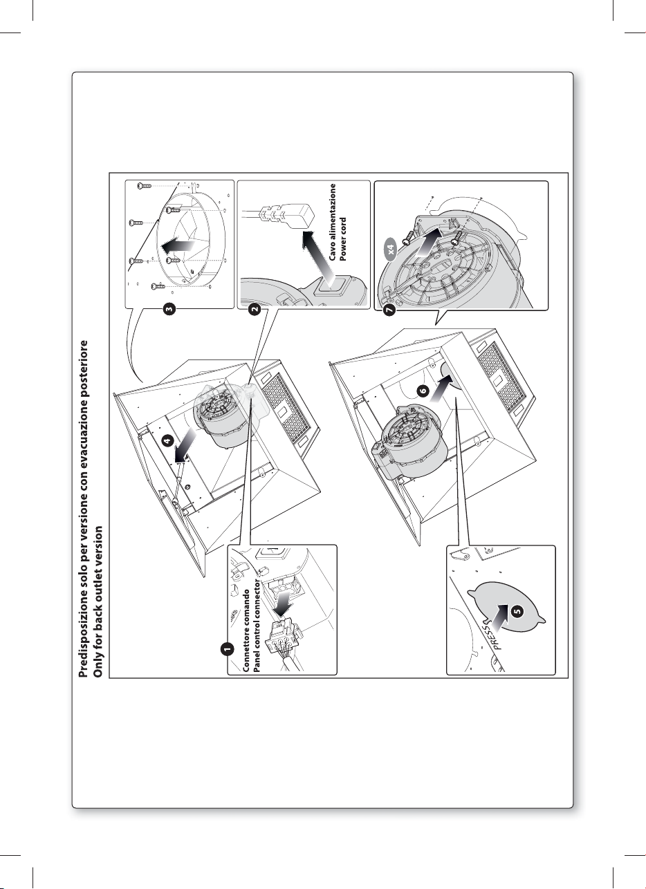
CAPPA DI VERSIONE
AD EVACUAZIONE ESTERNA (aspirante)
In questa versione i fumi e i vapori della cucina vengono convogliati verso l’esterno attraverso
un tubo di scarico.
Il convogliatore di scarico che sporge sulla parte superiore della cappa deve essere collegato
con un tubo che conduce i fumi e i vapori in una uscita esterna. In questa versione vanno tolti
i filtri al carbone attivo se esistenti; per l’estrazione vedere istruzioni al punto F. Quando la
cappa da cucina viene utilizzata contemporaneamente ad altri apparecchi che impiegano gas
o altri combustibili, il locale deve disporre di sufficiente ventilazione secondo le norme vigenti.
Deviazione per la Germania:
Quando la cappa da cucina e apparecchi alimentati con energia diversa da quella elettrica
sono in funzione simultaneamente, la pressione negativa nel locale non deve superare i 4
Pa (4 x 10⁻⁵ bar).
9
Page 12

F
CAPPA DI VERSIONE A RICICLO INTERNO (filtrante)
In questa versione l’aria passa attraverso i filtri di carbone attivo per essere purificata e viene
riciclata nell’ambiente cucina.
Controllare che i filtri al carbone attivo siano montati sul motore, in caso negativo applicarli
come indicato nelle istruzioni al punto H.
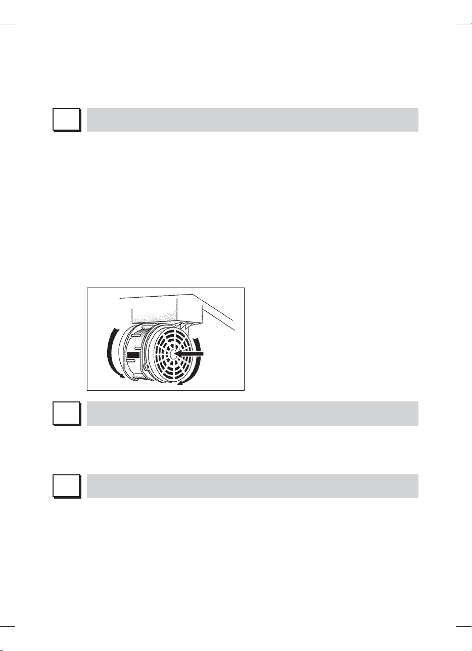
Se la cappa viene predisposta in versione filtrante rimuovere la valvola di non ritorno montata
sul raccordo di uscita del motore.
Per il miglior rendimento si consiglia di utilizzare la terza velocità in presenza di forti odori
e vapori, la seconda velocità nelle condizioni normali, la prima velocità per mantenere l’aria
pulita con bassi consumi di energia elettrica. Si consiglia di mettere in funzione la cappa
quando si inizia a cuocere e manteneria in funzione fino alla scomparsa degli odori.
G
FUNZIONAMENTO
PULSANTIERA ELETTRONICA
1: Timer/Allarme filtri
La luce fissa ROSSA sta ad indicare l’allarme filtro grassi attivato (dopo 30 ore), per disat-
tivare questo allarme ed azzerare i contatori tenere premuto il tasto per 3 secondi.
Luce ROSSA lampeggiante sta ad indicare che la funzione timer è attiva. Tale funzione è
attivabile solo se alla pressione del tasto (prolungata o meno) il motore è già attivo ad una
velocità qualsiasi. Tale funzione determina l’autospegnimento della cappa dopo 7 minuti.
Con la funzione Timer attiva, la cappa può essere in ogni caso spenta dall’utente e la fun-
zione verrà disattivata. La funzione Timer rimane associata ad una velocità. Il cambio della
velocità, con la funzione timer attiva, implica la disattivazione di quest’ultima.
2: 1° Velocità
Nella situazione di LED spento, la pressione non prolungata del tasto implica l’accensione
della cappa al la 1° velocità e l’accensione del relativo LED. La funzione si attiverà al rilascio del tasto.
Nella situazione di LED spento ed un’altra velocità attiva, la pressione del tasto implica la
selezione della 1° velocità, l’accensione del relativo LED e lo spegnimento del LED asso-
ciato alla velocità precedentemente selezionata.
A LED accesso la pressione del tasto implica lo spegnimento del LED e del MOTORE.
A LED spento la pressione prolungata (almeno 3sec) del tasto implica l’attivazione della
funzione ricircolo. Durante la funzione ricircolo (della durata 24 ore), il LED lampeggia.
Dall’attivazione di tale funzione, la cappa resta accesa per 1 ora alla 1° velocità, poi si
ferma per 3 ore e si riattiva per un’altra ora. Tali cicli vengono ripetuti fino al timeout.
Con questa funzione attivata non si possono selezionare le altre velocità. Per Togliere
questa funzione, tenere premuto per almeno 3 secondi il tasto 2.
3: 2° Velocità
Nella situazione di LED spento ed un’altra velocità attiva, la pressione del tasto (pro-
lungata o meno) implica la selezione della 2° velocità, l’accensione del relativo LED e lo
spegnimento del LED associato alla velocità precedentemente selezionata.
10
Page 13

Nella situazione di LED spento e nessuna velocità attiva, la pressione del tasto non ha
effetto.
A LED accesso la pressione del tasto3 non ha effetti.
Per spegnere la cappa occorre selezionare prima la 1° velocità, poi premere nuovamente
tale tasto.
4: 3° Velocità
Nella situazione di LED spento ed un’altra velocità attiva, la pressione del tasto (pro-
lungata o meno) implica la selezione della 3° velocità, l’accensione del relativo LED e lo
spegnimento del LED associato alla velocità precedentemente selezionata.
Nella situazione di LED spento e nessuna velocità attiva, la pressione del tasto non ha
effetto.
A LED accesso la pressione del tasto4 non ha effetti.
Per spegnere la cappa occorre selezionare prima la 1° velocità, poi premere nuovamente
tale tasto.
5: 4° Velocità
Nella situazione di LED spento ed un’altra velocità attiva, la pressione(prolungata o meno)
del tasto implica la selezione della 4° velocità, l’accensione del relativo LED e lo spegni-
mento del LED associato alla velocità precedentemente selezionata.
Nella situazione di LED spento e nessuna velocità attiva, la pressione del tasto non ha
effetto.
A LED accesso la pressione del tasto5 non ha effetti.
La quarta velocità deve restare accesa per massimo 7 minuti, dopo di che si deve ritor-
nare alla terza.
Per spegnere la cappa occorre selezionare prima la 1° velocità, poi premere nuovamente
tale tasto.
6: Luce
La pressione breve del tasto T6 accende e spegne la luce. Il tasto T6 si illumina se la luce
è accesa.
Gestione della pressione dei tasti:
Pressione prolungata = dito presente sul tasto per almeno 3 secondi, la funzione si attiva
durante la pressione.
Pressione non prolungata = dito presente sul tasto per meno di 3 secondi, la funzione di
attiva al rilascio.
Italiano
H
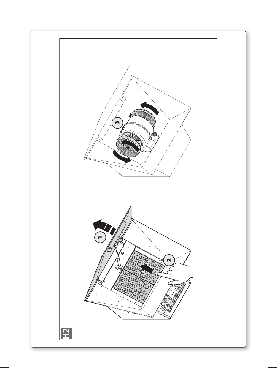
FILTRI ISTRUZIONI PER L’ESTRAZIONE E LA SOSTITUZIONE
1. FILTRI METALLICI
Per rimuovere il filtro metallico antigrasso, aprire il pannello in vetro frontale e poi
agire sulla maniglia (vedi fig. H1).
2. FILTRI AL CARBONE ATTIVO
Rimuovere i filtri metallici secondo le indicazioni del paragrafo H1.
A questo punto si accede facilmente ai due filtri che sono agganciati sul lato dx e sx del
convogliatore. Per il montaggio/sostituzione vedi figura H2.
Per ordinare i nuovi filtri carbone rivolgersi al distributore/rivenditore.
SOLO PER ITALIA: Scaricare l’apposito modulo ordine filtro sul sito:
www.falmec.com (accedere sul menù a tendina assistenza).
11
Page 14

ILLUMINAZIONE
I
FARETTO LED
In questo caso la cappa è dotata di illuminazione di faretti led ad alta efficienza, basso consumo e durata molto elevata in condizioni di normale utilizzo.
L
Una costante manutenzione garantisce un buon funzionamento ed un buon rendimento nel
MANUTENZIONE E PULIZIA
tempo. Particolari attenzioni vanno rivolte ai filtri metallici antigrasso ed ai filtri al carbone
attivo, infatti la pulizia frequente dei filtri e dei loro supporti garantisce che sulla cappa non si
accumulino grassi che sono pericolosi per la facilità di incendio.
1. FILTRI ANTIGRASSO METALLICI E VASCHETTA RACCOGLI OLIO
Hanno la funzione di trattenere le particelle grasse in sospensione, pertanto si consiglia di
lavarli ogni mese in acqua calda e detersivo evitando di piegarli. Attendere che siano ben
asciutti prima di rimontarli.
2. FILTRI AL CARBONE ATTIVO
Hanno la funzione di trattenere gli odori presenti nel flusso d’aria che li attraversa. L’aria
depurata per successivi passaggi attraverso i filtri viene rimessa nell’ambiente cucina. l
filtri al carbone attivo non possono essere lavati e vanno sostituiti mediamente ogni 3-4
mesi (dipende poi dall’uso). Per la sostituzione dei filtri al carbone attivo seguire le istru-
zioni come al punto H2.
3. PULIZIA ESTERNA
Si raccomanda di pulire le superfici esterne delle cappe almeno ogni 15 giorni per evitare
che le sostanze oleose o grasse possano intaccare le superfici in acciaio.
La pulizia della cappa va eseguita usando un panno umido con detersivo liquido neutro o
con alcool denaturato.
Nel caso di materiale con trattamento antimpronta (Fasteel) eseguire la pulizia solo con
acqua e sapone neutro utilizzando un panno morbido avendo cura di risciacquare e
asciugare accuratamente. Non si devono utilizzare prodotti contenenti sostanza abrasive,
panni con superfici ruvide o panni comunemente in commercio per la pulizia dell’acciaio.
L’utilizzo di sostanze abrasive e panni ruvidi danneggerà irreparabilmente il trattamento
superficiale dell’acciaio.
Conseguenza diretta del non rispetto di tali avvertenze sarà il deterioramento irreversibile
della superficie dell’acciaio.
Tali avvertenze dovranno essere conservate insieme al libretto istruzioni della cappa.
Il produttore declina ogni responsabilità qualora non vengano rispettate tali istruzioni.
4. PULIZIA INTERNA
É vietata la pulizia di parti elettriche o parti relative al moto re all’interno della cappa, con
12
Page 15
liquidi o solventi;
Effettuare tutte queste operazioni scollegando preven tivamente l’apparecchio dalla rete
Non usare prodotti contenenti abrasivi.
elettrica.
Italiano
M
La sua nuova apparecchiatura è coperta da garanzia. Le condizioni di garanzia sono riportate
N
GARANZIA
per esteso sull’ulti ma pagina di copertina di questo libretto.
La casa costruttrice non risponde delle possibili ine sattezze, imputabili ad errori di stampa
o di trascrizio ne, contenute nel presente libretto. Si riserva di appor tare ai propri prodotti
quelle modifiche che ritenesse necessarie o utili, anche nell’interesse dell’utenza, senza
pregiudicare le caratteristiche essenziali di fun zionalità e di sicurezza.
ISTRUZIONI MONTAGGIO CAPPA
AVVERTENZA: L’installazione di viti o dispositivi di fissaggio non in conformità con le presenti
istruzioni può comportare pericolo di folgorazione.
Fase 1
- Appoggiare alla parete la barra di sostegno (A-fig. 02), ad un’altezza dal piano cottura de-
terminata
dalla somma delle quote X+374 mm.
- Controllare con una bolla di livello l’allineamento orizzontale e segnare alle estremità della
barra n° 2 punti di foratura.
- Forare, inserire n° 2 tasselli ad espansione ø 8mm e fissare la barra con le relative viti.
Fase 2
-Agganciare la cappa alla barra di sostegno (fig. 03).
- Aprire il pannello in vetro frontale e rimuovere i filtri metallici.
- Regolare l’allineamento della cappa tramite le viti delle attaccaglie (fig. 03). La vite superiore
(B) regola la distanza dalla parete, quella inferiore (C) lo scorrimento verticale.
Fase 3
- Per evitare lo sganciamento della cappa dovuto ad una pressione sottostante, fissarla alla
parete con un tassello ad espansione e relativa vite utilizzando le apposite staffe “S” presenti sulla parte superiore della cappa (fig. 04).
- Nel caso di versione aspirante collegare il raccordo di uscita del ventilatore (uscita superiore
o sul retro) allo scarico esterno mediante idonea tubazione (fig. 05).
- Eseguire il collegamento elettrico solo dopo aver disinserito l’alimentazione elettrica della
cappa.
Fase 4 (optional) (fig. 06)
- Inserire la prolunga (H) nel camino (G) e fissare l’assieme al corpo cappa mediante le viti (V2).
- Fare scorrere la prolunga (H) fino a raggiungere l’altezza desiderata.
- Trovata la posizione ottimale, appoggiare alla parete la staffa (L), controllare con una bolla di
livello l’allineamento orizzontale e segnare alle estremità n°2 punti di foratura.
- Forare, inserire n° 2 tasselli ad espansione ø 4mm e fissare la staffa (L) con le relative viti.
- Avvitare con le viti (M) la prolunga (H) alla staffa (L).
Fase 5
- Rimontare sulla cappa i filtri metallici e chiudere il pannello in vetro frontale.
- Alimentare elettricamente la cappa rispettando le norme vigenti (sez. D).
13
13
Page 16

GB
INSTRUCTIONS BOOKLET
A
WARNINGS
This instruction booklet must be kept together with the appliance for future reference. If the
appliance is sold or consigned to other parties, check that the booklet is supplied with it, to
ensure that the new user has the correct information on the operation of the range hood and
is aware of the warnings. These warnings have been provided for the your safety and the
safety of others. As a result, please read them carefully before installing and operating the
appliance.
This appliance is not intended for use by persons (including children) with reduced physical,
sensory or mental capabilities, or lack of experience and knowledge, unless they have been
given supervision or instruction concerning use of the appliance by a person responsible for
their safety.
Children should be supervised to ensure that they do not play with the appliance.
The appliance must be installed by qualified personnel, in accordance with the standards in
force. If the supply cord is damaged, it must be re-placed by the manufacturer, its service
agent or similarly qualified persons in order to avoid a hazard. Any modifications that may be
required to the electrical system for the installation of the range hood must only be made by
qualified electricians.
It is dangerous to modify or attempt to modify the characteristics of this system. In the event of
malfunctions or if repairs are required to the appliance, do not attempt to solve the problems
directly.
Repairs performed by unqualified persons may cause damage. For all repair and other work on
the appliance, contact an authorised service/spare parts centre.
Always check that all the electrical parts (lights, exhaust device), are off when the appliance
is not being used. Read the entire instruction booklet before performing any operations on the
range hood.
The range hood must only be used for the exhaust of cooking fumes in home kitchens. The
manufacturer disclaims all liability for any other use of the appliance.
The maximum weight of any object placed above the hood, or hung to it (if possible) must
not exceed 1,5 kilos. After installing the stainless steel hood, clean it in order to remove any
residue of the protective glue, and stains of grease or oil. The manufacturer recommends its
cleaning cloth available for purchase. The manufacturer accepts no liability in case of damage caused by the use of different detergent types.
SAFETY WARNINGS
The electrical system features an earth connection in compliance with international safety
standards; furthermore, it is compliant with the European standard for electromagnetic com-
Do not connect the appliance to flues (from boilers, fireplaces, etc.). Make sure the mains
Check deep-fryers during use: superheated oil may be flammable.
patibility.
voltage corresponds to the values on the rating plate located inside the range hood.
- Ensure there is adequate ventilation of the room when the rangehood is used at the same
time as appliances burning gas or other fuels.
- Do not flambe under the rangehood
- The exhaust air must not be discharged into a flue which is used for exhausting fumes from
appliances burning gas or other fuels.
- Ensure that all regulations concerning the discharge of exhaust air have been fulfilled before
you use the appliance.
14
Page 17
Before performing any cleaning or maintenance operations, disconnect the appliance by un-
plugging it or using the main switch. The manufacturer disclaims all liability for any damage
that may be directly or indirectly caused to people, things and animals due to the failure to
follow all the instructions provided in this booklet and above all the warnings relating to the
installation, operation and maintenance of the appliance.
- there is a fire risk if cleaning is not carried out in accordance with the instructions.
CAUTION: Accessible parts may become hot when used with cooking appliances.
- Max. length screw for fixing the chimney is 10 mm (provided by the manufacturer).
WARNING: Failure to install the screws or fixing device in accordance with these instructions
may result in electrical hazards.
Warning only for Australia: hood width less than 90 cm: use max. 4 hobs
CAUTION:
This product must be disposed of at end of life according to the rules in force.
B
TECHNICAL SPECIFICATIONS
The technical data pertaining to the electric appliance The technical specifications of the appliance are shown on the rating plates located inside the range hood.
English
C
D
INSTALLATION
(Section reserved for qualified installers of the range hood)
Minimum distance: distance between the highest part of the cooker and the lowest part of the
hood. Generally, when the hood is placed on gas cookers, this distance must be at least of 65
cm (see figure 02). However, according to an interpretation of standard EN60335-2-31 dated
11-07-2002 of TC61 (sub-clause 7.12.1 meeting 15 agenda item 10.11), the minimum distance
between the cooker and the lower part of this hood can be reduced to 53 cm. Should the
instructions for the gas cooker specify a greater distance, take this into consideration.
In the exhaust version, the diameter of the fume discharge duct must not be smaller than the
hood connection. In the horizontal sections, the duct must slope slightly (around 10%) upwards
to better convey the air outside the room.
Reduce bends to a minimum and make sure the pipes feature the minimum required length.
Comply with the current regulations applying to air discharge into the atmosphere. If other appliances that use gas or other fuels are being used at the same time (boiler, stove, fireplaces,
etc.), make sure the room where the fumes are extracted is well ventilated, in compliance with
the current regulations. Assembly instructions: see section “O” of this manual.
ELECTRICAL CONNECTIONS
(Section reserved for qualified installers)
WARNING!
Before doing any work inside the range hood, disconnect the appliance from the mains
power supply. Check that the wires inside the range hood are not disconnected or cut; if
this is the case, contact your nearest service centre. The electrical connections must be
performed by qualified personnel.
The connections must be performed in compliance with the legal standards in force. Check
that the relief valve and the electrical system are able to support the load of the appliance (see
the technical specifications in point B).
Some types of appliance are supplied with a cable without plug; in this case, “standardised”
plugs must be used, keeping in mind that:
Page 18

- the yellow-green wire must be used for the earth,
- the blue/white wire must be used for the neutral,
- the brown/black wire must be used for the phase; the cable must not come into contact with
hot parts (over 70° C).
- fit a plug that is suitable for the load to the power cable, and connect it to a suitable power
outlet.
For appliances that come supplied with cable and plug please ensure they are plugged into a
circuit suitable for this appliance.
Please refer to a qualifed person. (See technical specifications in point B).
The manufacturer declines all liability if the safety standards are not observed.
E
G
RANGE HOOD WITH OUTSIDE DISCHARGE (exhaust)
In this version, the fumes and steam from the kitchen are conveyed outside through an exhaust
duct. The exhaust conveyor that protrudes from the upper part of the range hood must be connected to a duct that carries the fumes and steam outside. In this version, the charcoal filters,
if fitted, should be removed; to do this, see the instructions in point F. There must be adequate
ventilation of the room when the range hood is used at the same time as appliances burning
gas or other fuels, according to the standard.
Deviation for Germany:
When the range hood and appliances supplied with energy other than electricity are simultaneously in operation, the negative pressure in the room must not exceed 4 Pa (4x10 E-5 bar).
F
RECIRCULATING RANGE HOOD (with filter)
In this version, the air passes through charcoal filters for purification, and is then recirculated
back into the kitchen.
Check that the charcoal filters are fitted to the motor, and if not, install them as described in
the instructions in point H.
If the hood is of filtering type, remove the non-return valve fitted at the motor’s outlet.
For maximum efficiency, the third speed should be used when there are strong odours or a lot
of steam, the second speed in normal conditions, and the first speed for keeping the air clean
with minimum energy consumption. The range hood should be switched on when starting to
cook, and left on until the odours disappear.
OPERATION
16
ELECTRONIC CONTROL PANEL
1: Timer/Alarm filters
The steady RED light indicates that the fat filter alarm is activated (after 30 hours), to de-
activate this alarm and zero the meters, maintain the Key pressed for 3 seconds.
Flashing RED light indicates that the timer function is activated. This function can only be
activated if the motor is activated and running at any velocity when the Key is pressed
(either prolonged or not). This function will cause the automatic switch-off of the hood
after 7 minutes.
Page 19

With the Timer function activated, the hood can be switched-off by the operator in any
case and the function will be deactivated.
The Timer function remains associated to a velocity. A change in the velocity, with the
Timer function activated, will deactivate it.
2: 1st Velocity
When the LED is switched-off, non-prolonged pressing of the key will switch-on the hood
at the 1st velocity and illuminate the respective LED. The function will switch-on when the
Key is released.
When the LED is switched-off and another velocity is activated, pressing the Key will
imply selection of the 1st velocity, switching-on of the respective LED and switching-off of
the LED associated with the velocity that was previously selected.
When the LED is on, pressing the Key will imply the switching-off the LED and MOTOR.
When the LED is switched-off, prolonged pressing (at least 3 seconds) of the Key will
cause activation of the recirculation function. During the recirculation function (with a
duration of 24 hours), the LED will flash. From the activation of this function, the hood will
remain switched-on for one hour at the 1st velocity, after which it will switch-off for 3 hours
and then reactivate for another hour. These cycles are repeated until the timeout.
With this function activated, the other functions cannot be selected. To remove this func-
tion, keep Key 2 pressed for at least 3 seconds.
3: 2nd Velocity
When the LED is switched-off and another velocity activated, pressing the Key (either
prolonged or not) will imply the selection of the 2nd velocity, switching-on of the respec-
tive LED and switching-off of the LED associated with the velocity that was previously
selected.
When the LED is switched-off and no velocity activated, pressing the Key will have no
effect.
When the LED is switched-on, pressing the Key 3 will have no effect.
To switch the hood off, it will be necessary to firstly select the 1st velocity and then repress
the same Key.
4: 3rd Velocity
When the LED is switched-off and another velocity activated, pressing the Key (either
prolonged or not) implies the selection of the 3rd velocity, the switching-on of the re-
spective LED and switching-off of the LED associated to the velocity that was previously
selected.
When the LED is switched-off and no velocity activated, pressing the Key will have no
effect.
When the LED is switched-on, pressing the Key 4 will have no effect.
To switch the hood off, it will be necessary to firstly select the 1st velocity and then repress
the same Key.
5: 4th Velocity
When the LED is switched-off and another velocity activated, pressing the Key (either
prolonged or not) implies the selection of the 4th velocity, switching-on of the respective
LED and switching-off of the LED associated to the velocity that was previously selected.
When the LED is switched-off and no velocity activated, pressing the Key will have no
effect.
When the LED is switched-on, pressing the key 5 will have no effect.
The forth velocity must remain on for a maximum of 7 minutes, after which, one must
return to the third.
To switch the hood off, it will be necessary to firstly select the 1st velocity and then repress
the same key.
6: Light
Briefly pressing key T6 will turn the light on and off. The T6 key will light up if the light is on.
English
17
Page 20
Key pressure management:
Prolonged pressure = finger pressed on key for at least 3 seconds, the function activates
during pressure.
Non-prolonged pressure = finger pressed on key for less than 3 seconds, the function
activates upon its release.
H
FILTERS INSTRUCTIONS FOR REMOVAL AND REPLACEMENT
1. METAL FILTERS
Open the front glass panel to open the anti-grease metal filter and
adjust the handle (see fig. H1).
2. ACTIVATED CARBON FILTERS
Remove the metal filters by following the instructions in paragraph H1.
The two filters attached to the right and left side of the conveyor can now be easily ac-
cessed.
See figure H2 for assembly/replacement.
To order new carbon filters contact your distributor/dealer.
ONLY FOR ITALY: Download the form to order the filter from the website:
www.falmec.com (via the dropdown assistance menu).
LIGHTING
I
LED SPOTLIGHT
In this case the hood is equipped with high efficiency, low power LED spotlights with extremely
high durability under normal use conditions.
L
Constant maintenance ensures the correct operation and efficiency of the appliance over
MAINTENANCE AND CLEANING
time. Special attention should be paid to the metal grease-trapping filters and the charcoal
filters. Frequent cleaning of the filters and their supports will ensure that fats and grease do
not accumulate on the range hood, with the consequent risk of fire.
1. METAL ANTI-GREASE FILTERS AND GREASE DRIP TRAY
Their function is to trap suspended grease particles, accordingly, it is advisable to wash
them once a month in hot water and detergent, without bending them. Leave to dry
completely before re-assembling them.
18
Page 21
2. CHARCOAL FILTERS
These trap the odours present in the stream of air that passes through them. The air is puri-
fied by passing a number of times through the filters and being recirculated into the kitchen.
The charcoal filters cannot be cleaned, and should be replaced on average every 3-4 months
(according to use). To replace the charcoal filters, see the instructions in point H2.
3. CLEANING THE OUTSIDE OF THE APPLIANCE
It is advised to clean the external hood surfaces at least every 15 days in order to avoid that
oily or greasy substances affect the steel surfaces.
The ouside of the range hhod should be cleaned using a damp cloth and neutral liquid
detergent or denatured alcohol.
In case of fingerprint-less finish (fasteel) clean only with water and neutral soap using
clean with a soft cloth, rinse and wipe dry thoroughly. Do not use products that contain
abrasive substances, rough cloths or cloths specifically designed for cleaning steel. Using
abrasive substances or rough cloths will inevitably damage the finish of steel. The steel
surface will be irrevocably damaged if the instructions above are not complied with. Keep
these instructions together with the instructions for use of your hood.
The manufacturer accepts no liability for any damage caused by non-compliance with the
instructions above.
4. CLEANING THE INSIDE OF THE APPLIANCE
The electrical parts or parts of the motor assembly inside the range hood must not be
cleaned using liquids or solvents.
Do not use abrasive products.
All the above operations must be performed after having disconnected the appliance from the
mains power supply.
English
M
The new equipment is covered by warranty.
The warranty conditions are provided by the distributor.
N
WARRANTY
The manufacturer is not liable for any inaccuracies in this booklet resulting from printing or
transcription errors. The manufacturer reserves the right to modify its products as it considers necessary or in the interests of the user, without compromising their essential safety and
operating characteristics.
HOOD ASSEMBLY INSTRUCTIONS
WARNING: Failure to install the screws or fixing device in accordance with these instructions
may result in an electric shock hazard.
Phase 1
- Place the support bar (A-fig. 02) on the wall at a determined height from the cooker
by the sum of the heights X+374 mm.
- Use a spirit level to check the horizontal alignment and draw 2 marks at each end of the bar,
this is where the holes will be drilled.
- Drill the holes, insert 2 ø 8mm expansion bolts and fasten the bar with the relative screws.
Phase 2
- Hook the hood onto the support bar (fig. 03).
- Open the front glass panel and remove the metal filters.
- Adjust the alignment of the hood, using the fixing screws (Fig. 03). The upper screw (B)
adjusts the distance from the wall, the lower one (C) the vertical scrolling.
19
Page 22

Phase 3
- To prevent the hood from falling due to pressure below, fasten it to the wall with an expansion
plug and relative screw using the appropriate brackets “S” on the top of the hood (fig. 04).
- For the exhaust version, connect the output fitting of the fan (upper output or on rear) to the
external discharge with a suitable pipe (fig. 05).
- Set up the electric connection only after disconnecting the power supply of the
hood.
Phase 4 (optional) (fig. O5)
- Place extension (H) in the flue (G) and fasten this assembly to the body of the hood using the
screws (V2).
- Slide the extension (H) until it is positioned at the desired height.
- Once you have found the best position, lean the bracket (L) on the wall, verify the horizontal
alignment with a spirit level and mark 2 drilling points at the ends.
- Drill the holes, insert 2 expansion bolts of 4mm ø and fasten the bracket (L) with the relative
screws.
- Tighten the extension (H) to the bracket (L) using screws (M).
Phase 5
- Remount the hood, metal filters, and close the front glass panel.
- Power on the hood in accordance with current regulations (sec. D).
20
Page 23

D
BEDIENUNGSANLEITUNG
A
Sollte das Gerät verkauft bzw. einer anderen Person übergeben werden, muss die Bedie-
Diese Hinweise sind für Ihre Sicherheit und die anderer Personen abgefasst worden. Daher
HINWEISE
Diese Bedienungsanleitung muss unbedingt zusammen mit dem Gerät aufbewahrt werden, um
in Zukunft nachgeschlagen werden zu können.
nungsanleitung unbedingt mitgeliefert werden, damit der neue Benutzer mit dem Betrieb der
Dunstabzugshaube und den diesbezüglichen Hinweisen vertraut werden kann.
sollten Sie die Bedienungsanleitung vor der Installation und Verwendung des Gerätes aufmerksam durchlesen.
Dette apparat er ikke beregnet til brug af personer (herunder børn) med nedsatte fysiske, sensoriske eller mentale evner, eller manglende erfaring og viden, medmindre de er blevet vejledt eller
instrueret i brugen af apparatet af en person med ansvar for deres sikkerhed.
Børn skal være under opsyn for at sikre, at de ikke leger med apparatet.
Die Installation hat den geltenden Vorschriften gemäß von kompetenten, qualifizierten Installateuren durchgeführt zu werden.
Beschädigte Speisekabel sind vom Hersteller bzw. von dessen Kundenservice bzw. von einer
Person mit ähnlicher Qualifikation auszuwechseln, um Gefahren vorzubeugen.
Eventuelle erforderliche Änderungen, die für die Installation der Dunstabzugshaube an der
elektrischen Anlage durchgeführt werden müssen, dürfen ausschließlich von kompetenten
Personen vorgenommen werden.
Es ist gefährlich, die Eigenschaften dieser Anlage abzuändern bzw. versuchen abzuändern. Bei
Reparaturen bzw. Betriebsstörungen des Gerätes nicht versuchen, das Problem alleine zu lösen.
Die Reparaturen, die von nicht kompetenten Personen durchgeführt werden, können Schäden
verursachen.
Sich für eventuelle Eingriffe an einen zugelassenen Kundenservice, der über die geeigneten
Ersatzteile verfügt, wenden.
Wenn das Gerät nicht benutzt wird, müssen alle elektrischen Teile (Beleuchtung, Absaugvorrichtung) ausgeschaltet sein. Vor Durchführung von Arbeitsvorgängen an der Dunstabzugshaube die Bedienungsanleitung lesen.
Die Dunstabzugshaube darf ausschließlich zum Absaugen des Dampfes, der beim Kochen in
einer Haushaltsküche entsteht, verwendet werden.
Bei anderen Einsätzen wird der Hersteller von jeder Haftung befreit.
Das Gesamtgewicht von Gegenständen, die eventuell auf die Dunstabzugshaube positioniert
bzw. an diese gehängt werden (falls vorgesehen), darf höchstens 1,5 Kg betragen.
Nach der Installation von Edelstahlhauben muss man diese reinigen, um Schutzkleberreste
und eventuelle Fett- und Ölflecken zu entfernen.
Der Hersteller empfiehlt für doesen Arbeitsvorgang die Verwendung der mitgelieferten Reinigungstücher.
Die Verwendung anderer Reinigungsmittel befreit den Hersteller von jeder Haftung für eventuelle auf deren Benutzung zurückzuführende Schäden.
Deutsch
Das Gerät auf keinen Fall an die Ablassleitungen von Rauch, das durch Verbrennung entsteht
SICHERHEITSBESTIMMUNGEN
Die elektrische Anlage ist mit einer Erdung ausgestattet, die den internationalen Sicherhei-
tsvorschriften entspricht; sie erfüllt außerdem die europäischen Entstörungsvorschriften.
(Heizkessel, Kamine, usw...), anschließen. Sich vergewissern, dass die Netzspannung mit den
im Inneren der Dunstabzugshaube angegebenen Daten übereinstimmt.
21
Page 24

Die Friteusen während der Benutzung kontrollieren: das überhitzte Öl könnte sich entzünden.
Für eine ausreichende Lüftung im Raum sorgen, wenn die Dunstabzugshaube zusammen mit
- Kein offenes Feuer unter der Haube anzünden.
- Das Gerät auf keinen Fall an die Ablassleitungen von Rauch, das durch Verbrennung entsteht
- Sich vergewissern, dass alle gelten Vorschriften bezüglich der Luftablasses außerhalb des
anderen Geräten, die mit Brennstoffen und ähnlichen Stoffen arbeiten, verwendet wird.
(Heizkessel, Kamine, usw...), anschließen.
Raumes erfüllt werden, bevor man die Dunstabzugshaube benutzt.
Vor Durchführung von Reinigungs- oder Wartungsarbeiten muss man die Stromversorgung
unterbrechen, indem man den Stecker zieht bzw. den Hauptschalter betätigt. Der Hersteller
lehnt jede Haftung für eventuelle direkte oder indirekte Schäden an Personen, Gegenständen
und Haustieren ab, die auf die Nichteinhaltung der in der vorliegenden Bedienungsanleitung
enthaltenen Vorschriften zurückzuführen sind und insbesondere die Installation, Bedienung
und Wartung des Gerätes betreffen.
- Wenn die Reinigung nicht entsprechend den Anweisungen erfolgt, besteht Brandgefahr.
VORSICHT: Erreichbare Bauteile könnten sich erhitzen, wenn sie Kochgeräten verwendet
werden.
- Die max. Länge der Schrauben zur Befestigung des Rauchfangs beträgt 10 mm (vom Hersteller gestellt).
WARNUNG: Erfolgt die Installation der Schrauben oder Befestigungsvorrichtungen nicht
entsprechend den vorliegenden Anweisungen, führt dies zu Gefahr durch Stromschlag.
ADVARSEL:
Dette produkt skal bortskaffes efter endt levetid i henhold til de gældende regler.
B
C
TECHNISCHE MERKMALE
Die technischen Daten des Elektrogeräts sind an den Typenschildern im Innern der Dunstabzugshaube angegeben.
INSTALLATION
(dieser Abschnitt ist dem für die Montage der Haube qualifizierten Personal vorbehalten)
Mindestabstand: Abstand zwischen dem höchsten Teil des Kochgeräts und dem untersten
Teil der Abzugshaube. Wenn die Abzugshaube über einem Gaskochgerät positioniert ist, muss
dieser Abstand gewöhnlich mindestens 65 cm betragen (siehe Abbildung 02). Jedenfalls kann
gemäß der Auslegung der Norm EN60335-2-31 vom 11-07-2002 vonseiten der TC61 (subclause 7.12.1 meeting 15 agenda item 10.11) im Falle dieser Abzugshaube der Mindestabstand
zwischen der Kochebene und dem unteren Teil der Abzugshaube auf 53 cm vermindert werden. Wenn die Anleitung der Gaskochebene einen größeren Abstand vorschreibt, muss dies
eingehalten werden.
Bei der Abluftversion muss der Durchmesser des gesamten Abzugsrohrs mindestens dem des
Anschlusses der Abzugshaube entsprechen. In den waagrechten Abschnitten muss das Rohr
leicht nach oben geneigt sein (ca. 10 %), um die Luft besser aus dem Rraum zu leiten.
Die Kurven auf ein Minimum reduzieren und prüfen, ob alle Rohre die erforderliche Mindestlänge aufweisen.
Die geltenden Vorschriften bezüglich des Luftablasses nach draußen beachten. Bei gleichzeitiger Verwendung anderer mit Gas oder anderen Brennstoffen gespeister Verbraucher
(Heizkessel, Öfen, Kamine, etc.) für eine angemessene, vorschriftsmäßige Lüftung des Raumes sorgen, in dem die Rauchabsaugung erfolgt. Montageanleitung: siehe Abschnitt “O” im
vorliegendem Handbuch
22
Page 25

D
ELEKTRISCHER ANSCHLUSS
(Dieser Abschnitt ist Fachpersonal mit der für den Stromanschluss erforderlichen Qualifikation vorbehalten)
ACHTUNG! Vor jedem Eingriff im Innern der Haube muss das Gerät vom Stromnetz getrennt werden. Sicherstellen, dass die Stromkabel im Innern der Dunstabzugshaube nicht
abgeklemmt oder durchgeschnitten werden; sollte dies dennoch vorkommen, den nächst
gelegenen Kundendienst kontaktieren.
Der Anschluss muss unter Befolgung der gültigen Rechtsvorschriften erfolgen. Sicherstellen,
dass das Reduzierventil und die Elektroanlage der Geräteleistung entsprechen (siehe technische Spezifikationen in Punkt B). Einige Gerätetypen können mit einem Kabel ohne Stecker
ausgestattet sein, in diesem Fall ist ein „genormter“ Stecker zu verwenden, wobei folgendes
zu beachten ist:
- Der gelb/grüne Draht ist für die Erdung zu benutzen;
- der blaue Draht ist für den Nullleiter, und
- der braune Draht für die Phase bestimmt. Das Kabel darf auf keinen Fall mit heißen Teilen in
Berührung kommen (über 70° C).
- Am Netzkabel einen der Geräteleistung entsprechenden Stecker anbringen und diesen in
eine Sicherheits- Steckdose stecken.
Bei Geräten, die mit Kabel und Stecker ausgestattet geliefert werden, muss man sicherstellen,
dass sie mit einem geeigneten Kreislauf verbunden werden. Sich an eine qualifizierte Person
wenden (siehe technische Spezifikationen in Punkt B).
Die Herstellerfirma ist nicht haftbar, wenn die Unfallverhütungsvorschriften nicht eingehalten werden.
Deutsch
E
F
HAUBE MIT ABLUFTBETRIEB (absaugend)
Bei dieser Ausführung wird der während des Kochens entstehende Dampf durch ein Abzugsrohr nach außen abgeführt. Der sich oberhalb der Haube befindliche Rauchzug ist an ein
Abzugsrohr anzuschließen, über das Rauch und Dampf zu einem Auslass ins Freie geleitet
werden. Bei dieser Ausführung sind eventuell vorhandene Aktivkohlefilter wie in Punkt F
beschrieben zu entfernen. Wenn die Dunstabzugshaube gleichzeitig mit anderen Geräten benutzt wird, die mit Gas oder anderen Brennstoffen betrieben werden, muss eine ausreichende
Belüftung des Raums gesorgt werden.
Germany (Feuerungsverordnung vom 31-01-1986 und DVGW-TRGI 1986, Amtsblatt G 600):
Bei gleichzeitigem Betrieb der Dunstabzugshau-be im Abluftbetrieb und Feuerstätten darf im
Aufstellraum der Feuerstätte der Unterdruck nicht größer als 4 Pa (4 x 10⁻⁵ bar) sein.
HAUBE MIT UMLUFTBETRIEB (filtrierend)
Bei dieser Ausführung strömt die Luft durch Aktivkohlefilter, wo sie gefiltert und erneut an
den Raum abgegeben wird. Sicherstellen, dass die Aktivkohlefilter am Motor installiert sind,
andernfalls müssen sie wie unter Punkt H beschrieben installiert werden.
Bei Dunstabzugshauben im Umluftbetrieb empfehlen wir die Rückstauklappe, die am Ausgangsverbindungsstück des Motors montiert ist, zu entfernen.
Für optimale Leistung ist es ratsam, bei starker Geruch- und Dampfbildung die dritte Drehzahlstufe, und unter normalen Bedingungen die zweite Stufe einzustellen. Die erste Drehzahlstufe dient dazu, die Luft bei geringem Energieverbrauch sauber zu halten. Die Haube
sollte bei Kochbeginn eingeschaltet, und erst wieder ausgeschaltet werden, wenn der Raum
vollkommen geruchsfrei ist.
23
Page 26

G
ARBEITSWEISE
ELEKTRONISCHES BEDIENFELD
1: Timer/Filterallarm
Das rote Licht bedeutet, dass der Ölfilterallarm aktiviert ist (nach 30 Stunden). Um diesen
Allarm abzustellen und den Zähler auf Null zu bringen, halten Sie die Taste 3 Sekunden
lang gedrückt.
Das An - und Ausschalten des roten Lichtes bedeutet, dass die Funktion Timer aktiv ist.
Diese Funktion ist nur bei Drücken der Taste (längeres oder kürzeres) aktivierbar, sofern
der Motor zu einer unbestimmten Geschwindigkeit schon in Betrieb ist. Diese Funktion
bestimmt die automatische Abschaltung des Abzuges nach 15 Minuten.
Mit der eingeschalteten Funktion Timer, kann der Abzug zu jeder Zeit vom Benutzer abge-
stellt und die Funktion somit deaktiviert werden.
Die Funktion Timer bleibt mit einer Geschwindigkeit assoziiert. Das Ändern der Geschwin-
digkeit, mit eingeschalteter Timerfunktion, führt zur Deaktivierung der zuletzt genannten.
2: 1° Geschwindigkeit
Bei abgeschalteter LED- Anzeige, führt das kurze Drücken der Taste zum Einschalten des
Abzuges bei 1° Geschwindigkeit und der LED- Anzeige. Die Funktion wird bei Loslassen
der Taste aktiviert.
Bei ausgeschalteter LED- Anzeige und anderer aktiver Geschwindigkeit, führt das
Drücken der Taste zur Wahl der 1° Geschwindigkeit, zum Einschalten der LED und zum
Ausschalten des entsprechenden LED der vorangegangen gewählten Geschwindigkeit .
Bei eingeschaltetem LED führt das Drücken der Taste zum Ausschalten des LEDs und des
Motors.
Bei ausgeschaltetem LED führt das längere Drücken ( mind. 3 Sekunden) zum Einschalten
der Umlauffunktion. Während der Umlauffunktion (Dauer 24 Stunden), schaltet sich die
LED an und aus. Bei Einschalten dieser Funktion, bleibt der Abzug für 1 Stunde bei 1° Geschwindigkeit an, danach schaltet sich diese für 3 Stunden aus und für eine Stunde wieder
ein. Diese Zyklen wiederholen sich bis zum Timeout. Mit dieser aktivierten Funktion ist es
nicht möglich andere Geschwindigkeiten einzustellen. Um diese Funktion abzuschalten,
drücken Sie mindestens 3 Sekunden lang die Taste 2.
3: 2° Geschwindigkeit
Bei ausgeschalteter LED und anderer aktivierten Geschwindigkeit , führt das Drücken (
längeres oder kürzeres) zur Wahl der 2° Geschwindigkeit, zum Einschalten des entsprechenden LEDs und dem Ausschalten des LEDs der vorangegangen gewählten Geschwindigkeit.
Bei ausgeschaltetem LED und keiner aktivierten Geschwindigkeit, hat das Drücken der
Taste keine Wirkung.
Bei eingeschaltetem LED hat das Drücken der Taste 3 keine Wirkung.
Um den Abzug auszuschalten, muss zunächst die 1° Geschwindigkeit eingestellt und dann
wieder die Taste gedrückt werden.
4: 3° Geschwindigkeit
Bei ausgeschaltetem LED und anderer aktiven Geschwindigkeit , führt das (längere
oder kürzere) Drücken der Taste zur Wahl der 3° Geschwindigkeit, zum Einschalten des
entsprechenden LEDs und dem Ausschalten des LEDs der vorangegangenen gewählten
Geschwindigkeit.
24
Page 27

Bei ausgeschaltetem LED und keiner aktivierten Geschwindigkeit, hat das Drücken der
Taste keine Wirkung.
Bei eingeschaltetem LED hat das Drücken der Taste 4 keine Wirkung.
Um den Abzug auszuschalten, muss zunächst die 1° Geschwindigkeit eingestellt und dann
wieder die Taste gedrückt werden.
5: 4° Geschwindigkeit
Bei ausgeschaltetem LED und anderer aktiven Geschwindigkeit, führt das (längere
oder kürzere) Drücken der Taste zur Wahl der 4° Geschwindigkeit, zum Einschalten des
entsprechenden LEDs und dem Ausschalten des LEDs der vorangegangenen gewählten
Geschwindigkeit.
Bei ausgeschaltetem LED und keiner aktivierten Geschwindigkeit, hat das Drücken der
Taste keine Wirkung.
Bei eingeschaltetem LED hat das Drücken der Taste 5 keine Wirkung.
Die vierte Geschwindigkeit muss maximal 7 Minuten eingeschaltet bleiben, danach
muss man auf die dritte zurückschalten.
Um den Abzug auszuschalten, muss zunächst die 1° Geschwindigkeit eingestellt und dann
wieder die Taste gedrückt werden
6: Licht
Durch kurzen Druck der Taste T6, kann man das Licht ein- und ausschalten. Die Taste T6
leuchtet auf, wenn das Licht eingeschaltet ist.
Steuerung des Tastendrucks:
Verlängerter Druck = Der Finger muss mindestens 3 Sekunden lang die Taste betätigen,
die Funktion wird während des Drucks aktiviert.
Nicht verlängerter Druck = Der Finger muss weniger als 3 Sekunden lang die Taste betäti-
gen, die Funktion wird beim Loslassen aktiviert.
Deutsch
H
FILTERANWEISUNGEN FÜR DIE ENTNAHME UND
DAS AUSWECHSELN
1. METALLFILTER
Um den Metallfilter gegen das Fett zu entfernen, die vordere Glasplatte öffnen und dann
den Griff betätigen (siehe Abb. H1)
2. AKTIVKOHLEFILTER
Die Metallfilter gemäß den Anweisungen des Abschnitts H1 entfernen.
Nun sind die beiden Filter, die an der rechten und linken Seite der Förderleitung
eingehakt sind, leicht zugänglich. Für Montage/Austausch siehe Abbildung H2.
Für die Bestellung neuer Kohlefilter den Vertreiber/Einzelhändler kontaktieren.
NUR FÜR ITALIEN: Laden Sie das Formular zur Filterbestellung über folgende Seite herunter:
www.falmec.com (öffnen Sie das Drop-down-Menü Kundendienst).
25
Page 28

BELEUCHTUNG
I
LED-STRAHLER
In diesem Fall ist die Kappe mit Hochleistungs-Led-Strahlern versehen, die bei normalen
Betriebsbedingungen einen niedrigen Stromverbrauch und eine äußerst lange Lebensdauer
garantieren.
L
Nur durch eine konstante Wartung ist ein einwandfreier Betrieb und eine lange Lebensdauer
WARTUNG UND REINIGUNG
der Dunstabzugshaube gewährleistet. Besondere Aufmerksamkeit ist den Metall-Fettfiltern
und den Aktivkohlefiltern zu schenken. Eine häufige Reinigung der Filter und deren Halter
gewährleistet, dass sich an der Dunstabzugshaube keine feuergefährlichen Fettansammlungen bilden.
1. METALLFETTFILTER UND ÖLAUFFANGWANNE
Sie dienen dazu, die Fettpartikel aus der Suspension zu filtern- Daher empfiehlt es sich,
sie einmal im Monat mit warmem Wasser und Reinigungsmittel zu waschen, wobei sie
nicht gefaltet werden sollten. Bevor sie wieder montiert werden, müssen sie gut trock-
nen.
2. AKTIVKOHLEFILTER
Diese Filter haben die Aufgabe, die in der Luft, die sie durchströmt, enthaltenen Gerüche
zurückzuhalten. Die durch mehrmaliges Durchströmen der Filter gereinigte Luft wird wie-
der in die Küche zurückgeführt.
Die Aktivkohlefilter können nicht gewaschen werden und müssen durchschnittlich alle
3-4 Monate ersetzt werden (die Häufigkeit hängt vom Gebrauch ab). Für den Ersatz der
Aktivkohlefilter wird auf die Anleitungen unter Punkt F verwiesen.
3. AUSSENREINIGUNG
Wir empfehlen, die äußeren Oberflächen der Hauben mindestens alle 15 Tage zu reinigen,
um zu vermeiden, dass die öligen oder fettigen Substanzen die Oberflächen aus Stahl
angreifen.
Die Reinigung der Dunstabzugshaube wird mit einem feuchten Schwamm und einem
neutralen Flüssigreiniger bzw. denaturiertem Alkohol durchgeführt.
Bei Material, dass einer Fingerabdruckschutzbehandlung (Fasteel) unterzogen wurde, die
Reinigung nur mit Wasser und einer neutralen Seife vornehmen; hierfür ein weiches Tuch
verwenden, gründlich abspülen und trocknen. Es dürfen keine Produkte, die Scheuermittel
enthalten, Tücher mit rauher Oberfläche bzw. handelsübliche Tücher für die Stahlreini-
gung verwendet werden. Die Verwendung von Scheuermitteln und rauhen Tüchern wird
die Oberflächenbehandlung des Stahls für immer beschädigen.
Bei Nichtbeachtung dieser Hinweise wird es zu einer nicht mehr zu beseitigenden Be-
schädigung der Stahlfläche kommen.
Die vorliegenden Hinweise müssen zusammen mit der Bedienungsanleitung der Dunstab-
zugshaube aufbewahrt werden.
Der Hersteller lehnt bei Nichtbeachtung dieser Anweisungen jede Haftung ab.
4. REINIGUNG DER INNENFLÄCHE
Die elektrischen Teile oder Teile des Motors im Innern der Dunstabzugshaube dürfen nicht
mit Flüssigkeiten oder Lösemittel gereinigt werden.
Keine Schleifmittel benutzen. Vor der Reinigung muss das Gerät vom Stromnetz getrennt
werden.
26
Page 29

M
Was die garantie betrifft, wenden sie sich am austräger.
GARANTIE
Die Herstellerfirma haftet nicht für mögliche Ungenauigkeiten infolge Druck- oder Schreibfehler in diesem Anleitungsheft. Sie behält sich außerdem das Recht vor, an ihren Produkten
sämtliche Änderungen vorzunehmen, die sie auch im Interesse des Benutzers für erforderlich
oder nützlich erachtet, ohne die wesentlichen Merkmale in Bezug auf Funktionalität und
Sicherheit zu beeinträchtigen.
N
MONTAGEANWEISUNGEN ABZUGSHAUBE
ADVARSEL: Die Installation von Schrauben oder Befestigungselementen, die nicht mit den hier
angegebenen Anweisungen übereinstimmen, kann zu Stromschlaggefahr führen.
Phase 1
- Die Halterungsstange (A - Abb. 02) an der Wand ansetzen, und zwar in einer Höhe von
der Kochebene, die der Summe der Werte X+374 mm entspricht.
- Mit einer Wasserwaage die horizontale Ausrichtung überprüfen und an den Enden der Stan-
ge 2 Punkte für die Bohrung markieren.
- Die Bohrung ausführen, zwei Spreizdübel ø 8 mm einsetzen und die Stange mit den entspre-
chenden Schrauben befestigen.
Phase 2
Die Abzugshaube an der Halterungsstange einhängen (Abb. 03).
- Die vordere Glasplatte öffnen und den Metallfilter entfernen.
- Die Ausrichtung der Abzugshaube mit Hilfe der Befestigungsschrauben regeln (Abb. 03). Mit
der oberen Schraube (B) den Abstand von der Wand, mit der unteren Schraube (C) die Höhe
einstellen.
Phase 3
- Zum Vermeiden, dass sich die Haube durch einen von unten ausgeübten Druck aushaken
kann, befestigen Sie sie mit einem Spreizdübel und entsprechender Schraube an der Wand,
benutzen Sie dazu die Bügel “S”, die oben an der Haube angebracht sind (Abb. 04).
- Bei der Abluftversion muss die Abzugsleitung des Gebläses (Austritt oben oder auf der
Rückseite) über geeignete Leitungen an das externe Abzugsrohr angeschlossen werden
(Abb. 05).
- Den elektrischen Anschluss erst ausführen, nachdem die Stromversorgung der
Abzugshaube unterbrochen wurde.
Phase 4 (optional) (Abb. 06)
- Die Verlängerung (H) in den Kamin (G) einführen und die Einheit mit den Schrauben (V2) am
Körper der Abzugshaube befestigen.
- Die Verlängerung (H) gleiten lassen, bis die gewünschte Höhe erreicht ist.
- Nachdem die optimale Position gefunden wurde, den Bügel (L) an der Wand ansetzen, mit
einer Wasserwaage die horizontale Ausrichtung kontrollieren und an den Enden 2 Punkte für
die Bohrung markieren.
- Die Bohrung ausführen, zwei Spreizdübel ø 4 mm einfügen und den Bügel (L) mit den
entsprechenden Schrauben befestigen.
- Mit den Schrauben (M) die Verlängerung (H) am Bügel (L) anbringen.
Phase 5
- Erneut die Metallfilter an der Abzugshaube montieren und die vordere Glasplatte schließen.
- Die Abzugshaube gemäß den geltenden Normen elektrisch versorgen (Abschnitt D).
Deutsch
27
Page 30

F
LIVRET D’INSTRUCTIONS
A
AVERTISSEMENTS
Conserver cette notice avec l’appareil pour pouvoir la consulter en cas de besoin.
Si l’appareil est vendu ou cédé à tiers, veiller à ce que la notice soit fournie en même temps
pour que le nouvel utilisateur puisse avoir toutes les indications concernant le fonctionnement
de la hotte et les avertissements correspondants.
La notice a été rédigée pour votre sécurité et celle d’autrui. Nous vous prions donc de la lire
attentivement avant de monter et d’utiliser l’appareil.
Cet appareil n’est pas destiné à être utilisé par des personnes (y-compris des enfants) dont les
capacités physiques, sensorielles ou mentales sont réduites, ou manquant d’expérience et de
connaissances, à moins qu’elles ne soient surveillées ou instruites par une personne responsable de leur sécurité sur le mode l’utilisation de l’appareil.
Surveillez les enfants et faites en sorte qu’ils ne jouent pas avec l’appareil.
Si le câble d’alimentation est abîmé, demander au fabricant, à un Service après-vente agréé ou à
une personne expérimentée de le remplacer afin de prévenir tout risque de danger.
Les modifications éventuelles de l’installation électrique, qui s’avèrent nécessaires pour monter
la hotte, doivent être faites par du personnel compétent.
Il est dangereux de modifier ou d’essayer de modifier les caractéristiques de cette installation.
En cas de panne ou de mauvais fonctionnement de l’appareil, ne pas essayer de résoudre le
problème mais s’adresser au Service
après-vente agréé.
Les réparations faites par des personnes non compétentes peuvent abîmer l’appareil.
Pour toute intervention, s’adresser à un Service après-vente agréé en mesure de fournir les
pièces détachées.
Toujours vérifier si les parties électriques, (lumières, aspirateur) sont éteintes quand l’appareil n’est
pas utilisé. Lire entièrement la notice avant d’effectuer une opération quelconque sur la hotte.
La hotte s’utilise de la même façon que les aspirateurs des fumées de cuisson au-dessus des
cuisinières domestiques.
Le fabricant décline toute responsabilité en cas d’usage impropre.
Le poids maximal des objets éventuels placés ou suspendus (quand c’est prévu) sur la hotte ne
doit pas dépasser 1,5 kg.
Après avoir monté la hotte en acier inox, la nettoyer pour éliminer les résidus de colle ou de
produit de protection et les taches de graisse ou d’huile.
Pour exécuter cette opération, le constructeur recommande l’utilisation des
lingettes détergentes fournies avec la lampe.
Le fabricant décline toute responsabilité pour les dommages éventuels en cas d’emploi d’autres
types de détergents.
Ne pas relier l’appareil aux conduits d’évacuation des fumées dues à la combustion (chaudiè-
Vérifier si la tension du réseau correspond à celle indiquée sur la plaque qui se trouve à l’in-
Vérifier les friteuses durant l’emploi: I’huile surchauffée pourrait prendre feu.
28
SÉCURITÉ AVERTISSEMENTS
L’installation électrique est dotée d’un branchement à la terre comme reporté dans les normes
de sécurité internationales; elle est par ailleurs conforme aux normes européennes sur les
parasites radio.
res, cheminées, etc.).
térieur de la hotte.
Page 31

- S’assurer que le local est suffisamment aéré s’il faut faire fonctionner lahotte en même temps
que certains appareils qui utilisent le gaz ou autrecomme combustible.
- Ne pas allumer de flammes libres en dessous de la hotte.
- Ne pas relier l’appareil aux conduits d’évacuation des fumées dues à la combustion (chau-
dières, cheminées, etc.).
- S’assurer que les normes en vigueur sur l’évacuation de l’air à l’extérieur du local sont re-
spectées avant d’utiliser la hotte.
Débrancher l’appareil en enlevant la fiche ou en actionnant l’interrupteur général avant
d’effectuer une opération de nettoyage ou d’entretien quelconque. Le fabricant décline
toute responsabilité pour les accidents ou les dommages directs ou indirects éventuels aux
animaux domestiques ou aux biens dus au non-respect des indications reportées dans cette
notice et concernant, en particulier, les avertissements sur le montage, l’emploi et l’entretien
de l’appareil.
- Un risque d’incendie existe si le nettoyage n’est pas effectué conformément aux instructions.
ATTENTION: Les parties accessibles peuvent devenir très chaudes si elles sont utilisées avec
des appareils de cuisine.
- La longueur maximale des vis de fixation de la cheminée est de 10 mm (fournies par le fabricant).
AVERTISSEMENT: L’installation des vis ou du dispositif de fixation de façon non conforme aux
présentes instructions peut provoquer des dangers électriques.
ATTENTION :
Ce produit doit être éliminé en fin de vie, conformément aux règles en vigueur.
B
CARACTÉRISTIQUES TECHNIQUES
Les données techniques de l’appareil sont reportées sur les plaques qui se trouvent à l’intérieur de la hotte.
Français
C
INSTALLATION
(partie réservée uniquement à un personnel qualifié pour le montage de la hotte)
La distance minimum : distance de la partie la plus haute de l’appareil pour la cuisson à la
partie la plus basse de la hotte de cuisine. En général, quand la hotte de cuisine est située
au-dessus d’un appareil au gaz, cette distance doit être d’au moins 65 cm (voir la figure 02).
Cependant, sur la base d’une interprétation de la norme EN60335-2-31 du 11/07/2002 par le
TC61 (sous-alinéa 7.12.1 session 15 point à l’ordre du jour 10.11), cette distance minimum entre
la table de cuisson et la partie inférieure de la hotte, sur cette hotte, peut être réduite à 53 cm.
Si les instructions de la table de cuisson au gaz spécifient une distance supérieure, il faut en
tenir compte.
Dans la version aspirante, le tuyau avec la sortie des fumées doit avoir un diamètre non inférieur à celui du raccord de la hotte. Dans les segments horizontaux, le tuyau doit avoir une
légère inclinaison (10 % environ) vers le haut pour mieux canaliser l’air à l’extérieur du milieu.
Réduire au minimum les coudes, vérifier que les tuyaux aient une longueur minimale indispensable.
Respecter les normes en vigueur sur l’évacuation de l’air à l’extérieur. En cas d’utilisation
simultanée d’autres éléments (chaudières, poêles, cheminées, etc.) alimentés au gaz ou avec
d’autres combustibles, pourvoir à une ventilation adéquate du local où s’effectue l’aspiration
de la fumée, conformément aux normes en vigueur. Instructions de montage : voir la sect. «
O » de ce manuel.
29
Page 32

D
BRANCHEMENT ÉLECTRIQUE
(partie réservée au personnel qualifié pour le branchement)
ATTENTION!
Toujours débrancher l’appareil avant de faire une opération quelconque à l’intérieur de la
hotte.
S’assurer qu’aucun fil n’est débranché ou coupé ; si c’est le cas, contacter le Service aprèsvente le plus proche.
S’adresser à du personnel qualifié pour le branchement électrique.
Les branchements doivent être effectués conformément aux dispositions de loi en vigueur.
Vérifier si le disjoncteur et l’installation électrique peuvent supporter la charge de l’appareil
(voir plaque des caractéristiques techniques au point B). Certains appareils peuvent être
munis d’un câble sans fiche ; la fiche à utiliser doit dans ce cas être de type « standardisé »
en tenant compte que:
- le fil jaune-vert doit être utilisé pour la mise à la terre;
- le fil bleu/blanc doit être utilisé pour le neutre;
- le fil marron/noir doit être utilisé pour la phase, le câble ne doit pas être en contact avec les
parties chaudes ayant une température supérieure à 70° C;
- monter une fiche adaptée à la charge sur le câble d’alimentation et la brancher à une fiche
de sécurité appropriée.
Si un appareil fixe n’est pas muni d’un câble d’alimentation et d’une fiche, ou d’un autre dispositif pour le débrancher, avec une distance d’ouverture des contacts permettant la coupure
de courant totale en cas de surtension, catégorie III, les instructions doivent indiquer que ces
dispositifs de coupure doivent être prévus dans le réseau d’alimentation, conformément aux
règles d’installation.
Le câble de terre jaune/vert ne doit pas être interrompu par l’interrupteur.
Avant de brancher l’appareil, vérifier si :
- la tension d’alimentation correspond à celle indiquée sur la plaque caractéristiques techni-
ques ;
- la prise de terre est correcte et fonctionnelle :
- le système d’alimentation est muni d’un branchement à la terre efficace, conformément aux
normes en vigueur ;
- la prise ou l’interrupteur omnipolaire sont faciles à atteindre lorsque l’appareil est monté.
Le fabricant décline toute responsabilité si les normes de sécurité ne sont pas respectées.
30
E
HOTTE VERSION À ÉVACUATION EXTÉRIEURE
(aspirante)
Dans cette version, les fumées et les vapeurs de cuisine doivent être acheminées vers l’extérieur par un tuyau d’évacuation.
Le convoyeur d’évacuation qui dépasse en haut de la hotte doit être relié à un tuyau qui conduit les fumées et les vapeurs vers une sortie extérieure.
Il faut enlever les filtres au charbon actif s’ils sont prévus ; pour les extraire, voir les instructions reportées au point F.
Le local doit être suffisamment aéré, conformément aux normes en vigueur, si la hotte est
utilisée en même temps que d’autres appareils qui fonctionnent au gaz ou avec d’autres
combustibles.
Indication spécifique pour l’Allemagne :
Quand la hotte fonctionne en même temps que des appareils alimentés avec de l’énergie
autre que celle électrique, la pression négative dans le local ne doit pas dépasser les 4 Pa
(4 x 10⁻⁵ bar).
Page 33

F
Il est conseillé d’allumer la hotte au moment de commencer la cuisson et de la laisser fon-
HOTTE VERSION À RECYCLAGE D’AIR (filtrante)
Dans cette version, l’air passe à travers les filtres au charbon actif pour être purifié et recyclé
dans la cuisine. Vérifier si les filtres au charbon actif sont montés sur le moteur, si ce n’est pas
le cas, les monter comme indiqué au point H.
Lorsque la hotte est en modalité de filtrage enlevez la soupape de non retour placée sur le
raccordement du moteur en sortie.
Pour que le rendement soit optimal, il est conseillé d’utiliser la troisième vitesse en présence
d’odeurs fortes et de vapeurs, la deuxième vitesse dans des conditions normales et la première vitesse pour maintenir l’air propre en consommant peu d’énergie électrique.
ctionner jusqu’à ce que les odeurs aient disparu.
G
FONCTIONNEMENT
BOÎTIER DE COMMANDE ÉLECTRONIQUE
1: Minuterie/Alarme filtres
La lumière fixe ROUGE indique l’alarme active du filtre des graisses (après 30 heures),
pour désactiver cette alarme et mettre à zéro le compteur, maintenir enfoncée la touche
pendant 3 secondes.
La lumière ROUGE clignotante indique que la fonction minuterie est active. Cette fonction
peut s’activer seulement si en pressant la touche (de façon plus ou moins longue) le
moteur est déjà activé à n’importe quelle vitesse. Cette fonction détermine l’extinction
automatique de la hotte après 7 minutes.
Avec la fonction Minuterie active, la hotte peut être éteinte à tout moment par l’utilisateur
et la fonction se désactivera. La fonction Minuterie reste liée à une vitesse. La modification
de la vitesse, avec la fonction Minuterie active, implique la désactivation de celle-ci.
2: 1er Vitesse
Avec le LED éteint, la pression non prolongée de la touche implique l’allumage de la hotte
en 1ère vitesse et l’allumage du LED correspondant. La fonction s’activera en libérant la
touche.
Avec le LED éteint et une autre vitesse active, la pression de la touche implique la sélec-
tion de la 1
la vitesse sélectionnée précédemment.
Avec le LED allumé, la pression de la touche implique l’extinction du LED et du MOTEUR.
Avec le LED éteint, la pression prolongée (au moins 3 sec) de la touche implique l’acti-
vation de fonction de recirculation. Durant la fonction de recirculation (d’une durée de 24
heures), le LED clignote. À partir de l’activation de cette fonction, la hotte reste allumée
pendant 1 heure à la 1ère vitesse et ensuite s’arrête pendant 3 heures et s’active pendant
une autre heure. Ces cycles se répètent jusqu’à la fin de la minuterie.
Avec cette fonction activée, on ne peut pas sélectionner les autres vitesses. Pour éliminer
cette fonction, maintenir enfoncée la touche 2 pendant au moins 3 secondes.
3: 2ème Vitesse
Avec le LED éteint et une autre vitesse active, la pression de la touche (plus ou moins
longue) implique la sélection de la 2
l’extinction contemporaine de la vitesse sélectionnée précédemment.
ère
vitesse, l’allumage du LED correspondant et l’extinction contemporaine de
ème
vitesse, l’allumage du LED correspondant et
Français
31
Page 34

Avec le LED éteint et aucune vitesse active, la pression de la touche n’a aucun effet.
Avec le LED allumé, la pression de la touche 3 n’a pas d’effets.
Pour éteindre la hotte, il faut sélectionner avant la 1ère vitesse, et ensuite appuyer de
nouveau cette touche.
4: 3ème Vitesse
Avec le LED éteint et une autre vitesse active, la pression de la touche (plus ou moins
longue) implique la sélection de la 3ème vitesse, l’allumage du LED correspondant et
l’extinction contemporaine de la vitesse sélectionnée précédemment.
Avec le LED éteint et aucune vitesse active, la pression de la touche n’a aucun effet.
Avec le LED allumé, la pression de la touche 4 n’a pas d’effets.
Pour éteindre la hotte, il faut sélectionner avant la 1ère vitesse, et ensuite appuyer de
nouveau cette touche.
5: 4ème Vitesse
Avec le LED éteint et une autre vitesse active, la pression de la touche (plus ou moins
longue) implique la sélection de la 4
l’extinction contemporaine de la vitesse sélectionnée précédemment.
Avec le LED éteint et aucune vitesse active, la pression de la touche n’a aucun effet.
Avec le LED allumé, la pression de la touche 5 n’a pas d’effets.
La quatrième vitesse doit rester allumée pendant 7 minutes maximum, par ensuite on doit
revenir en troisième.
Pour éteindre la hotte, il faut sélectionner avant la 1ère vitesse, et ensuite appuyer de
nouveau cette touche.
6: Eclairage
Une brève pression de la touche T6 allume et éteint l’éclairage. La touche T6 s’éclaire si
l’éclairage est allumé.
ème
vitesse, l’allumage du LED correspondant et
Gestion de la pression des touches:
Pression prolongée = doigt appuyé sur la touche pendant 3 secondes au moins, la fonction
s’active durant la pression.
Pression non prolongée = doigt appuyé sur la touche pour moins de 3 secondes, la fonc-
tion s’active en la relâchant.
32
H
FILTRES
INSTRUCTIONS POUR LE RETRAIT ET LE REMPLACEMENT
1. FILTRES MÉTALLIQUES
Pour enlever le filtre métallique antigraisse, ouvrir le panneau frontal en verre puis
agir sur la poignée (voir la fig. H1).
2. FILTRES AU CHARBON ACTIF
Enlever les filtres métalliques en suivant les indications du paragraphe H1.
Il est à présent possible d’accéder facilement aux deux filtres accrochés sur les côtés
droit et gauche du convoyeur. Pour le montage/remplacement, voir la figure H2.
Pour commander les nouveaux filtres à charbon, s’adresser au distributeur/revendeur.
UNIQUEMENT POUR L’ITALIE : Télécharger le formulaire spécifique de commande du filtre
sur le site :
www.falmec.com (accéder sur le menu déroulant assistance).
Page 35

ÉCLAIRAGE
I
SPOT LED
Dans ce cas, la hotte est équipée d’un éclairage de spots à led à haute efficacité, à basse
consommation et à durée très élevée en conditions d’utilisation normales.
L
L’entretien constant garantit un bon fonctionnement et un rendement optimal dans le temps. Il
ENTRETIEN ET NETTOYAGE
faut faire très attention en particulier aux filtres métalliques anti-graisse et à ceux au charbon
actif. Le nettoyage fréquent des filtres et du support correspondant évite à la graisse de s’accumuler sur la hotte, ce qui pourrait provoquer un incendie.
1. FILTRES ANTI-GRAISSE MÉTALLIQUES ET BAC
DE RÉCUPÉRATION DE L’HUILE
Ils ont la fonction de retenir les particules grasses en suspension, par conséquent il est
conseillé de les laver tous les mois dans de l’eau chaude et un détersif en évitant de les
plier. Attendre qu’ils soient bien secs avant de les remonter.
2. FILTRES AU CHARBON ACTIF
Ils servent à retenir les odeurs présentes dans le flux d’air qui les traverse. L’air épuré suite
aux passages successifs à travers les filtres est recyclé dans la cuisine.
Ne pas laver les filtres au charbon actif qui doivent être remplacés en moyenne tous les
3-4 mois (en fonction de l’usage). Pour remplacer les filtres au charbon actif, suivre les
instructions du point H2.
3. NETTOYAGE EXTÉRIEUR DE LA HOTTE
Nous recommandons de nettoyer les surfaces externes des hottes chaque 15 jours au
moins afin d’éviter que les substances huileuses ou les graisses ne nuisent aux surfaces
en acier.
Nettoyer la hotte avec un chiffon humide et un peu de détergent liquide neutre ou avec de
l’alcool dénaturé.
Ne nettoyer qu’avec un chiffon souple trempé dans de l’eau contenant du savon neutre si
la surface a subi un traitement anti-empreinte (Fasteel), en ayant soin de rincer et d’essu-
yer soigneusement. Ne pas utiliser de produits contenant des substances abrasives, un
chiffon rêche ni le type de chiffon pour nettoyer l’acier que l’on trouve généralement dans
le commerce car cela abîmerait irrémédiablement le traitement superficiel de l’acier.
La surface définitivement abîmée de l’acier sera la conséquence directe du non-respect
de ces indications.
La notice complète doit être conservée avec l’appareil.
Le fabricant décline toute responsabilité si ces indications ne sont pas respectées.
Français
33
Page 36

4. NETTOYAGE INTÉRIEUR DE LA HOTTE
Il est interdit de nettoyer les parties électriques ou celles relatives au moteur à l’intérieur
de la hotte avec des liquides ou des solvants ;
Ne pas utiliser de produits contenant des substances abrasives. Toujours débrancher l’appareil avant d’effectuer les opérations indiquées plus haut.
M
L’appareil est couvert par la garantie.
Les conditions de garantie sont reportées en entier au dos de cette notice.
N
GARANTIE
Le fabricant décline toute responsabilité pour les inexactitudes, imputables à des erreurs
d’impression ou de transcription, contenues dans cette notice. Il se réserve le droit d’apporter les modifications qu’il juge nécessaires ou utiles à ses produits, même dans l’intérêt de
l’utilisateur, sans pour autant compromettre les caractéristiques essentielles relatives au
fonctionnement et à la sécurité.
INSTRUCTIONS DE MONTAGE DE LA HOTTE
MISE EN GARDE : L’installation de vis ou de dispositifs de fixation non conformes à ces instruc-
tions peut entraîner un risque d’électrocution.
Phase 1
- Mettre la barre de support (A-fig. 02) contre le mur, à une hauteur par rapport à la table de
cuisson déterminée par la somme des hauteurs X+374 mm.
- Contrôler l’alignement horizontal avec un niveau à bulle et marquer 2 points de perçage aux
extrémités de la barre.
- Percer, introduire 2 chevilles à expansion ø 8 mm et fixer la barre avec les vis correspon-
dantes.
Phase 2
- Accrocher la hotte à la barre de support (fig. 03).
- Ouvrir le panneau frontal en verre et enlever les filtres métalliques.
- Régler l’alignement de la hotte à l’aide des vis des attaches (fig. 03). La vis supérieure (B)
permet de régler la distance par rapport au mur, la vis inférieure (C) le glissement vertical.
Phase 3
- Pour éviter le décrochage de la hotte dû à une pression par dessous, la fixer au mur avec
une cheville à expansion et la vis correspondante, en utilisant les étriers « S » prévus à cet
effet sur le haut de la hotte (fig. 04).
- Pour la version aspirante, brancher le raccord de sortie du ventilateur (sortie supérieure ou
à l’arrière) à l’évacuation extérieure avec un tuyau approprié (fig. 05).
- Effectuer le branchement électrique seulement après avoir désactivé l’alimentation électri-
que de la hotte.
Phase 4 (en option) (fig. 06)
- Introduire la rallonge (H) dans la cheminée (G), puis fixer l’ensemble au corps de la hotte au
moyen des vis (V2).
- Faire glisser la rallonge (H) jusqu’à atteindre la hauteur souhaitée.
- Lorsque la position optimale est trouvée, appuyer l’étrier (L) contre le mur, contrôler l’aligne-
ment horizontal avec un niveau à bulle et marquer 2 points de perçage sur les extrémités.
- Percer, insérer 2 chevilles à expansion ø 4 mm et fixer l’étrier (L) avec les vis correspondantes.
- Serrer avec les vis (M) la rallonge (H) à l’étrier (L).
Phase 5
- Remonter les filtres métalliques sur la hotte et fermer le panneau frontal en verre.
- Mettre la hotte sous tension en respectant les normes en vigueur (voir la section D).
34
Page 37

E
MANUAL DE INSTRUCCIONES
A
Si el aparato tuviera que ser vendido o traspasado a otra persona, asegúrese que el libro vaya
Estas advertencias han sido redactadas para su seguridad y para la de los demás, les rogamos,
Este aparato no debe ser usado por niños o personas enfermas a menos que no esten controla-
Los niños deben controlados por alguna persona responsable que se asegure que no juegan
ADVERTENCIAS
Es muy importante conservar este libro de instrucciones junto al aparato para cualquier con-
sulta futura.
incluido, de modo que el nuevo usuario pueda ponerse al corriente del funcionamiento de la
campana y de las advertencias correspondientes.
por tanto, de leerlas atentamente antes de la instalación y la utilización del aparato.
das por alguna persona responsable que se asegure que el aparato sea utilizado con seguridad.
con el aparato.
Este aparato no está diseñado para que lo utilicen personas (incluidos los niños) con capacidades físicas, sensoriales o mentales reducidas, o con falta de experiencia y conocimiento, a no
ser que estén vigilados o instruidos sobre el uso del aparato por una persona responsable de
su seguridad.
Los niños pequeños deben ser vigilados para asegurarse de que no jueguen con el aparato.
Es peligroso modificar o intentar modificar las características de esta instalación. En caso de
reparación o mal funcionamiento del aparato, no intentar resolver el problema directamente.
Las reparaciones efectudas por personas no cualificadas pueden provocar daños.
Para manipulaciones eventuales diríjase a un Centro de Asistencia Técnica autorizado.
Controlar siempre que todas las piezas elécticas (luces, aspirador) queden apagadas cuando
no se use el aparato. Leer todo el libro de instrucciones antes de efectuar ninguna operación
en la campana.
El uso de la campana no puede ser otro que el aspirar humos de cocción en cocinas domésticas.
Cualquier uso diverso exime al fabricante de cualquier responsabilidad.
El peso máximo permitido de objetos eventualmente colocados o colgados (en su caso) sobre
la campana no debe superar 1,5 kilos.
Una vez instaladas, las campanas en acero inoxidable deben limpiarse para eliminar los
resíduos de plásticos protecto y eventuales manchas de grasa y aceite. Para esta operación
aconsejamos la utilización de nuestro producto específico disponible a la venta.
La utilización de otra tipologia de detergentes exime al fabricante de la responsabilidad de los
daños que se puedan derivar.
Español
SEGURIDAD ADVERTENCIAS
La instalación eléctrica está equipada de toma de tierra de acuerdo a las normas internacio-
nales de seguridad y conforme a la normativa Europea de compatibilidades electromagnéti-
No conectar el aparato a conductos de salida de humos derivados de combustión (calefac-
Asegurarse que haya una ventilación adecuada en la estancia si la campana se utiliza junto
cas.
ción, chimeneas, etc). Verificar que la tensión de la red eléctrica corresponde a la que indica
la etiqueta localizada en el interior de la campana. Controlar las freidoras durante su uso, el
aceite recalentado puede incendiarse.
con otros aparatos que usan combustión a gas u otros.
35
Page 38

No encender fuego abierto bajo la campana.
No conectar el aparato a conductos de salida de humos derivados de la combustión (cale-
facciones, chimeneas, etc). Asegúrese que se cumple la normativa vigente sobre salida de
humos al exterior del local antes del uso de la campana.
Antes de proceder a cualquier operación de limpieza o manutención, apagar el aparato
desenchufándolo o accionando el interruptor general. El fabricante declina cualquier responsabilidad por eventuales daños que pudieran, directa o indirectamente, ser causados
a personas, cosas o animales domésticos derivados de la omisión de las prescripciones
indicadas en el libro de instrucciones adjunto y concernientes especialmente, a las indicaciones en tema de instalación, uso y mantenimiento del aparato.
- existe riesgo de incendio si la limpieza no se efectúa de acuerdo con las instrucciones.
PRECAUCIÓN: Las partes accesibles pueden calentarse cuando se las utiliza con aparatos
de cocción.
- La longitud máx. del tornillo para fijar la chimenea es 10 mm (suministrado por el fabricante).
ADVERTENCIA: Si no se instalan los tornillos o el dispositivo de fijación de acuerdo con estas
instrucciones, podrían originarse peligros eléctricos.
ATENCIÓN:
Este producto se debe eliminar al final de su vida de acuerdo con las normas vigentes.
B
CARACTERÍSTICAS TÉCNICAS
Los datos técnicos del electrodoméstico están contenidos en las placas, situadas en la parte
interior de la campana extractora.
36
C
D
INSTALACIÓN
(parte reservada únicamente a personas cualificadas para realizar el montaje de la campana)
Distancia mínima: distancia entre la parte más alta del equipo para cocción y la parte más
baja de la campana de cocina. En general, cuando la campana de cocina se coloca sobre un
equipo a gas, esta distancia debe ser de por lo menos 65 cm (vea la figura 02). Sin embargo,
en base a una interpretación de la norma EN60335-2-31 del 11-07-2002 por parte del TC61
(apartado 7.12.1 sesión 15 punto del orden del día 10.11), en esta campana, la distancia mínima
entre la placa de cocción y la parte inferior de la campana puede reducirse a 53 cm. Si las
instrucciones de la placa de cocción a gas especifican una distancia mayor, es necesario
tomarla en cuenta.
En la versión extractora, el tubo completo de salida de los humos debe tener un diámetro no
inferior al diámetro del racor de la campana. En los tramos horizontales, el tubo debe tener
una ligera inclinación (10 % aproximadamente) hacia arriba para conducir más fácilmente el
aire al exterior del ambiente.
Reduzca al mínimo las curvas, verifique que los tubos tengan el largo mínimo indispensable.
Respete las normas vigentes en relación a la descarga de aire al exterior. En caso de utilizar
simultáneamente otros equipos (calderas, estufas, hogares, etc.) alimentados a gas o con
otros combustibles, provea de una adecuada ventilación al ambiente donde se realiza la
aspiración de humos, según las normas vigentes. Instrucciones de montaje: vea la sec. “O”
del presente manual.
CONEXIÓN ELÉCTRICA
(Parte reservada exclusivamente a personas cualificadas).
ATENCIÓN! Antes de efectuar cualquier operación en el interior de la campana extractora,
desenchufe el aparato de la red eléctrica.
Page 39

Asegúrese de no desconectar o cortar los hilos eléctricos en el interior de la campana extractora; si se producen estas circunstancias pongáse en contacto con el centro de asistencia más cercano. Para la conexión eléctrica solicite la intervención de personal cualificado.
Debe efectuar la conexión en conformidad con las disposiciones de ley en vigor. Controle
que la válvula de sobrepresión y la instalación eléctrica puedan soportar la carga del aparato
(véase la placa de las características técnicas en el punto B). Algunos tipos de aparatos
pueden equiparse con un cable sin clavija, en este caso, use un tipo de clavija «normalizado»
teniendo en consideracion que:
- debe utilizar el hilo amarillo – verde para la puesta a tierra.
- debe utilizar el hilo azul/blanco para el neutro.
- debe utilizar el hilo marrón/negro para la fase, el cable no debe entrar en contacto con partes
calientes con temperaturas superiores a los 70° C.
- monte en el cable de alimentación un enchufe apto para la carga que debe conectar a una
clavija de seguridad adecuada.
El cable de tierra amarillo / verde no debe ser interrumpido por el interruptor.
Antes de proceder a la conexión, controle que:
- la tensión de alimentación corresponda a la indicada en la placa de las características
técnicas.
- la toma de tierra sea correcta y funcione.
- el equipo de suministro esté equipado con una conexión de tierra eficaz según las normas
en vigor.
- la toma o el interruptor omnipolar usados sean fácilmente accesibles con la instrumentación
instalada.
El fabricante declina cualquier responsabilidad en caso de no respetar las normas para la
prevención de accidentes.
E
F
CAMPANA EXTRACTORA EN LA VERSIÓN CON EVA-
CUACIÓN EXTERIOR
En esta versión los humos y los vapores de la cocina son transportados hacia el exterior
mediante un tubo de salida.
El tubo de salida que sobresale por la parte superior de la campana extractora debe estar
acoplado a un tubo que conduce los humos y los vapores hacia una salida exterior. En
esta versión, quite los filtros de carbón activo ,si presentes, para la extracción consulte las
instrucciones facilitadas en el punto F. Cuando la campana extractora de cocina se utiliza
contemporáneamente con otros aparatos que emplean gas u otros combustibles, el local debe
disponer de una ventilación suficiente.
Indicación para Alemania:
Si la campana y los aparatos alimentarios con energía diferente a la eléctrica están en funcionamiento simultaneo, la presión negativa del local no debe superar los 4 Pa (4x10⁻⁵ bar).
(aspirante)
CAMPANA EXTRACTORA EN LA VERSIÓN CON
RECICLADO INTERIOR (filtrante)
En esta versión el aire pasa a través de los filtros de carbón activo para ser purificado y ser
reciclado en el ambiente de la cocina.
Controle que los filtros de carbón activo estén montados en el motor, en caso contrario debe
montarlos siguiendo las instrucciones del punto H.
Si la capa está preparada para versión filtrante quitar la válvula antiretorno montada en la
salida del motor.
Español
37
Page 40

Para obtener el mejor rendimiento le aconsejamos utilizar la tercera velocidad en presencia
de fuertes olores y vapores, la segunda velocidad para condiciones normales y la primera
velocidad para mantener el aire limpio con bajos consumos de energía eléctrica. Le aconsejamos encender la campana extractora cuando empiece a cocer y no apagarla hasta la
desaparición de los olores.
G
FUNCIONAMIENTO
BOTONERA ELECTRÓNICA (Quasar Glass EVO) (Fig. P)
1: Temporizador/Alarma filtros
La luz ROJA fija indica alarma filtro antigrasas activa (después de 30 horas), para desac-
tivar esta alarma y poner a cero los contadores mantener presionada la tecla durante 3
segundos.
La luz ROJA intermitente indica que la función temporizador está activa. Esta función
puede ser activada sólo si al presionar la tecla (prolongadamente o no) el motor ya ha
sido activado a cualquier velocidad. Esta función determina el apagado automático de la
campana después de 7 minutos.
Si la función temporizador está activa, el usuario puede en todo caso apagar la campana
y la misma función será desactivada.
La función temporizador queda asociada a una velocidad. Un cambio de velocidad, con
función temporizador activa, implica que esta última sea desactivada.
2: 1era Velocidad
En caso de LED apagado, la presión no prolongada de la tecla implica el encendido de
la campana en la 1
activa al soltar la tecla .
En el caso en que el LED esté apagado y esté activa otra velocidad, la presión de la tecla
implica la selección de la 1
gado del LED asociado a la velocidad anteriormente seleccionada.
Con el LED encendido la presión de la tecla implica el apagado del LED y del MOTOR.
Con el LED apagado la presión prolongada de la tecla (por lo menos 3segundos) implica
la activación de la función de recirculación. Durante la función de recirculación (con
duración 24 horas), el LED parpadea. A partir de la activación de esta función, la campana
queda encendida por 1 hora en 1
reactivarse durante otra hora más. Tales procesos se repiten hasta el timeout.
Al estar activa esta función no se pueden seleccionar las demás velocidades. Para quitar
esta función, mantener presionada la tecla 2 por lo menos durante 3 segundos.
3: 2da Velocidad
En caso de LED apagado y otra velocidad activa, la presión de la tecla (prolongadamente
o no) implica la selección de la 2da velocidad, el encendido del LED correspondiente y el
apagado del LED asociado a la velocidad anteriormente seleccionada.
En caso de LED apagado y ninguna velocidad activa, la presión de la tecla no produce
efecto alguno.
Con el LED encendido la presión de la tecla3 no produce efecto alguno.
Para apagar la campana es necesario seleccionar primero la 1
sionar nuevamente esta tecla..
4: 3era Velocidad
En caso de LED apagado y otra velocidad activa, la presión de la tecla (prolongadamente
era
velocidad y el encendido del LED correspondiente. La función se
era
velocidad, el encendido del LED correspondiente y el apa-
era
velocidad, luego se detiene por 3 horas y vuelve a
era
velocidad, luego pre-
38
Page 41

o no) implica la selección de la 3
apagado del LED asociado a la velocidad anteriormente seleccionada.
En caso de LED apagado y ninguna velocidad activa, la presión de la tecla no produce
efecto alguno.
Con el LED encendido la presión de la tecla4 no produce efecto alguno.
Para apagar la campana es necesario seleccionar primero la 1
sionar nuevamente esta tecla.
5: 4ta Velocidad
En caso de LED apagado y otra velocidad activa, la presión de la tecla (prolongadamente
o no) implica la selección de la 4ta velocidad, el encendido del LED correspondiente y el
apagado del LED asociado a la velocidad anteriormente seleccionada.
En caso de LED apagado y ninguna velocidad activa, la presión de la tecla no produce
efecto alguno.
Con el LED encendido la presión de la tecla5 no produce efecto alguno.
La cuarta velocidad debe perm anecer encendida durante máximo 7 minutos, después de
los cuales se debe retroceder a la tercera.
Para apagar la campana es necesario seleccionar primero la 1
sionar nuevamente esta tecla..
6: Luz
La presión breve de la tecla T6 enciende y apaga la luz. La tecla T6 se ilumina si la luz está
encendida.
era
velocidad, el encendido del LED correspondiente y el
era
velocidad, luego pre-
era
velocidad, luego pre-
Gestión de la presión de las teclas:
Presión prolongada = dedo sobre la tecla durante al menos 3 segundos, la función se
activa durante la presión.
Presión no prolongada = dedo sobre la tecla durante menos de 3 segundos, la función se
activa cuando se suelta la tecla.
H
FILTROS INSTRUCCIONES PARA LA EXTRACCIÓN Y LA
SUSTITUCIÓN
Español
1. FILTROS METÁLICOS
Para extraer el filtro metálico anti-grasa, abra el panel de vidrio frontal y luego
intervenga con la manija (vea la fig. H1).
2. FILTROS DE CARBÓN ACTIVO
Quite los filtros metálicos siguiendo las indicaciones del apartado H1.
Ahora, puede acceder fácilmente a los dos filtros que están enganchados sobre el la-
do derecho e izquierdo del transportador. Para efectuar el montaje/sustitución, vea la
figura H2.
Para pedir nuevos filtros de carbón, póngase en contacto con el distribuidor/revende-
dor.
SOLO PARA ITALIA: Descargue el formulario correspondiente para solicitar el pedido del
filtro en el sitio:
www.falmec.com (acceda al menú desplegable de asistencia).
39
Page 42

ILUMINACIÓN
I
FOCO LED
En este caso la campana está equipada con iluminación de focos led de alta eficiencia, bajo
consumo y duración muy elevada cuando se usa en condiciones normales.
L
Un mantenimiento constante garantiza un buen funcionamiento y un buen rendimiento a lo
MANTENIMIENTO Y LIMPIEZA
largo del tiempo. Preste una atención especial a los filtros metálicos antigrasa y a los filtros
de carbón activo, en efecto la limpieza frecuente de los filtros y de sus soportes garantiza
que no se acumulen grasas, que son peligrosas por la facilidad de incendio, en la campana
extractora.
1. FILTROS ANTIGRASA METÁLICOS Y BANDEJA
DE RECOGIDA DEL ACEITE
Sirven para recoger las partículas de grasa en suspensión, por lo que se recomienda
lavarlos cada mes con agua caliente y detergente sin doblarlos. Espere a que estén
secos para volver a montarlos.
2. FILTROS DE CARBÓN ACTIVO
Su función es retener los olores presentes en el flujo del aire que pasa por ellos. El aire
depurado, mediante sucesivos pasajes a través de los filtros, retorna al ambiente cocina.
Los filtros de carbón activo no pueden lavarse y deben sustituirse en media cada 3 – 4
meses (depende también del uso). Para la sustitución de los filtros de carbón activo, siga
las instrucciones facilitadas en el punto F.
3. LIMPIEZA EXTERIOR
Se recomienda limpiar las superficies externas de las campanas al menos cada 15 días,
para evitar que las sustancias aceitosas o grasosas puedan corroer las superficies de
acero.
La limpieza de la campana debe hacerse con un paño húmedo con jabón líquido neutro o
con alcohol desnaturalizado.
En el caso de material con tratamiento antihuellas (FASTEEL) la limpieza se debe efectuar
sólo con agua y jabón neutro utilizando un paño suave, siendo importantísimo enjuagar y
secar bien. No se deben utilizar productos que contengan substancias abrasivas, paños
con superficies ásperas o paños que se adquieren en el comercio para la limpieza del
acero. La utilización de substancias abrasivas o paños ásperos dañarán irreparablemente
el tratamiento superficial del acero.
40
Page 43

La consecuencia directa de no respetar estas indicaciones será el deterioro irreversible
de la superficie del acero.
Estas indicaciones deben conservarse junto al libro de instrucciones de la campana.
El fabricante declina cualquier responsabilidad en el caso de no respetarse estas instruc-
ciones.
4. LIMPIEZA INTERIOR
Se prohíbe limpiar las partes eléctricas o las partes relativas al motor del interior de la
campana extractora, con líquidos o solventes.
No use productos que contengan substancias abrasivas. Realice todas estas operaciones
desenchufando previamente el aparato de la red eléctrica.
M
La nueva instrumentación está cubierta por una garantía.
Recurrir al distribuitor.
N
GARANTÍA
El fabricante no responde por las posibles inexactitudes, imputables a errores de imprenta
o de trascripción, contenidas en este manual. Se reserva el derecho de poder aportar a los
propios productos aquellas modificaciones que considere necesarias o útiles, sin perjudicar
las características esenciales de funcionalidad y de seguridad.
INSTRUCCIONES PARA EL MONTAJE DE LA
CAMPANA
ADVERTENCIA: La instalación de tornillos o de dispositivos de fijación que no sean conformes
con estas instrucciones, comporta el peligro de descarga eléctrica.
Fase 1
- Haga descansar la barra de apoyo (A - Fig. 02) contra la pared, a una altura respecto de la
placa de cocción determinada mediante la suma de las cotas X+374 mm.
- Controle con un nivel de burbuja la alineación horizontal y marque en los extremos de la
barra los 2 puntos de perforación.
- Perfore, introduzca 2 tacos de expansión de ø 8 mm y fije la barra con los tornillos corre-
spondientes.
Fase 2
- Enganche la campana a la barra de apoyo (fig. 03).
- Abra el panel frontal de vidrio y quite los filtros metálicos.
- Regule la alineación de la campana mediante los tornillos de las abrazaderas (fig. 03). El
tornillo superior (B) regula la distancia de la pared; el tornillo inferior (C) regula el desplazamiento vertical.
Fase 3
- Para evitar que se desenganche la campana debido a la presión subyacente, fíjela a la pared
con un tornillo de expansión y con la tuerca correspondiente, utilizando las abrazaderas “S”,
presentes en la parte superior de la campana (fig. O4).
- Para la versión extractora, conecte el racor de salida del ventilador (salida superior o poste-
rior) a la descarga externa por medio de la tubería adecuada (fig. 05).
- Realice la conexión eléctrica solo después de haber desconectado la alimentación eléctrica
de la campana.
Español
41
Page 44

Fase 4 (opcional) (fig. 06)
- Introduzca la chimenea telescópica (H) en la chimenea (G) y fíjela con los tornillos (V2) junto
con el cuerpo de la campana.
- Deslice la chimenea telescópica (H) hasta que llegue a la altura deseada.
- Cuando haya encontrado la posición exacta, apoye la brida (L) en la pared, controle que
esté nivelada usando el nivel de burbuja y marque 2 puntos en los extremos para hacer las
perforaciones.
- Perfore, introduzca 2 tacos de expansión de 4 mm de ø y fije la brida (L) con los tornillos
correspondientes.
- Enrosque la chimenea telescópica (H) con los tornillos (M) a la brida (L)
Fase 5
- Monte nuevamente en la campana los filtros metálicos y cierre el panel de vidrio frontal.
Alimente con electricidad la campana respetando las normas vigentes (sec. D).
42
Page 45

P
MANUAL DE INSTRUÇÕES
A
Se o aparelho tiver que ser vendido ou transferido para uma outra pessoa, assegure-se de
Estas advertências foram redigidas para a sua segurança e a de terceiros, por isso pedimos
ADVERTÊNCIAS
É muito importante que este manual de instruções seja conservado com o equipamento para
consultas futuras.
que o manual seja fornecido com ele, a fim de que o novo utilizador possa ser informado
sobre o funcionamento da coifa e sobre as respetivas advertências.
gentilmente que sejam lidas com atenção antes da instalação e da utilização do aparelho.
Este aparelho não deve ser usado por pessoas (incluindo crianças) com reduzidas capacidades físicas, sensoriais ou mentais, ou com falta de experiência ou conhecimento, a não ser
que sejam supervisionadas ou instruídas sobre o uso do aparelho por uma pessoa responsável pela sua segurança.
Crianças deverão ser supervisionadas para assegurar-se que não brinquem com o aparelho.
O trabalho de instalação deve ser efetuado por instaladores competentes e qualificados,
segundo as normas em vigor.
Se o cabo de alimentação estiver danificado deverá ser substituído pelo fabricante, pelo seu
serviço de assistência técnica ou por uma pessoa com qualificação semelhante, a fim de
prevenir qualquer tipo de risco.
Toda eventual modificação necessária para o sistema elétrico para instalar a coifa deverá ser
efetuada somente por pessoas competentes.
É perigoso modificar ou tentar modificar as características desse sistema. No caso de reparações ou maus funcionamentos do aparelho, não tente resolver o problema sem solicitar
assistência.
As reparações efetuadas por pessoas não competentes podem provocar danos.
Para eventuais intervenções, entre em contacto com uma Centro de Assistência Técnica
autorizado para efetuar a reposição de peças.
Verifique sempre se todas as partes elétricas, (luzes, aspirador), estão desligadas se o aparelho não estiver sendo usado. Leia o manual de instruções completamente antes de efetuar
operações na coifa.
A utilização da coifa não pode ser diferente daquela de aspirador de fumos de cocção nas
cozinhas domésticas. Qualquer utilização diferente daquela indicada exime o fabricante de
qualquer responsabilidade.
O peso máximo total de eventuais objetos posicionados ou pendurados (quando previsto) na
coifa não deve superar 1,5 Kg.
Após a instalação das coifas em aço inox é necessário efetuar a limpeza da mesma para
remover os resíduos de adesivo de proteção
Para esta operação o fabricante recomenda a utilização das toalhetes fornecidas com o
equipamento, disponíveis também para a compra.
A utilização de outros tipos de detergentes exime o fabricante da responsabilidade por danos que podem ser provocados.
Português
SEGURANÇA ADVERTÊNCIAS
O sistema elétrico é provido de ligação à terra, segundo as normas de segurança internacio-
nais; além disso, está em conformidade com as legislações Europeias sobre a anti-interferência rádio.
43
Page 46

Não conecte o aparelho em condutas de descarga de fumos produzidos pela combustão
Controle as fritadeiras durante o uso: o óleo sobreaquecido pode inflamar-se.
- Assegure-se da presença de uma ventilação adequada no ambiente de instalação da coifa
- Não acenda chamas livres sob a coifa.
- Não conecte o aparelho em condutas de descarga de fumos produzidos pela combustão
Assegure-se de que todas as normas vigentes sobre a descarga do ar para o exterior do local
A casa fabricante declina qualquer responsabilidade por eventuais danos que possam, dire-
(caldeiras, lareiras, etc). Verifique se a tensão de rede corresponde àquela apresentada pela
placa instalada dentro da coifa.
se ela for utilizada com outros aparelhos que utilizam combustíveis como o gás ou outros.
(caldeiras, lareiras, etc).
sejam respeitadas antes da utilização a coifa.
Antes de proceder com qualquer operação de limpeza ou de manutenção, desconecte o
aparelho removendo a ficha ou agindo sobre o interruptor geral.
ta ou indiretamente, ser causados a pessoas, objetos e animais domésticos decorrentes da
inobservância de todas as prescrições indicadas no respetivo manual de instruções e, principalmente, daquelas relativas às advertências em matéria de instalação, uso e manutenção
do aparelho.
- se a limpeza não tiver sido feita, existe o risco de incêndio, de acordo com as instruções.
CUIDADO: As partes acessíveis podem aquecer quando forem utilizadas com aparelhos de
cozimento.
- O comprimento máximo do parafuso para a fixação de chaminés é de 10 mm (fornecido pelo
fabricante).
ADVERTÊNCIA: Se os parafusos ou os dispositivos de fixação não forem instalados de acordo
com estas instruções, existe o risco de perigos de origem elétrica.
CUIDADO:
Este produto deve ser eliminado de acordo com as normas em vigor.
B
CARACTERÍSTICAS TÉCNICAS
Os dados técnicos do eletrodoméstico estão apresentados nas placas, posicionadas dentro
da coifa.
44
C
INSTALAÇÃO
(secção reservada a pessoal qualificado para a montagem do exaustor)
A distância mínima: distância entre a parte mais alta do equipamento para a cocção e a parte
mais baixa da coifa de cozinha. Geralmente, quando a coifa de cozinha é instalada sobre um
equipamento a gás, essa distância deve ser de pelo menos 65 cm (ver a figura 02). No entanto,
de acordo com uma interpretação da norma EN60335-2-31 de 11-07-2002 efetuada por TC61
(sub-clause 7.12.1 meeting 15 agenda item 10.11), no caso desta coifa essa distância mínima
entre plano de cocção e parte inferior da coifa pode ser reduzida para 53 cm. Se as instruções
do plano de cocção a gás especificarem uma distância maior, será necessário considerá-las.
Na versão aspirante, o tubo completo de saída dos fumos deve ter um diâmetro não inferior
àquele da união da coifa. Nos trechos horizontais o tubo deve ter uma leve inclinação (10%
aproximadamente) para cima, a fim de direcionar melhor o ar para fora do ambiente.
Prever a montagem de segmentos curvos apenas se estritamente necessário, certificar-se de
que todos os tubos tenham o comprimento mínimo necessário.
Respeitar as normas em vigência em matéria de expulsão de ar e fumos para o exterior. No
caso de utilização simultânea de outros equipamentos (caldeiras, estufas, lareiras, etc.) ali-
Page 47

mentados a gás ou com outros combustíveis, providencie uma ventilação adequada do local
no qual ocorre a aspiração do fumos, segundo as normas vigentes. Instruções de montagem:
ver a secção “O” do presente manual.
D
LIGAÇÃO ELÉTRICA
(parte reservada somente para pessoas qualificadas para a ligação)
ATENÇÃO!
Antes de efetuar qualquer operação na parte interna da coifa, desconecte o aparelho da
rede elétrica.
Assegure-se de que não sejam desconectados fios elétricos na parte interna da coifa; na
ocorrência desse tipo de situação, entre em contacto com o centro de assistência mais próximo. Para a ligação elétrica, entre em contacto com o pessoal qualificado.
A conexão deve ser efetuada em conformidade com as disposições da lei em vigor. Verifique
se a tomada de corrente e o sistema elétrico podem suportar a carga do aparelho (consulte
a placa com as características técnicas no item B). Alguns tipos de aparelhos podem estar
providos de cabo sem ficha, nesse caso, utilize uma ficha do tipo “normalizado” ou uma caixa
de junção, considerando que:
- o fio amarelo-verde deve ser utilizado para a ligação à terra,
- o fio azul/branco deve ser utilizado para o neutro,
- o fio marrom deve ser utilizado para a fase, o cabo não deve entrar em contacto com partes
quentes com temperaturas superiores a 70°.
- monte no cabo de alimentação uma ficha adequada para a carga e conecte-a a
Se um aparelho fixo não estiver provido de cabo de alimentação e de ficha, ou de outro dispositivo que assegure a desconexão da rede, com uma distância de abertura dos contactos que
permita a desconexão completa nas condições da categoria de sobretensão III, as instruções
deverão indicar que tais dispositivos de desconexão deverão estar previstos na rede de alimentação, em conformidade com as regras de instalação.
O cabo de terra amarelo/verde não deve ser interrompido pelo interruptor.
Antes de conectar o aparelho à rede elétrica, verifique se:
- a tensão de alimentação corresponde àquela indicada pela placa das características téc-
nicas.
- a tomada de terra é correta e funcional.
- o sistema de alimentação está provido de ligação à terra eficaz, em conformidade com as
normas vigentes.
- a tomada ou o interruptor omnipolar usados são de fácil acesso como equipamento insta-
lado.
A casa fabricante declina qualquer responsabilidade caso as normas de segurança não
forem respeitadas.
Português
E
COIFA NA VERSÃO
COM EVACUAÇÃO EXTERNA (aspirante)
Nessa versão, os fumos e os vapores da cozinha são direcionados para o exterior através de
um tubo de descarga.
O direcionador de descarga, que é saliente na parte superior da coifa, deve ser conectado
com um tubo que conduz os fumos e os vapores para uma saída externa. Nessa versão devem
ser removidos os filtros de carvão ativado, quando existentes; para a extração, consulte o item
F. Quando a coifa de cozinha for utilizada simultaneamente a outros aparelhos que usam gás
ou outros combustíveis, o local deverá dispor de ventilação suficiente segundo as normas
vigentes.
45
Page 48

Desvio para a Alemanha:
Quando a coifa de cozinha e os aparelhos alimentados com energia diferente daquela elétrica estão em funcionamento simultâneo, a pressão negativa no local não deverá superar os
4 Pa (4 x 10⁻⁵ bar).
F
COIFA NA VERSÃO RECIRCULAÇÃO INTERNA
(filtrante)
Nessa versão o ar passa através dos filtros de carvão ativado para ser purificado e é reciclado
no ambiente da cozinha.
Controle se os filtros de carvão ativado estão montados no motor, caso contrário, instale-os
seguindo as indicações das instruções no item H.
Se a coifa estiver preparada para a versão filtrante, remova a válvula de retenção montada
na união de saída do motor.
Para obter o melhor rendimento, é aconselhável utilizar a terceira velocidade na presença de
fortes odores e vapores, a segunda velocidade nas condições normais, a primeira velocidade
para manter o ar limpo com baixos consumos de energia elétrica. É aconselhável colocar em
funcionamento a coifa no início da cocção e mantê-la em funcionamento até a eliminação
dos odores.
G
FUNCIONAMENTO
BOTOEIRA ELETRÓNICA
1: Timer/Alarme filtros
A luz fi xa VERMELHA indica a ativação do alarme fi ltro de gorduras (após 30 horas), para
desativar esse alarme e zerar os contadores, mantenha pressionada a tecla por 3 segun-
dos.
Luz VERMELHA intermitente indica a ativação da função timer.
Essa função pode ser ativada somente se durante a pressão da tecla (prolongada ou não)
o motor já estiver ativo numa velocidade qualquer. Essa função determina o desligamento
automático da coifa após 7 minutos.
Com a função Timer ativa, a coifa pode ser, em todo caso, desligada pelo utilizador e a
função será desativada.
A função Timer permanece associada a uma velocidade. A troca da velocidade, com a
função timer ativa, implica a sua desativação.
2: 1° Velocidade
Na situação de LED apagado, a pressão não prolongada da tecla implica a ligação da coifa
na 1° velocidade e o acendimento do respetivo LED.
A função será ativada quando a tecla for liberada.
Na situação de LED apagado e uma outra velocidade ativa, a pressão da tecla implica a
seleção da 1° velocidade, o acendimento do respetivo LED e o apagamento do LED asso-
ciado à velocidade anteriormente selecionada.
Com LED acesso, a pressão da tecla implica o desligamento do LED e do MOTOR.
Com LED apagado a pressão prolongada (pelo menos 3seg) da tecla implica a ativação da
46
Page 49

função recirculação. Durante a função recirculação (com a duração de 24 horas), o LED
pisca. A partir da ativação dessa função, a coifa permanece por 1 hora na 1° velocidade,
depois para por 3 horas e ativa-se novamente por mais uma hora. Estes ciclos são repeti-
dos até o timeout.
Com essa função ativada não podem ser selecionadas as outras velocidades. Para Remo-
ver essa função, mantenha pressionada por pelo menos 3 segundos a tecla 2.
3: 2° Velocidade
Na situação de LED apagado e uma outra velocidade ativa, a pressão da tecla (prolongada
ou não) implica a seleção da 2° velocidade, o acendimento do respetivo LED e o apaga-
mento do LED associado à velocidade selecionada anteriormente.
Na situação de LED apagado e nenhuma outra velocidade ativa, a pressão da tecla não
tem efeito.
Com o LED aceso, a pressão da tecla3 não tem efeitos.
Para desligar a coifa é necessário selecionar a 1° velocidade e, na sequência, pressionar
novamente essa tecla.
4: 3° Velocidade
Na situação de LED apagado e uma outra velocidade ativa, a pressão da tecla (prolongada
ou não) implica a seleção da 3° velocidade, o acendimento do respetivo LED e o apaga-
mento do LED associado à velocidade selecionada anteriormente.
Na situação de LED apagado e nenhuma outra velocidade ativa, a pressão da tecla não
tem efeito.
Com o LED aceso, a pressão da tecla4 não tem efeitos.
Para desligar a coifa é necessário selecionar a 1° velocidade e, na sequência, pressionar
novamente essa tecla.
5: 4° Velocidade
Na situação de LED apagado e uma outra velocidade ativa, a pressão (prolongada ou não)
da tecla implica a seleção da 4° velocidade, o acendimento do respetivo LED e o apaga-
mento do LED associado à velocidade selecionada anteriormente.
Na situação de LED apagado e nenhuma outra velocidade ativa, a pressão da tecla não
tem efeito.
Com o LED aceso, a pressão da tecla5 não tem efeitos.
A quarta velocidade deve permanecer acesa por no máximo 7 minutos, após os quais
deve voltar para a terceira.
Para desligar a coifa é necessário selecionar a 1° velocidade e, na sequência, pressionar
novamente essa tecla.
6: Luz
A pressão breve da tecla T6 acende e apaga a luz. A tecla T6 acende quando a luz está
acesa.
Gestão da pressão das teclas:
Pressão prolongada = dedo presente sobre a tecla por pelo menos 3 segundos, a função é
desativada durante a pressão.
Pressão não prolongada = dedo presente na tecla por menos de 3 segundos, a função é
ativada ao ser liberada.
Português
H
FILTROS INSTRUÇÕES PARA A EXTRAÇÃO E A SUBSTITUIÇÃO
1. FILTROS METÁLICOS
Para remover o filtro metálico antigordura, abrir o painel de vidro frontal e, em segui-
da, atuar no manípulo (ver a fig. H1).
2. FILTROS DE CARVÃO ATIVADO
Remover os filtros metálicos de acordo com as indicações do parágrafo H1.
47
Page 50

A este ponto é possível ter acesso fácil aos dois filtros que estão fixados no lado direi-
to e esquerdo do transportador Para a montagem/substituição, consultar a figura H2.
Para pedir os novos filtros de carvão, contactar o distribuidor/revendedor.
APENAS PARA A ITÁLIA: Descarregar o respetivo módulo de pedido do filtro no site:
www.falmec.com (acesso no menu suspenso assistência).
ILUMINAÇÃO
I
FILTROS DE CARVÃO ATIVADO
Têm a função de reter os odores presentes no fluxo de ar que os atravessa. O ar depurado por
passagens sucessivas através dos filtros é reintroduzido no ambiente da cozinha. Os filtros de
carvão ativado não podem ser lavados e devem ser substituídos, em média, a cada 3-4 meses
(dependendo do uso).
L
Uma manutenção constante garante um bom funcionamento e um bom rendimento no decor-
MANUTENÇÃO E LIMPEZA
rer do tempo. Atenção especial deve ser dedicada aos filtros metálicos anti-gordura e aos
filtros de carvão ativado, efetivamente, a limpeza frequente dos filtros e dos seus suportes garante que na coifa não se acumulem gorduras que são perigosas pela facilidade de provocar
incêndio.
1. FILTROS ANTIGORDURA METÁLICOS E TABULEIRO DE RECOLHA DE ÓLEO
Têm a função de reter as partículas gordurosas em suspensão, por isso, é aconselhável
lavá-los uma vez por mês com água quente e detergente, evitando dobrá-los. Aguardar
até que estejam secos antes de montá-los novamente.
2. FILTROS DE CARVÃO ATIVADO
Têm a função de reter os odores presentes no fluxo de ar que os atravessa. O ar depurado
por passagens sucessivas através dos filtros é reintroduzido no ambiente da cozinha. Os
filtros de carvão ativado não podem ser lavados e devem ser substituídos, em média, a
cada 3-4 meses (dependendo do uso). Para a substituição dos filtros de carvão ativado,
siga as instruções de acordo com o item H2.
3. LIMPEZA EXTERNA
É recomendável limpar as superfícies externas das coifas pelo menos a cada 15 dias para
evitar que as substâncias oleosas ou gordurosas possam danificar as superfícies em aço.
A limpeza da coifa deve ser efetuada usando um pano húmido com detergente líquido
neutro ou com álcool desnaturado.
48
Page 51

No caso de material com tratamento anti-impressão digital (Fasteel), efetue a limpeza
somente com água e sabão neutro, utilizando um pano macio, com cuidado para enxaguar
e secar bem. Não devem ser utilizados produtos que contenham substâncias abrasivas,
panos com superfícies ásperas ou panos normalmente vendidos para a limpeza do aço.
A utilização de substâncias abrasivas e panos ásperos provoca danos irreparáveis ao
tratamento da superfície do aço.
A consequência direta da inobservância destas advertências será a deterioração irrever-
sível da superfície do aço.
Essas advertências deverão ser conservadas com o manual de instruções da coifa.
O produtor declina qualquer responsabilidade no caso de inobservância destas in-
struções.
4. LIMPEZA INTERNA
É proibida a limpeza de partes elétricas ou partes relativas ao motor dentro da coifa, com
líquidos ou solventes;
Não use produtos que contenham abrasivos.
Efetue todas essas operações desconectando preventivamente o aparelho da rede elétrica.
M
O novo aparelho é coberto pela garantia.
As condições de garantia estão apresentadas integralmente na última página da capa deste
N
GARANTIA
manual.
A casa fabricante não responde por possíveis imprecisões, que podem ser atribuídas a erros
de impressão ou de transcrição, contidas no presente manual. Reserva-se o direito de efetuar nos próprios produtos as modificações que julgar necessárias ou úteis, respeitando os
interesses dos utilizadores, sem prejudicar as características essenciais de funcionalidade
e de segurança.
INSTRUÇÕES DE MONTAGEM DO EXAUSTOR
ADVERTÊNCIA: A instalação de parafusos ou dispositivos de fixação não conformes às pre-
sentes instruções pode implicar o perigo de choque elétrico.
Fase 1
- Apoie a barra de sustentação (A-fig. 02) na parede, em uma altura do plano de cocção
determinada pela soma das cotas X+374 mm.
- Controlar com um nível de bolha o alinhamento horizontal e marque nas extremidades da
barra 2 pontos para a disposição dos furos.
- Furar, introduzir 2 buchas de expansão de ø 8mm e fixar a barra com os respetivos parafusos.
Fase 2
-Encaixar a COIFA na barra de suporte (fig. 03).
- Abrir o painel frontal e remover os filtros metálicos.
- Regular o alinhamento da coifa através dos parafusos dos suportes (fig. 03). O parafuso supe-
rior (B) regula a distância em relação à parede, o inferior (C) regula o deslizamento vertical.
Fase 3
- Para evitar o desengate da coifa devido a uma pressão de baixo para cima, fixá-la à parede
com uma bucha de expansão e com o respetivo parafuso, utilizando os respetivos elementos
de fixação em forma de “S” presentes na parte superior da coifa (fig. 04).
- Em caso de versão aspirante, conectar a união de saída do ventilador (saída superior ou na
parte de trás) à descarga externa usando um tubo adequado (fig. 05).
Português
49
Page 52

- Realizar a conexão elétrica apenas após ter desconectado a alimentação elétrica do exau-
stor.
Fase 4 (opcional) (fig. 06)
- Introduzir a extensão (H) na chaminé (G) e fixar o conjunto no corpo do exaustor usando os
parafusos (V2).
- Fazer deslizar a extensão (H) até alcançar a altura desejada.
- Uma vez encontrada a posição ideal, apoiar à parede o suporte (L), controlar com um nível
de bolha o alinhamento horizontal e marcar nas extremidades 2 pontos para a disposição
dos furos.
- Fure, introduza 2 buchas de expansão de ø 4mm e fixe o suporte com os respetivos parafu-
sos.
- Aparafuse com os parafusos (M) o prolongamento (H) ao suporte (L).
Fase 5
- Montar novamente os filtros metálicos na coifa e fechar o painel de vidro frontal.
- Alimente eletricamente o exaustor respeitando as normas em vigor (secção D).
50
Page 53

RUS
азлнкмдсаь ий щдлигмДнДсаа
A
иЛ ФУ‰‡КВ ФЛ·У‡ ЛОЛ ФВВ‰‡˜В В„У ‰Ы„УПЫ ОЛˆЫ Н ФЛ·УЫ У·flБ‡ЪВО¸МУ ‰УОКМУ
С‡ММУВ кЫНУ‚У‰ТЪ‚У ·˚ОУ ТУТЪ‡‚ОВМУ ‰Оfl ·ВБУФ‡ТМУТЪЛ Н‡Н З‡¯ВИ, Ъ‡Н Л УНЫК‡˛˘Лı,
еЦкх икЦСйлнйкйЬзйлна
й˜ВМ¸ ‚‡КМУ, ˜ЪУ·˚ ‰‡ММУВ кЫНУ‚У‰ТЪ‚У ФУ ˝НТФОЫ‡Ъ‡ˆЛЛ ı‡МЛОУТ¸ ‚ПВТЪВ Т ‡ФФ‡‡ЪЫУИ
‰Оfl ‚УБПУКМУИ МВУ·ıУ‰ЛПУТЪЛ НУМТЫО¸Ъ‡ˆЛЛ ‚ ·Ы‰Ы˘ВП.
ФЛО‡„‡Ъ¸Тfl кЫНУ‚У‰ТЪ‚У, ˜ЪУ·˚ МУ‚˚И ФУО¸БУ‚‡ЪВО¸ ·˚О ‚ НЫТВ ЪУ„У, Н‡Н ФУО¸БУ‚‡Ъ¸Тfl
‚˚ЪflКНУИ Л Н‡НЛВ ТУУЪ‚ВЪТЪ‚Ы˛˘ЛВ ПВ˚ ФВ‰УТЪУУКМУТЪЛ МВУ·ıУ‰ЛПУ ТУ·О˛‰‡Ъ¸.
ФУ˝ЪУПЫ ФУТЛП З‡Т ‚МЛП‡ЪВО¸МУ Т МЛП УБМ‡НУПЛЪ¸Тfl ФВВ‰ ЫТЪ‡МУ‚НУИ Л ˝НТФОЫ‡Ъ‡ˆЛВИ
ФЛ·У‡.
Этот прибор не предназначен для использования лицами (включая детей) с ограниченными
физическими, сенсорными или умственными способностями или с недостаточным опытом
и знаниями, если только они не находятся под контролем или инструктированными по
вопросам использования прибора со стороны лиц, ответственных за их безопасность.
Дети должны быть под присмотром
г˛·УВ МВУ·ıУ‰ЛПУВ ‰Оfl ЫТЪ‡МУ‚НЛ ‚˚ЪflКНЛ ЛБПВМВМЛВ ‚ ˝ОВНЪЛ˜ВТНУП ·ОУНВ ‰УОКМУ
УТЫ˘ВТЪ‚ОflЪ¸Тfl ЪУО¸НУ НУПФВЪВМЪМ˚П ОЛˆУП.
аБПВМВМЛВ ЛОЛ ФУФ˚ЪН‡ ЛБПВМВМЛfl ı‡‡НЪВЛТЪЛН ФЛ·У‡ УФ‡ТМУ! З ТОЫ˜‡В МВНУВНЪМУИ ‡·УЪ˚
‚˚ЪflКНЛ МВ Ф˚Ъ‡ИЪВТ¸ ЫТЪ‡МЛЪ¸ МВЛТФ‡‚МУТЪ¸ Т‡ПУТЪУflЪВО¸МУ.
кВПУМЪ, ФУ‚В‰ВММ˚И МВНУПФВЪВМЪМ˚П ОЛˆУП, ПУКВЪ ‚˚Б‚‡Ъ¸ ФУ‚ВК‰ВМЛfl.
СОfl О˛·У„У ‚ПВ¯‡ЪВО¸ТЪ‚‡ У·‡˘‡ИЪВТ¸ ‚ ЫФУОМУПУ˜ВММ˚И ˆВМЪ ЪВıМЛ˜ВТНУ„У У·ТОЫКЛ‚‡МЛfl.
ЗТВ„‰‡ ТОВ‰ЛЪВ, ˜ЪУ·˚ ‚ТВ ˝ОВНЪЛ˜ВТНЛВ ˜‡ТЪЛ (УТ‚В˘ВМЛВ, ПУЪУ) ·˚ОЛ ‚˚НО˛˜ВМ˚, НУ„‰‡
З˚ МВ ФУО¸БЫВЪВТ¸ ФЛ·УУП. иУОМУТЪ¸˛ ФУ˜ЪЛЪВ кЫНУ‚У‰ТЪ‚У ФУ ˝НТФОЫ‡Ъ‡ˆЛЛ, ФВВ‰ ЪВП Н‡Н
ФУО¸БУ‚‡Ъ¸Тfl ‚˚ЪflКНУИ.
З˚ЪflКН‡ МВ ПУКВЪ ЛТФУО¸БУ‚‡Ъ¸Тfl ЛМ‡˜В Н‡Н ‰Оfl Ы‰‡ОВМЛfl ‰˚П‡ Т ‰УП‡¯МЛı НЫıУМ¸.
г˛·УВ ‰Ы„УВ ЛТФУО¸БУ‚‡МЛВ ФЛ·У‡ ТМЛП‡ВЪ Т ЛБ„УЪУ‚ЛЪВОfl ‚ТflНЫ˛ УЪ‚ВЪТЪ‚ВММУТЪ¸.
е‡НТЛП‡О¸М˚И У·˘ЛИ ‚ВТ ФВ‰ПВЪУ‚, ФУОУКВММ˚ı М‡ ‚˚ЪflКНЫ ЛОЛ ФУ‰‚В¯ВММ˚ı Н МВИ (Ъ‡П,
„‰В ˝ЪУ ФВ‰ЫТПУЪВМУ), МВ ‰УОКВМ ФВ‚˚¯‡Ъ¸ 1,5 Н„.
иУТОВ ЫТЪ‡МУ‚НЛ ‚˚ЪflКНЛ ЛБ МВК‡‚В˛˘ВИ ТЪ‡ОЛ МВУ·ıУ‰ЛПУ ФУЛБ‚ВТЪЛ ˜ЛТЪНЫ ФЛ·У‡
‰Оfl Ы‰‡ОВМЛfl УТЪ‡ЪНУ‚ Б‡˘ЛЪМУИ ФОВМНЛ Л ‚УБПУКМ˚ı ФflЪВМ КЛ‡ ЛОЛ П‡ТО‡. Для этого
изготовитель рекомендует использовать прилагающиеся чистящие салфетки.
аТФУО¸БУ‚‡МЛВ ‰Ы„Лı ЪЛФУ‚ ˜ЛТЪfl˘Лı ТВ‰ТЪ‚ ТМЛП‡ВЪ Т ЛБ„УЪУ‚ЛЪВОfl УЪ‚ВЪТЪ‚ВММУТЪ¸ Б‡
‚УБПУКМ˚В ‚УБМЛН¯ЛВ ‚ Т‚flБЛ Т ˝ЪЛП ФУ‚ВК‰ВМЛfl.
и не играть с устройством.
зВ ФУ‰НО˛˜‡ИЪВ ФЛ·У Н ЪЫ·‡П, УЪ‚У‰fl˘ЛП ‰˚П УЪ Т„У‡МЛfl ЪУФОЛ‚‡ (НУЪО˚, Н‡ПЛМ˚ Л Ъ.Ф.).
З ˆВОflı ·ВБУФ‡ТМУТЪЛ ‡ТТЪУflМЛВ УЪ ‚‡У˜МУИ ФУ‚ВıМУТЪЛ ‰У ‚˚ЪflКНЛ ‰УОКМУ ТУТЪ‡‚ОflЪ¸ МВ
çÂθÁfl „ÓÚÓ‚ËÚ¸ ÔË˘Û Ì‡ ÓÚÍ˚ÚÓÏ Ó„Ì ÔÓ‰ ‚˚ÚflÊÍÓÈ. ëΉËÚ Á‡ ÙËÚ˛Ìˈ‡ÏË: Ô„ÂÚÓÂ
- м·В‰ЛЪВТ¸ ‚ ЪУП, ˜ЪУ ‚ ФУПВ˘ВМЛЛ ЛПВВЪТfl ‰УТЪ‡ЪУ˜М‡fl ‚ВМЪЛОflˆЛfl, ВТОЛ ‚˚ЪflКН‡ ЛТФУО¸БЫВЪТfl
- ç Á‡ÊË„‡ÈÚ ÓÚÍ˚Ú˚È Ó„Ó̸ ÔÓ‰ ‚˚ÚflÊÍÓÈ.
ЕЦбйиДлзйлнъ еЦкх икЦСйлнйкйЬзйлна
щОВНЪЛ˜ВТН‡fl ТıВП‡ ТМ‡·КВМ‡ НУМЪ‡НЪУП Б‡БВПОВМЛfl ТУ„О‡ТМУ ПВК‰ЫМ‡У‰М˚П МУП‡П
·ВБУФ‡ТМУТЪЛ; НУПВ ЪУ„У, УМ‡ ТУУЪ‚ВЪТЪ‚ЫВЪ В‚УФВИТНЛП МУП‡П Б‡˘ЛЪ˚ УЪ ‡‰ЛУФУПВı.
м·В‰ЛЪВТ¸ ‚ ЪУП, ˜ЪУ М‡ФflКВМЛВ ‚ ТВЪЛ ТУУЪ‚ВЪТЪ‚ЫВЪ ЫН‡Б‡ММУПЫ М‡ Ъ‡·ОЛ˜НВ, ФЛНВФОВММУИ
‚МЫЪЛ ‚˚ЪflКНЛ.
ПВМВВ 65 ТП.
П‡ТОУ ПУКВЪ Б‡„УВЪ¸Тfl.
ТУ‚ПВТЪМУ Т ‰Ы„ЛПЛ ФЛ·У‡ПЛ, ‡·УЪ‡˛˘ЛПЛ М‡ „‡БВ ЛОЛ ‰Ы„УП „У˛˜ВП.
51
на русском
языке
Page 54

- зВ ФУ‰НО˛˜‡ИЪВ ФЛ·У Н ЪЫ·‡П, УЪ‚У‰fl˘ЛП ‰˚П УЪ Т„У‡МЛfl ЪУФОЛ‚‡ (НУЪО˚, Н‡ПЛМ˚ Л Ъ.Ф.).
- ì·Â‰ËÚÂÒ¸ ‚ Òӷβ‰ÂÌËË ‚ÒÂı ‰ÂÈÒÚ‚Û˛˘Ëı ÌÓÏ ÔÓ ‚˚‚Ó‰Û ‚ÓÁ‰Ûı‡ ̇ÛÊÛ ËÁ ÔÓÏ¢ÂÌËfl,
ÔÂʉ ˜ÂÏ ÔÓθÁÓ‚‡Ú¸Òfl ‚˚ÚflÊÍÓÈ.
иВВ‰ ФУ‚В‰ВМЛВП О˛·˚ı П‡МЛФЫОflˆЛИ ФУ ˜ЛТЪНВ ЛОЛ ЫıУ‰Ы ‚˚НО˛˜ЛЪВ ФЛ·У, ‚˚Ъ‡˘Л‚
‚ЛОНЫ ЛБ УБВЪНЛ ЛОЛ Т ФУПУ˘¸˛ У·˘В„У ‚˚НО˛˜‡ЪВОfl. иВ‰ФЛflЪЛВ-ЛБ„УЪУ‚ЛЪВО¸ МВ
МВТВЪ УЪ‚ВЪТЪ‚ВММУТЪЛ Б‡ ‚УБПУКМ˚И ‚В‰, ФЛ˜ЛМВММ˚И, ФflПУ ЛОЛ НУТ‚ВММУ, О˛‰flП,
ФВ‰ПВЪ‡П ЛОЛ ‰УП‡¯МЛП КЛ‚УЪМ˚П ‚ТОВ‰ТЪ‚ЛВ МВТУ·О˛‰ВМЛfl ФВ‰ФЛТ‡МЛИ, ЫН‡Б‡ММ˚ı
‚ кЫНУ‚У‰ТЪ‚В ФУ ˝НТФОЫ‡Ъ‡ˆЛЛ, УТУ·ВММУ ‚ ЪУП, ˜ЪУ Н‡Т‡ВЪТfl Ф‡‚ЛО ЫТЪ‡МУ‚НЛЛ Л
˝НТФОЫ‡Ъ‡ˆЛЛ ФЛ·У‡ Л ЫıУ‰‡ Б‡ МЛП.
- Если чистку проводить с нарушением данных инструкций, возможен риск возгорания.
ПРЕДОСТЕРЕЖЕНИЕ.
сильно нагреться.
- Максимальная длина винта для крепления вытяжной трубы составляет 10 мм (винт
поставляется производителем).
ПРЕДУПРЕЖДЕНИЕ.
винтов или крепежных деталей может привести к опасности поражения электрическим
током.
ВНИМАНИЕ:
Данное изделие в конце своего срока службы должно утилизироваться в соответствии
с действующими правилами.
При использовании с кухонной посудой доступные части могут
Нарушение требований данной инструкции в отношении установки
B
C
нЦпзауЦлдаЦ пДкДднЦкалнада
нıМЛ˜ТНЛ ‰‡ММ˚ ФЛ·У‡ ФЛ‚‰М˚ М‡ ˝ЪЛНЪН, М‡ıУ‰fl˘ИТfl ‚МЫЪЛ ‚˚ЪflКМУ„У ЫТЪУИТЪ‚‡.
ейзнДЬ
(раздел, предназначенный только для квалифицированного персонала по установке
вытяжки)
Минимальное расстояние: расстояние между самой высокой точкой варочного оборудования
до самой нижней точки кухонной вытяжки. Обычно, когда кухонная вытяжка устанавливается
над газовым оборудованием, это расстояние должно быть не менее 65 см (см. рисунок
02). Тем не менее, на основании толкования нормы EN60335-2-31 от 11-07-2002 со
стороны TC61 (подпункт 7.12.1 засед.15 повестка пункт 10.11) в отношении этой вытяжки,
минимальное расстояние между варочной поверхностью и нижней частью вытяжки может
быть сокращено до 53 см. Если в руководстве к газовой плите указано большее расстояние,
то это нужно учитывать.
В случае всасывающей вытяжки, труба вывода дымовых газов должна иметь диаметр
не менее диаметра
небольшой наклон (около 10%) вверх, чтобы лучше направлять воздух на вывод из
помещения.
Свести к минимуму изгибы, проверить то, чтобы трубы имели необходимую минимальную
длину.
Соблюдать действующие стандарты по выбросу воздуха в окружающую среду. В случае
одновременного использования других устройств ( котлы, печки, камины и
на газу или другом топливе, предусмотреть соответствующую вентиляцию помещения,
в котором производится всасывание дымов, согласно действующим нормативным
требованиям. Инструкции по монтажу: см. разд. “O” настоящего руководства.
патрубка вытяжки. На горизонтальном участке труба должна иметь
т.п.), работающих
52
Page 55

D
ийСдгыуЦзаЦ щгЦднкйщзЦкЙаа
(Ф‡‡„‡Щ Ф‰М‡БМ‡˜М ЪУО¸НУ ‰Оfl Н‚‡ОЛЩЛˆЛУ‚‡ММ˚ı ТФˆЛ‡ОЛТЪУ‚,
ФУ‰НО˛˜‡˛˘Лı ‚˚ЪflКМУ ЫТЪУИТЪ‚У)
ЗзаеДзаЦ!
СУ ‚˚ФУОММЛfl О˛·УИ УФ‡ˆЛЛ ‚ ‚˚ЪflКМУП ЫТЪУИТЪ‚ УЪНО˛˜ЛЪ ФЛ·У УЪ ˝ОНЪЛ˜ТНУИ ТЪЛ.
м·‰ЛЪТ¸, ˜ЪУ ‚МЫЪЛ ‚˚ЪflКМУ„У ЫТЪУИТЪ‚У М УЪТУ‰ЛММ˚ Л М ФУ‚К‰М˚ ˝ОНЪЛ˜ТНЛ
ФУ‚У‰‡; ‚ ТОЫ˜‡ ‚УБМЛНМУ‚МЛfl Ъ‡НЛı ТЛЪЫ‡ˆЛИ Т‚flКЛЪТ¸ Т ·ОЛК‡И¯ЛП Т‚ЛТМ˚П ˆМЪУП.
СОfl ‚˚ФУОММЛfl ˝ОНЪЛ˜ТНЛı ТУ‰ЛММЛИ У·‡ЪЛЪТ¸ Н Н‚‡ОЛЩЛˆЛУ‚‡ММ˚П ТФˆЛ‡ОЛТЪ‡П.
лУ‰ЛММЛfl ‰УОКМ˚ ·˚Ъ¸ ФУЛБ‚‰М˚ ‚ ТУУЪ‚ЪТЪ‚ЛЛ Т ‰ИТЪ‚Ы˛˘ЛП Б‡НУМУ‰‡ЪО¸ТЪ‚УП. м·‰ЛЪТ¸,
˜ЪУ У„‡МЛ˜ЛЪО¸М˚ Ф‰Уı‡МЛЪОЛ Л ˝ОНЪУУ·УЫ‰У‚‡МЛПУ„ЫЪ ‚˚‰К‡Ъ¸ М‡„ЫБНЫ УЪ ФЛ·У‡
(ТП. ˝ЪЛНЪНЫ Т ЪıМЛ˜ТНЛПЛ ı‡‡НЪЛТЪЛН‡ПЛ, ТУ„О‡ТМУ ФЫМНЪЫ З). зНУЪУ˚ ФЛ·У˚ ПУ„ЫЪ ·˚Ъ¸
УТМ‡˘М˚ ¯МЫУП ·Б ‚ЛОНЛ; ‚ Ъ‡НУП ТОЫ˜‡ ЛТФУО¸БЫП‡fl ‚ЛОН‡ ‰УОКМ‡ ·˚Ъ¸ “ТЪ‡М‰‡ЪМУ„У” ЪЛФ‡
Т Ы˜ЪУП ЪУ„У, ˜ЪУ:
- КОЪУ-БОМ˚И ФУ‚У‰ ‰УОКМ ЛТФУО¸БУ‚‡Ъ¸Тfl ‰Оfl Б‡БПОМЛfl,
- „УОЫ·УИ ФУ‚У‰ ‰УОКМ ЛТФУО¸БУ‚‡Ъ¸Тfl ‰Оfl МИЪ‡О¸МУ„У ФУ‚У‰‡,
- НУЛ˜М‚˚И ФУ‚У‰ ‰УОКМ ЛТФУО¸БУ‚‡Ъ¸Тfl ‰Оfl Щ‡Б˚, ¯МЫ М ‰УОКМ Н‡Т‡Ъ¸Тfl М‡„Ъ˚ı ˜‡ТЪИ,
ËÏ˛˘Ëı ÚÏÔ‡ÚÛÛ ·ÓÎ 70° C.
- ЫТЪ‡МУ‚ЛЪ М‡ ¯МЫ ˝ОНЪУФЛЪ‡МЛfl ‚ЛОНЫ, ФЛ„У‰МЫ˛ ‰Оfl М‡„ЫБНЛ, Л ‚ТЪ‡‚¸Ъ ‚ Б‡˘ЛЪМЫ˛ ‚ЛОНЫ.
иЛ МУ·ıУ‰ЛПУТЪЛ ФflПУ„У ФУ‰НО˛˜МЛfl Н ТЪЛ МУ·ıУ‰ЛПУ ‡БПТЪЛЪ¸ ПК‰Ы ФЛ·УУП Л ТЪ¸˛
ПМУ„УФУОflМ˚И П‡„МЛЪУЪПЛ˜ТНЛИ ФНО˛˜‡ЪО¸ Т ПЛМЛП‡О¸М˚П УЪН˚ЪЛП ПК‰Ы НУМЪ‡НЪ‡ПЛ 3 ПП,
‡ТТ˜ЛЪ‡ММ˚И М‡ М‡„ЫБНЫ Л УЪ‚˜‡˛˘ЛИ ‰ИТЪ‚Ы˛˘ЛП МУП‡П. ЬОЪУ-БОМ˚И ФУ‚У‰ Б‡БПОМЛfl М
‰УОКМ Ф˚‚‡Ъ¸Тfl ФНО˛˜‡ЪОП.
СУ ФУ‰НО˛˜МЛfl ФЛ·У‡ Н ТЪЛ ˝ОНЪУФЛЪ‡МЛfl Ы·‰ЛЪТ¸, ˜ЪУ:
- М‡ФflКМЛ ТЪЛ ФЛЪ‡МЛfl ТУУЪ‚ЪТЪ‚ЫЪ ЫН‡Б‡ММУПЫ М‡ ˝ЪЛНЪН Т ЪıМЛ˜ТНЛПЛ ı‡‡НЪЛТЪЛН‡ПЛ.
- Б‡БПОМЛ ˝ЩЩНЪЛ‚МУ Л ‚˚ФУОММУ Ф‡‚ЛО¸МУ.
- ОЛМЛfl ˝ОНЪУФЛЪ‡МЛfl УТМ‡˘М‡ ˝ЩЩНЪЛ‚М˚П Б‡БПОМЛП ФУ ‰ИТЪ‚Ы˛˘ЛП МУП‡П.
- ЛТФУО¸БЫП˚ УБЪН‡ ЛОЛ ПМУ„УФУО˛ТМ˚И ФНО˛˜‡ЪО¸ О„НУ ‰УТЪЫФМ˚ ФЛ ЫТЪ‡МУ‚ОММУП ФЛ·У.
иУЛБ‚У‰ЛЪО¸ М МТЪ МЛН‡НУИ УЪ‚ЪТЪ‚ММУТЪЛ ‚ ТОЫ˜‡, ТОЛ МУП˚ ·БУФ‡ТМУТЪЛ М ТУ·О˛‰‡˛ЪТfl.
E
Ц ЗхньЬзйЦ млнкйвлнЗй л
ЗхЕкйлйе ЗйбСмпД зДкмЬм
З ˝ЪУИ ПУ‰ОЛ ‰˚П Л Ф‡ УЪ „УЪУ‚НЛ ‚˚·‡Т˚‚‡˛ЪТfl М‡ЫКЫ ˜Б ЪЫ·Ы.
нЫ·‡ ‰Оfl ‚˚·УТ‡, НУЪУ‡fl ‚˚ТЪЫФ‡Ъ ЛБ ‚ıМИ ˜‡ТЪЛ ‚˚ЪflКНЛ ‰УОКМ‡ ·˚Ъ¸ ТУ‰ЛММ‡ Т ЪЫ·УИ,
НУЪУ‡fl ‚˚‚У‰ЛЪ ‰˚П Л Ф‡ ‚М ФУП˘МЛfl, ЛТ.
З ‰‡ММУИ ПУ‰ОЛ ТМЛП‡˛ЪТfl ЩЛО¸Ъ˚ М‡ ‡НЪЛ‚ЛУ‚‡ММУП Ы„О, ТОЛ УМЛ ЫТЪ‡МУ‚ОМ˚; Н‡Н УМЛ
ТМЛП‡˛ЪТfl, ТП. ФЫМНЪ F. ЦТОЛ НЫıУММ‡fl ‚˚ЪflКН‡ ЛТФУО¸БЫЪТfl У‰МУ‚ПММУ Л ‰Оfl ‰Ы„Лı ФЛ·УУ‚,
‡·УЪ‡˛˘Лı М‡ „‡БЫ ЛОЛ ‰Ы„УП ЪУФОЛ‚, ФУП˘МЛ ‰УОКМУ ЛПЪ¸ ‚УБПУКМУТЪ¸ ‰УТЪ‡ЪУ˜МУ„У
ФУ‚ЪЛ‚‡МЛfl.
F
ЗхньЬзйЦ млнкйвлнЗй л кЦсакдмгьсаЦв
ЗйбСмпД (Т ЩЛО¸Ъ‡ˆЛИ)
Ç ˝ÚÓÈ ÏÓ‰ÎË ‚ÓÁ‰Ûı ÔÓıÓ‰ËÚ ˜Á ÙËθÚ˚ Ò ‡ÍÚË‚ËÓ‚‡ÌÌ˚Ï Û„ÎÏ, „‰ Ó˜Ë˘‡ÚÒfl Ë ‚ÓÁ‚‡˘‡ÚÒfl
‚ ÔÓÏ˘ÌË ÍÛıÌË.
ì·‰ËÚÒ¸, ˜ÚÓ Û„ÓθÌ˚ ÙËθÚ˚ ÛÒÚ‡ÌÓ‚ÎÌ˚ ̇ ÏÓÚÓ, ËÒ. 6, ‚ ÔÓÚË‚ÌÓÏ ÒÎÛ˜‡ ÛÒÚ‡ÌÓ‚ËÚ Ëı, ͇Í
СОfl ЫОЫ˜¯МЛfl ı‡‡НЪЛТЪЛН НУПМ‰ЫЪТfl ЛТФУО¸БУ‚‡Ъ¸ ЪЪ¸˛ ТНУУТЪ¸ ФЛ М‡ОЛ˜ЛЛ
ЫН‡Б‡МУ ‚ ФЫМНЪ F ЛМТЪЫНˆЛЛ.
ÒËθÌ˚ı Á‡Ô‡ıÓ‚ ËÎË ·Óθ¯Ó„Ó ÍÓ΢ÒÚ‚‡ Ô‡‡, ‚ÚÓÛ˛ ÒÍÓÓÒÚ¸ ‚ ÌÓχθÌ˚ı ÛÒÎÓ‚Ëflı,
53
на русском
языке
Page 56

кНУПМ‰ЫЪТfl ‚НО˛˜‡Ъ¸ ‚˚ЪflКНЫ, НУ„‰‡ ‚˚ М‡˜ЛМ‡Ъ „УЪУ‚ЛЪ¸ Л УТЪ‡‚ОflЪ¸ ‡·УЪ‡˛˘И ‰У
Ф‚Ы˛ ТНУУТЪ¸ ‰Оfl У˜ЛТЪНЛ ‚УБ‰Ыı‡ ФЛ МЛБНУП ‡ТıУ‰У‚‡МЛЛ ˝ОНЪУ˝М„ЛЛ.
ËÒ˜ÁÌÓ‚ÌËfl ÒËθÌ˚ı Á‡Ô‡ıÓ‚.
G
кДЕйнД
дзйида л щгЦднкйззхе микДЗгЦзаЦе (Quasar Glass EVO) (рис. P)
1: Таймер/Неисправность фильтров
Немигающий КРАСНЫЙ световой индикатор означает, что сработала аварийная оста-
новка фильтров масляных веществ (после 30 часов), для выключе ния данной тревоги
и обнуления счетчиков держать нажатой кнопку в течение 3-х секунд.
Мигающий КРАСНЫЙ световой индикатор означает, что включена функция таймера.
Данная функция включается, если при нажатии
тор уже работает на любой скорости. Данная функция обуславливает автовыключение
вытяжки через 7 минут.
Пользователь может выключить вытяжку со включенной функцией Таймер, при этом
выключится и данная функция.
Функция Таймер обусловлена одной скоростью. Изменение скорости со включенной
функцией Таймер приводит к отключению данной функции.
2: 1-ая
В случае выключенного светового индикатора нажать на кнопку для включения вытяжки
В случае выключенного светового индикатора и уже включенной иной скорости нажатие
При включенном световом индикаторе нажатие кнопки приведет к выключению свето-
При выключенном световом индикаторе нажатие кнопки (как минимум в течение 3-х
При установке данной функции нельзя выбирать иные скорости. Для отключения дан-
3: 2-ая
В случае выключенного светового индикатора и уже включенной иной скорости при на-
В случае выключенного светового индикатора и невключенной ни одной скорости на-
При включенном световом индикаторе нажатие кнопки 3 не приведет к никаким дей-
Чтобы выключить вытяжку, надо сначала выбрать 1-ую скорость, затем нажать снова на
скорость
на 1-ую скорость, при этом загорится соответствующий световой индикатор. Работа на
1-ой скорости начнется после нажатия и отпускания кнопки.
кнопки приведет к включению 1-ой скорости, соответствующего светового
и выключению светового индикатора предыдущей рабочей скорости.
вого индикатора и МОТОРА.
секунд) приведет к включению функции рециркуляции. Во время функции рециркуляции (продолжительностью 24 часа) мигает световой индикатор.
функции вытяжка работает 1 час на 1-ой скорости, затем остановится на 3 часа и снова
включится на 1 час. Данные рабочие циклы будут повторятся до истечения установленного времени.
ной функции нажать в течение 3-х секунд на кнопку 2.
скорость
жатии кнопки (продолжительном или нет) включится 2-ая скорость, соответствующий
световой индикатор и выключится световой индикатор предыдущей рабочей скорости.
жатие кнопки не приведет ни к какому действию
ствиям.
данную кнопку.
кнопки (продолжительном или нет) мо-
При включении данной
.
индикатора
54
Page 57

4: 3-ая скорость
В случае выключенного светового индикатора и уже включенной иной скорости при на-
жатии кнопки (продолжительном или нет) включится 3-ая скорость, соответствующий
световой индикатор и выключится световой индикатор предыдущей рабочей скорости.
В случае выключенного светового индикатора и невключенной ни одной скорости на-
жатие кнопки не приведет ни к
При включенном световом индикаторе нажатие кнопки 4 не приведет к никаким дей-
ствиям.
Чтобы выключить вытяжку, надо сначала выбрать 1-ую скорость, затем нажать снова на
данную кнопку.
5: 4-ая скорость
В случае выключенного светового индикатора и уже включенной иной скорости при на-
жатии кнопки (продолжительном или нет) включится 4-ая
световой индикатор и выключится световой индикатор предыдущей рабочей скорости.
В случае выключенного светового индикатора и невключенной ни одной скорости на-
жатие кнопки не приведет ни к какому действию.
При включенном световом индикаторе нажатие кнопки 5 не приведет к никаким дей-
ствиям.
Четвертая скорость можно включать максимум на 7 минут
скорости.
Чтобы выключить вытяжку, надо сначала выбрать 1-ую скорость, затем нажать снова на
данную кнопку.
6: Свет
Короткое нажатие кнопки T6 включает и выключает свет.
какому действию.
скорость, соответствующий
, затем вернуться к третьей
Радиоуправление (опция)
Установить устройство подальше от источников электромагнитных волн, которые
могут создавать помехи работе электронного оборудования вытяжного колпака.
H
оагънкх азлнкмдсаа ий абЗгЦуЦзаы а
бДеЦзЦ
1. МЕТАЛЛИЧЕСКИЕ ФИЛЬТРЫ
Чтобы извлечь металлический жироулавливающий фильтр, открыть переднюю
стеклянную панель, а затем воспользоваться рукояткой ( см. рис. H1).
2. ФИЛЬТРЫ С АКТИВИРОВАННЫМ УГЛЕМ
Удалить металлические фильтры, как указано в параграфе Н1.
Теперь можно легко достать до двух фильтров, которые расположены справа и слева
от канала воздухозабора Для монтажа/замены см. рисунок
Для заказа новых угольных фильтров свяжитесь с местным дистрибьютором/дилером.
ТОЛЬКО ДЛЯ ИТАЛИИ: Скачать специальный бланк заказа фильтра на сайте:
www.falmec.com (доступ с раскрывающегося меню закладки Сервис).
Н2.
на русском
языке
55
Page 58

йлЗЦфЦзаЦ
I
ДИОДНАЯ ЛАМПОЧКА
В данном случае вытяжка оборудована освещением из диодных лампочек высокой
эффективности, с низким энергопотреблением и очень длительным сроком службы при
нормальных условиях эксплуатации.
L
Ç˚ÔÓÎÌflÈÚ ‚Ò ÓÔ‡ˆËË, Ô‰‚‡ËÚθÌÓ ÓÚÍβ˜Ë‚ ÔË·Ó ÓÚ ÒÚË ˝ÎÍÚÓÔËÚ‡ÌËfl.
уалндД а мпйС
л‚У‚ПММ˚И ЫıУ‰ „‡‡МЪЛЫЪ ıУУ¯Ы˛ ‡·УЪЫ Л ·УО¸¯УИ ТУН ТОЫК·˚. йТУ·ММУ ‚МЛП‡МЛ
МУ·ıУ‰ЛПУ Ы‰ОflЪ¸ ПЪ‡ООЛ˜ТНЛП ЩЛО¸Ъ‡П ‰Оfl Б‡ı‚‡Ъ‡ КЛ‡ Л ЩЛО¸Ъ‡П Т ‡НЪЛ‚ЛУ‚‡ММ˚П Ы„ОП,
‰ИТЪ‚ЛЪО¸МУ, ˜‡ТЪ‡fl У˜ЛТЪН‡ ЩЛО¸ЪУ‚ Л ПТЪ Лı НФОМЛfl „‡‡МЪЛЫЪ, ˜ЪУ ‚ ‚˚ЪflКН М ТУ·Л‡ЪТfl
КЛ, НУЪУ˚И УФ‡ТМ ЛБ-Б‡ О„НУТЪЛ ‚УБ„У‡МЛfl.
1. МЕТАЛЛИЧЕСКИЕ ЖИРОУЛАВЛИВАЮЩИЕ ФИЛЬТРЫ С ЛОТКОМ ДЛЯ СБОРА ЖИРА
Эти фильтры предназначены для задерживания находящихся в воздухе частичек жира,
поэтому рекомендуется периодически промывать их ежемесячно горячей водой с моющим средством, стараясь не погнуть их. Перед установкой на место проверьте, чтобы они
полностью высохли.
2. оагънкх л ДднаЗакйЗДззхе мЙгЦе
и‰М‡БМ‡˜М˚ ‰Оfl Б‡‰К‡МЛfl Б‡Ф‡ıУ‚, ФЛТЫЪТЪ‚Ы˛˘Лı ‚ ‚УБ‰Ыı, НУЪУ˚И ˜Б МЛı ФУıУ‰ЛЪ.
é˜Ë˘ÌÌ˚È ‚ÓÁ‰Ûı ‚ÌÓ‚¸ ‚˚ÔÛÒ͇ÚÒfl ̇ ÍÛıÌ˛.
îËθÚ˚ ̇ ‡ÍÚË‚ËÓ‚‡ÌÌÓÏ Û„Î Ì ÏÓ„ÛÚ ·˚Ú¸ ÔÓÏ˚Ú˚ Ë Á‡ÏÌfl˛ÚÒfl ‚ Ò‰ÌÏ Í‡Ê‰˚ 3-4 ÏÒflˆ‡
(Б‡‚ЛТЛЪ УЪ ˜‡ТЪУЪ˚ ЛТФУО¸БУ‚‡МЛfl). СОfl Б‡ПМ˚ ЩЛО¸ЪУ‚ Т ‡НЪЛ‚ЛУ‚‡ММ˚П Ы„ОП ТО‰ЫИЪ
ЛМТЪЫНˆЛflП, ФЫМНЪ H2.
3. уалндД зДкмЬзйв лнйкйзх
Рекомендуется очищать
жирные вещества не повредили стальную поверхность.
уЛТЪН‡ ‚˚ЪflКНЛ ‰УОКМ‡ УТЫ˘ВТЪ‚ОflЪ¸Тfl Т ФУПУ˘¸˛ ‚О‡КМУИ ЪН‡МЛ Т ЛТФУО¸БУ‚‡МЛВП КЛ‰НУ„У
ÌÂÈڇθÌÓ„Ó ˜ËÒÚfl˘Â„Ó Ò‰ÒÚ‚‡ ËÎË ‰Â̇ÚÛ‡Ú‡.
ЦТОЛ ‚˚ЪflКН‡ ЛПВВЪ ТФВˆЛ‡О¸МУВ ФУН˚ЪЛВ ФУЪЛ‚ УЪФВ˜‡ЪНУ‚ Ф‡О¸ˆВ‚ (Fasteel), МВУ·ıУ‰ЛПУ
УТЫ˘ВТЪ‚ОflЪ¸ ˜ЛТЪНЫ ЪУО¸НУ ‚У‰УИ Т МВИЪ‡О¸М˚П П˚ОУП ФЛ ФУПУ˘Л Пfl„НУИ ЪН‡МЛ Л Ъ˘‡ЪВО¸МУ
УФУО‡ТНЛ‚‡Ъ¸ Л ТЫ¯ЛЪ¸ ФУ‚ВıМУТЪ¸. зВ ‰УФЫТН‡ВЪТfl ЛТФО¸БУ‚‡МЛВ ТВ‰ТЪ‚, ТУ‰ВК‡˘Лı
‡·‡БЛ‚М˚В ‚В˘ВТЪ‚‡, „Ы·˚В ЪН‡МЛ, ‡ Ъ‡НКВ ЪН‡МЛ, ЛПВ˛˘ЛВТfl ‚ ФУ‰‡КВ ‰Оfl ˜ЛТЪНЛ ТЪ‡ОЛ.
аТФУО¸БУ‚‡МЛВ ‡·‡БЛ‚М˚ı ‚В˘ВТЪ‚ Л „Ы·˚ı ЪН‡МВИ ФЛ‚В‰ВЪ Н МВУ·‡ЪЛПУПЫ ФУ‚ВК‰ВМЛ˛
ФУН˚ЪЛfl ТЪ‡ОЛ. зВТУ·О˛‰ВМЛВ ‰‡ММ˚ı Ф‡‚ЛО ФВ‰УТЪУУКМУТЪЛ ‚ОВ˜ВЪ Б‡ ТУ·УИ ·ВБ‚УБ‚‡ЪМУВ
ФУ‚ВК‰ВМЛВ ТЪ‡ОЛ.
С‡ММ˚В Ф‡‚ЛО‡ ‰УОКМ˚ ı‡МЛЪ¸Тfl ‚ПВТЪВ Т ЛМТЪЫНˆЛВИ ФУ ˝НТФОЫ‡Ъ‡ˆЛЛ ‚˚ЪflКНЛ. аБ„УЪУ‚ЛЪВО¸
МВ ФЛМЛП‡ВЪ МЛН‡НЛı ФВЪВМБЛИ ‚ ТОЫ˜‡В МВТУ·О˛‰ВМЛfl М‡ТЪУfl˘Лı Ф‡‚ЛО.
4. йуалндД ЗзмнкЦззЦв уДлна
й˜ЛТЪН‡ ˝ОНЪЛ˜ТНЛı ЛОЛ УЪМУТfl˘ЛıТfl ‚ ПУЪУЫ ˜‡ТЪИ ‚МЫЪЛ ‚˚ЪflКНЛ ФЛ ФУПУ˘Л КЛ‰НУТЪИ Л
‡ÒÚ‚ÓËÚÎfl Á‡Ô˘Ì‡.
з ФУО¸БЫИЪТ¸ ‡·‡БЛ‚М˚ПЛ ıЛПЛН‡Ъ‡ПЛ.
внешние поверхности вытяжек не менее чем каждые 15 дней, чтоы
M
56
ЙДкДзнаа
зУ‚˚И ФЛ·У М‡ıУ‰ЛЪТfl ФУ‰ ‰ИТЪ‚ЛП „‡‡МЪЛЛ.
Й‡‡МЪЛИМ˚ ЫТОУ‚Лfl ФУОМУТЪ¸˛ ФЛ‚‰М˚ М‡ ФУТО‰МИ ТЪ‡МЛˆ ˝ЪУ„У ЛБ‰‡МЛfl.
Page 59

иУЛБ‚У‰ЛЪО¸ М УЪ‚˜‡Ъ Б‡ ‚УБПУКМ˚ МЪУ˜МУТЪЛ Л У¯Л·НЛ ‚ ‰‡ММУП ЛБ‰‡МЛЛ, ‚УБМЛН¯Л
ФЛ Ф˜‡ЪЛ ЛОЛ ФФ˜‡Ъ˚‚‡МЛЛ. иУЛБ‚У‰ЛЪО¸ УТЪ‡‚ОflЪ Б‡ ТУ·УИ Ф‡‚У М‡ Ъ ПУ‰ЛЩЛН‡ˆЛЛ
ТУ·ТЪ‚ММУИ ФУ‰ЫНˆЛЛ, НУЪУ˚ ТУ˜ЪЪ МУ·ıУ‰ЛП˚ПЛ ЛОЛ ФУОБМ˚ПЛ, ‡ Ъ‡НК ‚ ЛМЪТ‡ı
ФУО¸БУ‚‡ЪОfl, М ‚ОЛfl˛˘Л М‡ „О‡‚М˚ ЩЫМНˆЛУМ‡О¸М˚ ı‡‡НЪЛТЪЛНЛ Л ·БУФ‡ТМУТЪ¸.
N
ИНСТРУКЦИЙ ПО МОНТАЖУ ВЫТЯЖКИ
ПРЕДУПРЕЖДЕНИЕ: Установка винтов или крепёжных приспособлений не в соответствии с
настоящими инструкциями может привести к опасности поражения электрическим током.
Этап 1
- Приложить к стене крепёжную рейку (A-рис. 02) на определённой высоте от варочной
поверхности, вычисляемой исходя из суммы X+374 мм.
- Проверить горизонтальность положения рейки при помощи пузырькового уровня и
отметить на концах рейки 2 точки для выполнения отверстий.
- Просверлить отверстия, вставить в них 2 дюбеля с расширением ø 8 мм и прикрепить
рейку соответствующими винтами.
Этап 2
- Прицепить вытяжку к крепёжной рейке (рис. 03).
- Открыть переднюю стеклянную панель и извлечь металлический фильтр.
- Выровнять вытяжку при помощи винтов на держателях (рис. 03). Верхний винт (B)
регулирует расстояние от стены, а нижний винт (C) регулирует вертикальное смещение.
Этап 3
- Во избежание отцепления вытяжки из-за нажатия снизу, прикрепить её к стене дюбелем
и соответствующим винтом, используя соответствующие скобы “S” , находящиеся на
верхней части вытяжки (рис. 04).
- Для установки модели вытяжки с всасывающим воздухоотводом, подсоединить
выходной патрубок вентилятора (выход наверху или сзади) к внешнему выводу при
помощи подходящего трубопровода (рис. 05).
- Производить
электроэнергии на вытяжку.
все электрические подключения только после отключения подачи
Этап 4 (факультативно) (рис. 06)
- Вставить удлинитель (H) в дымоход (G) и прикрепить его к корпусу вытяжки винтами (V2).
- Вытянуть удлинитель (H) до достижения необходимой высоты.
- Определив оптимальное положение, приложить к стене скобу (L), проверить горизонтальность
положения уровнем и отметить по концам 2 точки для выполнения отверстий.
- Просверлить отверстия, вставить в них 2 дюбеля с расширением ø 4 мм и зафиксировать
скобу (L) соответствующими
- Прикрутить винтами (M) удлинитель (H) к скобе (L).
винтами.
Этап 5
- Снова установите на вытяжку металлические фильтры и закройте переднюю стеклянную
панель.
- Подать электропитание на вытяжку, соблюдая действующие нормативы (разд. D).
на русском
языке
57
Page 60

INSTRUKCJA OBSŁUGI
OSTRZEŻENIA
OSTRZEŻENIA BEZPIECZEŃSTWA
INSTRUKCJA OBSŁUGI
A
OSTRZEŻENIA
Ta instrukcja obsługi musi być przechowywana razem z urządzeniem w celu przyszłego
wykorzystywania. Jeżeli urządzenie jest sprzedawane lub przesyłane innym stronom,
sprawdzić, czy wraz z nim przekazywana jest ta instrukcja, dla zapewnienia, że nowy
użytkownik posiada prawidłowe informacje o działaniu okapu kuchennego i zna
ostrzeżenia. Te ostrzeżenia zostały podane dla Waszego bezpieczeństwa oraz ostrzeżenia
innych osób. W związku z tym proszę je uważnie przeczytać przed instalowaniem i
obsługą urządzenia.
Niniejsze urządzenie nie jest odpowiednie do używania przez osoby (łącznie z dziećmi) z
ograniczoną sprawnością fizyczną, czuciową lub umysłową, lub przez osoby niedoświadczone i
nieposiadające dostatecznej wiedzy, chyba że pod nadzorem lub po uprzednim poinstruowaniu
o sposobie używania urządzenia przez osobę odpowiedzialną za ich bezpieczeństwo.
Należy upewnić
Urządzenie musi być instalowane przez osobę wykwalifikowaną, zgodnie z obowiązującymi
normami. Jeżeli przewód zasilający jest uszkodzony, w celu uniknięcia zagrożenia musi on być
wymieniony przez producenta, jego agenta serwisowego lub odpowiednio wykwalifikowaną
osobę. Wszelkie modyfikacje, które mogą być wymagane w układzie elektrycznym w celu
zainstalowania okapu kuchennego muszą być wykonywane tylko przez wykwalifikowanych
elektryków.
Niebezpieczne jest modyfikowanie lub próba modyfikowania charakterystyk tego systemu. W
przypadku niesprawności lub jeżeli wymagane są naprawy urządzenia, nie próbować rozwiązywać
problemu samodzielnie.
Naprawy wykonywane przez osoby niewykwalifikowane mogą powodować szkody. W celu
wykonywania wszelkich napraw i innych prac w urządzeniu, skontaktować się z autoryzowanym
centrum serwisu/części zamiennych.
Gdy urządzenie nie jest używane, zawsze sprawdzać, czy wszystkie części elektryczne (lampy,
urządzenie wyciągowe) są wyłączone. Przed przeprowadzaniem jakichkolwiek operacji w okapie
kuchennym przeczytać ca
Okap kuchenny musi być wykorzystywany tylko do wyciągania dymów gotowania w
kuchniach domowych. Producent nie ponosi odpowiedzialności za każde inne użycie tego
urządzenia.
Maksymalny ciężar każdego przedmiotu umieszczanego na okapie lub zawieszanego na
nim (jeśli to możliwe) nie może przekraczać 1,5 kilograma. Po zainstalowaniu okapu ze
stali nierdzewnej wyczyścić go w celu usunięcia pozostałości kleju ochronnego i plam
smaru lub oleju. Producent zaleca jego czyszczenie szmatką. Producent nie ponosi żadnej
odpowiedzialności w przypadku uszkodzenia spowodowanego przez użycie różnych
rodzajów detergentów.
się, aby dzieci nie bawiły się urządzeniem.
łą instrukcję.
Nie podłączać urządzenia do przewodów kominowych (od bojlerów, kominków, itp.). Upewnić
58
OSTRZEŻENIA BEZPIECZEŃSTWA
Układ elektryczny i podłączenie uziemienia jest zgodnie z międzynarodowymi normami
bezpieczeństwa; ponadto są one zgodne z normą europejską dla zgodności elektromagnetycznej.
się, że napięcie sieci odpowiada wartościom podanym na tabliczce znamionowej umieszczonej
wewnątrz okapu kuchennego. Minimalna odległość bezpieczeństwa pomiędzy płytą kuchenną a
okapem kuchennym musi wynosić przynajmniej 65 cm.
Page 61

Pod okapem kuchennym nigdy nie gotować na „otwartych” płomieniach.
Sprawdzać frytkownice podczas ich użytkowania: przegrzany olej może być palny.
-
Gdy okap kuchenny jest używany jednocześnie z urządzeniami spalającymi gaz lub inne
paliwa, upewnić się, że jest wystarczająca wentylacja pomieszczenia.
-
Nie podpalać potraw pod okapem kuchennym
-
Wyciągane powietrze nie może być wyrzucane do przewodu kominowego, który jest używany
do wyciągania dymów z urządzeń spalających gaz lub inne paliwa.
-
Przed użytkowaniem urządzenia upewnić się, że są spełniane wszystkie przepisy dotyczące
odprowadzania wyciąganego powietrza.
-
Jeżeli przewód zasilający nieodłączalny ulegnie uszkodzeniu, to powinien on być wymieniony
u wytwórcy lub w specjalistycznym zakładzie naprawczym albo przez wykwalifikowaną osobę
w celu uniknięcia zagrożenia.Jeżeli czyszczenie nie jest wykonywane zgodnie z instrukcją,
istnieje ryzyko pożaru.
Przed przeprowadzaniem operacji czyszczenia lub konserwacji, odłączyć urządzenie
poprzez wyłączenie wtyczki lub użycie wyłącznika sieciowego. Producent nie ponosi żadnej odpowiedzialności za wszelkie szkody, które mogą być spowodowane
bezpośrednio lub pośrednio osobom, rzeczom i zwierzętom, z powodu nie przestrzegania wszystkich instrukcji podanych w tej instrukcji, a przede wszystkim ostrzeżeń
dotyczących instalowania, obsługi i konserwacji urządzenia.
- Istnieje ryzyko pożaru, jeżeli czyszczenie nie zostanie wykonane zgodnie z zaleceniami.
UWAGA:
ze sprzętem do gotowania.
- Do montażu komina należy zastosować śruby o maksymalnej długości 10 mm (dostarczone
przez producenta).
OSTRZEŻENIE:
może spowodować zagrożenie porażeniem prądem elektrycznym
UWAGA:
Niniejszy produkt po zakończeniu jego życia musi zostać usunięty , zgodnie z obowiązującymi przepisami.
Dostępne części mogą nagrzewać się do wysokich temperatur, jeżeli będą stosowane
Niezastosowanie się do zaleceń odnośnie mocowania śrub i montażu urządzenia
.
B
C
CECHY TECHNICZNE
Dane techniczne urządzenia znajdują się na tabliczce, umieszczonej wewnątrz okapu.
MONTAŻ
(część zastrzeżona wyłącznie dla osób wykwalifi kowanych w montażu okapu)
Odległość między najwyższą częścią urządzenia do gotowania i najniższą okapu kuchennego.
Ogólnie, gdy okap kuchenny znajduje się na kuchence gazowej, odległość musi wynosić
przynajmniej 65 cm (patrz rysunek 02). W każdym razie, na podstawie interpretacji normy
EN60335-2-31 z dnia 11-07-2002 przez TC61 (sub-clause 7.12.1 meeting 15 agenda item
10.11), w przypadku tego okapu, taką minimalną odległość między płaszczyzną gotowania i
dolną częścią okapu można zmniejszyć do 53 cm. Jeżeli instrukcje kuchenki gazowej wskazują
większą odległość, należy ją uwzględnić.
W wersji wyciągowej, średnica całkowitej rury odprowadzania oparów nie może być mniejsza niż
średnica złączki okapu. W częściach poziomych, rura musi być lekko pochylona (oko
górze, aby lepiej poprowadzić powietrze na zewnątrz.
Kolanka ograniczyć do minimum i sprawdzić, czy długość rur jest prawidłowa.
Przestrzegać obowiązujących norm dotyczących odprowadzania powietrza na zewnątrz. W razie
jednoczesnego użycia innych urządzeń (kotły, piece, kominki, itd.) zasilanych gazem lub innymi
Polska
ło 10%) ku
59
Page 62

paliwami, należy zastosować odpowiednią wentylację w pomieszczeniu, w którym dochodzi
do zasysania (wyciągu) dymu, zgodnie z obowiązującymi normami. Instrukcja montażu: patrz
rozdz. “O” niniejszej instrukcji.
D
PODŁĄCZENIE ELEKTRYCZNE
(część zastrzeżona wyłącznie dla osób wykwalifi kowanych w podłączeniach)
UWAGA!
Przed wykonaniem wszelkiej czynności wewnątrz okapu, należy odłączyć urządzenie od
sieci elektrycznej.
Należy upewnić się, że przewody wewnątrz okapu nie zostaną odłączone ani przecięte;
w razie zajścia takich sytuacji, należy zwrócić się do najbliższego centrum serwisowego.
Zwrócić się do wykwalifi kowanego personelu, aby podłączył kable elektryczne.
Podłączenie należy wykonać zgodnie z obowiązującymi przepisami. Należy sprawdzić, czy
gniazdko i instalacja elektryczna są odpowiednie dla mocy urządzenia (patrz tabliczka danych
technicznych w punkcie B). Niektóre rodzaje urządzeń mogą być wyposażone w kabel bez
wtyczki; w takim przypadku, należy zastosować wtyczkę typu “znormalizowanego” lub puszkę
połączeniową, uwzględniają
- przewód żółto-zielony do uziemienia,
- przewód niebiesko-biały do neutralnego,
- przewód brązowo-czarny do fazy, kabel nie może się stykać z ciepłymi powierzchniami o
temperaturze przekraczającej 70°C.
- na kablu zasilającym zainstalować wtyczkę odpowiednią do obciążenia i połączyć ją z
odpowiednią wtyczką zabezpieczającą.
Jeżeli urządzenie nie jest wyposażone w kabel zasilający i wtyczkę lub inne urządzenie
zapewniające podłączenie do sieci, z rozwarciem styków umożliwiającym całkowite odłączenie w
warunkach III kategorii przepięcia, instrukcje muszą wskazywać, że takie urządzenia odłączające
należy zaopatrzyć w sieć zasilaj
Przewód uziemiający żółto-zielony nie może być przedzielony wyłącznikiem.
Przed podłączeniem urządzenia do sieci elektrycznej, należy sprawdzić, czy:
- napięcie zasilające jest zgodne ze wskazanym na tabliczce danych technicznych,
- uziemienie jest prawidłowe i funkcjonujące,
- instalacja zasilająca wyposażona jest w sprawną instalację uziemiającą zgodnie z
obowiązującymi przepisami,
- zastosowane gniazdko lub wielobiegunowy wyłącznik są łatwo dostępne po zainstalowaniu
urządzenia.
Producent uchyla się od wszelkiej odpowiedzialności w razie braku zastosowania sie do
zasad dotyczących bezpieczeństwa.
c następujące:
ącą zgodnie z zasadami montażowymi.
60
E
OKAP W WERSJI Z ZEWNĘTRZNYM USUWANIEM
(wyciągowy)
W tej wersji, opary i dym z kuchni przeprowadzane są na zewnątrz przez rurę spustową.
Wyciąg spustowy, wystający w górnej części okapu musi być połączony z rurą przeprowadzającą
na zewnątrz opary i dym. W tej wersji, należy usunąć fi ltry węglowe, aby je usunąć patrz instrukcje
w punkcie F. Gdy okap kuchenny jest używany równocześnie wraz z innymi urządzeniami, które
używają gaz lub inne paliwa, pomieszczenie musi być odpowiednio wentylowane, zgodnie z
przepisami.
dstępstwo dla Niemiec:
Gdy okap kuchenny i urządzenia zasilane energią nieelektryczną funkcjonują jednocześnie,
ujemne ciśnienie w pomieszczeniu nie może przekroczyć 4 Pa (4 x 10⁻⁵ barów)
Page 63

F
OKAP W WERSJI Z RECYRKULACJĄ WEWNĘTRZNĄ
(fi ltrujący)
W tej wersji, powietrze przepływa przez fi ltry na węgiel aktywny, aby zostało oczyszczone i
zostaje przekierowane do kuchni.
Należy sprawdzić, czy fi ltry na węgiel aktywny umieszczone są na silniku,
należy je założyć jak wskazano w punkcie H.
Jeżeli okap pracuje w wersji fi ltrującej, należy usunąć zawór zwrotny na złączce wylotowej silnika.
Dla lepszych wyników, radzi się stosowanie trzeciej prędkości przy silnych oparach i
dymie, drugiej - do pracy w normalnych warunkach, pierwszej - do utrzymania czystego powietrza przy niewielkim zużyciu energii. Wskazane jest, aby uruchomić okap, gdy
zaczyna się gotować i wyłączyć, gdy zapach się ulotni.
,
w przeciwnym razie
G
FUNKCJONOWANIE
ELEKTRONICZNA TABLICA PRZYCISKOWA (Quasar Glass EVO) (rys. P)
1: Timer/Alarm fi ltrów
Ciągłe CZERWONE światło wskazuje aktywny alarm fi ltra tłuszczowego (po 30 godzinach),
aby dezaktywować ten alarm i wyzerować liczniki, przytrzymać przycisk przez 3 sekundy.
CZERWONE migające światło wskazuje aktywną funkcję timer. Taką funkcję można
uaktywnić jedyni, gdy wciskając przycisk (przedłużony lub normalny), silnik jest już aktywny
z jakąkolwiek prędkością. Taka funkcja oznacza automatyczne wyłączenie okapu po 7
minutach.
Gdy funkcja Timer jest aktywna, użytkownik może sam wyłączyć okap i funkcja zostanie
dezaktywowana. Funkcja Timer pozostaje przypisana prędkości. Gdy funkcja timer jest
aktywna, zmiana prędkości oznacza jego dezaktywację.
1a Prędkość
2:
W przypadku zgaszonej LED, krótkie wciśnięcie przycisku oznacza włączenie okapu na
1-ej prędkości i zaświecenie się danej LED. Funkcja uaktywni się zwalniając przycisk.
Gdy LED jest zgaszona a inna prędkość jest aktywna, wciśnięcie przycisku oznacza wybór
1-ej prędkości, zaświecenie się danej LED i zgaszenie LED przypisanej uprzednio wybranej
prędkości.
A Przy zaświeconej LED, wciśnięcie przycisku oznacza zgaszenie LED i SILNIKA.
A Przy zgaszonej LED, przedłużone wciśnięcie przycisku (przynajmniej 3 s.) oznacza
aktywację funkcji recyrkulacji. Podczas funkcji recyrkulacji (trwającej 24 godziny), LED
miga.. Od momentu aktywacji tej funkcji, okap pozostaje włączony na 1 godzinę z 1- ą
prędkością, następnie zatrzymuje się na 3 godziny i uaktywnia na kolejną godzinę. Takie
cykle powtarzane są aż do timeout.
Polska
Gdy funkcja ta jest aktywna, nie można wybrać innych prędkości. Aby usunąć tą funkcję,
przytrzymać przez przynajmniej 3 sekundy przycisk 2.
2a Prędkość
3:
Gdy LED jest zgaszona a inna prędkość jest aktywna, wciśnięcie przycisku (przedłużone
lub normalne) oznacza wybór 2-ej prędkości, zaświecenie się danej LED i zgaszenie LED
przypisanej uprzednio wybranej prędkości.
61
Page 64

Przy zgaszonej LED i braku aktywnej prędkości, wciśnięcie przycisku niczego nie zmienia.
A Przy zaświeconej LED, wciśnięcie przycisku 3 niczego nie zmienia.
Aby wyłączyć okap, należy wybrać 1-ą prędkość, następnie ponownie wcisnąć dany przycisk.
4: 3a Prędkość
Gdy LED jest zgaszona a inna prędkość jest aktywna, wciśnięcie przycisku (przedłużone
lub normalne) oznacza wybór 3-ej prędkości, zaświecenie się danej LED i zgaszenie LED
przypisanej uprzednio wybranej prędkości.
Przy zgaszonej LED i braku aktywnej prędkości, wciśnięcie przycisku niczego nie zmienia.
A Przy zaświeconej LED, wciśnięcie przycisku 4 niczego nie zmienia.
Aby wyłączyć okap, należy wybrać 1-ą prędkość, następnie ponownie wcisnąć dany
przycisk.
5: 4a Prędkość
Gdy LED jest zgaszona a inna prędkość jest aktywna, wciśnięcie przycisku (przedłużone
lub normalne) oznacza wybór 4-ej prędkości, zaświecenie się danej LED i zgaszenie LED
przypisanej uprzednio wybranej prędkości.
Przy zgaszonej LED i braku aktywnej prędkości, wciśnięcie przycisku niczego nie zmienia.
A Przy zaświeconej LED, wciśnięcie przycisku 5 niczego nie zmienia.
Czwarta prędkość musi pozostać włączona przez maksymalnie 7 minut, następnie
należy wrócić do trzeciej.
Aby wyłączyć okap, należy wybrać 1-ą prędkość, następnie ponownie wcisnąć dany przycisk.
6: Światło
Krótkie wciśnięcie przycisku T6 włącza i wyłącza światło. Przycisk T6 zaświeca się, jeśli
światło jest włączone.
Zarządzanie wciskaniem przycisków:
Wciśnięcie przedłużone = palec na przycisku przez przynajmniej 3 sekundy, funkcja uakt-
ywnia się podczas wciskania.
Wciśnięcie nieprzedłużone = palec na przycisku przez mniej niż 3 sekundy, funkcja
uaktywnia się podczas zwolnienia przycisku.
62
H
FILTRY INSTRUKCJE WYJĘCIA I WYMIANY
1. FILTRY METALOWE
W celu wyjęcia metalowego fi ltra przeciwtłuszczowego, należy otworzyć przedni szklany
panel, a następnie posłużyć się uchwytem (patrz rys. H1).
2. FILTRY Z WĘGLEM AKTYWNYM
Filtry przeciwtłuszczowe należy wyjąć zgodnie z zaleceniami paragrafu H1.
Teraz łatwy jest dostęp do dwóch fi ltrów zaczepionych na prawej i lewej stronie
wyciągu. Odnośnie montażu/demontażu, patrz rysunek H2.
Aby zamówić nowe fi ltry węglowe, należy zwrócić się do dystrybutora/sprzedawcy.
TYLKO DLA WŁOCH: Odpowiedni formularz zamówieniowy fi ltra pobrać ze strony:
www.falmec.com (wejść do menu serwisu rozwijanego w dół).
Page 65

OŚWIETLENIE
I
ŻARÓWKA LED
W tym przypadku, okap wyposażony jest w oświetlenie na żarówki LED o wysokiej wydajności,
niskim zapotrzebowaniu na prąd i długotrwałe w warunkach normalnego funkcjonowania.
L
KONSERWACJA I CZYSZCZENIE
Regularna konserwacja gwarantuje prawidłowe funkcjonowanie i doskonałe wyniki w czasie.
Należy bardzo uważać na metalowe fi ltry antytłuszczowe oraz fi ltry na węgiel aktywny; częste
czyszczenie fi ltrów i ich opraw zapewni, ze na okapie nie odłoży się tłuszcz groźny ze względu
na ryzyko pożaru.
1. METALOWE FILTRY PRZECIWTŁUSZCZOWE I ZBIORNICZEK NA OLEJ
Ich zadaniem jest przechwytywanie cząstek tłuszczu w zawieszeniu, dlatego też wskazane
jest ich mycie raz w miesiącu ciepłą wodą i detergentem, unikając ich zaginania. Przed
zamontowaniem, należy zaczekać do ich całkowitego wyschnięcia.
2. FILTRY Z WĘGLEM AKTYWNYM
Ich zadaniem jest przechwytywanie zapachów w strumieniu przepływającego przez nie
powietrza. Powietrze oczyszczone w fi ltrach zwracane jest do otoczenia kuchni. Filtrów na
węgiel aktywny nie można myć i należy je wymienić średnio co 3-4 miesiące (zależnie od
użycia). Aby wymienić fi ltry z aktywnym węglem, zastosować się do instrukcji w punkcie H2.
3. CZYSZCZENIE NA ZEWNĄTRZ
Przynajmniej co 15 dni należy oczyścić zewnętrzne powierzchnie okapu, aby oleiste lub
tłuste substancje nie uszkodziły stalowych powierzchni.
Okap należy czyścić miękką wilgotną szmatką z neutralnym detergentem lub denaturatem.
W razie wykończenia materiałem odpornym na ślady odcisków (Fasteel) należy czyścić
wyłącznie wodą i neutralnym mydłem i miękką szmatką później dokładnie płucząc i
osuszając. Nie można używać produktów z substancjami ściernymi, szmatek o szorstkich
powierzchniach lub szmatek w handlu do czyszczenia stali. Użycie ściernych lub szorstkich
szmatek nieodwracalnie uszkodzi wykończenie powierzchni.
Bezpośrednią konsekwencją braku zastosowania się do takich zaleceń doprowadzi do
nieodwracalnego uszkodzenia powierzchni stali.
Dane ostrzeżenie należy przechować razem z instrukcją obsługi okapu.
Producent uchyla się od wszelkiej odpowiedzialności w razie braku zastosowania sie do
takich zaleceń.
4. CZYSZCZENIE WEWNĄTRZ
Zabrania się czyszczenia elektrycznych części lub części silnika w okapie, stosując ciecze lub
rozpuszczalniki.
Nie używać produktów z substancjami ściernymi.
Wszystkie czynności wykonać po zapobiegawczym uprzednim odłączeniu urządzenia do
sieci elektrycznej.
Polska
M
GWARANCJA
Wasze nowe urządzenie objęte jest gwarancją. Warunki gwarancji w pełnej formie znajdują się na
ostatniej stronie okładki niniejszej instrukcji.
Producent nie odpowiada za ewentualne nieścisłości, spowodowane błędami w druku lub
podczas kopiowania, zawarte w niniejszej instrukcji. Zastrzega się prawo wprowadzenia
63
Page 66

do własnych produktów zmian uznanych za konieczne lub przydatne, również w interesie
zastosowania, bez zmiany podstawowych cech funkcjonowania i bezpieczeństwa.
N
INSTRUKCJE MONTAZU OKAPU
OSTRZEŻENIE: Montaż śrub lub urządzeń mocujących niezgodny z niniejszymi instrukcjami
może spowodować porażenie prądem elektrycznym.
Etap 1
- Oprzeć listwę podtrzymującą o ścianę (A-rys. 02) na wysokości określonej sumą wartości
X+374 względem danego blatu do gotowania.
- Poziomicą sprawdzić poziome wyrównanie i zaznaczyć na końcach listwy 2 punkty do wiercenia.
- Wywiercić otwory, włożyć 2 kołki rozprężne ø 8 mm i odpowiednimi śrubami przymocować
listwę.
Etap 2
- Okap zaczepić na listwie podtrzymującej (rys. 03).
- Otworzyć przedni szklany panel i wyjąć metalowe filtry.
- Okap wyosiować za pomocą śrub i zaczepów (rys. 03). Górna śruba (B) reguluje odległość od
ściany, dolna (C) - przesunięcie w pionie.
Etap 3
- Aby uniknąć odczepienia okapu spowodowanego ciśnieniem z dołu, przymocować go do
ściany za pomocą kołka rozporowego i odpowiadającego mu wkrętu za pomocą odpowiednich
listew “S” znajdujących się na górnej części okapu (rys. 04).
- W przypadku wersji wyciągowej, przyłączyć złączkę wyjścia wentylatora (wyjście górne lub
tylne) do zewnętrznego spustu za pomocą odpowiedniej rury (rys. 05).
- Połączenia elektryczne można wykonać dopiero po odłączeniu zasilania elektrycznego okapu.
Etap 4 (opcja) (rys. 06)
- Przedłużenie (H) włożyć do kanału kominowego (G) i razem przymocować je do korpusu okapu
za pomocą śrub (V2).
- Przesunąć przedłużenie (H), aż do osiągnięcia żądanej wysokości.
- Po znalezieniu optymalnej pozycji, należy oprzeć listwę o ścianę (L), sprawdzić poziome
wyrównanie poziomicą i zaznaczyć na końcach 2 punkty do wywiercenia otworów.
- Należy wywiercić otwory, włożyć 2 kołki rozprężne o ø 4mm i przymocować listwę (L) przy
użyciu odpowiednich śrub.
- Przy użyciu śrub (M), należy przykręcić przedłużenie (H) do listwy (L).
64
Etap 5
- Ponownie zamontować metalowe filtry na okapie i zamknąć przedni szklany panel.
- Należy zasilić okap elektrycznością, przestrzegając obowiązujących przepisów (sek. D).
Page 67

Note
Page 68

Note
Page 69

Note
Page 70

Decreto Legislativo del 30/06/2003 n. 196 - art. 7
1. L’interessato ha diritto di ottenere la conferma dell’esistenza o meno di dati personali che lo riguardano, anche se non ancora registrati, e
la loro comunicazione in forma intelleggibile.
2. L’interessato ha diritto di ottenere l’indicazione:
a) dell’origine dei dati personali;
b) delle finalità e modalità del trattamento;
c) della logica applicata in caso di trattamento effettuato con l’ausilio di strumenti elettronici;
d) degli estremi identificativi del titolare, dei responsabili e del rappresentante designato ai sensi dell’articolo 5, comma 2;
e) dei soggetti o delle categorie di soggetti ai quali i dati personali possono essere comunicati o che possono venirne a conoscenza in
qualità di rappresentante designato nel territorio dello Stato, di responsabili o incaricati.
3. L’interessato ha diritto di ottenere:
a) l’aggiornamento, la rettificazione ovvero, quando vi ha interesse, l’integrazione dei dati;
b) la cancellazione, la trasformazione in forma anonima o il blocco dei dati trattati in violazione di legge, compresi quelli di cui non è neces-
saria la conservazione in relazione agli scopi per i quali i dati sono stati raccolti o successivamente trattati;
c) l’attestazione che le operazioni di cui alle lettere a) e b) sono state portate a conoscenza, anche per quanto riguarda il loro contenuto, di
coloro ai quali i dati sono stati comunicati o diffusi, eccettuato il caso in cui tale adempimento si rileva impossibile o comporta un impiego
di mezzi manifestamente sproporzionato rispetto al diritto tutelato.
4. L’interessato ha diritto di opporsi, in tutto o in parte:
a) per motivi legittimi al trattamento dei dati personali che lo riguardano, ancorché pertinenti allo scopo della, raccolta;
b) al trattamento di dati personali che lo riguardano a fini di invio di materiale pubblicitario o di vendita diretta o per il compimento di ricer-
che di mercato o di comunicazione commerciale.
Codice in materia di protezione dei dati personali.
Page 71

Condizioni di garanzia
1) L’apparecchio è garantito dalla Casa costruttrice Falmec S.p.A (www.falmec.com) per un periodo di 24 mesi dalla data
del suo acquisto comprovata da ricevuta fiscale o altro documento reso fiscalmente obbligatorio.
2) La garanzia sarà prestata con la sostituzione o riparazione gratuita delle parti che risultino difettose.
3) Non sono coperte dalla presente garanzia tutte le parti che dovessero risultare difettose a causa di uso improprio
dell’apparecchio, di negligenza o trascuratezza nell’uso (mancata osservanza delle istruzioni per il funzionamento
dell’apparecchio), di errata installazione o manutenzione, di manutenzioni operate da personale non autorizzato, di danni
da trasporto, ovvero di circostanze che, comunque, non possono riferirsi a difetti di funzionamento dell’apparecchio o
comunque direttamente imputabili alla Casa costruttrice. Si precisa inoltre che non rientrano nelle prestazioni in garanzia gli interventi inerenti l’installazione e l’allacciamento agli impianti di alimentazione.
4) Vengono peraltro esclusi dalla presente garanzia i componenti dell’apparecchio soggetti ad usura, quali: lampadine di
varie tipologie, filtri metallici, filtri carbone, ecc.
5) La Casa costruttrice declina ogni responsabilità per eventuali danni che possono, direttamente o indirettamente, essere
causati a persone, cose ed animali domestici in conseguenza alla mancanza di tutte le prescrizioni indicate nell’apposito
libretto istruzioni e concernenti, specialmente, le avvertenze in tema di installazione, uso e manutenzione dell’apparecchio.
6) Trascorsi i 24 mesi, l’apparecchio non è più coperto da garanzia e l’assistenza verrà prestata addebitando le parti
sostituite, le spese di manodopera e di trasporto dei personale e dei materiali, secondo le tariffe vigenti in possesso dei
personale dei Servizio Assistenza Tecnica autorizzato dalla Casa costruttrice. In presenza di un intervento effettuato
presso un Centro Assistenza Tecnica autorizzato, l’apparecchio dovrà esservi recapitato a spese e rischio dell’utente.
7) La presente garanzia è valida per la fornitura ed installazione dell’apparecchio avvenuta nel solo territorio italiano.
Informativa ai sensi dell’art. 13 dei D. Lgs. n. 196/2003
La scrivente Società informa che per l’instaurazione e l’esecuzione dei rapporti contrattuali si rende necessaria l’acquisizione dei dati anagrafici e fiscali a voi relativi, dati qualificati come personali dalla legge. Con riferimento a tali dati vi informiamo
che:
- i dati vengono trattati in relazione alle esigenze contrattuali ed ai conseguenti adempimenti degli obblighi legali e contrat-
tuali dalle stesse derivanti nonché per conseguire una efficace gestione dei rapporti commerciali, anche per la gestione
del credito;
- i dati verranno trattati anche per scopi statistici e rilevazione soddisfazione del cliente nonché per l’invio di materiali pub-
blicitari e promozionali dei nostri prodotti;
- i dati verranno trattati in forma scritta e/o su supporto magnetico, elettronico o telematico;
- il conferimento degli stessi è obbligatorio per tutto quanto viene richiesto dagli obblighi legali e contrattuali e pertanto
l’eventuale rifiuto a fornirli o al successivo trattamento potrà determinare l’impossibilità della scrivente a dar corso ai
rapporti contrattuali medesimi;
- il mancato conferimento, invece, di tutti i dati che non siano riconducibili ad obblighi legali o contrattuali verrà valutato di
volta in volta dalla scrivente e determinerà le conseguenti decisioni rapportate all’importanza dei dati richiesti rispetto alla
gestione del rapporto commerciale;
- ferme restando le comunicazioni e diffusioni effettuate in esecuzione di obblighi di legge, i dati potranno essere comunicati
in Italia:
- nostra rete di agenti
- centri di assistenza
- distributori autorizzati
- i dati verranno trattati per tutta la durata dei rapporti contrattuali instaurati e anche successivamente per l’espletamento di
tutti gli adempimenti di legge nonché per future finalità commerciali;
- relativamente ai dati medesimi potete esercitare i diritti previsti dall’art. 7 del d. lgs.vo n. 196/2003 (di cui viene allegata
copia) nei limiti ed alle condizioni previste dagli articolo 8, 9 e 10 del citato decreto legislativo;
- titolare del trattamento dei dati è Falmec s.p.a. - Via dell’Artigianato, 42 - Vittorio Veneto (TV).
Il titolare del trattamento
Falmec S.p.A.
Page 72

IMPORTANTE!
La presente garanzia è valida solo per l’Italia (Guarantee conditions are valid only for
Italy).
Questo certificato di garanzia non deve essere spedito, ma conservato con la ricevuta fiscale, o altro documento reso fiscalmente obbligatorio, che comprovi la data
d’acquisto della cappa.
In caso necessiti intervenire per anomalie di funzionamento, si prega di telefonare
alla ditta Falmec indicando i codici sotto riportati, la quale Vi farà pervenire un tecnico per la riparazione (vedere condizioni di garanzia all’interno).
CERTIFICATO DI GARANZIA
(da conservare)
Modello e codice:
È assolutamente necessario indicare il numero di codice della cappa, riportato sulla targhetta dei dati tecnici posta all’interno dell’apparecchio
e il codice motore riportato sulla targhetta del motore.
Questo apparecchio viene garantito per 2 anni dalla data di acquisto contro difetti di
materiale e/o di fabbricazione.
Questo certifi cato è valido e operante solo se conservato assieme alla ricevuta
fi scale o altro documento reso fi scalmente obbligatorio.
Rivenditore:
Città:
Data d’acquisto:
FALMEC S.p.A.
Zona Industriale - Via dell’Artigianato, 42 - Tel. 0438 5025 r.a. - Fax 0438 501 531
31029 VITTORIO VENETO (Treviso) - ITALY
www.falmec.com
 Loading...