

Page 1

Instruction #I-77000, Rev 2
MODELS
# 77000-3 ________
# 77000-6 ________
# 77000-10 ________
USER’S INSTRUCTION MANUAL FOR THE INSTALLATION,
OPERATION & MAINTENANCE OF THE
FALLTECH 77000 TEMPORARY HORIZONTAL LIFELINE
SYSTEM
FALLTECH
ALEXANDER ANDREW, INC.
10240 S Alameda St
South Gate, CA 90280-5551
Phone (800) 719-4619 Fax (323) 752-5613
1
Page 2

Instruction #I-77000, Rev 2
WARNING
This is a design compatible component for a comprehensive FallTech™ Personal Fall
Arrest or Fall Restraint System. Each component includes an instruction manual. These
instructions must be provided to the user of this equipment prior to use. AS A USER,
YOU MUST READ, UNDERSTAND AND FOLLOW THE MANUFACTURER’S
INSTRUCTIONS, LABELS AND WARNINGS for each component part of the complete
system before using it. If you do not understand the Instruction, Labels and Warnings for
the use and maintenance of this component, have them explained to you. ANY MISUSE
OF THIS COMPONENT, ANY ALTERATION OR MODIFICATION OF IT, OR
FAILURE TO PROPERLY FOLLOW THESE USER’S INSTRUCTIONS, MAY
RESULT IN SERIOUS INJURY OR DEATH.
If any additional information is required to use this product, it will be supplied with this
product. Fall arrest equipment used in conjunction with the FallTech™ Temporary
Horizontal Lifeline System will also be supplied with instructions.
FALLTECH
ALEXANDER ANDREW, INC.
10240 S Alameda St
South Gate, CA 90280-5551
Phone (800) 719-4619 Fax (323) 752-5613
2
Page 3
Instruction #I-77000, Rev 2
1.0 PRODUCT DESCRIPTION AND APPLICATIONS
FallTech™ Part Numbers:
77000-3: 30’ Temporary Horizontal Lifeline System, 2 users maximum
77000-6: 60’ Temporary Horizontal Lifeline System, 2 users maximum
77000-10: 100’ Temporary Horizontal Lifeline System, 2 users maximum
The FallTech™ Temporary Horizontal Lifeline System is designed to be used in
applications where a fall hazard exists, but there is no means of arresting a fall. The
Temporary Horizontal Lifeline System attaches to stationary anchorage points, I Beam
Clamps, Pipe Rack Stanchion Systems or Steel I Beam Post Systems.
This system has been designed and tested to be used with FallTech™ Personal Fall
Arrest Equipment (PFAS) only. It has been designed for personal fall arrest use only. It
is not intended for other applications. It is not intended to be used for suspending
equipment. The 77000 Temporary Horizontal Lifeline System is an engineered system,
and has been designed according to the application.
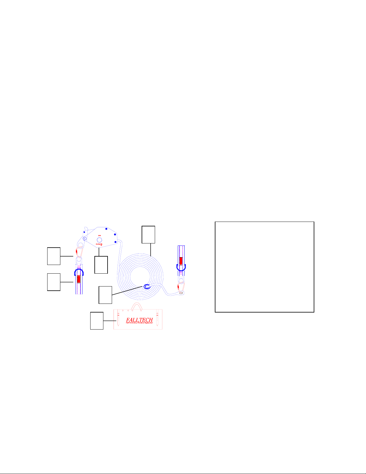
2
1
4
1. Anchor sling (2)
2. Self-locking carabiner
(2)
3. Horizontal line
3
tensioning device
4. Polyester rope lifeline
5. O-Rings (2)
5
6. Storage bag
6
FALLTECH
ALEXANDER ANDREW, INC.
10240 S Alameda St
South Gate, CA 90280-5551
Phone (800) 719-4619 Fax (323) 752-5613
3
Page 4

Instruction #I-77000, Rev 2
2.0 PRODUCT SPECIFICATIONS
Lifeline
Diameter 5/8”
Weight 13.1 lbs. per 100 ft
Material of Construction 12 Strand Polyester Fiber Rope
Average Breaking Strength 17,100 lbs.
Specific Gravity 1.38
Elongation 1.4% stretch at 10% of Break Strength
2.3% stretch at 20% of Break Strength
3% stretch at 30% of Break Strength
Chemical Resistance High resistance to acids
Line Tensioner
Material of Construction Steel with corrosion resistant finish
Minimum Breaking Strength 5,600 lbs.
Anchor Slings
Material of Construction:
Web Polyester
Small D-Ring Drop forged – alloy steel. Standard finish,
Yellow cadmium.
Large D-Ring Plating: Zinc to ASTM B-663, Zinc Spec. QQZ,
Class 2, 0.0005 + Silica Seal.
Webbing - Min. Tensile Strength 6,000 lbs.
D-Ring – Min. Tensile Strength 5,000 lbs.
Proof Loaded 100% up to 3,600 lbs.
Carabiners
Material of Construction Heat treated alloy steel. Finish is plated to BS1706-
FE-ZN5C.
Min. Breaking Load 11,000 lbs.
Proof Loaded 100% to 3,600 lbs.
O-Rings
Inside Diameter 3”
Outside Diameter 3-3/4”
Material of Construction Drop forged alloy steel.
Min. Tensile Strength 5,000 lbs.
Proof Loaded 100% up to 3,600 lbs.
FALLTECH
ALEXANDER ANDREW, INC.
10240 S Alameda St
South Gate, CA 90280-5551
Phone (800) 719-4619 Fax (323) 752-5613
4
Page 5

Instruction #I-77000, Rev 2
3.0 SYSTEM REQUIREMENTS
Personal Fall Arrest System Components
The FallTech™ horizontal lifeline system has been designed to be used with approved
FallTech™ components and sub-systems only. Non-approved components and subsystems may be incompatible and could affect the overall system. These components
must meet all applicable OSHA and ANSI standards. A full body harness like those
manufactured by FallTech™ must be used with this system.
System Components
Connectors (snap hooks, carabiners, D-rings) used to attach to the system O-ring(s) must
support a minimum of 5,000 lbs. Only use connectors that are compatible in shape, size,
and strength. Failure to do so may cause accidental roll-out. DO NOT use non-locking
connectors.
Structural Anchor Points
Anchor points must be stiff and capable of supporting a minimum of 5,000 lbs. Anchor
points must also be able to support 5,000 lbs in all directions of a potential fall.
Anchorage Connectors
Connectors must be capable of holding 5,000 lbs without breaking. Connectors must be
compatible with the connection point.
Sub-System Connections
A sub-system connection is the component used to attach the users harness to the
horizontal lifeline. Sub-system connections typically are self-retracting lifelines and
lanyards
Limitations Of System
System Capacity – The FallTech™ 77000 Temporary Horizontal Lifeline System has a
maximum capacity of two workers. There must also be adequate clearance beneath the
walking/working surface (see section titled “Clearance” below) for the system to function
properly. The maximum worker’s weight, including tools, cannot exceed 310 pounds
each. Consult your FallTech™ sales representative if you have any questions concerning
your application.
Corrosion – Harsh environments can cause corrosion of metal parts. The Temporary
Horizontal Lifeline System should not be left in corrosive environments for extended
periods of time. Additional inspections may be necessary to verify that the lifeline and
components are in good working condition.
Electrical Hazards – User should always use extreme caution when working near
electrical sources.
FALLTECH
ALEXANDER ANDREW, INC.
10240 S Alameda St
South Gate, CA 90280-5551
Phone (800) 719-4619 Fax (323) 752-5613
5
Page 6

Instruction #I-77000, Rev 2
Heat – Do not use this device in extremely high temperatures. When performing any
type of metal work, such as welding, cover fall arrest equipment.
Moving Machinery – If it is necessary to work above moving machinery, maintain a safe
distance between the moving parts and yourself, clothing, and personal protective
equipment.
Sharp Edges – Fall arrest equipment should always be protected from sharp edges. Sharp
or abrasive edges can cause excessive wear to equipment. If it is necessary to work
around these types of surfaces, always use a wear pad or barrier.
Clearance – There must be sufficient clearance beneath the structure to ensure that
workers do not contact an obstruction below. The following factors MUST be
considered when working with a horizontal lifeline system:
• Vertical displacement of horizontal
• Maximum free fall distance - 6 feet
lifeline
• Displacement of harness D-ring - 1 foot • Deployment of shock absorber - 3.5 feet
• Safety margin – 2 feet • Horizontal lifeline is mounted above the
workers head
Contact your FallTech™ representative for additional information.
Swing Falls – It is important to work as close as possible under the horizontal lifeline to
minimize swing fall hazards. A swing fall hazard is a result of a worker walking and/or
working too far away from the horizontal lifeline. In the event of a fall, a worker that is
not close to the horizontal lifeline will swing in a pendulum like motion and could hit an
obstruction, causing a serious injury. To minimize this type of hazard, work as closely as
possible to the horizontal lifeline and carefully evaluate any obstructions below the
working surface.
4.0 IMPORTANT DO’S AND DON’TS
NOTE: The components, materials and anchorage of a personal fall arrest system must
be selected by a Competent Person to match the system’s application, and workplace
hazards and environment.
FALLTECH
ALEXANDER ANDREW, INC.
10240 S Alameda St
South Gate, CA 90280-5551
Phone (800) 719-4619 Fax (323) 752-5613
6
Page 7

Instruction #I-77000, Rev 2
DO DON’T
Use this device only with compatible
Repair or modify this device.
components from FallTech.
Inspect equipment before each use. Ignore warnings issued by Fall Protection
Manufacture.
Store equipment in a safe, dry area. Modify or repair Fall Arrest equipment.
Contact manufacture for instructions.
Keep all literature and instructions in a safe
place for easy, quick reference.
Use this equipment unless you have been
fully trained by a competent person and
fully understand how to use this equipment.
Keep all inspection documents updated. Use this device if it has been exposed to
corrosion, chemicals, excessive heat,
flames, electrical charge, or shows signs of
any physical damage or deformation.
Keep all labels on fall protection
equipment readable.
Use this device if your total combined
weight (body, clothing, tools, etc.) exceeds
310 lb.
Use extreme caution when rigging this
equipment.
Plan for a rescue if a worker becomes
unconscious or incapacitated and falls.
Use anchorage points unless they have
been designed for fall protection.
Rely on the sound of a closing snap hook.
Visually inspect it to ensure a proper
attachment.
Call FallTech™ at (800) 719-4619 if the
device is damaged or does not function
according to the correct operation
explained in section 3 of this manual.
Use this system if you are pregnant, a
minor, or have reduced tolerance to fall
forces by reason of age, physical or
medical condition, or other pre-existing
disorders.
DO NOT USE THIS DEVICE IF IT HAS BEEN USED AS PART OF A SYSTEM
THAT HAS ARRESTED A FALL. IF IT HAS BEEN USED IN SUCH A SYSTEM, IT
MUST BE REMOVED FROM SERVICE IMMEDIATELY AND SENT TO
FALLTECH FOR INSPECTION AND SERVICING.
5.0 FALL PROTECTION PLAN
As an employer, you must be aware of the factors which affect the safety of your workers
before, during and after a fall. Having a Fall Protection Plan ready before work is the
best way to ensure the ultimate safety and well-being of your employees.
Your Fall Protection Plan must include:
FALLTECH
ALEXANDER ANDREW, INC.
10240 S Alameda St
South Gate, CA 90280-5551
Phone (800) 719-4619 Fax (323) 752-5613
7
Page 8

Instruction #I-77000, Rev 2
1. Proper Anchorage: A Properly selected anchorage point is critical to the success of a
personal fall arrest system (PFAS). The anchorage point must be rigid and allow for
a 2:1 safety factor.
2. Free Fall Limitations: Free fall distance must be taken into consideration when
designing a fall protection system. Potential free falls may not exceed 6 ft. To
reduce free fall distance, keep anchorage points above your working level.
Note: ANSI A10.14 requires personal fall arrest systems to be rigged so that the
potential free fall is not greater than 5 ft.
3. Fall Clearance Distance: Measure the distance between the working level and the
next obstruction. Then, design a system that will not allow a worker to come in
contact with the obstruction or next level.
4. Swing Falls: If a worker is not directly under an anchorage point, a swing fall may
result. To minimize this hazard, evaluate the entire situation, and plan accordingly
for a safe clearance distance, or consider a horizontal lifeline. Contact FallTech for
assistance.
5. Rescue and evacuation plan. You must provide a means of rescue and evacuation for
workers should a fall occur.
6. Immediately dispose of equipment which has been subjected to fall arrest forces.
6.0 OPERATION AND INSTALLATION OF FALLTECH TEMPORARY
HORIZONTAL LIFELINE SYSTEM
One complete temporary horizontal lifeline system includes the following components:
Part
Description Qty
Number
7372 Anchor Slings 2
7450 Self-locking carabiners 2
7349 Horizontal lifeline tensioning device 1
Varies Rope Lifeline 30’, 60’, 100’
7401 O-Rings 2
5007L Equipment Bag 1
INSTALLATION OF LIFELINE TO SUPPORT STRUCTURE USING ANCHOR
SLINGS
NOTE: Although anchor slings are included with system, self-locking carabiners may be
attached directly to an approved anchor point.
1. Wrap polyester anchor sling around one support structure. Sling must be wrapped
around column at least twice and fit up snugly against structure.
2. Take one self-locking carabiner and attach to smaller D-ring on anchor sling.
3. Wrap second anchor sling around opposite support structure. Repeat steps #1 and #2.
FALLTECH
ALEXANDER ANDREW, INC.
10240 S Alameda St
South Gate, CA 90280-5551
Phone (800) 719-4619 Fax (323) 752-5613
8
Page 9

Instruction #I-77000, Rev 2
4. Connect thimbled end of lifeline to one of the anchor slings using a self-locking
carabiner.
5. Tighten horizontal lifeline by pulling loose rope end at lifeline tensioner. Using a
solid piece of steel stock, tighten the lifeline by turning the nut clockwise. Proper
tension will be achieved when inner cam wheel turns and HLL rope remains
stationary. Do not over tension lifeline.
6. Once horizontal lifeline has been tensioned properly, push unfastening lever against
tensioner. See Figure #1.
FIGURE #1
7. Take excess horizontal lifeline and tie in knot close to tensioner.
8. Use only FallTech™ approved shock absorbing lanyards or self-retracting lifelines
for attachment to horizontal lifeline. Shock absorbing lanyards cannot be directly
attached to horizontal lifeline; they must be attached to the O-rings included with
system. Each O-Ring is rated for one shock absorbing lanyard or self-retracting
lifeline attachment.
DISMANTELING HORIZONTAL LIFELINE SYSTEM
With a screw driver or connecting type bar, raise unfastening lever. Loosen lifeline by
sliding through tensioner. Disconnect self locking carabiner from anchor sling D-Ring or
anchorage point. Loosen anchor slings and remove from support structure.
IMPORTANT: If you fall, remove the horizontal lifeline system from service and
immediately report incident to your supervisor or the safety department.
7.0 MAINTENANCE & STORAGE
1. Inspection must be carried out by a competent person trained in the inspection and
replacement of the system. A record log of all servicing and inspection dates for this
system should be maintained by the company safety officers at intervals of no less
FALLTECH
ALEXANDER ANDREW, INC.
10240 S Alameda St
South Gate, CA 90280-5551
Phone (800) 719-4619 Fax (323) 752-5613
9
Page 10

Instruction #I-77000, Rev 2
than twice per year. This system and all components must be withdrawn from service
if subjected to fall arresting forces. Only original FallTech™ Replacement parts are
approved for use in this device. Contact your FallTech™ distributor or FallTech™
Customer Service Department at (800) 719-4619 if you have any questions.
2. Maintenance and storage of equipment shall be conducted by the user’s organization
in accordance with FallTech™ instructions. Unique issues which may arise due to
conditions of use shall be addressed with FallTech™.
3. Equipment which is in need of or scheduled for maintenance shall be tagged “DO
NOT USE” and removed from service.
4. Hardware should be wiped clean with a rag to remove dirt and grease. Lubricate with
a light oil to insure good working order and protect against corrosion. Wipe off
excessive amounts of oil to avoid the accumulation of dirt.
5. Store in a clean, dry area free from excessive heat, steam, sunlight, harmful fumes,
corrosive agents and rodents.
WARNING: DO NOT USE FALL PROTECTION EQUIPMENT THAT HAS NOT
BEEN MAINTAINED AND STORED PROPERLY.
8.0 INSPECTION
Inspection procedures for in field visual inspection:
1. The FallTech™ Systems shall be inspected by the user before each use and
additionally by a Competent Person other than the user at intervals of no less than
twice a year. If equipment is in a very harsh and/or corrosive environment, additional
inspections may be necessary. Detailed inspections must be recorded. A
comprehensive Inspection Checklist is included with all FallTech™ instructions.
2. If an inspection reveals defects that could affect the function of the Personal
Protective Equipment, remove from service immediately and discard or all Protection
equipment, damage, or inadequate maintenance of the system, the components
affected shall be permanently removed from service to undergo adequate corrective
maintenance before return to service.
3. Remove the system from service if:
• The system has arrested a fall;
• The system has not been inspected in the last six months;
• The label(s) is missing or illegible;
• Alteration of any components;
• Inspection reveals excessive wear, cracks, or signs of deformation.
Only FallTech™ manufacturing personnel or entities authorized in writing by the
manufacturer shall make repairs to the equipment. No unauthorized repairs or
modifications are allowed.
FALLTECH
ALEXANDER ANDREW, INC.
10240 S Alameda St
South Gate, CA 90280-5551
Phone (800) 719-4619 Fax (323) 752-5613
10
Page 11

Instruction #I-77000, Rev 2
Inspection Guidelines:
Every time the horizontal lifeline is used, inspect it for excessive wear or damage. If
there are any defective conditions, remove immediately from service immediately.
Inspect all termination hardware and cables for cuts, abrasions or excessive wear.
Excessive wear is a signal to retire cable from service and replace with new cable and
hardware. NOTE: Remove the sources of damage away from the system.
Check clearance below the walking/working surface including obstructions in the path of
a potential fall. If there are any sharp or dangerous obstructions below walking/working
surface, remove from the path of a possible fall.
Maintenance:
1. Inspect all hardware for distortion and deformation. Check for visible cracks,
excessive wear and tear, corrosion and chemical erosion. Also, remove hardware if
there are sharp edges.
2. Inspect anchor points for physical damage, wear or corrosion that could affect their
function in the event of a fall.
3. Inspect carabiners and snaphooks to ensure that gate operates properly.
4. Inspect all hardware for correct operation, broken or missing pieces, and loose or
missing items.
5. Inspect all synthetic lifelines for cuts, fraying, fluffing, abrasion, melting and
chemical wear.
6. Inspect synthetic harnesses and lanyards for the same items outlined in #5, in addition
to inspecting for discoloration, damaged stitching, and exposed warning labels.
7. Inspect all labels to ensure that the Personal Fall Protection equipment has been
inspected by a Competent Person. Labels must be readable at all times.
FALLTECH
ALEXANDER ANDREW, INC.
10240 S Alameda St
South Gate, CA 90280-5551
Phone (800) 719-4619 Fax (323) 752-5613
11
Page 12

Instruction #I-77000, Rev 2
INSPECTION LOG INSPECTION LOG
Manufacturer: Manufacturer:
Model No: Model No:
Mfg. Date: Mfg. Date:
INSPECTION LOG INSPECTION LOG
Manufacturer: Manufacturer:
Model No: Model No:
Mfg. Date: Mfg. Date:
INSPECTION LOG INSPECTION LOG
Manufacturer: Manufacturer:
Model No: Model No:
Mfg. Date: Mfg. Date:
Part Inspection
Date
Inspector Comments Pass/Fail Corrective
Action
Approved
By
Taken
Anchor
Sling
Self-locking
carabiner
Tensioner
Lifeline
O-Rings
WARRANTY
FallTech warrants to the purchaser that the product is free from defects in material and
workmanship, and agrees to replace any defective product within one (1) year from date
of installation or use by the owner, provided that this period shall not exceed two (2)
years from the date of shipment. This warranty is non-transferable. Warranty covers
defects in material or workmanship; it does not cover conditions resulting from normal
wear and tear, neglect, abuse or accident. All returns must have return authorization,
obtained from Customer Service, and all shipments of returned goods must be prepaid.
FALLTECH
ALEXANDER ANDREW, INC.
10240 S Alameda St
South Gate, CA 90280-5551
Phone (800) 719-4619 Fax (323) 752-5613
12
 Loading...