

Falcon G2962, G2965, G2995, G2994 Installation And Servicing Instructions

G2962, G2994
T100723 Ref. 3
Manual-tilt Bratt Pans
G2965 and G2995
Auto-tilt Bratt Pans
INSTALLATION and SERVICING
INSTRUCTIONS
These appliances must be installed and serviced by a qualified person as stipulated by the Gas Safety (Installation &
Use) Regulations.
IMPORTANT
The installer must ensure that the installation of the appliance is in conformity with these instructions and National Regulations
in force at the time of installation. Particular attention MUST be paid to -
I.E.E Regulations for Electrical Installations
Electricity At Work Regulations
Gas Safety (Installation & Use) Regulations
Health And Safety At Work etc. Act
Local and National Building Regulations
These appliances have been CE-marked on the basis of compliance with the Gas Appliance Directive, EMC and Low Voltage
Directive for the Countries, Gas Types and Pressures as stated on the data plate.
WARNING - TO PREVENT SHOCKS, ALL APPLIANCES WHETHER GAS OR ELECTRIC MUST BE EARTHED.
On completion of the installation, these instructions should be left with the Engineer-in-Charge for reference during servicing.
Further to this, The Users Instructions should be handed over to the User, having had a demonstration of the operation and
cleaning of the appliance.
IT IS MOST IMPORTANT THAT THESE INSTRUCTIONS BE CONSULTED BEFORE INSTALLING AND COMMISSIONING
THIS APPLIANCE. FAILURE TO COMPLY WITH THE SPECIFIED PROCEDURES MAY RESULT IN DAMAGE OR THE
NEED FOR A SERVICE CALL.
PREVENTATIVE MAINTENANCE CONTRACT
In order to obtain maximum performance from this appliance we would recommend that a maintenance contract be arranged
with SERVICELINE. Visits may then be made at agreed intervals to carry out adjustments and repairs. A quotation for this
service will be given upon request to the contact numbers below.
WEEE Directive Registration No. WEE/DC0059TT/PRO
At end of appliance life, dispose of appliance and any replacement parts
in a safe manner, via a licensed waste handler.
Appliances are designed to be dismantled easily and recycling of all
material is encouraged whenever practicable.
Fire Precautions Act
Detailed recommendations are contained in Institute of
Gas Engineers published documents:
IGE/ UP/ 1, IGE/ UP/ 2
BS6173 and BS5440
Falcon Foodservice Equipment
HEAD OFFICE AND WORKS
Wallace View, Hillfoots Road, Stirling. FK9 5PY. Scotland.
SERVICELINE CONTACT
Phone: 01438 363 000 Fax: 01438 369 900

Warranty Policy Shortlist
Warranty does not cover :Correcting faults caused by incorrect installation of a product.
Where an engineer cannot gain access to a site or a product.
Repeat commission visits.
Replacement of any parts where damage has been caused by misuse.
Engineer waiting time will be chargeable.
Routine maintenance and cleaning.
Gas conversions i.e. Natural to Propane gas.
Descaling of water products and cleaning of water sensors where softeners/conditioners are not fitted, or are fitted
and not maintained.
Blocked drains.
Independent steam generation systems.
Gas, water and electrical supply external to appliance.
Light bulbs.
Re-installing vacuum in kettle jackets.
Replacement of grill burner ceramics when damage has been clearly caused by misuse.
Where an engineer finds no fault with a product that has been reported faulty.
Re-setting or adjustment of thermostats when appliance is operating to specification.
Cleaning and unblocking of fryer filter systems due to customer misuse.
Lubrication and adjustment of door catches.
Cleaning and Maintenance
• Cleaning of burner jets
• Poor combustion caused by lack of cleaning
• Lubrication of moving parts
• Lubrication of gas cocks
• Cleaning/adjustment of pilots
• Correction of gas pressure to appliance.
• Renewing of electric cable ends.
• Replacement of fuses
• Corrosion caused by use of chemical cleaners.

SECTION 1 – INSTALLATION
MODEL
WIDTH
mm
DEPTH
mm
HEIGHT
mm
WEIGHT
kg
WEIGHT
lbs
G2962
600
770
870
120
265
G2965
600
770
870
120
265
G2994
900
770
870
165
364
G2995
900
770
870
165
364
UNLESS OTHERWISE STATED, PARTS WHICH HAVE BEEN PROTECTED BY THE MANUFACTURER ARE
NOT TO BE ADJUSTED BY THE INSTALLER.
1.1 MODEL NUMBERS, NETT WEIGHTS and
DIMENSIONS
1.2 SITING
The appliance should be installed on a level, fireproof
surface, in a well lit and draught free position within a
suitably ventilated room. If floor is constructed of
combustible material then local fire requirements
should be checked to ensure compliance. A clear
space of 150mm should be left between appliance
rear and any combustible wall. A minimum vertical
clearance of 900mm above top edge of appliance is
required.
Important
If appliance is to be installed in a suite formation with
matching appliances then instructions for all models
should be consulted in order to determine necessary
clearances to any combustible rear wall or overlying
surface(s). Some appliances require greater
clearances than others. The largest figure quoted in
the individual instructions will therefore determine
clearance of the complete suite adjoining appliances.
Flue discharges vertically along top rear of appliance.
THERE MUST BE NO DIRECT CONNECTION OF
THE FLUE TO THE OUTSIDE AIR OR TO A
MECHANICAL EXTRACTION SYSTEM.
See Section 1.3 for ventilation details.
After appliance position has been established, it is
recommended that the feet (on an appliance fitted
with feet) be secured to floor using holes provided.
1.3 VENTILATION
This appliance must be installed in a suitably
ventilated room in accordance with the regulations in
force.
Sufficient ventilation, natural or mechanical, must be
provided to supply adequate fresh air for proper
combustion.
It should also prevent occurrence of unacceptable
concentrations of substances harmful to health in the
location where equipment is installed. It is also
required to be able to remove any such products that
may occur, safely and efficiently.
Recommendations for Ventilation of Catering
Appliances are provided in BS5440: 2. For multiple
installations, requirements for individual appliances
should be added together. Installation should be
made in accordance with local and/or national
regulations which apply at the time.
A qualified installer MUST be employed.
1.4 GAS SUPPLY
The incoming service must be of sufficient size to
supply full rate without excessive pressure drop. The
gas meter should be checked, preferably by the gas
supplier to ensure meter is adequate to deal with rate
of gas supply required for the appliance in addition to
any other gas equipment installed.
Installation pipes should be fitted in accordance with
IGE/UP/2. The size of pipework from meter to
appliance must not be less than appliance inlet
connection Rp1/2• (1/2" BSP female). An isolating
cock that is easily accessible to user must be located
close to appliance to allow shut down during any
emergency or routine servicing. The installation must
be tested for gas tightness. Details are given in
IGE/UP/1.
Position of isolating cock should be shown to
responsible person(s).
The gas supply tubing or hose must comply with
national requirements in force and require to be
periodically examined and replaced as necessary.
Flexible hose length must not exceed 1.5M.
1.5 ELECTRICAL SUPPLY
Model
kW (nett)
Btu/hr (gross)
G2962/2965
9.8
36,800
G2994/2995
15.9
59,700
NATURAL
PROPANE
20 mbar
8 in. w.g.
37 mbar
14.8 in. w.g.
Model
NATURAL
PROPANE
G2962/2965
15 mbar
6 in. w.g.
35.5 mbar
14.2 in. w.g.
G2994/2995
35 mbar
14 in. w.g.
G2962/2965
NATURAL
PROPANE
MAIN BURNER
RH
Amal 470
Amal 180
MAIN BURNER
LH
Amal 400
Amal 180
PILOT
BURNER
SIT No. 36
SIT No. 19
CROSS-LIGHTING
BURNER
Amal 75
Amal 20
MAIN BURNER
RH
Amal 490
Amal 190
MAIN BURNER
CENTRE
Amal 400
Amal 190
MAIN BURNER
LH
Amal 430
Amal 190
PILOT
BURNER
SIT No. 36
SIT No. 19
CROSS-LIGHTING
BURNER - LH
Amal 75
Amal 20
CROSS-LIGHTING
BURNER - RH
Amal 85
Amal 20
G2994/2995
NATURAL
PROPANE
1.9 GAS PRESSURE
These appliances are designed for operation on a
230V~ 50Hz 3A electrical supply.
As mains lead wire colours may not correspond with
the markings which identify plug terminals, proceed
as follows:
The wire coloured GREEN and YELLOW must be
connected to plug terminal which is marked with the
letter E or the earth symbol or coloured GREEN or
GREEN and YELLOW.
The wire coloured BLUE must be connected to
terminal marked with letter N or coloured BLACK.
The wire coloured BROWN must be connected to
terminal marked with letter L or coloured RED.
1.6 WATER SUPPLY
Not applicable to these appliances.
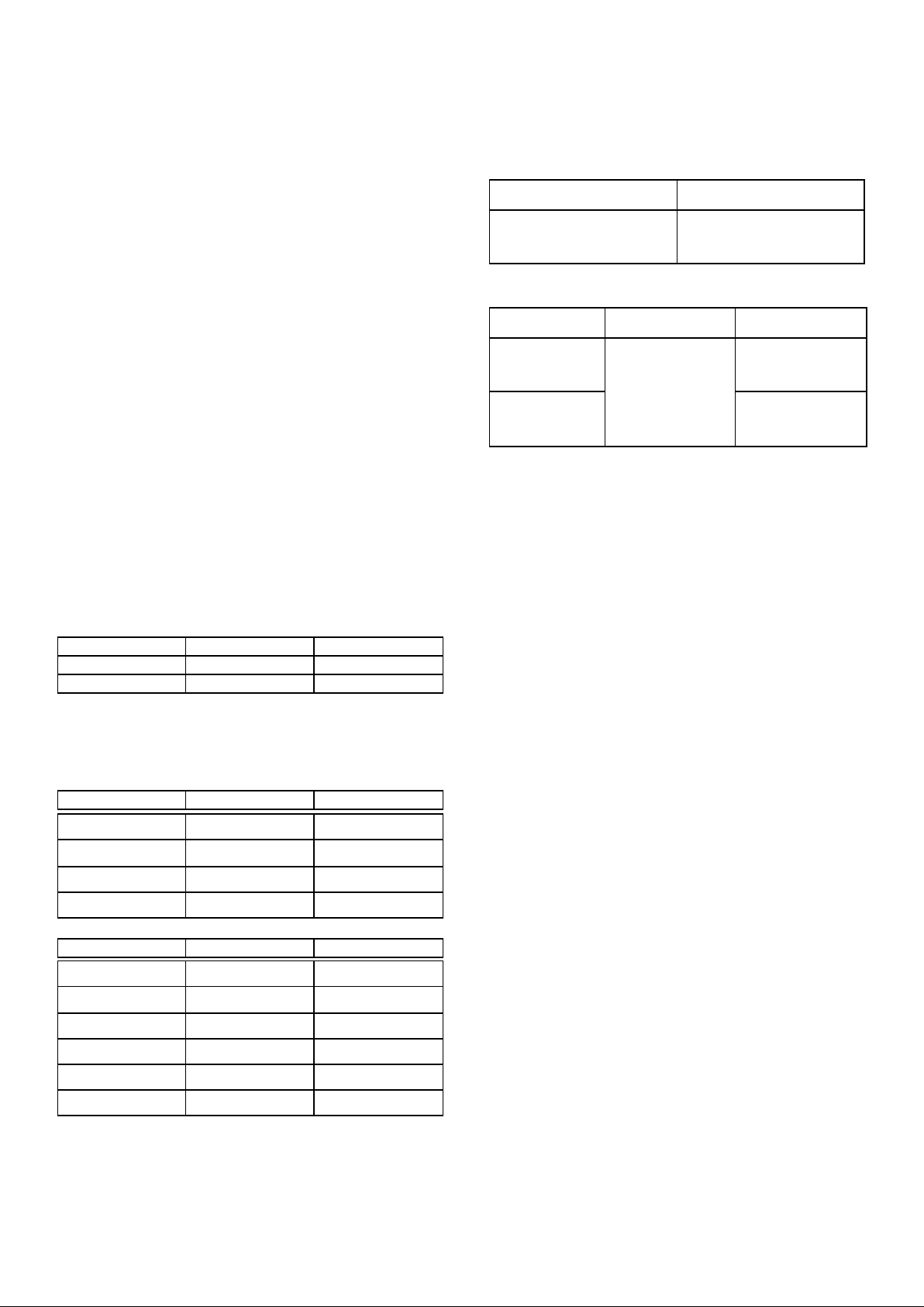
1.7 TOTAL RATED HEAT INPUTS –
NATURAL (I2H) and PROPANE (I3P) GAS
The appliance operates at the following pressures -
Supply Pressure (All Models)
Operating Pressure
Operating pressure is measured at outlet test point
located on front face of multi-functional control – (See
Figure 1, Servicing Section 3.8)
1.10 BURNER ADJUSTMENT
The only adjustment necessary on main burner is the
correct setting of gas pressures as described in
Section 1.9.
1.8 INJECTOR SIZES NATURAL (I2H) and PROPANE (I3P) GAS
No aeration adjustment is provided.
Pilot flame should envelop approximately 6mm to
10mm of thermocouple tip. Pilot flame can be
adjusted using the Pilot Adjustment screw on front of
Multi-functional Control Valve (turn screw clockwise
to reduce and anti-clockwise to increase) – (see
Figure 1, Servicing Section 3.8).
If any adjustment is required, appliance must be
serviced.

SECTION 2 - ASSEMBLY and
COMMISSIONING
2.1 ASSEMBLY
Position appliance and level by adjusting leg levelling
feet or castors as appropriate. Each foot (on
appliances with feet) contains a hole to enable floor
fixing to be made.
2.1.1 Appliance s on Castors
Refer to addendum T100286 supplied.
In addition, drain contents of pan before attempting to
move appliance, pan must also be lowered down fully
prior to moving.
2.2 CONNECTION TO THE GAS SUPPLY
Inlet connection terminates at bottom RH corner
when vi ewed from rear and is Rp1/2 (1/2" BSP
Female). Test for gas tightness.
2.3 CONNECTION TO ELECTRICITY SUPPLY
Make electrical connection.
Appliance is designed for connection to a 230V AC
supply. A 2 metre long mains lead is fitted as
standard. Mains lead wires are coloured in
accordance with the following code:
2.5 PRE-COMMISSIONING CHECK
Important
After installation, the engineer should check that all
gas connections are tight and do not leak. Also check
that all electrical connections are secure.
The installation engineer should check that the
appliance is operating satisfactorily before leaving
site.
Particular attention should be given to pressure
settings detailed in Section 1.9 and pilot adjustment
as detailed in Section 1.10.
2.6 INSTRUCTION TO USER
After installing and commissioning appliance, please
hand User Instructions to user or purchaser and
ensure that person(s) responsible understand the
instructions and procedures for lighting, cleaning and
correct use of appliance.
It is important to ensure that locations of gas isolating
cock and electrical socket or switch are made known
to user and procedures for operating these in an
emergency are demonstrated.
Green and Yellow Earth
Blue Neutral
Brown Live
The wires should be connected to plug as follows:
EARTH to terminal marked E, or coloured GREEN.
NEUTRAL to terminal marked N or coloured BLACK.
LIVE to terminal marked L, or coloured RED.
Appliance must be protected by 3 amp fuse if 13 amp
(BS1363) plug is used. Any other type of connection
must be protected by 5 amp fuse at distribution
board.
Warning
THIS APPLIANCE MUST BE EARTHED.
2.4 CONNECTION TO THE WATER SUPPLY
Not applicable to this appliance.
 Loading...