

Falcon G2625, G21225, G2925, G21525, G21825 User Instructions
...
T100565 Ref. 7
G2625, G2925, G21225
G21525 and G21825 CHARGRILLS
G2625B, G2925B, G21225B
G21525B and G21825B CHARGRILLS
USERS INSTRUCTIONS
SECTION 1 - GENERAL DESCRIPTION
SECTION 2 - LIGHTING and OPERATIONS
SECTION 3 - COOKING HINTS
SECTION 4 - CLEANING and MAINTENANCE
These appliances have been CE-marked on the basis of compliance with the Gas Appliance Directive, for the
Countries, Gas Types and Pressures as stated on the Data Plate.
These appliances MUST BE installed by a qualified person in compliance with the INSTALLATION AND
SERVICING INSTRUCTIONS and National Regulations in force at the time. Particular attention MUST be paid
to the following:
Gas Safety (Installation & Use) Regulations
Health and Safety at Work Act
Furthermore, if a need arises to convert the appliance for use with another gas, a qualified person must be
consulted. Those parts which have been protected by the manufacturer MUST NOT be adjusted by the User.
Users should be conversant with the appropriate provisions of the Fire Precautions Act and the requirements of
the Gas Safety Regulations. In particular, the need for regular servicing by a competent person to ensure the
continued safe and efficient performance of the Appliance.
WARNING - TO PREVENT SHOCKS, ALL APPLIANCES WHETHER
GAS OR ELECTRIC, MUST BE EARTHED
Upon receipt of the User's Instruction manual, the installer should instruct the responsible person(s) of the
correct operation and maintenance of the Appliance.
This equipment is ONLY FOR PROFESSIONAL USE, and shall be operated by QUALIFIED persons. It is the
responsibility of the Supervisor or equivalent to ensure that users wear SUITABLE PROTECTIVE CLOTHING
and to draw attention to the fact that, some parts will, by necessity, become VERY HOT and will cause burns if
touched accidentally.
WEEE Directive Registration No. WEE/DC0059TT/PRO
At end of unit life, dispose of appliance and any replacement parts
in a safe manner, via a licenced waste handler.
Units are designed to be dismantled easily and recycling of all
material is encouraged whenever practicable.
Falcon Foodservice Equipment
HEAD OFFICE AND WORKS
Wallace View, Hillfoots Road, Stirling FK9 5PY
SERVICELINE CONTACT -
PHONE - 01438 363 000 FAX - 01438 369 900
Locate radiants
over lugs
OFF
PILOT
HIGH LOW
SECTION 1 - GENERAL DESCRIPTION
The chargrills, part of the Dominator Series, are
supplied on a stand. They can also be installed upon
a counter or table using a bench mounting kit
supplied by Falcon.
G2625, G2925, G21225, G21525 and G21825
chargrills are controlled by a combined on/off tap
and flame failure device. Standard burner ignition is
by pilot, lit manually using a hand held gas lighter.
G2625B, G2925B, G21225B, G21525B and
G21825B chargrills are controlled by a combined
on/off tap and flame failure device. Standard burner
ignition is by pilot, lit by piezo ignition. Back-up
ignition is by gas lighter.
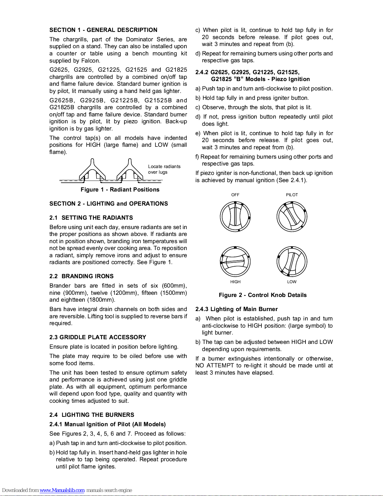
The control tap(s) on all models have indented
positions for HIGH (large flame) and LOW (small
flame).
Figure 1 - Radiant Positions
SECTION 2 - LIGHTING and OPERATIONS
2.1 SETTING THE RADIANTS
Before using unit each day, ensure radiants are set in
the proper positions as shown above. If radiants are
not in position shown, branding iron temperatures will
not be spread evenly over cooking area. To reposition
a radiant, simply remove irons and adjust to ensure
radiants are positioned correctly. See Figure 1.
2.2 BRANDING IRONS
Brander bars are fitted in sets of six (600m m),
nine (900mm), twelve (1200mm), fifteen (1500mm)
and eightteen (1800mm).
Bars have integral drain channels on both sides and
are reversible. Lifting tool is supplied to reverse bars if
required.
2.3 GRIDDLE PLATE ACCESSORY
Ensure plate is located in position before lighting.
The plate may require to be oiled before use with
some food items.
The unit has been tested to ensure optimum safety
and performance is achieved using just one griddle
plate. As with all equipment, optimum performance
will depend upon food type, quality and quantity with
cooking times adjusted to suit.
2.4 LIGHTING THE BURNERS
2.4.1 Manual Ignition of Pilot (All Models)
See Figures 2, 3, 4, 5, 6 and 7. Proceed as follows:
a) Push tap in and turn anti-clockwise to pilot position.
b) Hold tap fully in. Insert hand-held gas lighter in hole
relative to tap being operated. Repeat procedure
until pilot flame ignites.
c) When pilot is lit, continue to hold tap fully in for
20 seconds before release. If pilot goes out,
wait 3 minutes and repeat from (b).
d) Repeat for remaining burners using other ports and
respective gas taps.
2.4.2 G2625, G2925, G21225, G21525,
G21825 "B" Models - Piezo Ignition
a) Push tap in and turn anti-clockwise to pilot position.
b) Hold tap fully in and press igniter button.
c) Observe, through the slots, that pilot is lit.
d) If not, press ignition button repeatedly until pilot
does light.
e) When pilot is lit, continue to hold tap fully in for
20 seconds before release. If pilot goes out,
wait 3 minutes and repeat from (b).
f) Repeat for remaining burners using other ports and
respective gas taps.
If piezo igniter is non-functional, then back up ignition
is achieved by manual ignition (See 2.4.1).
Figure 2 - Control Knob Details
2.4.3 Lighting of Main Burner
a) When pilot is established, push tap in and turn
anti-clockwise to HIGH position: (large symbol) to
light burner.
b) The tap can be adjusted between HIGH and LOW
depending upon requirements.
If a burner extinguishes intentionally or otherwise,
NO ATTEMPT to re-light it should be made until at
least 3 minutes have elapsed.
 Loading...