

Falcon G2102 C, G2112 C/2, G2112 C Installation And Servicing Instructions
G2102 C CONVECTION OVEN RANGE
G2112 C & G2112 C/2 CONVECTION
OVENS
INSTALLATION and SERVICING INSTRUCTIONS
These appliances must be installed and serviced by a competent person as stipulated by the Gas
Safety (Installation & Use) Regulations.
IMPORTANT
The installer must ensure that the installation of the appliance is in conformity with these instructions and
National Regulations in force at the time of installation. Particular attention MUST be paid to –
BS7671 I.E.E. Wiring Regulations
Electricity At Work Regulations
Gas Safety (Installation & Use) Regulations
Health And Safety At Work etc. Act
Local and National Building Regulations
Fire Precautions Act
Detailed recommendations are contained in
Institute
Of Gas Engineers published documents:
IGE/ UP/ 1, IGE/ UP/ 2
BS6173 and BS5440
The appliances have been CE-marked on the basis of compliance with the Gas Appliance Directive, EMC
and Low Voltage Directive for the Countries, Gas Types, Gas Pressures and voltages as stated on the
Data Plate.
WARNING - TO PREVENT SHOCKS, ALL APPLIANCES MUST BE EARTHED
On completion of the installation, these instructions should be left with the Engineer-in-Charge for reference
during servicing. Further to this, The Users Instructions should be handed over to the User, having had a
demonstration of the operation and cleaning of the appliance.
IT IS MOST IMPORTANT THAT THESE INSTRUCTIONS BE CONSULTED BEFORE INSTALLING AND
COMMISSIONING THIS APPLIANCE. FAILURE TO COMPLY WITH THE SPECIFIED PROCEDURES
MAY RESULT IN DAMAGE OR THE NEED FOR A SERVICE CALL.
PREVENTATIVE MAINTENANCE CONTRACT
In order to obtain maximum performance from this unit we would recommend that a Maintenance Contract
be arranged with SERVICELINE. Visits may then be made at agreed intervals to carry out adjustments and
repairs. A quotation will be given upon request to the contact numbers below.
WEEE Directive Registration No. WEE/DC0059TT/PRO
At end of unit life, dispose of appliance and any replacement parts in a safe manner,
via a licensed waste handler.
Units are designed to be dismantled easily and recycling of all material is encouraged
whenever practicable.
Falcon Foodservice Equipment
Head Office and Works
Wallace View, Hillfoots Road, Stirling, FK9 5PY, Scotland.
Serviceline
PHONE: 01438 363 000
T100970 Ref.2

Warranty Policy Shortlist
Warranty does not cover:Correcting faults caused by incorrect installation of a product.
Where an engineer cannot gain access to a site or a product.
Repeat commission visits.
Replacement of any parts where damage has been caused by misuse.
Engineer waiting time will be chargeable.
Routine maintenance and cleaning.
Gas conversions i.e. Natural to Propane gas.
Descaling of water products and cleaning of water sensors where softeners/conditioners are not fitted,
or are fitted and not maintained.
Blocked drains.
Independent steam generation systems.
Gas, water and electrical supply external to unit.
Light bulbs.
Re-installing vacuum in kettle jackets.
Replacement of grill burner ceramics when damage has been clearly caused by misuse.
Where an engineer finds no fault with a product that has been reported faulty.
Re-setting or adjustment of thermostats when unit is operating to specification.
Cleaning and unblocking of fryer filter systems due to customer misuse.
Lubrication and adjustment of door catches.
Cleaning and Maintenance
Cleaning of burner jets
Poor combustion caused by lack of cleaning
Lubrication of moving parts
Lubrication of gas cocks
Cleaning/adjustment of pilots
Correction of gas pressure to appliance.
Renewing of electric cable ends.
Replacement of fuses
Corrosion caused by use of chemical cleaners.

SECTION 1 – INSTALLATION
Important: Check that no damage has occurred to the appliance or power cable during
transit.
If damage has occurred do not install/use the appliance.
Installation, periodic testing, repair and fixed wiring connections should only be
undertaken by a competent electrician.
Ensure that the mains power cable is routed free from the appliance to avoid damage.
We recommend supplementary electrical protection with the use of a residual current
device.
Take care when removing or replacing cast iron components as they are heavy items.
Pan Support - 5kg
UNLESS OTHERWISE STATED, PARTS WHICH HAVE BEEN PROTECTED BY THE MANUFACTURER
ARE NOT TO BE ADJUSTED BY THE INSTALLER.
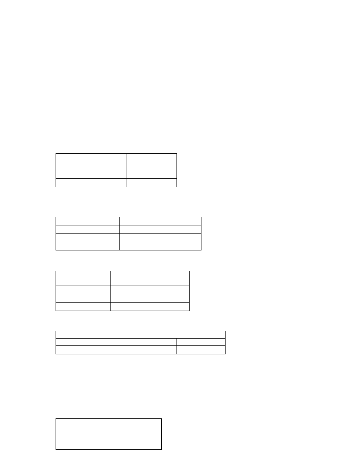
1.1 MODEL NUMBERS, NETT WEIGHTS and DIMENSIONS
MODEL
WIDTH
mm
DEPTH
mm
HEIGHT
mm
WEIGHT
kg
G2102 C
RANGE
900
770
870
221
G2112 C
OVEN ON STAND
900
770
1310
190
G2112 C/2
DOUBLE TIER OVEN
900
770
1465
362
1.2 SITING
All units, other than G2112 C oven on stand, must be installed on a non-combustible floor. All units
must be situated on a level surface. Although the appliance feet are adjustable to facilitate levelling,
the adjustment range is limited.
A clearance of at least 150mm must be allowed from any combustible wall.
If practicable, it is recommended that a space of at least 400mm be allowed from any side wall to
provide clearance for adjusting the rear levelling bolts, and to effect the removal of the RH side
panel to facilitate servicing.
A vertical clearance of 1200mm minimum must be allowed between the top edge of flue outlet and
any overlying combustible surface.
If unit is being installed as part of a suite, it is also recommended that it be positioned at the RH end
to provide unrestricted access for servicing the controls, etc. Furthermore, if installed in a suite,
either central or adjacent to a wall, with a boxed-in void at the rear, it is vitally important that the void
be adequately ventilated to ensure a supply of air to the motor cooling fan at the rear of the oven.
Important
Care must be taken not to disturb the air for combustion admission and evacuation of products of
combustion on appliances fitted with open burners.

1.3 VENTILATION
This appliance must be installed in a suitably ventilated room in accordance with the regulations in
force.
Adequate ventilation, whether natural or mechanical, must be provided to ensure sufficient fresh air
for combustion and for removal of combustion and cooking vapours.
The fresh air requirement for this appliance at a rate of 3M³/hour per kW is 150M³ of fresh air per
hour.
This appliance is to be installed with sufficient ventilation to prevent the occurrence of unacceptable
concentrations of substances harmful to health in the room which they are installed.
The appliance flue discharges vertically at the rear. There must be no direct connection of the flue
to outside air or to a mechanical extraction system. Standing the appliance below a ventilated
canopy is the most suitable arrangement.
Recommendations for ventilation for catering appliances are given in BS 5440:2.
For multiple installations, the requirements should be added together. Installation should be made in
accordance with local and/or national regulations applying at the time, and a competent installer
must be employed.
Care must be taken not to disturb the air for combustion admission and evacuation of products of
combustion on appliances fitted with open burners.
1.4 GAS SUPPLY
The incoming service must be of sufficient size to supply full rate without excessive pressure drop. A
gas meter is connected to the service pipe by the Gas Supplier. Any existing meter should be
checked by the Gas Supplier to ensure the meter is of adequate capacity to pass the required rate
of gas.
Installation pipe work should be fitted in accordance with IGE/UP/2. The pipe should be of adequate
size but not smaller than the gas inlet.
Gas supply tubing or hose shall comply with the national requirements in force, and shall be
periodically examined and replaced as necessary. The tubing or Flexible hose must not exceed
1.5m in length.
Connections are as follows:
G2102 C Range:
Rp3/4• (3/4" BSP female)
G2112 C Oven:
Rp1/2 (1/2"BSP female)
An isolating cock must be located close to the appliance to allow shut-down during an emergency or
servicing. The installation must be tested for gas soundness and purged as specified in IGE/UP/1.
The position of the isolating cock must be made known to the user of the equipment and/or
supervisor.
The isolating cock must be easily accessible to the users of the appliance.
Note
The G2102 C open top range is supplied complete with the necessary pipework for linking oven and
open top burner sections. The governor necessary for open top burners is incorporated in this
pipework for Natural Gas operation. The oven control valve incorporates a governor for the oven
and an extra governor must not be fitted to any of these appliances and an extra governor must not
be fitted to any of these appliances.
1.5 ELECTRICAL SUPPLY
Installation, periodic testing, repair and fixed wiring connections should only be
undertaken by a competent electrician.
The oven is equipped with a length of 3-core flexible cord for connecting to an electrical supply. A
standard 13 amp socket outlet can be used, in which case the plug must be fitted with a 3 amp fuse.
If the supply is through a distribution fuse box, it must be via a fuse having a maximum rating of 5
amps.
We recommend supplementary electrical protection with the use of a residual current device (RCD).
1.6 WATER SUPPLY
Not applicable to these appliances.
1.7 TOTAL GAS RATES -
Natural I2H and Propane Gas I3P
Model
kW (net)
Btu/hr (gross)
G2102 C
49.8
187,000
G2112 C
18
67,600
G2112 C/2
36
135,100
1.7.1 Individual Burner Ratings -
Natural I2H and Propane Gas I3P
Burner type
kW (net)
Btu/hr (gross)
Open Top (x6)
5.3
20,000
Oven
18
67,600
Oven Pilot/Ignition
0.25
940
1.8 INJECTOR DIAMETERS - Natural I2H & Propane Gas I3P
Natural
Gas I2H
Propane
Gas I3P
Open top
Ø1.92mm
Ø1.2mm
Oven
Ø3.3mm
Ø2.2mm
Oven Pilot
G29.2
G24.1
1.9 GAS PRESSURE
Supply Pressure
Burner Operating Pressure
Nat I2H
Prop I3P
Nat I2H
Prop I3P
mbar
20
37
15
37
1.10 BURNER ADJUSTMENTS
1.10.1 Burner Aeration
All burners have fixed aeration, and no modifications to the size of air-entry should be attempted.
1.10.2 Open Top Gas Tap – Low Position Screw Details
The Open Top Low Position flow to burner is governed by the size of the fixed hole in Low Position
Screw as detailed below: - The screw is located to Right hand side of the gas tap spindle.
Turndown Flow
1.1kW
Natural Gas I2H
No.76
Propane Gas I3P
No.51

1.11 FAN UNIT
This fan has two impellors, directly mounted on the motor shaft. The main impellor is inside the
oven, its purpose being to circulate air across the heat-exchangers and around the cooking space,
while a smaller, externally mounted impellor serves to cool the motor and control compartment. The
fan turns anticlockwise when viewed from inside the oven chamber.
SECTION 2 - ASSEMBLY and COMMISSIONING
2. 1 ASSEMBLY
2.1.1 G2102 C Open Top Range
Important: Before installation, ensure that no damage has occurred to the appliance or
flexible power cord.
If there are signs of damage, DO NOT INSTALL THE APPLIANCE.
Installation, periodic testing, repair and fixed wiring connections should only be undertaken
by a competent electrician.
a) Unpack unit, open oven doors and remove inter-connecting pipework (and governor on natural
gas appliances) from inside.
b) Fit interconnecting pipework, leaving incoming pipe entry facing in desired direction to suit
service pipe.
c) Place unit into desired location, if necessary adjust levelling bolts. Access to these, at front, is
gained upon removing burner grille below oven doors. The rear bolts are accessible via
openings in outer back panel. Do not raise unit more than is absolutely necessary to effect
levelling.
d) Connect gas supply and test for gas soundness.
e) Connect electrical supply ensuring flexible cord does not make contact with flue or other hot
areas.
The wires of flexible cord must be connected to supply as follows:
Brown to Live
Blue to Neutral
Green/Yellow to Earth
This appliance MUST be earthed.
We recommend supplementary electrical protection with the use of a residual current device (RCD).
2.1.2 G2112 C Oven on Legs
Installation procedure is as Section 2.1.1, but omits (b) and for (c) it is not necessary to remove
lower front panel. Levelling is effected by turning lower parts of the feet.
2.1.3 G2112 C Oven on Stand
Installation procedure is as follows:
a) Unpack oven and stand that is packed separately in a dismantled state.
b) Assemble stand (see Figure 1) using the following procedure:
1. Position bottom shelf (A) over frame (B) and secure stand legs (C) to frame (B) using M8
fixings to secure from below.
2. Fit adjustable legs (D) to frame (B) using M6 fixings provided.
3. Using pliers or a similar tool, bend and remove tabs from front brackets.
 Loading...