

Page 1
FALHDS110SC/
FALHDS110BC/
Libretto di Istruzioni
Instructions Manual
Manuel d’Instructions
Bedienungsanleitung
Gebruiksaanwijzing
Manual de instrucciones
Manual de Instruções
Käyttöohje
Page 2

2
2
INDICE
CONSIGLI E SUGGERIMENTI.............................................................................................................................................. 4
CARATTERISTICHE.............................................................................................................................................................. 5
INSTALLAZIONE...................................................................................................................................................................6
USO........................................................................................................................................................................................ 9
MANUTENZIONE................................................................................................................................................................ 10
INDEX
RECOMMENDATIONS AND SUGGESTIONS...................................................................................................................11
CHARACTERISTICS...........................................................................................................................................................12
INSTALLATION.................................................................................................................................................................... 13
USE......................................................................................................................................................................................16
MAINTENANCE...................................................................................................................................................................17
SOMMAIRE
CONSEILS ET SUGGESTIONS..........................................................................................................................................18
CARACTERISTIQUES......................................................................................................................................................... 19
INSTALLATION.................................................................................................................................................................... 20
UTILISATION.......................................................................................................................................................................23
ENTRETIEN......................................................................................................................................................................... 24
INHALTSVERZEICHNIS
EMPFEHLUNGEN UND HINWEISE...................................................................................................................................25
CHARAKTERISTIKEN......................................................................................................................................................... 26
MONTAGE...........................................................................................................................................................................27
BEDIENUNG........................................................................................................................................................................ 30
WARTUNG...........................................................................................................................................................................31
INHOUDSOPGAVE
ADVIEZEN EN SUGGESTIES............................................................................................................................................. 32
EIGENSCHAPPEN..............................................................................................................................................................33
INSTALLATIE.......................................................................................................................................................................34
GEBRUIK.............................................................................................................................................................................37
ONDERHOUD...................................................................................................................................................................... 38
ÍNDICE
CONSEJOS Y SUGERENCIAS........................................................................................................................................... 39
CARACTERÍSTICAS ........................................................................................................................................................... 40
INSTALACIÓN..................................................................................................................................................................... 41
USO......................................................................................................................................................................................44
MANTENIMIENTO............................................................................................................................................................... 45
IT
EN
FR
DE
NL
ES
Page 3

3
3
ÍNDICE
CONSELHOS E SUGESTÕES............................................................................................................................................ 46
CARACTERÍSTICAS ........................................................................................................................................................... 47
INSTALAÇÃO.......................................................................................................................................................................48
UTILIZAÇÃO........................................................................................................................................................................51
MANUTENÇÃO.................................................................................................................................................................... 52
SISÄLTÖ
OHJEET JA SUOSITUKSET...............................................................................................................................................53
MITAT JA OSAT ..................................................................................................................................................................54
ASENNUS............................................................................................................................................................................ 55
KÄYTTÖ...............................................................................................................................................................................58
HUOLTO .............................................................................................................................................................................. 59
PT
FI
Page 4

IT
4
4
CONSIGLI E SUGGERIMENTI
Questo libretto di istruzioni per l'uso è pre visto per più versioni dell' apparecchio.
É possibile che siano descritti singoli particolari della dotazione, che non riguardano il Vostro apparecchio.
INSTALLAZIONE
• Il produttore declina qualsiasi responsabilità per danni dovuti ad installazione non
corretta o non conforme alle regole dell’arte.
• La distanza minima di sicurezza tra il Piano di cottura e la Cappa deve essere di
650 mm, (alcuni modelli possono essere installati ad un’altezza inferiore, fare riferimento ai paragrafi ingombro e installazione).
• Verificare che la tensione di rete corrisponda a quella riportata nella targhetta
posta all’interno della Cappa.
• Per Apparecchi in Classe I
a
accertarsi che l’impianto elettrico domestico garanti-
sca un corretto scarico a terra.
• Collegare la Cappa all’uscita dell’aria aspirata con tubazione d i diametro pari o
superiore a 120 mm. Il percorso della tubazione deve essere il più breve possibi-
le.
• Non collegare la Cappa a condotti di scarico dei fumi prodotti da combustione
(caldaie, caminetti, ecc.).
• Nel caso in cui nella stanza vengano utilizzati sia la Cappa che apparecchi non
azionati da energia elettrica (ad esempio apparecchi utilizzatori di gas), si deve
provvedere ad una aerazione sufficiente dell’ambiente. Se la cucina ne fosse
sprovvista, praticare un’apertura che comunichi con l’esterno, per garantire il richiamo d’aria pulita.
USO
• La Cappa è stata progettata esclusivamente per uso domestico, per abbattere gli
odori della cucina.
• Non fare mai uso improprio della Cappa.
• Non lasciare fiamme libere a forte intensità sotto la Cappa in funzione.
• Regolare sempre le fiamme in modo da evitare una evidente fuoriuscita laterale
delle stesse rispetto al fondo delle pentole.
• Controllare le friggitrici durante l’uso: l’olio surriscaldato potrebbe infiammarsi.
• Non preparare alimenti flambè sotto la cappa da cucina; pericolo d'incendio.
• Questo apparecchio non deve essere utilizzato da persone (bambini inclusi) con
ridotte capacità psichiche, sensoriali o mentali, oppure da persone senza espe-
rienza e conoscenza, a meno che non siano controllati o istruiti all’uso
dell’apparecchio da persone responsabili della loro sicurezza.
• I bambini devono essere supervisionati per assicurarsi che non giochino con
l’apparecchio.
MANUTENZIONE
• Prima di procedere a qualsiasi operazione di manutenzione, disinserire la Cappa
togliendo la spina elettrica o spegnendo l’interruttore generale.
• Effettuare una scrupolosa e tempestiva manutenzione dei Filtri secondo gli inter-
valli consigliati (Rischio di incendio).
• Per la pulizia delle superfici della Cappa è sufficiente utilizzare un panno umido e
detersivo liquido neutro.
Il simbolo sul prodotto o sulla confezione indica che il prodotto non deve essere considerato
come un normale rifiuto domest ico, ma dev e ess ere p ort ato n el punt o di r acco lta ap propr iat o p er
il riciclaggio di apparecchiature elettriche ed elettroniche. Provvedendo a smaltire questo prodot-
to in modo appropri ato, si contri buisce a evitar e pot enzial i conse guenze negative per l ’ambient e
e per la salute, che potrebbero derivare da uno smaltimento inadeguato del prodotto. Per informazioni più dettagliate sul riciclaggio di questo prodotto, contattare l’ufficio comunale, il servizio
locale di smaltimento rifiuti o il negozio in cui è stato acquistato il prodotto.
650 mm min.
Page 5
IT
5
5
CARATTERISTICHE
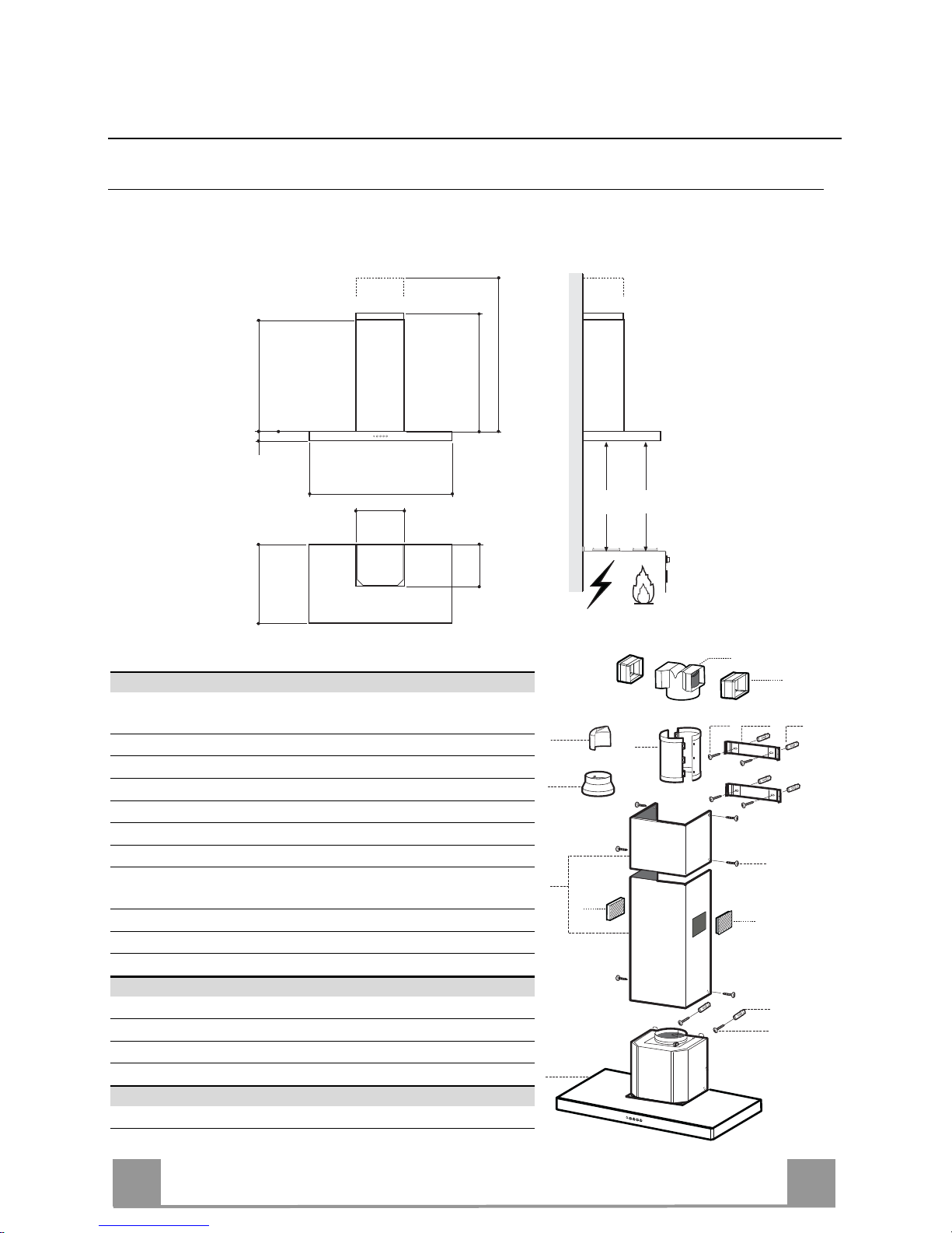
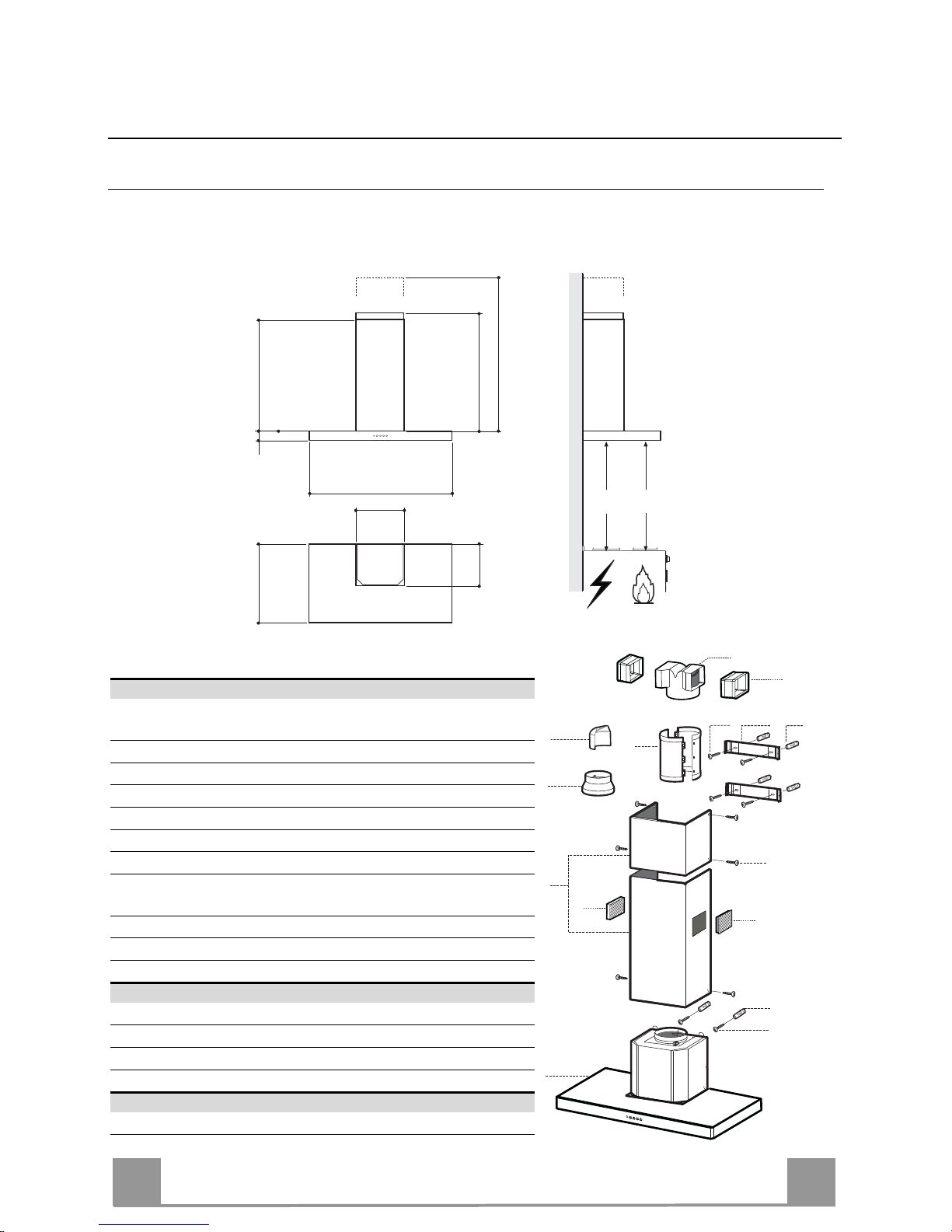
Ingombro
480
70
min. 745
max. 955
745
260
300
1098
Min.
650mm
Min.
650mm
Componenti
Rif. Q.tà Componenti di Prodotto
1 1 Corpo Cappa completo di: Comandi, Luce, Gruppo
Ventilatore, Filtri
2 1 Camino Telescopico formato da:
2.1 1 Camino Superiore
2.2 1 Camino Inferiore
8a 1 Griglia Direzionata DX Uscita Aria
8b 1 Griglia Direzionata SX Uscita Aria
9 1 Flangia di Riduzione ø 150-120 mm
14 1 Prolunga Uscita Aria Corpo Cappa formata da 2 Semi-
gusci
14.1 2 Prolunga Raccordo Uscita Aria
15 1 Raccordo Uscita Aria
16 1 Deflettore Uscita Aria
Rif. Q.tà Componenti di Installazione
7.2.1 2 Staffe Fissaggio Camino Superiore
11 6 Tasselli
12a 6 Viti 4,2 x 44,4
12c 6 Viti 2,9 x 9,5
Q.tà Documentazione
1 Libretto Istruzioni
2.1
2.2
2
12c
12a
7.2.1 11
11
12a
1
14.1
15
8a
9
16
8b
14
Page 6
IT
6
6
INSTALLAZIONE
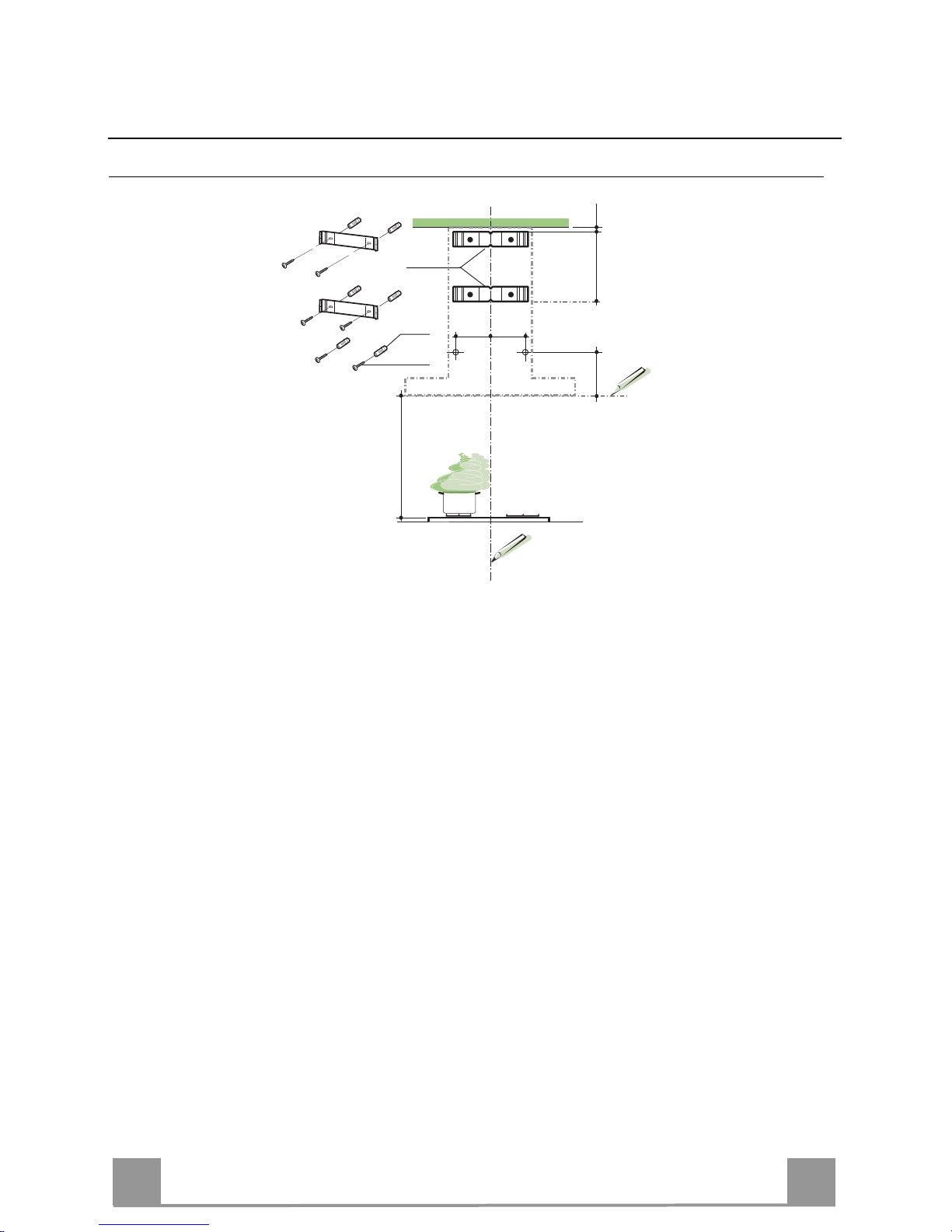
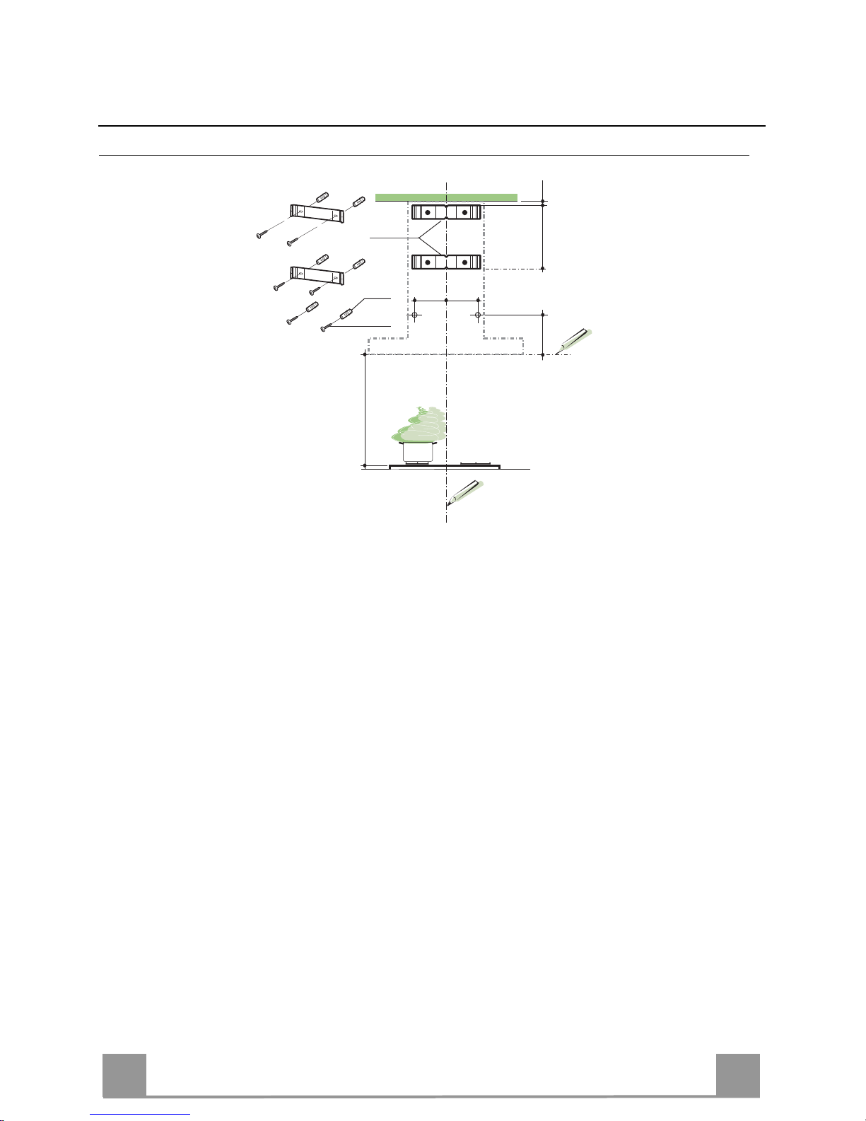
Foratura Parete e Fissaggio Staffe
11
12a
330
X
116
1÷2
116
650 min.
7.2.1
Tracciare sulla Parete:
• una linea Verticale fino al soffitto o al limite superiore, al centro della zona prevista per il
montaggio della Cappa;
• una linea Orizzontale a: 650 mm min. sopra il Piano di Cottura.
• Appoggiare come indicato la Staffa 7.2.1 a 1-2 mm dal soffitto o dal limite superiore, allineando il suo centro (intagli) sulla linea Verticale di riferimento.
• Segnare i centri dei Fori della Staffa.
• Appoggiare come indicato la Staffa 7.2.1 a X mm sotto la prima staffa (X = altezza Camino
Superiore in dotazione), allineando il suo centro (intagli) sulla linea Verticale di riferimento.
• Segnare i centri dei Fori della Staffa.
• Segnare come indicato, un punto di riferimento a 116 mm dalla linea Verticale di riferimento, e 330 mm sopra la linea Orizzontale di riferimento.
• Ripetere questa operazione dalla parte opposta.
• Forare ø 8 mm i punti segnati.
• Inserire i tasselli 11 nei fori.
• Fissare le Staffe, utilizzando le Viti 12a (4,2 x 44,4 ) in dotazione.
• Avvitare 2 Viti 12a (4,2 x 44,4) in dotazione nei fori per il fissaggio del corpo Cappa, lasciando uno spazio di 5-6 mm fra la parete e la testa della vite.
Page 7

IT
7
7
Montaggio Corpo Cappa
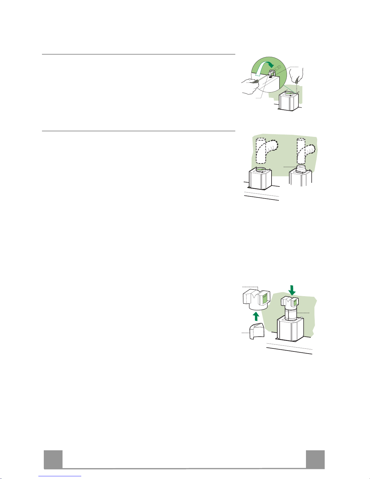
• Prima di agganciare il Corpo Cappa, serrare le 2 Viti Vr situate
sui punti di aggancio del Corpo Cappa.
• Agganciare il Corpo Cappa alle Viti 12a.
• Serrare definitivamente le Viti 12a di supporto.
• Agire sulle Viti Vr per livellare il Corpo Cappa.
12a
Vr
Connessioni
USCITA ARIA VERSIONE ASPIRANTE
Per installazione in Versione Aspirante collegare la Cappa alla
tubazione di uscita per mezzo di un tubo rigido o flessibile di
ø150 o 120 mm, la cui scelta è lasciata all'installatore.
• Per collegamento con tubo ø120 mm, inserire la Flangia di riduzione 9 sull’Uscita del Corpo Cappa.
• Fissare il tubo con adeguate fascette stringitubo. Il materiale
occorrente non è in dotazione.
• Togliere eventuali Filtri Antiodore al Carbone attivo.
9
ø 120ø 150
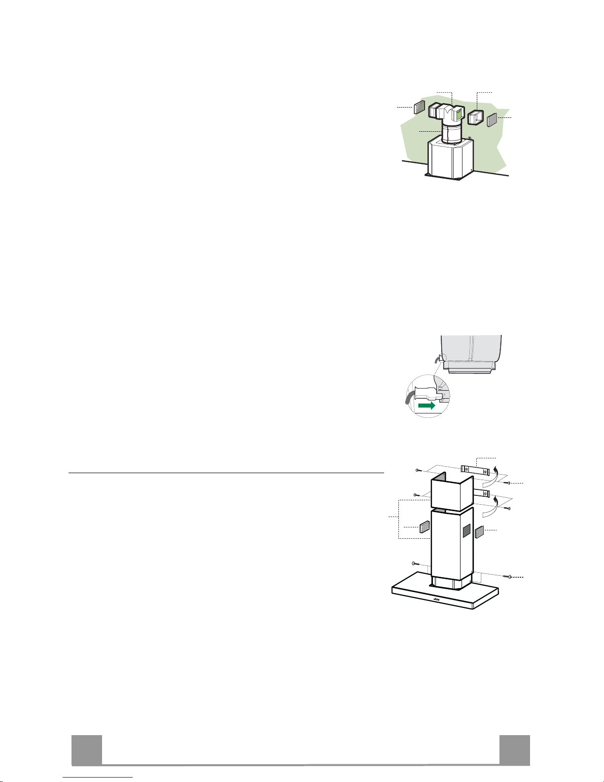
Uscita laterale aria Versione Aspirante (Collegamento soprapensile alla Tubazione di Uscita)
• Assemblare i semigusci della Prolunga Corpo Cappa 14.
• Inserire a pressione la Prolunga Corpo Cappa14 così ottenuta, sull’Uscita Aria.
• Inserire il Deflettore 16 nel Raccordo Uscita Aria 15 per
chiudere l’uscita non utilizzata.
• Inserire a pressione il Raccordo 15 sulla Prolunga Corpo
Cappa 14, assicurandosi che l’uscita libera risulti in corrispondenza della Bocchetta desiderata del Camino.
• Togliere gli eventuali Filtri antiodore al Carbone attivo.
15
16
14
Page 8
IT
8
8
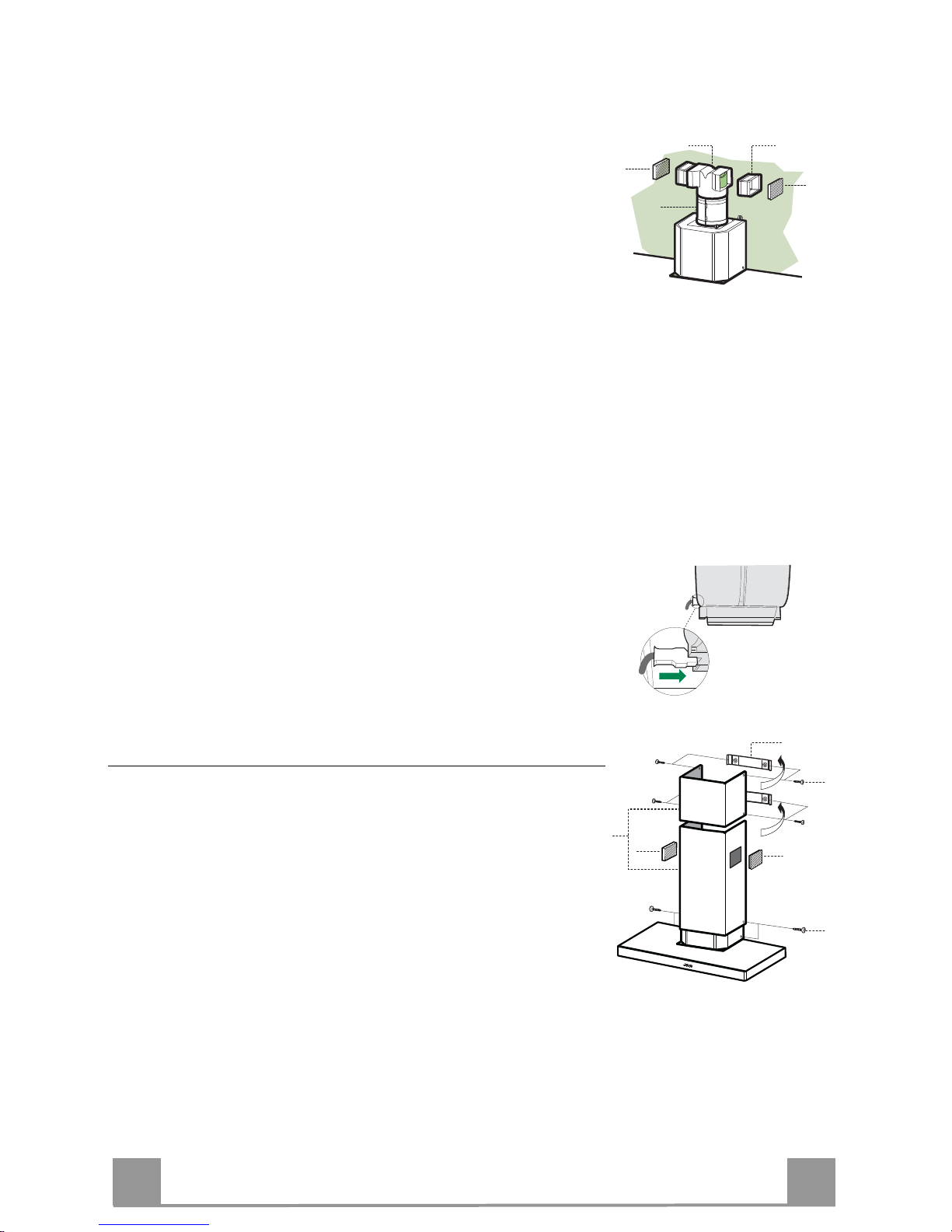
USCITA ARIA VERSIONE FILTRANTE
• Assemblare i Semigusci della Prolunga Corpo Cappa 14.
• Inserire a pressione la Prolunga Corpo Cappa 14 così ottenuta,
sull’Uscita Aria.
• Inserire a pressione il Raccordo 15 sulla Prolunga Corpo Cap-
pa 14.
• Inserire lateralmente le Prolunghe Raccordo 14.1 sul Raccordo
15.
• Assicurarsi che l’uscita delle Prolunghe Raccordo 14.1 risulti
in corrispondenza delle bocchette del Camino sia in orizzontale
che in verticale. Se così non fosse, aggiustare la posizione invertendo le Prolunghe Raccordo 14.1 o tagliando la Prolunga
Corpo Cappa 14 in corrispondenza di una delle lunghezze prestabilite dalle scanalature di minor spessore e rimontare i particolari come prima descritto.
• Le Griglie direzionate Uscita Aria 8a - 8b devono essere mon-
tate dopo l’installazione del Camino Inferiore 2.2.
• Assicurarsi della presenza del Filtro Antiodore al Carbone attivo.
14
14.115
8a
8b
CONNESSIONE ELETTRICA
• Collegare la Cappa all’Alimentazione di Rete interponendo un
Interruttore bipolare con apertura dei contatti di almeno 3 mm.
• Rimuovere i Filtri antigrasso (vedi par. “Manutenzione”) e assicurarsi che il connettore del Cavo di alimentazione sia correttamente inserito nella presa dell’Aspiratore
Montaggio Camino
Camino superiore
• Allargare leggermente le due falde laterali, agganciarle dietro
le Staffe 7.2.1 e richiuderle fino a battuta.
• Fissare lateralmente alle Staffe con 4 Viti 12c (2,9 x 9,5) in
dotazione.
Camino inferiore
• Allargare leggermente le due falde laterali del Camino, agganciarle tra il Camino superiore e la parete e richiuderle fino a
battuta.
• Fissare lateralmente la parte inferiore al Corpo Cappa, con 2
Viti 12c (2,9 x 9,5) in dotazione.
• Per la Versione Filtrante applicare le Griglie direzionate 8a 8b nelle apposite sedi, in modo che i simboli direzionali risultino orientati verso l’alto e il fronte della Cappa. Assicurarsi
inoltre che risultino inserite correttamente nelle Prolunghe
Raccordo 14.1.
12c
8a
2.1
2.2
2
8b
7.2.1
12c
Page 9

IT
9
9
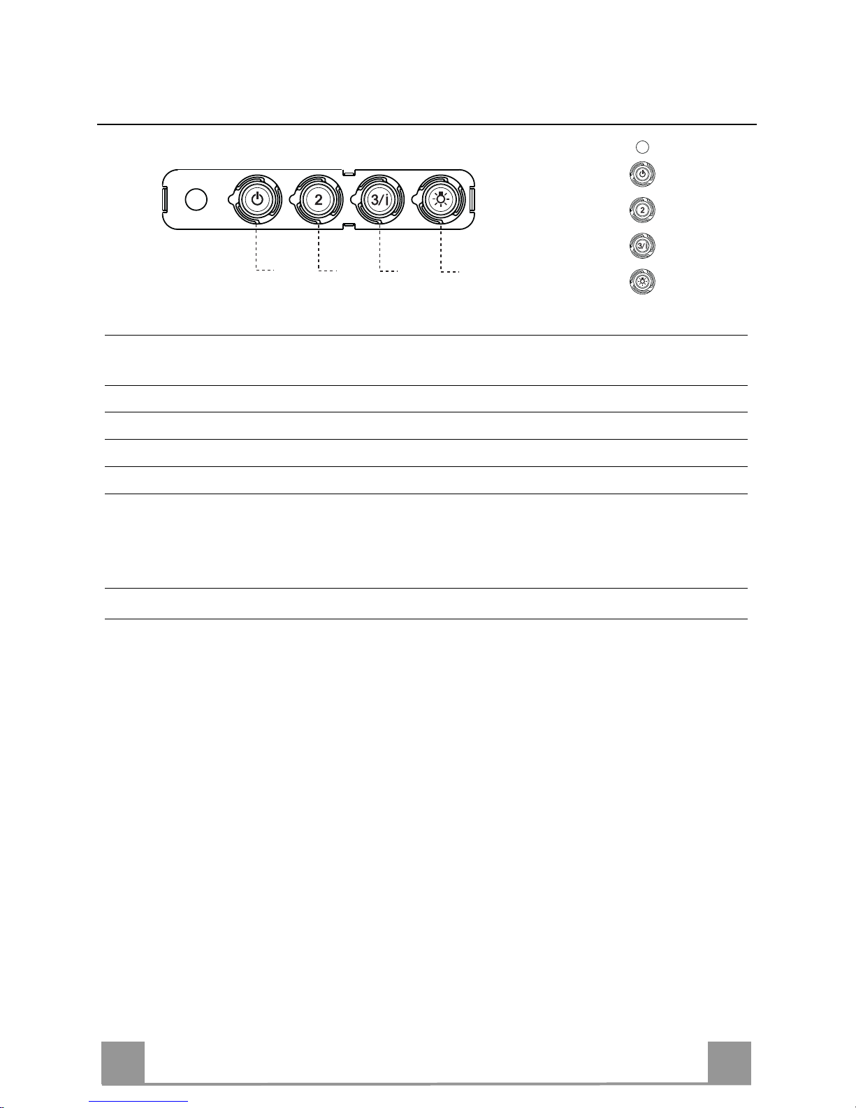
USO
T2
T1
L
T3
Quadro comandi
TASTO LED FUNZIONI
T1 Velocità Acceso Accende il Motore alla Prima velocità.
Spegne il Motore.
T2 Velocità Acceso Accende il Motore alla Seconda velocità.
T3 Velocità Fisso Premuto brevemente Accende il Motore alla Terza velocità.
Lampeggiante Premuto per 2 Secondi .
Attiva la Quarta velocità temporizzata a 10 minuti, al termine
dei quali ritorna alla velocità precedentemente impostata. Adatta a fronteggiare le massime emissioni di fumi di cottura.
L Luce Accende e spegne l’Impianto di Illuminazione.
Attenzione: Il tasto T1 spegne il motore passando sempre per la prima velocità.
Page 10
IT
1
10
MANUTENZIONE
Filtri antigrasso
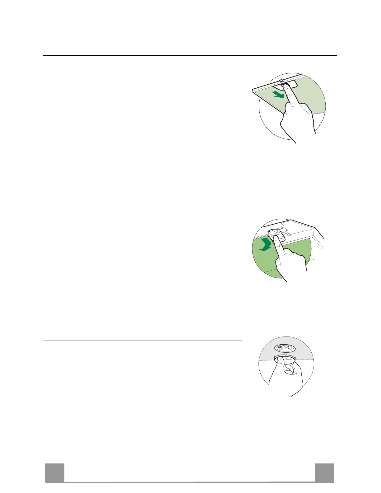
PULIZIA FILTRI ANTIGRASSO METALLICI AUTOPORTANTI
• Sono lavabili anche in lavastoviglie, e necessitano di essere
lavati ogni 2 mesi circa di utilizzo o più frequentemente, per un
uso particolarmente intenso.
• Togliere i Filtri uno alla volta, spingendoli verso la parte posteriore del gruppo e tirando contemporaneamente verso il basso.
• Lavare i Filtri evitando di piegarli, e lasciarli asciugare prima
di rimontarli.
• Rimontarli facendo attenzione a mantenere la maniglia verso la
parte visibile esterna.
Filtro antiodore (Versione Filtrante)
SOSTITUZIONE FILTRO ANTIODORE AL CARBONE ATTIVO
• Non è lavabile e non è rigenerabile, va sostituito almeno ogni 4
mesi o più frequentemente, per un uso particolarmente intenso.
• Togliere i Filtri antigrasso metallici.
• Rimuovere il Filtro antiodore al Carbone attivo saturo, agendo
sugli appositi agganci.
• Montare il nuovo Filtro agganciandolo nella sua sede.
• Rimontare i Filtri antigrasso metallici.
Illuminazione
SOSTITUZIONE LAMPADE
Lampade alogene da 20 W
• Togliere il bloccavetro metallico a pressione facendo leva sotto
la ghiera, sostenendolo con una mano.
• Estrarre la lampadina alogena dal portalampada.
• Sostituirla con una nuova lampadina di uguali caratteristiche,
facendo attenzione ad inserire correttamente i due spinotti nella
sede del portalampade.
• Rimontare il bloccavetro a pressione.
Page 11

EN
1
11
RECOMMENDATIONS AND SUGGESTIONS
The Instructions for Use apply to several versions of this appliance. Accord-
ingly, you may find descriptions of individual features that do not apply to
your specific appliance.
INSTALLATION
• The manufacturer will not be held liable for any damages resulting from in-
correct or improper installation.
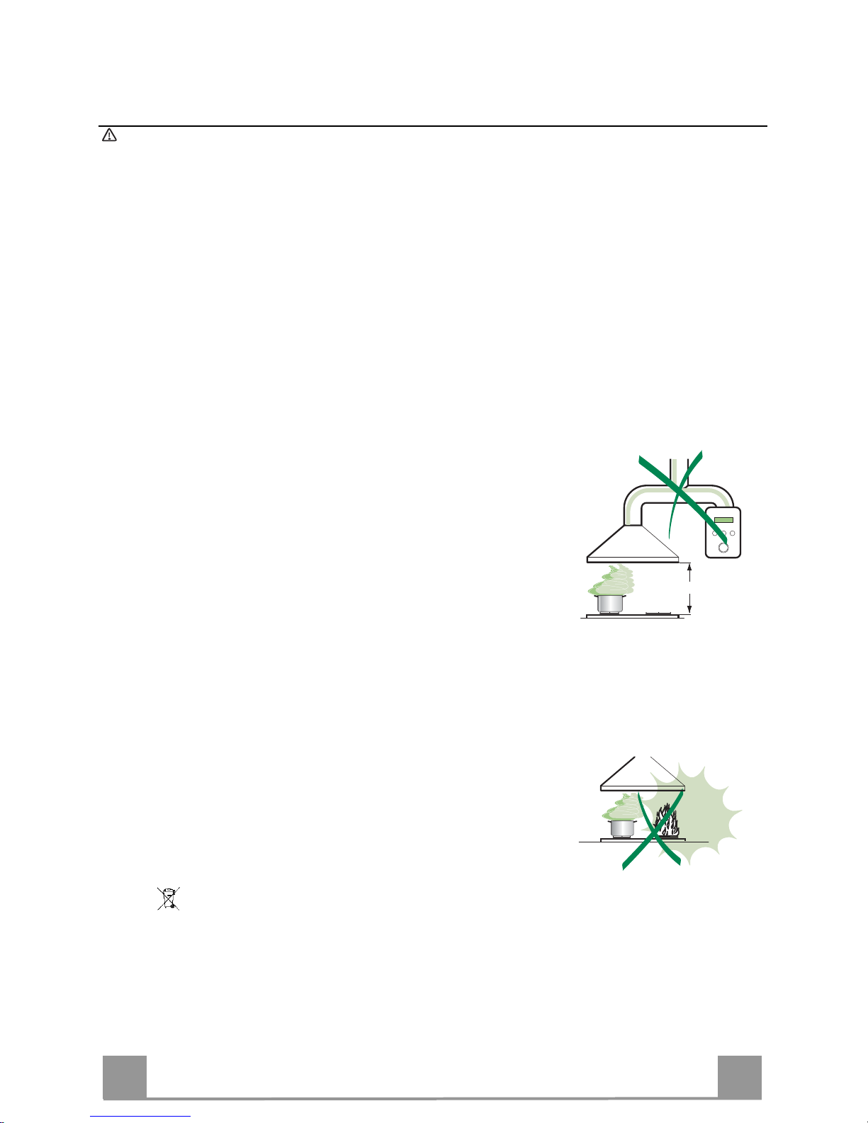
• The minimum safety distance between the cooker top and the extractor
hood is 650 mm (some models can be installed at a lower height, please refer to the paragraphs on working dimensions and installation).
• Check that the mains voltage corresponds to that indicated on the rating
plate fixed to the inside of the hood.
• For Class I appliances, check that the domestic power supply guarantees
adequate earthing.
Connect the extractor to the exhaust flue through a pipe of minimum diame-
ter 120 mm. The route of the flue must be as short as possible.
• Do not connect the extractor hood to exhaust ducts carrying combustion
fumes (boilers, fireplaces, etc.).
• If the extractor is used in conjunction with non-electrical appliances (e.g. gas
burning appliances), a sufficient degree of aeration must be guaranteed in
the room in order to prevent the backflow of exhaust gas. The kitchen must
have an opening communicating directly with the open air in order to
guarantee the entry of clean air.
USE
• The extractor hood has been designed exclusively for domestic use to elimi-
nate kitchen smells.
• Never use the hood for purposes other than for which it has been designed.
• Never leave high naked flames under the hood when it is in operation.
• Adjust the flame intensity to direct it onto the bottom of the pan only, making
sure that it does not engulf the sides.
• Deep fat fryers must be continuously monitored during use: overheated oil
can burst into flames.
• Do not flambè under the range hood; risk of fire
• This appliance is not intended for use by persons (including children) with
reduced physical, sensory or mental capabilities, or lack of experience and
knowledge, unless they have been given supervision or instruction con cern-
ing use of the appliance by a person responsible for their safety.
• Children should be supervised to ensure that they do not play with the appli-
ance.
MAINTENANCE
• Switch off or unplug the appliance from the mains supply before carrying out
any maintenance work.
• Clean and/or replace the Filters after the specified time period (Fire hazard).
• Clean the hood using a damp cloth and a neutral liquid detergent.
The symbol on the product or on its packaging indicates that this product may not be treated
as household waste. Instead it shall be handed over to the applicable collection point for the
recycling of electrical and electronic equipment. By ensuring this product is disposed of correctly,
you will help prevent potential negative consequences for the environment and human health,
which could otherwise be caused by inappropriate waste handling of this product. For more
detailed information about recycling of this product, please contact your local city office, your
household waste disposal service or the shop where you purchased the product.
650 mm min.
Page 12
EN
1
12
CHARACTERISTICS
Dimensions
480
70
min. 745
max. 955
745
260
300
1098
Min.
650mm
Min.
650mm
Components
Ref. Q.ty Product Components
1 1 Hood Body, complete with: Controls, Light, Blower,
Filters
2 1 Telescopic Chimney comprising:
2.1 1 Upper Section
2.2 1 Lower Section
8a 1 Right Air Outlet Grill
8b 1 Left Air Outlet Grill
9 1 Reducer Flange ø 150-120 mm
14 1 Hood Body Air Outlet Extension Piece consisting of two
Half Shells
14.1 2 Air Outlet Connection Extension
15 1 Air Outlet Connection
16 1 Air Outlet Deflector
Ref. Q. ty Installation Components
7.2.1 2 Upper Chimney Section Fixing Brackets
11 6 Wall Plugs
12a 6 Screws 4,2 x 44,4
12c 6 Screws 2,9 x 9,5
Q.ty Documentation
1 Instruction Manual
2.1
2.2
2
12c
12a
7.2.1 11
11
12a
1
14.1
15
8a
9
16
8b
14
Page 13
EN
1
13
INSTALLATION
Wall drilling and bracket fixing
11
12a
330
X
116
1÷2
116
650 min.
7.2.1
Wall marking:
• Draw a vertical line on the supporting wall up to the ceiling, or as high as practical, at the
centre of the area in which the hood will be installed.
• Draw a horizontal line at 650 mm above the hob. Place bracket 7.2.1 on the wall as shown
about 1-2 mm from the ceiling or upper limit aligning the centre (notch) with the vertical
reference line.
• Mark the wall at the centres of the holes in the bracket.
• Place bracket 7.2.1 on the wall as shown at X mm below the first bracket (X = height of the
upper chimney section supplied), aligning the centre (notch) with the vertical line.
• Mark the wall at the centres of the holes in the bracket.
• Mark a reference point as indicated at 116 mm from the vertical reference line and 330 mm
above the horizontal reference line.
• Repeat this operation on the other side.
• Drill ø 8 mm holes at all the centre points marked.
• Insert the wall plugs 11 in the holes.
• Fix the brackets using the 12a (4,2 x 44,4) screws supplied.
• Insert the two screws 12a (4,2 x 44,4) supplied in the hood body fixing holes, leaving a gap
of 5-6 mm between the wall and the head of the screw.
Page 14
EN
1
14
Mounting the hood body
• Before attaching the hood body, tighten the two screws Vr located on the hood body mounting points.
• Hook the hood body onto the screws 12a.
• Fully tighten the support screws 12a.
• Adjust the screws Vr to level the hood body.
12a
Vr
Connections
DUCTED VERSION AIR EXHAUST SYSTEM
When installing the ducted version, connect the hood to the
chimney using either a flexible or rigid pipe ø 150 or 120 mm,
the choice of which is left to the installer.
• To install a ø 120 mm air exhaust connection, insert the reducer flange 9 on the hood body outlet.
• Fix the pipe in position using sufficient pipe clamps (not supplied).
• Remove possible charcoal filters.
9
ø 120ø 150
Lateral air exhaust on ducted version (connection to exhaust flue above wall cupboards)
• Assemble the half-shells of the hood body extension piece
14.
• Push fit the assembled hood body extension 14 onto the air
exhaust outlet.
• Insert the deflector 16 into the air exhaust fitting 15 to close
off the unused outlet.
• Push fit connection piece 15 to the hood body
extension piece 14, ensuring that the free end
matches up with the opening of the required outlet duct.
• Remove any activated charcoal filters.
15
16
14
Page 15
EN
1
15
RECIRCULATION VERSION AIR OUTLET
• Assemble the two halves of the hood body extension piece 14.
• Push fit the assembled hood body extension piece 14 onto the
air outlet.
• Push fit connection 15 onto the hood body extension piece 14.
• Insert the connection extension pieces laterally 14.1 in connection 15.
• Make sure that the outlet of the extension pieces 14.1 is hori-
zontally and vertically aligned with the chimney outlets. If this
is not the case, adjust the position by either reversing the connection extension pieces 14.1 or by cutting the hood body extension 14 along one of the thinner section channels denoting
the pre-fixed lengths, then reassemble as described previously.
• The air outlet directional grills 8a - 8b must be fitted after the
lower outlet duct has been installed.
• Ensure that the activated charcoal filters have been inserted.
14
14.115
8a
8b
ELECTRICAL CONNECTION
• Connect the hood to the mains through a two-pole switch having a contact gap of at least 3 mm.
• Remove the grease filters (see paragraph Maintenance) being
sure that the connector of the feeding cable is correctly inserted
in the socket placed on the side of the fan.
Flue assembly
Upper exhaust flue
• Slightly widen the two sides of the upper flue and hook them
behind the brackets 7.2.1, making sure that they are well
seated.
• Secure the sides to the brackets using the 4 screws 12c (2,9 x
9,5) supplied.
Lower exhaust flue
• Slightly widen the two sides of the flue and hook them between the upper flue and the wall, making sure that they are
well seated.
• Fix the lower part laterally to the hood body using the 2 screws
12c (2,9 x 9,5) supplied.
• On the recirculation version, fit the directional grids 8a – 8 b in
their housings making sure that the directional symbols are towards the top and front of the hood. Also make sure that they
are correctly inserted in the connection extension pieces 14.1.
12c
8a
2.1
2.2
2
8b
7.2.1
12c
Page 16
EN
1
16
USE
T2
T1
L
T3
Control panel
BUTTON LED FUNCTIONS
T1 Speed On Turns the Motor on at Speed one.
Turns the Motor off.
T2 Speed On Turns the Motor on at Speed two.
T3 Speed Fixed When pressed briefly, turns the Motor on at Speed three.
Flashing Pressed for 2 Seconds.
Activates Speed four with a timer set to 10 minutes, after
which it returns to the speed that was set previously. Suitable
to deal with maximum levels of cooking fumes.
L Light Turns the Lighting System on and off.
Warning: Button T1 turns the motor off, after first passing to speed one.
Page 17

EN
1
17
MAINTENANCE
Grease filters
CLEANING METAL SELF- SUPPORTING GREASE FILTERS
• The filters must be cleaned every 2 months of operation, or
more frequently for particularly heavy usage, and can be
washed in a dishwasher.
• Remove the filters one at a time by pushing them towards the
back of the group and pulling down at the same time.
• Wash the filters, taking care not to bend them. Allow them to
dry before refitting.
• When refitting the filters, make sure that the handle is visible
on the outside.
Activated charcoal filter (Recirculation version)
REPLACING THE ACTIVATED CHARCOAL FILTER
• The filter is not washable and cannot be regenerated, and must
be replaced approximately every 4 months of operation, or
more frequently for particularly heavy usage.
• Remove t h e metal grease filters.
• Remove the saturated activated carbon filter by releasing the
fixing hooks.
• Fit the new filter by hooking it into its seating.
• Refit the metal grease filters.
Lighting
LIGHT REPLACEMENT
20 W halogen light.
• Remove the snap-on lamp cover by levering it from under the
metal ring, supporting it with one hand.
• Remove the halogen lamp from the lamp holder by pulling
gently.
• Replace the lamp with a new one of the same type, making
sure that you insert the two pins properly into the housings on
the lamp holder.
• Replace the snap-on lamp cover.
Page 18
FR
1
18
CONSEILS ET SUGGESTIONS
La présente notice d'emploi vaut pour plusieurs versions de l'appareil. Elle peut conte-
nir des descriptions d'accessoires ne figurant pas dans votre appareil.
INSTALLATION
• Le fabricant décline toute responsabilité en cas de dommage dû à une installation non
correcte ou non conforme aux règles de l’art.
• La distance minimale de sécurité entre le plan de cuisson et la hotte doit être de 650
mm au moins (certains modèles peuvent être installés à une hauteur inférieure : se reporter aux paragraphes « Encombrement » et « Installation »).
• Vérifier que la tension du secteur correspond à la valeur qui figure sur la plaquette
apposée à l’intérieur de la hotte.
• Pour les Appareils appartenant à la Ière Classe, veiller à ce que la mise à la terre de
l’installation électrique domestique ait été effectuée conformément aux normes en vi-
gueur.
• Connecter la hotte à la sortie d’air aspiré à l’aide d’une tuyauterie d’un diamètre égal ou
supérieur à 120 mm. Le parcours de la tuyauterie doit être le plus court possible.
• Ne pas connecter la hotte à des conduites d’évacuation de fumées issues d’une combustion tel que (Chaudière, cheminée, etc…).
• Si vous utilisez des appareils qui ne fonctionnent pas à l’électricité dans la pièce ou est
installée la hotte (par exemple: des appareils fonctionnant au gaz), vous devez prévoir
une aération suffisante du milieu. Si la cuisine en est dépourvue, pratiquez une ouverture qui communique avec l’extérieur pour garantir l’infiltration de l’air pur.
UTILISATION
• La hotte a été conçue exclusivement pour l’usage domestique, dans le but d’éliminer
les odeurs de la cuisine.
• Ne jamais utiliser abusivement la hotte.
• Ne pas laisser les flammes libres à forte intensité quand la hotte est en service.
• Toujours régler les flammes de manière à éviter toute sortie latérale de ces dernières
par rapport au fond des marmites.
• Contrôler les friteuses lors de l’utilisation car l’huile surchauffée pourrait s’enflammer.
• Ne pas préparer d’aliments flambés sous la hotte de cuisine : risque d’incendie
• Cet appareil ne doit pas être utilisé par des personnes (y compris les enfants) ayant
des capacités psychiques, sensorielles ou mentales réduites, ni par des personnes
n’ayant pas l’expérience et la connaissance de ce type d’appareils, à moins d'être sous
le contrôle et la formation de personnes responsables de leur sécurité.
• Les enfants doivent être surveillés pour s'assurer qu'ils ne jouent pas avec l'appareil.
ENTRETIEN
• Avant de procéder à toute opération d’entretien, débrancher la hotte en retirant la fiche
ou en actionnant l’interrupteur général.
• Effectuer un entretien scrupuleux et en temps dû des Filtres, à la cadence conseillée
(Risque d’incendie).
• Pour le nettoyage des surfaces de la hotte, il suffit d’utiliser un chiffon humide et détersif liquide neutre.
Le symbole sur le produit ou son emballage indique que ce produit ne peut être traité comme
déchet ménager. Il doit plutôt être remis au point de ramassage concerné, se chargeant du recyclage du matériel électrique et électronique. En vous assurant que ce produit est éliminé correctement, vous favorisez la prévention des conséquences négatives pour l’environnement et la santé
humaine qui, sinon, seraient le résultat d’un traitement inapproprié des déchets de ce produit. Pour
obtenir plus de détails sur le recyclage de ce produit, veuillez prendre contact avec le bureau municipal de votre région, votre service d’élimination des déchets ménagers ou le magasin où vous avez
acheté le produit.
650 mm min.
Page 19

FR
1
19
CARACTERISTIQUES
Encombrement
480
70
min. 745
max. 955
745
260
300
1098
Min.
650mm
Min.
650mm
Composants
Réf. Q.té Composants de Produit
1 1 Corps Hotte équipé de:Comandes,
Lumière,Groupe Ventilateur,Filtres
2 1 Cheminée Télescopique formée de :
2.1 1 Cheminée Supérieure
2.2 1 Cheminée Inférieure
8a 1 Grille en Direction Droite Sortie Air
8b 1 Grille en Direction Gauche Sortie Air
9 1 Flasque de Réduction ø 150-120 mm
14 1 Rallonge Sortie Air Corps Hotte formée de 2 Semi-
Coques
14.1 1 Rallonge Raccord Sortie Air
15 1 Raccord Sortie Air
16 1 Déflecteur Sortie Air
Réf. Q.té Composants pour l ’installation
7.2.1 2 Brides Fixation Cheminée Supérieure
11 6 Chevilles
12a 6 Vis 4,2 x 44,4
12c 6 Vis 2,9 x 9,5
Q.té Documentation
1 Manuel d’instructions
2.1
2.2
2
12c
12a
7.2.1 11
11
12a
1
14.1
15
8a
9
16
8b
14
Page 20

FR
2
20
INSTALLATION
Perçage Paroi et Fixation Brides
11
12a
330
X
116
1÷2
116
650 min.
7.2.1
Tracer sur la paroi:
• une ligne verticale allant jusqu’au plafond ou à la limite supérieure, au centre de la zone
prévue pour le montage de la hotte;
• une ligne horizontale à 650 mm min. au-dessus du plan de cuisson.
• Poser comme indiqué une bride 7.2.1 sur la paroi à 1-2 mm du plafond ou de la limite supérieure, en alignant son centre (découpes) sur la ligne verticale de repère.
• Marquer les centres de s tr ous rainurés de la bride.
• Poser comme indiqué la bride 7.2.1 à X mm sous la première bride (X = hauteur cheminée
supérieure fournie), en alignant son centre (découpes) sur la ligne verticale de repère.
• Marquer les centres de s tr ous rainurés de la bride.
• Marquer comme indiqué, un point de référence à 116 mm de la ligne verticale de repère, et
330 mm au-dessus de la ligne horizontale de repère.
• Répéter cette opération sur le côté opposé.
• Percer de ø 8 mm tous les points marqués.
• Insérer les chevilles 11 dans les trous.
• Fixer les brides en utilisant les vis 12a (4,2 x 44,4) fournies.
• Visser les 2 vis 12a (4,2 x 44,4) fournies dans les trous de fixation du corps hotte, en laissant
un espace de 5-6 mm entre le mur et la tête de la vis.
Page 21

FR
2
21
Montage Corps Hotte
• Avant d’accrocher le corps hotte, serrer les deux vis Vr situées
sur les points d’accrochage du corps hotte.
• Accrocher le corps hotte aux vis 12a prévues à cet effet.
• Serrer définitivement les vis 12a de support.
• Agir sur les vis Vr pour niveler le corps hotte.
12a
Vr
Branchements
SORTIE AIR VERSION ASPIRANTE
En cas d’installation en version aspirante, brancher la hotte à la
tuyauterie de sortie via un tube ri-gide ou flexible de ø 150 ou
120 mm, au choix de l’installateur.
• En cas de branchement avec un tube de ø120 mm, insérer le
flasque de réduction 9 sur la sortie du corps de la hotte.
• Fixer le tube par des colliers appropriés. Le matériau nécessaire n’est pas fourni.
• Retirer les éventuels filtres anti-odeur au charbon actif.
9
ø 120ø 150
Sortie latérale air version aspirante (raccordement à la
tuyauterie de sortie en dessus des éléments suspendus)
• Assembler les demi-coques de la rallonge corps hotte 14.
• Insérer sous pression la rallonge hotte 14 ainsi obtenue dans
la sortie d’air.
• Insérer le déflecteur 16 dans le raccord sortie air 15 pour
fermer la sortie non utilisée.
• De la même façon, appliquer le raccord 15 sur la rallonge
corps hotte 14, en s’assurant que la sortie libre soit au niveau
de la bouche de la cheminée souhaitée.
• Retirer les éventuels filtres anti-odeur au charbon actif.
15
16
14
Page 22

FR
2
22
SORTIE AIR VERSION FILTRANTE
• Assembler les semi-coques de la rallonge corps hotte 14.
• Insérer sous pression la rallonge corps hotte 14 ainsi obtenue, à
la sortie air.
• Insérer sous pression le raccord 15 sur la rallonge corps hotte
14.
• Insérer latéralement les rallonges raccord 14.1 sur le raccord
15.
• S’assurer que la sortie des rallonges raccord 14.1 se trouve au
niveau des bouches de la cheminée aussi bien en horizontal
qu’en vertical.
• Si tel n’est pas le cas, ajuster la position en inversant les rallonges raccord 14.1 ou en coupant la rallonge corps hotte 14 au
niveau d’une des longueurs prédéfinies par les rainures moins
épaisses et remonter les pièces comme décrit au préalable.
• Les grilles 8a - 8b en direction sortie air doivent être montées
après l’installation de la cheminée inférieure.
• S’assurer de la présence des filtres anti-odeur au charbon actif.
14
14.115
8a
8b
BRANCHEMENT ELECTRIQUE
• Brancher la hotte sur le secteur en interposant un interrupteur
bipolaire avec ouverture des contacts d’au moins 3 mm.
• Enlever les filtres à graisse (voir § "Entretien") et s'assurer que
le connecteur du câble d'alimentation soit bien branché dans la
prise du diffuseur.
Montage Cheminée
Cheminée supérieure
• Elargir légèrement les deux bords latériaux, et les accrocher
derrières les brides 7.2.1 ; refermer jusqu’à la butée.
• Fixer latéralement aux brides à l’aide des 4 vis 12c (2,9 x 9,5)
fournies.
Cheminée inférieure
• Elargir légèrement les deux bords latériaux de la Cheminée et
les accrocher entre la Cheminée supérieure et la paroi; refermer
jusqu’à la butée.
• Fixer latéralement la partie inférieure au corps hotte, à l’aide
des deux 2 vis 12c (2,9 x 9,5) fournies.
• Pour la version filtrante, appliquer les grilles en direction 8a – 8b
dans les logements appropriés, pour que les symboles de direction soient orientés vers le haut et la partie avant de la hotte.
S’assurer également qu’elles sont bien insérées dans les rallonges raccord 14.1.
12c
8a
2.1
2.2
2
8b
7.2.1
12c
Page 23

FR
2
23
UTILISATION
T2
T1
L
T3
Tableau des commandes
TOUCHE VOYANT FONCTIONS
T1 Vitesse Allumé Démarre le moteur en première vitesse.
Coupe le moteur.
T2 Vitesse Allumé Démarre le moteur en deuxième vitesse.
T3 Vitesse Fixe Appuyée brièvement, démarre le moteur en troisième vitesse.
Clignotant Appuyée pendant 2 secondes.
Démarre la quatrième vitesse avec une temporisation de 10 mi-
nutes, après lesquelles le moteur retourne à la vitesse précédemment programmée. Fonction indiquée pour faire face aux pointes
d’émission de fumées de cuisson.
L Lumière Branche et débranche l’éclairage.
Attention : La touche T1 coupe le moteur en passant toujours par la première vitesse.
Page 24

FR
2
24
ENTRETIEN
Filtres anti-graisse
NETTOYAGE FILTRES ANTI-GRAISSE METALLIQUES AUTOPORTEURS
• Lavables au lave-vaisselle, ils doivent être lavés environ tous
les 2 mois d’emploi ou plus fréquemment en cas d’emploi particulièrement intense.
• Retirer les filtres l’un aprés l’autre, en les poussant vers la partie arrière du groupe et en tirant simultanément vers le bas.
• Laver les filtres en évitant de les plier et les laisser sécher avant
de les remonter.
• Remonter les filtres en veillant à ce que la poignée reste vers la
partie visible externe
Filtre anti-odeur (Version filtrante)
REMPLACEMENT FILTRE AU CHARBON ACTIF
• Ni lavable, ni régénérable, le remplacer au moins tous les 4
mois d’emploi ou plus fréquemment en cas d’emploi particulièrement intense.
• Retirer les filtres anti-graisse métalliques.
• Retirer le filtre anti-odeur au charbon actif colmaté, en agissant
sur les crochets prévus à cet effet.
• Monter le nouveau filtre anti-odeur au charbon actif.
• Remonter les filtres anti-graisse métalliques.
Eclairage
REMPLACEMENT LAMPES
Lampe halogène de 20 W.
• Enlever le dispositif métallique de blocage du verre par encliquetage en exerçant une pression sous l’embout en le soutenant
d’une main.
• Extraire la lampe du support
• Remplacer la lampe par une nouvelle ayant le mêmes caractéristiques, en prenant soin d'insérer correctement les deux fiches
dans le support.
• Remonter le dispositif de blocage du verre par encliquetage.
Page 25

DE
2
25
EMPFEHLUNGEN UND HINWEISE
Diese Gebrauchsanleitung gilt für mehrere Geräte-Ausführungen. Es ist möglich, dass
einzelne Ausstattungsmerkmale beschrieben sind, die nicht auf Ihr Gerät zutreffen.
MONTAGE
• Der Hersteller haftet nicht für Schäden, die auf eine fehlerhafte und unsachgemäße
Montage zurückzuführen sind.
• Der minimale Sicherheitsabstand zwischen Kochmulde und Haube muss 650 mm
betragen (einige Modelle können an einer geringeren Höhe installiert werden, beziehen
Sie sich dazu auf den Absatz Raumbedarf und Installation).
• Prüfen, ob die Netzspannung mit dem Wert auf dem im Haubeninneren angebrachten
Schild übereinstimmt.
• Bei Geräten der Klasse I ist sicherzustellen, dass die elektrische Anlage des Wohnhauses über eine vorschriftsmäßige Erdung verfügt.
• Das Anschlussrohr der Haube zur Luftaustrittsöffnung muss einen Durchmesser von
120 mm oder darüber aufweisen. Der Rohrverlauf muss so kurz wie möglich sein.
• Die Haube darf an keine Entlüftungsschächte angeschlossen werden, in die Verbrennungsgase (Heizkessel, Kamine usw.) geleitet werden.
• Werden im Raum außer der Dunstabzugshaube andere, nicht elektrisch betriebene
(z.B. gasbetriebene) Geräte verwendet, muss für eine ausreichende Belüftung gesorgt
werden. Sollte die Küche diesbezüglich nicht entsprechen, ist an einer Aussenwand
eine Öffnung anzubringen, die Frischluftzufuhr gewährleistet.
BEDIENUNG
• Die Dunstabzugshaube ist ausschließlich zum Einsatz im privaten Haushalt und zur
Beseitigung von Küchengerüchen vorgesehen.
• Unsachgemäßer Einsatz der Haube ist zu unterlassen.
• Große Flammen bei eingeschalteter Haube niemals unbedeckt lassen.
• Die Intensivität der Flamme ist so zu regulieren, dass sie den Topfboden nicht über-
ragt.
• Frittiergeräte müssen während des Gebrauchs stets beaufsi chtigt werden: überhitztes
Öl kann sich entzünden.
• Keine flambierten Speisen unter der Abzugshaube zubereiten: Brandgefahr.
• Dieses Gerät darf nicht von Personen, auch Kindern, mit verminderten psychischen,
sensorischen und geistigern Fähigkeiten, oder von Personen ohne Erfahrung und
Kenntnisse benutzt werden, sofern sie nicht von für ihre Sicherheit verantwortlichen
Personen beaufsichtigt und beim Gebrauch des Geräts angeleitet werden.
• Kinder dürfen sich nicht unbeaufsichtigt in der Nähe des Geräts aufhalten und auf
keinen Fall mit dem Gerät spielen.
WARTUNG
• Bevor Wartungsarbeiten durchgeführt werden, muss die Stromzufuhr zur Haub e unte r-
brochen werden, indem der Stecker gezogen oder der Hauptschalter abgeschaltet
wird.
• Bei der Filterwartung müssen die vom Hersteller empfohlenen Zeiträume zum Austauschen der Filter genauestens eingehalten werden (Brandgefahr).
• Zur Reinigung der Haubenflächen Wir empfehlen ein feuchtes Tuch und ein mildes
Flüssigreinigungsmittel.
Das Symbol auf dem Produkt oder seiner Verpackung weist darauf hin, dass dieses Produkt nicht
als normaler Haushaltsabfall zu behandeln ist, sondern an einem Sammelpunkt für das Recycling von
elektrischen und elektronischen Geräten abgegeben werden muss. Durch Ihren Beitrag zum korrekten
Entsorgen dieses Produkts schützen Sie die Umwelt und die Gesundheit Ihrer Mitmenschen. Umwelt
und Gesundheit werden durch falsches Entsorgen gefährdet. Weitere Informationen über das Recycling
dieses Produkts erhalten Sie von Ihrem Rathaus, Ihrer Müllabfuhr oder dem Geschäft, in dem Sie das
Produkt gekauft haben.
650 mm min.
Page 26

DE
2
26
CHARAKTERISTIKEN
Platzbedarf
480
70
min. 745
max. 955
745
260
300
1098
Min.
650mm
Min.
650mm
Komponenten
Pos. St. Produktkomponenten
1 1 Haubenkörper mit Schaltern,Beleuchtung,
Gebläsegruppe,Filter
2 1 Teleskopkamin bestehend aus:
2.1 1 oberer Kaminteil
2.2 1 unterer Kaminteil
8a 1 Luftleitgitter Luftaustritt rechts
8b 1 Luftleitgitter Luftaustritt links
9 1 Reduzierflansch ø 150-120 mm
14 1 Verlängerungsstück f.Luftaustritt Hauben-
körper,bestehend aus 2 Rohrhälften
14.1 2 Verlängerung Luftaustritt-Anschlussstück
15 1 Luftaustritt-Anschlussstück
16 1 Luftaustritt-Deflektor
Pos. St. Montagekomponenten
7.2.1 2 Befestigungsbügel oberer Kaminteil
11 6 Bügel
12a 6 Schrauben 4,2 x 44,4
12c 6 Schrauben 2,9 x 9,5
St. Dokumentation
1 Bedienungsanleitung
2.1
2.2
2
12c
12a
7.2.1 11
11
12a
1
14.1
15
8a
9
16
8b
14
Page 27

DE
2
27
MONTAGE
Bohren der Befestigungslöcher und Fixieren der Befestigungsbügel
11
12a
330
X
116
1÷2
116
650 min.
7.2.1
Nachstehende Linien an die Wand zeichnen:
• eine vertikale Linie bis zur Decke oder oberen Begrenzung, und zwar in der Mitte des Bereiches, in dem die Haube montiert werden soll;
• eine horizontale Linie mit einem minimalen Abstand von 650 mm zur Kochfläche.
• Einen Bügel 7.2.1 zirka 1-2 mm unter der Decke oder oberen Begrenzung an die Wand legen und seinen Mittelpunkt (Einschnitte) auf die vertikale Bezugslinie ausrichten.
• Die Mitte der beiden Bügellöcher an der Wand markieren.
• Den zweiten Bügel 7.2.1 an die Wand legen, wobei ein Abstand X mm vom oberen Bügel
einzuhalten ist (X = Höhe des jeweiligen oberen Kaminteils); den Mittelpunkt (Einschnitte)
auf die vertikale Bezugslinie ausrichten.
• Die Mitte der Bügellöcher an der Wand markieren.
• Wie beschrieben einen Bezugspunkt 116 mm von der vertikalen Bezugslinie und 330 mm
oberhalb der horizontalen Bezugslinie kennzeichnen.
• Gleichermaßen an der gegenüberliegenden Seite vorgehen.
• Mit einem Bohrer ø 8 mm die markierten Punkte bohren.
• Die Dübel 11 in die Bohrungen einfügen.
• Die Bügel mit den mitgelieferten Schrauben 12a (4,2 x 44,4) fixieren.
• 2 der mitgelieferten Schrauben 12a (4,2 x 44,4) bei den Befestigungslöchern des Haubenkörpers einschrauben, wobei zwischen Wand und Schraubenkopf ein Freiraum von 5-6 mm
zu belassen ist.
Page 28

DE
2
28
Montage des Haubenkörpers
• Bevor der Haubenkörper eingehakt wird, die 2 Schrauben Vr
bei den Haubenkörper-Anhakpunkten festziehen.
• Den Haubenkörper bei den Schrauben 12a einhängen.
• Die Halteschrauben 12a definitiv festziehen.
• Den Haubenkörper mit Hilfe der Schrauben Vr ausrichten.
12a
Vr
Anschlüss in abluftversion
Bei Abluftbetrieb kann die Haube vom Installateur wahlweise
mittels Rohr oder Schlauch (ø 150 oder 120 mm) an die Außenrohrleitung angeschlossen werden.
• Bei Verwendung eines Anschlussrohres ø 120 den Reduzierflansch 9 am Haubenaustritt anbringen.
• Das Rohr mit geeigneten Rohrschellen fixieren. Das hierzu
erforderliche Material wird nicht mitgeliefert.
• Eventuell vorhandene Aktivkohlefilter entnehmen.
9
ø 120ø 150
Montage mit seitlichem Luftaustritt (Anschluss an die Außenrohrleitung entlang dem Oberschrank)
• Die beiden Rohrhälften des Verlänge- rungsstücks 14 zusammenbauen.
• Das auf diese Weise erzielte Verlängerungsstück 14 beim
Luftaustritt eindrücken.
• Den Deflektor 16 in das Luftaustritts-Anschlussstück 15 ein-
fügen, um den nicht verwendeten Ausgang zu schließen.
• Das Anschlussstück 15 beim HaubenkörperVerlängerungsstück 14 eindrücken und überprüfen, ob der
offene Luftaustritt mit dem entsprechenden Kaminstutzen
übereinstimmt.
• Eventuell vorhandene Aktivkohlefilter entnehmen.
15
16
14
Page 29

DE
2
29
ANSCHLUSS IN UMLUFTVERSION
• Die beiden Rohrhälften des Verlängerungsstücks 14 zusammenbauen.
• Das auf diese Weise erzielte Verlängerungsstück 14 beim
Luftaustritt eindrücken.
• Den Anschluss 15 beim Verlängerungsstück 14 eindrücken.
• Die Verlängerungen 14.1 beim Anschluss 15 seitlich einfügen.
• Überprüfen, ob die Verlängerungen 14.1 mit den entsprechenden Kaminstutzen sowohl horizontal wie auch vertikal übereinstimmen.
• Sollte dies nicht der Fall sein, müssen die Verlängerungen 14.1
miteinander vertauscht oder muss das HaubenkörperAnschlussstück 14 bei einer der vorgegebenen Längen (schmale Nut) abgeschnitten und wie zuvor beschrieben wieder zusammengebaut werden.
• Die Luftleitgitter werden nach der Installation des unteren Kaminteils montiert.
• Kontrollieren, ob der Aktivkohle-Geruchsfilter vorhanden ist.
14
14.115
8a
8b
ELEKTROANSCHLUSS
• Bei Anschluss der Haube an das Stromnetz muss ein zweipoliger Schalter mit einem Öffnungsweg von mindestens 3 mm
zwischengeschaltet werden.
• Entfernen Sie die Fettfilter (s. Abschnitt „Wartung“) und versichern Sie sich, daß die Kabelverbindung in die Steckdose des
Gebläses einwandfrei eingesteckt wird.
Kaminmontage
Oberer Kaminteil
• Die beiden seitlichen Schenkel leicht auseinanderbiegen, hinter
den Bügeln 7.2.1 einhängen und bis zum Anschlag wieder
schließen.
• Bei den Bügeln 7.2.1 mit Hilfe der 4 mitgelieferten Schrauben
12c (2,9 x 9,5) fixieren.
Unterer Kaminteil
• Die beiden seitlichen Schenkel des Kaminteils leicht auseinanderbiegen, zwischen dem oberen Kaminteil und der Wand einhängen und bis zum Anschlag wieder schließen.
• Den unteren Teil seitlich am Haubenkörper mit 2 der mitgelieferten Schrauben 12c (2,9 x 9,5) fixieren.
• Bei Umluftbetrieb die Luftleitgitter 8a – 8b in die entsprechenden Sitze einsetzen, wobei darauf zu achten ist, dass die
Richtungssymbole nach oben und vorne weisen. Ferner überprüfen, ob sie korrekt bei den Verlängerungen 14.1 eingesetzt
wurden.
12c
8a
2.1
2.2
2
8b
7.2.1
12c
Page 30

DE
3
30
BEDIENUNG
T2
T1
L
T3
Schalttafel
TASTE LED FUNKTIONEN
T1 Betriebsgeschwindigkeit Eingeschaltet Schaltet den Motor bei der ersten
Betriebsgeschwindigkeit ein.
Stellt den Motor ab.
T2 Betriebsgeschwindigkeit Eingeschaltet Schaltet den Motor bei der zweiten
Betriebsgeschwindigkeit ein.
T3 Betriebsgeschwindigkeit Bleibend Schaltet den Motor bei der dritten
Betriebsgeschwindigkeit ein.
Blinkend Bei 2 Sekunden langem Drücken:
Aktiviert die auf 10 Minuten geregelte vierte
Betriebsgeschwindigkeit, nach deren Ablauf
zu der zuvor eingestellten Geschwindigkeit
zurückgekehrt wird. Für die Beseitigung von
sehr intensiven Kochdünsten geeignet.
L Licht Schaltet die Beleuchtung ein und aus.
Achtung: Mit der Taste T1 wird von der ersten Betriebsgeschwindigkeit aus der Motor
abgestellt.
Page 31

DE
3
31
WARTUNG
Fettfilter
SELBSTTRAGENDER METALLFETTFILTER REINIGUNG
• Sie müssen nach 2-monatigem Betrieb bzw. bei starkem Einsatz auch häufiger gereinigt werden, was im Geschirrspüler
möglich ist.
• Die Filter nacheinander aushaken, indem sie auf die Rückseite
der Gruppe geschoben und gleichzeitig nach unten gezogen
werden.
• Die Filter reinigen (darauf achten, sie nicht zu verbiegen) und
vor der Remontage trocknen lassen.
• Bei der Remontage ist darauf zu achten, dass sich der Griff auf
der sichtbaren Außenseite befindet.
Geruchsfilter (Umluftversion)
AUSTAUSCHEN DER AKTIVKOHLE FILTER
• Dieser Filter kann weder gewaschen noch wiederverwendet
werden und ist alle 4 Betriebsmonate bzw. bei starkem Einsatz
auch häufiger auszutauschen.
• Die Metallfettfilter entfernen.
• Den gesättigten Aktivkohle-Geruchsfilter aushaken.
• Den neuen Filter in seinem Sitz einhaken.
• Die Metallfettfilter wieder montieren.
Beleuchtung
AUSWECHSELN DER LAMPEN
Halogenlampe 20 W
• Zum Auswechseln der Lampen, die Glashalterung aus Metall
durch Anheben der Zwinge entfernen und die Halterung dabei
mit einer Hand stützen.
• Die Lampe aus der Halterung nehmen.
• Die Lampe durch eine gleichwertige ersetzen und beim Wiedereinsetzen darauf achten, daß die beiden Steckerstifte vorschriftsmäßig in die Lampenfassung eingeführt werden.
• Die Glashalterung wieder eindrücken.
Page 32

NL
3
32
ADVIEZEN EN SUGGESTIES
Deze gebruiksaanwijzing geldt voor verschillende uitvoeringen van het apparaat.
Het is mogelijk dat er een aantal kenmerken worden beschreven die niet van toepassing zijn op uw apparaat.
INSTALLATIE
• De fabrikant aanvaardt geen enkele aansprakelijkheid voor schade die voortkomt uit
onjuiste of niet overeenkomstig de regels der kunst uitgevoerde installaties.
• De minimale veiligheidsafstand tussen de kookplaat en de wasemkap bedraagt 650
mm (sommige modellen kunnen lager worden geïnstalleerd, raadpleeg de paragra-
fen afmetingen en installatie).
• Controleer of de netspanning correspondeert met de spanning die aangegeven is
op het plaatje aan de binnenkant van de wasemkap.
• Voor apparaten van klasse I dient u zich ervan te verzekeren dat het elektriciteitsnet
in uw huis over een goede aarding beschikt.
• Verbind de wasemkap met de luchtuitlaat door middel van een leiding met een
diameter van 120 mm of groter. De leiding moet een zo kort mogelijke route afleg-
gen.
• Sluit de wasemkap niet aan op afvoerpijpen van rook die geproduceerd is door
verbranding (verwarmingsketels, open haarden etc.).
• Als er in het vertrek zowel de wasemkap als apparaten die niet op elektriciteit werken (bijvoorbeeld gasapparaten) worden gebruikt, moet ervoor worden gezorgd dat
het vertrek voldoende geventileerd wordt. Indien de keuken geen gat in de buiten-
muur heeft om de aanvoer van schone lucht te garanderen, dient dit gemaakt te
worden.
GEBRUIK
• De wasemkap is uitsluitend ontworpen voor huishoudelijk gebruik, voor het elimineren van kookgeuren. Gebruik de kap nooit op oneigenlijke wijze.
• Laat geen hoog brandende branders onbedekt onder de wasemkap
terwijl deze in werking is.
• Regel de vlammen altijd zo dat ze niet langs de pannen omhoogkomen.
• Controleer frituurpannen tijdens het gebruik: de oververhitte olie zou vlam kunnen
vatten.
• Er mag niet onder de afzuigkap geflambeerd worden; brandgevaar
• Dit apparaat mag niet worden gebruikt door personen (inclusief kinderen) met be-
perkte psychische, sensorische en geestelijke vermogens, of door personen zonder
ervaring en kennis, tenzij ze onder toezicht staan of worden geïnstrueerd over het
gebruik van het apparaat door personen die verantwoordelijk zijn voor hun veilig-
heid.
• Kinderen moeten worden gecontroleerd om er zeker van te zijn dat ze niet met het
apparaat spelen.
ONDERHOUD
• Alvorens onderhoudswerkzaamheden uit te voeren, moet de wasemkap uitgeschakeld worden door de stekker uit het stopcontact te halen of de hoofdschakelaar om
te zetten.
• Voer het onderhoud van de filters altijd tijdig en nauwgezet uit,volgens de aanbevolen intervallen (Brandgevaar).
• Om de oppervlakken van de kap schoon te maken is het voldoende een vochtige
doek en een neutraal reinigingsmiddel te gebruiken.
Het symbool op het product of op de verpakking wijst erop dat dit product niet als huishoudafval
mag worden behandeld. Het moet echter naar een plaats worden gebracht waar elektrische en
elektronische apparatuur wordt gerecycled. Als u ervoor zorgt dat dit product op de correcte manier
wordt verwijderd, voorkomt u mogelijk voor mens en milieu negatieve gevolgen die zich zouden kunnen
voordoen in geval van verkeerde afvalbehandeling. Voor meer details in verband met het recyclen van
dit product, neemt u het best contact op met de gemeentelijke instanties, het bedrijf of de dienst belast
met de verwijdering van huishoudafval of de winkel waar u het product hebt gekocht.
650 mm min.
Page 33

NL
3
33
EIGENSCHAPPEN
Buitenafmetingen
480
70
min. 745
max. 955
745
260
300
1098
Min.
650mm
Min.
650mm
Onderdelen
Ref. Productonderdelen
1 1 Wasemkap compleet met:Bedieningen,
Licht,Ventilatorgroep,Filters
2 1 Telescopische Schouw Bestaande uit:
2.1 1 Bovenstuk
2.2 1 Onderstuk
8a 1 Richtingsrooster Rechts Luchtuitlaat
8b 1 Richtingsrooster Links Luchtuitlaat
9 1 Reductieflens ø 150-120 mm
14 1 Verlengstuk Luchtuitlaat Wasemkap
bestaande uit twee helften
14.1 2 Verlengstuk Verbindingsstuk Luchtuitlaat
15 1 Verbindingsstuk Luchtuitlaat
16 1 Luchtafbuiger Luchtuitlaat
Ref. Installatieonderdelen
7.2.1 2 Bevestigingsbeugels Bovenstuk van de Schouw
11 6 Pluggen
12a 6 Schroeven 4,2 x 44,4
12c 6 Schroeven 2,9 x 9,5
Documentatie
1 Gebruiksaanwijzing
2.1
2.2
2
12c
12a
7.2.1 11
11
12a
1
14.1
15
8a
9
16
8b
14
Page 34

NL
3
34
INSTALLATIE
Boren van gaten in de wand en bevestiging van de draagbeugels
11
12a
330
X
116
1÷2
116
650 min.
7.2.1
Trek de volgende lijnen op de wand:
• een verticale lijn tot aan het plafond of tot aan de bovenlimiet, in het midden van de zone
waar u de wasemkap wilt installeren;
• een horizontale lijn op 650 mm min. boven de kookplaat.
• Plaats, zoals aangegeven, de beugel 7.2.1 op 1-2 mm van het plafond of van de bovenlimiet,
en lijn het midden ervan (inkepingen) uit op de verticale referentielijn.
• Teken de middelpunten van de gaten in de beugel af.
• Plaats, zoals aangegeven, de beugel 7.2.1 op X mm onder de eerste beugel (X = hoogte bijgeleverde bovenstuk van de schouw), en lijn het midden ervan (inkepingen) uit op de verticale referentielijn.
• Teken de middelpunten van de gaten in de beugel af.
• Teken, zoals aangegeven, een referentiepunt af op 116 mm van de verticale referentielijn en
op 330 mm boven de horizontale referentielijn.
• Herhaal deze handeling aan de andere kant.
• Boor op de afgetekende punten gaten van ø 8 mm.
• Schuif de pluggen 11 in de gaten.
• Bevestig de beugels met behulp van de bijgeleverde schroeven 12a (4,2 x 44,4).
• Schroef 2 van de bijgeleverde schroeven 12a (4,2 x 44,4) in de gaten voor bevestiging van
de wasemkap en laat hierbij een ruimte van 5-6 mm tussen de wand en de kop van de
schroef.
Page 35

NL
3
35
Montage van de Wasemkap
• Alvorens de wasemkap vast te haken, de 2 schroeven Vr, die
zich op de bevestigingspunten van de wasemkap bevinden,
aanhalen.
• Haak de wasemkap vast aan de schroeven 12a.
• De dragende schroeven 12a definitief aanhalen.
• Draai aan de schroeven Vr om de wasemkap recht te hangen.
12a
Vr
Aansluitingen
LUCHTUITLAAT AFZUIGVERSIE
Bij installatie in afzuigversie, moet u de wasemkap met de uitlaatleiding verbinden door middel van een starre of buigzame
leiding van ø 150 of 120 mm, naar keuze van de installateur.
• Voor verbinding met een leiding van ø120 mm, moet de reductieflens 9 op de uitlaat van de wasemkap worden aangebracht.
• Zet de leiding vast met geschikt leidingklemmen. Het benodigde materiaal wordt niet bij de wasemkap geleverd.
• Verwijder de eventuele geurfilters met actieve koolstof.
9
ø 120ø 150
Luchtuitlaat opzij afzuigversie (verbinding met de uitlaatleiding boven het bovenkastje)
• Assembleer de helften van het verlengstuk van de wasemkap
14.
• Druk het zo verkregen verlengstuk van de wasemkap 14 met
kracht op de luchtuitlaat.
• Plaats de luchtafbuiger 16 in het luchtuitlaat-verbindingstuk 15
om de niet gebruikte uitlaat te sluiten.
• Druk het verbindingstuk 15 met kracht op het
verlengstuk van de wasemkap 14, en verzeker u ervan dat de
vrije uitlaat zich ter hoogte van het gewenste mondstuk van de
schouw bevindt.
• Verwijder de eventuele geurfilters met actieve koolstof.
15
16
14
Page 36

NL
3
36
LUCHTUITLAAT FILTERVERSIE
• Assembleer de helften van het verlengstuk van de wasemkap 14.
• Druk het zo verkregen verlengstuk van de wasemkap 14 met
kracht op de luchtuitlaat.
• Druk het verbindingsstuk 15 met kracht op het verlengstuk van
de wasemkap 14.
• Monteer de verlengstukken van het verbindingsstuk 14.1 zijdelings op het verbindingsstuk 15.
• Verzeker u ervan dat de uitlaat van de verlengstukken van het
verbindingsstuk 14.1 zowel horizontaal als verticaal correspondeert met de mondstukken van de schouw.
• Als dit niet zo is, de positie corrigeren door de verlengstukken
van het verbindingsstuk 14.1 om te keren of door het verlengstuk
van de wasemkap 14 af te snijden op één van de lengtes die bepaald worden door de kleinere groeven en plaats alle onderdelen
weer terug zoals eerder werd beschreven.
• De richtingsroosters voor de luchtuitlaat moeten pas na de installatie van het onderstuk van de schouw gemonteerd worden 2.2.
• Verzeker u ervan dat het geurfilter met actieve koolstof geïnstalleerd is.
14
14.115
8a
8b
ELEKTRISCHE AANSLUITING
• Sluit de wasemkap aan op de netspanning met een tweepolige
schakelaar ertussen met een opening tussen de contacten van
tenminste 3 mm.
• Verwijder de vetfilters (zie par. "Onderhoud") en verzeker u
ervan dat de stekker van de voedingskabel goed in de contactdoos van de afzuigkap is gestoken.
Montage van de schouw
Bovenstuk van de schouw
• De twee zijplaten enigszins openen, ze vasthaken achter de
beugels 7.2.1 en ze weer zo ver mogelijk sluiten.
• Aan de zijkant aan de beugel bevestigen met de 4 bijgeleverde
schroeven 12c (2,9 x 9,5).
Onderstuk van de schouw
• De twee zijplaten van de schouw enigszins openen, ze vasthaken tussen het bovenstuk van de schouw en de wand en ze
weer zo ver mogelijk sluiten.
• Bevestig het onderstuk aan de zijkanten aan de wasemkap met
2 van de bijgeleverde schroeven 12c.
• Plaats voor de filterversie de richtingsroosters 8a – 8b in hun
behuizing, zodanig dat de richtingssymbolen naar de bovenkant en de voorkant van de wasemkap wijzen. Verzeker u er
bovendien van dat ze correct in de verlengstukken van het verbindingsstuk 14.1 geplaatst zijn.
12c
8a
2.1
2.2
2
8b
7.2.1
12c
Page 37

NL
3
37
GEBRUIK
T2
T1
L
T3
Bedieningspaneel
TOETS LED FUNCTIES
T1 Snelheid Aan Schakelt de motor op de eerste snelheid in.
Zet de motor uit.
T2 Snelheid Aan Schakelt de motor op de tweede snelheid in.
T3 Snelheid Vast Schakelt de motor bij een korte druk op de toets op de derde
snelheid in.
Knipperend Als deze toets 2 seconden wordt ingedrukt,
wordt de vierde snelheid gedurende 10 minuten ingeschakeld,
waarna weer op de eerder ingestelde snelheid wordt
overgegaan. Geschikt voor het opvangen van de maximale
uitstoot van kookdampen.
L Verlichting Schakelt de verlichtingsinstallatie in en uit.
Let op: de toets T1 schakelt de motor altijd via de eerste snelheid uit.
Page 38

NL
3
38
ONDERHOUD
Vetfilters
REINIGING VAN DE ZELFDRAGENDE M ETALEN VET FILTERS
• De filters moeten eens in de 2 maanden of, bij bijzonder intensief gebruik, vaker gereinigd worden, en kunnen ook in de
vaatwasmachine worden gewassen.
• Verwijder de filters één voor één door ze naar de achterkant
van de groep te duwen en ze tegelijkertijd omlaag te trekken.
• Was de filters en vermijd hierbij ze te buigen, en laat ze drogen
alvorens ze terug te plaatsen.
• Plaats de vetfilters terug en let er hierbij op dat de handgreep
zichtbaar blijft.
Geurfilter (filterversie)
VERVANGING FILTER MET ACTIEVE KOOLSTOF
• Het filter kan niet gewassen en niet geregenereerd worden en
moet minstens eens in de 4 maanden worden vervangen, of, bij
bijzonder intensief gebruik, zelfs nog vaker.
• Verwijder de metalen vetfilters.
• Verwijder het verzadigde geurfilter met actieve koolstof door
de bevestigingen los te maken.
• Monteer het nieuwe filter door het op zijn plaats vast te drukken.
• Plaats de metalen vetfilters terug.
Verlichting
VERVANGEN VAN DE LAMPEN
Halogeenlampen van 20 W
• Verwijder de metalen glasklem met drukbevestiging door de
ringmoer met een hefboom op te tillen. Ondersteun hem hierbij
met uw hand.
• Neem het halogeenlampje uit de lamphouder.
• Vervang hem door een nieuw lampje met dezelfde
eigenschappen. Let er daarbij op om de twee pennen correct in
de behuizing van de lamphouder te steken.
• Monteer de glasklem met drukbevestiging weer.
Page 39

ES
3
39
CONSEJOS Y SUGERENCIAS
Las presentes instrucciones de servicio son válidas para diferentes modelos de
aparato; por ello puede ser posible que se describan detalles y características de
equipamiento que no concuerden íntegramente con las de su aparato concreto.
INSTALACIÓN
• El fabricante declina cualquier responsabilidad debida a los daños provocados por
una instalación incorrecta o no conforme con las reglas.
• La distancia mínima de seguridad entre la encimera y la campana debe ser de
650mm (algunos modelos pueden ser instalados a una altura por debajo, se refieren a los párrafos huella y la instalación).
• Comprobar que la tensión de red corresponda a la indicada en la placa situada en
el interior de la campana.
• Para los aparatos de 1ª clase asegurarse de que la instalación eléctrica doméstica
posea una toma de tierra eficaz.
• Conectar la campana a la salida del aire de aspiración mediante un tubo de
120mm de diámetro como mínimo. El recorrido del tubo debe ser lo más corto po-
sible.
• No conectar la campana a tubos de descarga de humos producidos por combus-
tión (calderas, chimeneas, etc.).
• En el caso que en la cocina se utilice de manera silmultánea la campana y otros
aparatos no eléctricos (por ejemplo aparatos de gas), debe existir un sistema de
ventilación suficiente para todo el ambiente. Si la cocina no posee un orificio que
comunique con el exterior, hay que realizarlo para garantizar el recambio del aire.
USO
• La campana ha sido concebida exclusivamente para un uso doméstico, para eliminar los olores de la cocina. No utilizarla de manera inadecuada.
• No dejar llamas libres de fuerte intensidad mientras la campana esté funcionando.
• Regular siempre las llamas de manera que éstas no sobresalgan lateralmente con
respecto al fondo de las ollas.
• Controlar las freídoras durante su uso: el aceite muy caliente se puede inflamar.
• No preparar alimentos flambè debajo de la campana de la cocina; peligro de in-
cendio
• Este aparato no tiene que ser utilizado por personas (niños incluídos) con capacidades psíquicas, sensoriales o mentales reducidas, o bien por personas sin expe-
riencia y conocimientos en la materia, a menos que no lo hagan bajo el control, o
instruídos, por personas responsables de su seguridad.
• Controlar que los niños no jueguen con el aparato.
MANTENIMIENTO
• Antes de efectuar cualquier operación de mantenimiento, desenchufar la campana
de la red eléctrica o apagar el interruptor general.
• Efectuar un mantenimiento escrupuloso e inmediato de los filtros, según los intervalos de tiempo aconsejados (riesgo de incendio).
• Para limpiar las superficies de la campana es suficiente utilizar un trapo mojado y
detergente líquido neutro.
El símbolo en el producto o en su embalaje indica que este producto no se puede tratar como
desperdicios normales del hogar. Este producto se debe entregar al punto de recolección de equipos eléctricos y electrónicos para reciclaje. Al asegurarse de que este producto se deseche correctamente, usted ayudará a evitar posibles consecuencias negativas para el ambiente y la salud
pública, lo cual podría ocurrir si este producto no se manipula de forma adecuada. Para obtener
información más detallada sobre el reciclaje de este producto, póngase en contacto con la admi-
nistración de su ciudad, con su servicio de desechos del ho gar o con la tienda d onde compró el
producto.
650 mm min.
Page 40

ES
4
40
CARACTERÍSTICAS
Dimensiones
480
70
min. 745
max. 955
745
260
300
1098
Min.
650mm
Min.
650mm
Componentes
Ref. Cant. Componentes de Producto
1 1 Cuerpo Campana dotado de: Mandos, Luz, Grupo
Ventilador, Filtros
2 1 Chimenea Telescópica formada por:
2.1 1 Chimenea Superior
2.2 1 Chimenea Inferior
8a 1 Rejilla Direccionada DER. Salida Aire
8b 1 Rejilla Direccionada IZQ. Salida Aire
9 1 Brida de Reducción ø 150-120 mm
14 1 Extensión Salida Aire Cuerpo Campana formada por 2
Semicascos
14.1 2 Extensión Racor Salida Aire
15 1 Racor Salida Aire
16 1 Deflector Salida Aire
Ref. Cant. Componentes de Instalación
7.2.1 2 Bridas Fijación Chimenea Superior
11 6 Tacos
12a 6 Tornillos 4,2 x 44,4
12c 6 Tornillos 2,9 x 9,5
Cant. Documentación
1 Manual de Instrucciones
2.1
2.2
2
12c
12a
7.2.1 11
11
12a
1
14.1
15
8a
9
16
8b
14
Page 41

ES
4
41
INSTALACIÓN
Taladrado pared y fijación de las bridas
11
12a
330
X
116
1÷2
116
650 min.
7.2.1
Trazar en la pared:
• una línea vertical hasta el cielorraso o límite superior, al centro de la zona prevista para el
montaje de la campana;
• una línea horizontal a 650 mm mín. sobre el plano de cocción.
Apoyar como se indica la brida 7.2.1 a 1-2 mm del cielo o del límite superior, alineando su
centro (muescas) con la línea vertical de referencia.
• Marcar los centros de los orificios de la brida.
• Apoyar como se indica la brida 7.2.1 a X mm debajo de la primera brida (X = altura chimenea superior en dotación), alineando su centro (muescas) con la línea vertical de referencia.
• Marcar los centros de los orificios de la brida.
• Marcar como se indica, un punto de referencia a 116 mm de la línea vertical de referencia, y
330 mm sobre la línea horizontal de referencia.
• Repetir esta operación en la parte opuesta.
• Perforar ø 8 mm los puntos marcados.
• Introducir los tacos 11 en los orificios.
• Fijar las bridas, usando los tornillos 12a (4,2 x 44,4) en dotación.
• Atornillar los 2 tornillos 12a (4,2 x 44,4) en dotación en los orificios para la fijación del
cuerpo de la campana, dejando un espacio de 5-6 mm entre la pared y la cabeza del tornillo.
Page 42

ES
4
42
Montaje del cuerpo de la campana
• Antes de enganchar el cuerpo de la campana,apretar los 2
tornillos Vr situados en los puntos de enganche del cuerpo de
la campana .
• Enganchar el cuerpo de la campana en los tornillos 12a predispuestos.
• Apretar definitivamente los tornillos 12a de soporte.
• Operar en los tornillos Vr para nivelar el cuerpo de la campana.
12a
Vr
Conexiones
SALIDA DEL AIRE VERSIÓN ASPIRANTE
Para la instalación de la versión aspirante, conectar la campana al
tubo de salida mediante un tubo rígido o flexible de ø150 o 120
mm, a discreción del instalador.
• Para la conexión con el tubo de ø120 mm, introducir la brida de
reducción 9 en la salida del cuerpo de la campana.
• Fijar el tubo con abrazaderas adecuadas. Este material no se
proporciona en dotación.
• Quitar los filtros antiolor al carbón activo.
9
ø 120ø 150
Salida lateral de aire Versión Aspirante (Conexión sobrepénsil a la Tubería de Salida)
• Ensamblar los semicascos de la Extensión Cuerpo Campana
14.
• Introducir a presión la Extensión Cuerpo Campana14 así obtenida, en la Salida de Aire.
• Introducir el Deflector 16 en el Racor Salida de Aire 15 para
cerrar la salida no utilizada.
• Introducir a presión el Racor 15 en la Extensión Cuerpo Cam-
pana 14, asegurándose que la salida libre quede en el punto correspondiente a la Boca deseada de la Chimenea.
• Quitar los eventuales Filtros antiolor al Carbón activo.
15
16
14
Page 43

ES
4
43
SALIDA DEL AIRE VERSIÓN FILTRANTE
• Ensamblar los semicascos de la extensión del cuerpo de la
campana 14.
• Introducir a presión la extensión del cuerpo de la campana 14
obtenida de esta manera, en la salida del aire.
• Introducir a presión el racor 15 en la extensión del cuerpo de la
campana 14.
• Introducir lateralmente la extensión racor 14.1 en el racor 15.
• Comprobar que la salida de las extensiones del racor 14.1 resulte en el punto correspondiente a las bocas de la chimenea
tanto en horizontal como en vertical. Si así no fuera, ajustar la
posición invirtiendo las extensiones del racor 14.1 o cortando
la extensión del cuerpo de la campana 14 en el punto correspondiente a una de las longitudes pre-establecidas por las ranuras de menor espesor y montar los detalles como se ha descrito
precedentemente.
• Las rejillas orientadas hacia salida del aire 8a - 8b deben mon-
tarse después de la instalación de la chimenea inferior 2.2.
• Comprobar la presencia del filtro antiolor de carbón activo.
14
14.115
8a
8b
CONEXIÓN ELÉCTRICA
• Conectar la campana a la red de alimentación eléctrica instalando un interruptor bipolar con apertura de los contactos de 3
mm como mínimo.
• Quitar los Filtros antigrasa y asegurase de que el conector del
Cable de acometida esté colocado correctamente en el enchufe
del Aspirador.
Montaje de la chimenea
Chimenea superior
• Ensanchar ligeramente las dos faldas laterales, engancharlas
detrás de las bridas 7.2.1 cerrarlas
hasta el tope.
• Fijar a los lados de las bridas con los 4 tornillos 12c (2,9 x 9,5)
en dotación.
Chimenea inferior
• Ensanchar ligeramente las dos faldas laterales de la chimenea,
engancharlas entre la chimenea superior y la pared y cerrarlas
hasta el tope.
• Fijar lateralmente la parte inferior en el cuerpo de la campana,
con los 2 tornillos 12c (2,9 x 9,5) en dotación.
• Para la versión filtrante aplicar las rejillas de dirección 8a–8b
en los asientos correspon- dientes, de manera que los símbolos
que indican la dirección resulten orientados hacia arriba y
hacia el frente de la campana. Comprobar además que resulten
correctamente insertados en las extensiones del racor 14.1.
12c
8a
2.1
2.2
2
8b
7.2.1
12c
Page 44

ES
4
44
USO
T2
T1
L
T3
Tablero de mandos
TECLA LED FUNCIONES
T1 Velocidad Encendido Enciende el motor a la primera velocidad.
Apaga el motor
T2 Velocidad Encendido Enciende el motor a la segunda velocidad
T3 Velocidad Fijo Presionada brevemente enciende el motor a la tercera
velocidad.
Intermitente Presionada por 2 segundos.
Activa la cuarta velocidad temporizada a 10 minutos, al final
de los cuales vuelve a la velocidad implementada
precedentemente. Adecuada a enfrentar las máximas
emisiones de humos de cocción.
L Luz Enciende y apaga la instalación de iluminación.
Atención : La tecla T1 apaga el motor pasando siempre por la primera velocidad.
Page 45

ES
4
45
MANTENIMIENTO
Filtros antigrasa
LIMPIEZA DE LOS FILTROS ANTIGRASA METÁLICOS
• Se pueden lavar en el lavavajillas y requieren un lavado cada 2
meses aproximadamente o más a menudo si su uso es muy intenso.
• Quitar los filtros uno por vez, operando en los enganches correspondientes.
• Lavar los filtros evitando que se doblen y dejarlos secar antes
de volverlos a montar.
• Montar los filtros prestando atención en mantener la manija
hacia la parte visible exterior..
Filtro antiolor (Versión filtrante)
SUSTITUCIÓN DEL FILTRO DE CARBÓN ACTIVO
• No se puede lavar ni regenerar, se de be cambiar cada 4 meses
aproximadamente o más a menudo si su uso es muy intenso.
• Quitar el filtro antigrasa metálico.
• Quitar el filtro antiolor de carbón activo saturado, operando en
los enganches correspondientes.
• Montar el nuevo filtro enganchándolo en su asiento.
• Montar nuevamente el filtro antigrasa.
Iluminación
SUSTITUCIÓN DE LAS LÁMPARAS
Focos halógenos de 20 W.
• Quitar la pieza metálica, a presión, que sujeta el cristal
haciendo leva bajo el anillo,sujetándolo con una mano.
• Sacar el foco halógeno del casquillo.
• Substituirlo por uno nuevo de características idénticas, teniendo cuidado de colocar correctamente los dos pernos
en la sede del casquillo.
• Volver a colocar la pieza metálica a presión.
Page 46

PT
4
46
CONSELHOS E SUGESTÕES
Estas instruções de serviço aplicam-se a vários modelos de aparelhos.
É por isso, possível que se encontrem descritas várias características de equi-
pamento que não dizem respeito ao seu aparelho.
INSTALAÇÃO
• O fabricante declina toda e qualquer responsabilidade pelos danos decorrentes
de uma instalação não correcta ou feita não em conformidade com as normas da
boa técnica.
• A distância mínima de segurança entre a placa de cozedura e o exaustor deve
ser de 650 mm (alguns modelos podem ser instalados a uma altura inferior, números referem-se a pegada e instalação).
• Verifique se a tensão da rede coincide com a indicada na placa de característi-
cas aplicada no interior do exaustor.
• Para os aparelhos de Classe Ia, certifique-se de que a instalação doméstica
garanta uma descarga correcta à terra.
• Ligue o exaustor à saída do ar aspirado utilizando um tubo de diâmetro igual ou
superior a 120 mm. O percurso do tubo deve ser o mais breve possível.
• Não ligue o exaustor a tubos de descarga de fumaça produzida porcombustão
(caldeiras, lareiras, etc...).
• Caso no mesmo local sejam utilizados quer o exaustor, quer aparelhos não accionados pela corrente eléctrica (por exemplo, aparelhos alimentados a gás), será
preciso providenciar uma ventilação suficiente do aposento. Se a cozinha não
possuir uma abertura que comunique com o exterior, providencie a sua realização para garantir a entrada de ar limpo.
USO
• O exaustor foi projectado para ser utilizado exclusivamente em ambientes do-
mésticos, sendo a sua finalidade a de reduzir os odores de cozedura. Não utilize
o aparelho de maneira imprópria.
• As chamas de forte intensidade não devem ficar descobertas enquanto o exaus-
tor estiver a funcionar.
• Regule sempre as chamas de maneira que não sobressaiam do fundo das pane-
las.
• Mantenha as frigideiras sob controlo durante o uso: o óleo excessivamente
aquecido pode inflamar-se.
• No prepare alimentos flamejados sob o exaustor. Perigo de incêndio!
• Este aparelho não deve ser utilizado por pessoas (incluindo crianças) diminuídas
psíquica, sensorial ou mentalmente nem por indivíduos sem experiência e conhecimento, salvo se vigiados ou instruídos para utilização do aparelho por pessoas responsáveis pela respectiva segurança.
• As crianças devem ser vigiadas no sentido de assegurar que não brinquem com
o aparelho.
MANUTENÇÃO
• Antes de efectuar qualquer operação de manutenção, desligue o exaustor tiran-
do a ficha da tomada de corrente ou desligando o interruptor geral.
• Faça uma manutenção atenta e rápida dos filtros, respeitando os intervalos
aconselhados (risco de incêndio).
• Para limpar as superfícies do exaustor, é suficiente utilizar um pano húmido e
detergente líquido neutro.
O símbolo no produto ou na embalagem indica que este produto não pode ser tratado
como lixo doméstico. Em vez disso, deve ser entregue ao centro de recolha selectiva para a
reciclagem de equipamento eléctrico e electrónico. Ao garantir uma eliminação adequada deste
produto, irá ajudar a evitar eventuais consequências negativas para o meio ambiente e para a
saúde pública, que, de outra forma, poderiam ser provocadas por um tratamento incorrecto do
produto. Para obter informações mais pormenorizadas sobre a reciclagem deste produto, contacte os serviços municipalizados locais, o centro de recolha selectiva da sua área de residência
ou o estabelecimento onde adquiriu o produto.
650 mm min.
Page 47

PT
4
47
CARACTERÍSTICAS
Dimensões
480
70
min. 745
max. 955
745
260
300
1098
Min.
650mm
Min.
650mm
Componentes
Ref. Qtd Componentes do produto
1 1 Corpo do exaustor equipado com: Comandos, ilumina-
ção, grupo do ventilador e filtros
2 1 Chaminé telescópica formada por:
2.1 1 Chaminé superior
2.2 1 Chaminé inferior
8a 1 Grade direccionada de saída de ar Dir.
8b 1 Grade direccionada de saída de ar Esq.
9 1 Flange de redução ø 150-120 mm
14 1 Extensão da saída de ar do corpo do exaustor formada
por dois meios-tubos
14.1 2 Extensão de conexão da saída de ar
15 1 Conexão da saída de ar
16 1 Deflector de saída de ar
Ref. Qtd Componentes de instalação
7.2.1 2 Suportes de fixação da chaminé superior
11 6 Buchas
12a 6 Parafusos 4,2 x 44,4
12c 6 Parafusos 2,9 x 9,5
2.1
2.2
2
12c
12a
7.2.1 11
11
12a
1
14.1
15
8a
9
16
8b
14
Page 48

PT
4
48
INSTALAÇÃO
Perfuração da parede e fixação dos suportes
11
12a
330
X
116
1÷2
116
650 min.
7.2.1
Marque na parede:
• uma linha vertical que vá até ao tecto ou ao limite superior, ao centro da zona destinada à
montagem do exaustor;
• uma linha horizontal a, pelo menos, 650 mm de distância acima da placa do fogão.
• Apoie o suporte 7.2.1 como indicado, a 1-2 mm de distância do tecto ou do limite superior,
alinhando o centro deste (entalhes) sobre a linha de referência vertical.
• Marque os centros dos furos do suporte.
• Apoie o suporte 7.2.1 como indicado, X mm abaixo do primeiro suporte (X = altura da chaminé superior fornecida de série), alinhando o seu centro (entalhes) sobre a linha de referência vertical.
• Marque os centros dos furos do suporte.
• Marque, com indicado, um ponto de referência a 116 mm de distância da linha de referência
vertical, e 330 mm acima da linha de referência horizontal.
• Repita esta operação do lado oposto.
• Fure os pontos marcados com ø 8 mm .
• Introduza as buchas 11 nos furos.
• Fixe os suportes, utilizando os parafusos 12a (4,2 x 44,4) fornecidos com o aparelho.
• Aperte os 2 parafusos 12a (4,2 x 44,4), fornecidos com o aparelho, nos furos para fixação do
corpo do exaustor, deixando uma fissura de 5-6 mm entre a parede e a cabeça do parafuso.
Page 49

PT
4
49
Montagem do corpo do extractor
• Antes de fixar o corpo do extractor, aperte os dois parafusos
Vr situados nos pontos de montagem do corpo do extractor.
• Pendure o corpo do extractor nos dois parafusos 12a.
• Aperte totalmente os parafusos do suporte 12a.
• Ajuste os parafusos Vr para nivelar o corpo do extractor.
12a
Vr
Ligações
SAÍDA DO AR PARA A VERSÃO ASPIRANTE
Para a instalação na Versão Aspirante, ligue o exaustor ao tubo
de saída utilizando um tubo rígido ou flexível de ø150 ou 120
mm; esta escolha deve ser feita pelo instalador.
• Para a ligação com um tubo de ø120 mm, instale a flange de
redução 9 na saída do corpo do exaustor.
• Fixe o tubo com braçadeiras de aperto adequadas. O material
necessário não é fornecido com o aparelho.
• Tire os filtros anti-odor de carvão activo, se presentes..
9
ø 120ø 150
Saída lateral de ar da Versão Aspirante
(Ligação à tubagem de saída por cima do móvel suspenso de
cozinha)
• Una os dois meios tubos da extensão do corpo do exaustor 14.
• Encaixe, à pressão, a extensão do corpo do exaustor 14 assim
obtida, na saída de ar.
• Introduza o deflector 16 na conexão de saída de ar 15 para fechar a saída não utilizada.
• Encaixe a conexão 15 , à pressão, na extensão do corpo do
exaustor 14, assegurando-se de que a saída livre está na posição correspondente à boca da chaminé desejada.
• Desmonte os filtros anti-odor de carvão activo eventualmente
presentes.
15
16
14
Page 50

PT
5
50
SAÍDA DO AR PARA A VERSÃO FILTRANTE
• Reuna os dois meios tubos da extensão do corpo do exaustor
14.
• Encaixe, à pressão, a extensão do corpo do exaustor 14 assim
obtida, na saída de ar.
• Encaixe a conexão 15 , à pressão, na extensão do corpo do
exaustor 14.
• Introduza lateralmente as extensões de conexão 14.1 na conexão 15.
• Assegure-se de que a saída das extensões de conexão 14.1 está
na posição correspondente às bocas da chaminé, tanto na horizontal, como na vertical. Caso contrário, ajuste a posição, invertendo as extensões de conexão 14.1 ou cortando a extensão
do corpo do exaustor 14 a todo o comprimento de um dos sulcos de menor espessura; monte de novo todos os componentes
como descrevemos anteriormente.
• As grades direccionadas de saída de ar 8a - 8b devem ser mon-
tadas depois da instalação da chaminé inferior 2.2.
• Certifique-se da presença do filtro anti-odor de carvão activo.
14
14.115
8a
8b
LIGAÇÃO ELÉCTRICA
• Ligue o extractor à alimentação utilizando um interruptor de
dois pólos com uma folga de contacto de pelo menos 3 mm.
• Retire os filtros contra gordura (ver parágrafo da Manutenção)
certificando-se de que o conector do cabo de alimentação está
correctamente instalado na tomada existente do lado do ventilador.
Montagem da chaminé
Chaminé superior
• Alargue ligeiramente as duas folhas laterais, prenda-as atrás
dos suportes 7.2.1 e volte a fechálas completamente.
• Fixe lateralmente aos suportes com os 4 parafusos 12c (2,9 x
6,5) fornecidos com o aparelho.
Chaminé inferior
• Alargue ligeiramente as duas folhas laterais da chaminé, prenda-as entre a chaminé superior e a parede e feche-as de novo
completamente.
• Fixe lateralmente a parte inferior do corpo do exaustor com os
2 parafusos 12c (2,9 x 6,5) fornecidos com o aparelho.
• Para a versão filtrante, aplique as grades direccionadas 8a – 8b
nos respectivos encaixes, de modo a fazer com que os símbolos
direccionais fiquem orientados para cima e para a frente do
exaustor. Assegure-se ainda de que estão encaixadas correctamente nas extensões de
conexão 14.1.
12c
8a
2.1
2.2
2
8b
7.2.1
12c
Page 51

PT
5
51
UTILIZAÇÃO
T2
T1
L
T3
Quadro de comandos
TECLA LED FUNÇÕES
T1 Velocidade Aceso Liga o motor com velocidade I.
Desliga o motor.
T2 Velocidade Aceso Liga o motor com velocidade II.
T3 Velocidade Fixo Premida breves instantes, liga o motor com velocidade
III.
Intermitente Premida durante 2 segundos.
Activa a velocidade IV durante 10 minutos. No fim
deste período de tempo o sistema retoma a velocidade
anterior. Indicada para condições de máxima emissão
de fumos de cozedura.
L Luz Liga e desliga o sistema de iluminação.
Atenção: A tecla T1 desliga o motor, passando sempre para a velocidade I.
Page 52

PT
5
52
MANUTENÇÃO
Filtros contra gordura
LIMPAR OS FILTROS METÁLICOS CONTRA GORDURA
• Os filtros deverão ser limpos de 2 em 2 meses de funcionamento,
ou mais frequentemente em situações de utilização extrema e
podem ser lavados na máquina de lavar louça.
• Retire os filtros, um de cada vez, empurrando-os para trás e puxando-os ao mesmo tempo.
• Lave os filtros, tendo cuidado para não os dobrar. Antes de os
instalar novamente, certifique-se de que ficam bem secos.
• Ao instalar novamente os filtros, certifique-se de que a pega fica
visível do exterior.
Filtro de carvão activado (Versão com recirculação)
SUBSTITUIR O FILTRO DE CARVÃO ACTIVADO
• O filtro não é lavável e não pode ser regenerado e deverá ser
substituído aproximadamente de 4 em 4 meses, ou mais frequentemente em casos de grande utilização.
• Retire os filtros metálicos contra gordura.
• Retire o filtro de carvão activado que está saturado soltando os
ganchos de fixação.
• Instale o novo filtro encaixando-o no respectivo lugar.
• Instale novamente os filtros metálicos contra gordura.
Iluminação
SUBSTITUIÇÃO DAS LÂMPADAS
Lâmpadas de halogénio de 20 W
• Tire o fixador metálico do vidro, encaixado à pressão, provocando um efeito tipo alavanca por baixo do anel, segurandoo com uma mão.
• Extraia a lâmpada do suporte.
• Substitua-a por uma nova de características iguais lembrandose de introduzir correctamente os dois pinos na sede do suporte.
• Monte de novo o fixador do vidro encaixando-o à pressão.
Page 53

FI
5
53
OHJEET JA SUOSITUKSET
Nämä käyttöohjeet koskevat useita tuuletintyyppejä. On mahdollista, että teksti
käsittelee yksityiskohtia, jotka eivät kuulu valitsemaanne tuulettimeen.
ASENNUS
• Valmistaja ei vastaa virheellisestä tai huolimattomasta asennuksesta aiheutuvista vahingoista
• Pienin sallittu turvaetäisyys liesitason ja liesikuvun välillä on 650 mm (jotkut
mallit voidaan asentaa alemmas, katso mittoja ja asennusta koskevia kappalei-
ta).
• Tarkista, että käytettävän sähköverkon jännite vastaa liesikuvun sisäpuolella
olevaan arvokilpeen merkittyä jännitettä.
• Kytke laite vain maadoitettuun pistorasiaan.
• Yhdistä liesituuletin hormiin putkella, jonka halkaisija on vähintään 120 mm.
Hormiin menevän putken on oltava mahdollisimman lyhyt.
• Älä yhdistä liesituuletinta savuhormiin (lämmityskattilat, tulisijat, jne.).
• Mikäli liesituuletinta käytetään muiden kuin sähkölaitteiden (esim. kaasuhella)
yhteydessä, on huolehdittava työskentelytilan riittävästä tuuletuksesta, etteivät
poistettavat kaasut pääse virtaamaan takaisin työskentelytilaan. Keittiössä on
oltava ilmanvaihtoaukko puhdasta tuloilmaa varten.
KÄYTTÖ
• Liesituuletin on tarkoitettu vain kotitalouskäyttöön.
• Älä koskaan käytä liesituuletinta muuhun tarkoitukseen kuin, mihin se on
suunniteltu.
• Älä koskaan jätä avotulta liesituulettimen alle liesituulettimen ollessa käynnissä.
• Säädä liekin teho siten, että liekki kohdistuu vain astian pohjaan eikä sen reu-
noille.
• Syviä paistinpannuja on paiston aikana koko ajan pidettävä silmällä, sillä ylikuumentunut öljy voi leimahtaa tuleen.
• Lapset tai henkilöt, joita ei ole opastettu laitteen oikeaan käyttöön, eivät saa
käyttää liesituuletinta.
• Liesikuvun alla ei saa valmistaa liekitettäviä ruokia: tulipalon vaara
• Laitetta eivät saa käyttää henkilöt (lapset mukaan lukien), joiden psyykkinen,
aistien tai mielen terveys on heikentynyt, tai henkilöt, joilla ei ole tarpeellista
kokemusta tai taitoa, ellei heidän turvallisuudestaan vastaava henkilö ole valmentanut heitä laitteen käyttöön tai valvo sitä.
• Valvo, etteivät lapset pääse leikkimään laitteella.
HUOLTO
• Sulje laite tai irrota sen pistoke pistorasiasta ennen hoitoa.
• Puhdista ja/tai vaihda suodattimet annetun ajan kuluttua (Tulipalovaara).
• Puhdista liesituuletin kostealla kankaalla ja miedolla, nestemäisellä
pesuaineella.
Symboli , joka on merkitty tuotteeseen tai sen pakkaukseen, osoittaa, että tätä tuotetta ei
saa käsitellä talousjätteenä. Tuote on sen sijaan luovutettava sopivaan sähkö- ja elektroniikkalaitteiden kierrätyksestä huolehtivaan keräyspisteeseen. Tämän tuotteen asianmukaisen hävittämisen varmistamisella autetaan estämään sen mahdolliset ympäristöön ja terveyteen kohdistuvat
haittavaikutukset, joita voi aiheutua muussa tapauksessa tämän tuotteen epäasianmukaisesta
jätekäsittelystä. Tarkempia tietoja tämän tuotteen kierrättämisestä saa paikallisesta kunnantoimistosta, talousjätehuoltopalvelusta tai liikkeestä, josta tuote on ostettu.
650 mm min.
Page 54

MITAT JA OSAT
Mitat
480
70
min. 745
max. 955
745
260
300
1098
Min.
650mm
Min.
650mm
Osat
Viite Lkm Tuotteen osat
1 1 Liesituulettimen runko, johon kuuluu: Kytkimet, valo,
tuuletusyksikkö, suodattimet
2 1 Teleskooppihormi, jossa on:
2.1 1 Ylähormi
2.2 1 Alahormi
8a 1 Ilman ulostuloritilä oikealle
8b 1 Ilman ulostuloritilä vasemmalle
9 1 Sovituslaippa ø 150-120 mm
14 1 Kahdesta puolikkaasta muodostuva ilman ulostulon
jatke
14.1 2 Ilman ulostuloliitoksen jatke
15 1 Ilman ulostuloliitos
16 1 Ilman ulostulon suuntauslevy
Viite Lkm Asennuksen osat
7.2.1 2 Ylähormin kiinnitystuet
11 6 Ruuvitulpat
12a 6 Ruuvit 4,2 x 44,4
12c 6 Ruuvit 2,9 x 9,5
Lkm Asiakirjat
1 Käyttöohjeet
2.1
2.2
2
12c
12a
7.2.1 11
11
12a
1
14.1
15
8a
9
16
8b
14
Page 55

FI
5
55
ASENNUS
Seinän poraaminen ja tukien kiinnitys
11
12a
330
X
116
1÷2
116
650 min.
7.2.1
Piirrä seinään:
• pystysuora viiva kattoon tai seinän yläreunaan saakka liesituulettimen asennusalueen keskelle,
• vaakasuora viiva lieden yläpuolelle vähintään 650 mm:n korkeudelle.
• Aseta tuki 7.2.1 1-2 mm:n päähän katosta tai seinän yläreunasta siten, että sen keskikohta
(lovet) on pystysuoran viiteviivan kohdalla.
• Merkitse tuen reikien keskipisteet.
• Aseta tuki 7.2.1 X mm:n etäisyydelle ensimmäisen tuen alle (X = toimitetun ylemmän hor-
min korkeus) siten, että sen keskikohta (lovet) on pystysuoran viiteviivan kohdalla.
• Merkitse tuen reikien keskipisteet.
• Merkitse viitepiste 116 mm pystysuorasta viiteviivasta ja 330 mm vaakasuoran viivan yläpuolelle.
• Toista toimenpide toiselle puolelle.
• Poraa merkittyihin kohtiin reiät ø 8 mm.
• Laita reikiin ruuvitulpat 11.
• Kiinnitä tuet toimitetuilla ruuveilla 12a (4,2 x 44,4 ).
• Ruuvaa kaksi toimitettua ruuvia 12a (4,2 x 44,4) liesituulettimen rungon kiinnitysreikiin.
Jätä seinän ja ruuvin kannan väliin 5-6 mm.
Page 56

FI
5
56
Liesituulettimen rungon kokoaminen
• Ennen rungon kiinnittämistä on kiristettävä rungon kiinnityskohtien kaksi ruuvia Vr.
• Kiinnitä runko ruuveihin 12a.
• Kiristä tukiruuvit 12a.
• Tasapainota liesituulettimen runko ruuveilla Vr.
12a
Vr
Ilmanpoistoputket
HORMILIITÄNTÄINEN MALLI
Tämä malli asennetaan liittämällä koneisto hormiin oman valintasi mukaan joko taipuisalla tai jäykällä ø 150 tai 120 mm putkella.
• Asentaaksesi ø 120 mm ilmanvaihtoputken asenna supistusputki 9 koneiston poistoilma-aukon päälle.
• Asenna ilmanpoistoputki riittävällä määrällä putkenkiinnittimiä
(eivät sisälly toimitukseen).
• Poista mahdolliset aktiivihiilisuodattimet.
9
ø 120ø 150
Imuversio ilman ulostulo sivulla (Kaapin yläosan liitäntä
poistoputkeen)
• Yhdistä liesituulettimen rungon jatkeen puolikkaat 14.
• Paina liesituulettimen rungon jatke 14 kiinni ilman ulostuloon.
• Aseta suuntauslevy 16 ilman ulostuloliitokseen 15 käyttämättä
olevan ulostulon sulkemiseksi.
• Paina liitos 15 kiinni rungon jatkeeseen 14, varmista että vapaa
ulostulo on oikean hormin liitoksen kohdalla.
• Poista mahdolliset aktiivihiilisuodattimet.
15
16
14
Page 57

FI
5
57
SUODATINVERSION ILMAN ULOSTULO
• Kokoa liesituulettimen rungon jatko-osat 14.
• Työnnä sitten liesituulettimen rungon jatke 14 ilman ulostuloon.
• Työnnä liitos 15 jatkeeseen 14.
• Laita liitoksen 15 sivuille liitoksen jatkeet 14.1.
• Varmista, että liitoksen jatkeiden 14.1 pää on hormin suun
kohdalla sekä vaaka- että pystysuorassa. Muussa tapauksessa
asentoa täytyy korjata vaihtamalla liitoksen jatkeiden 14.1
paikkoja tai leikkaamalla rungon jatketta 14 jonkin valmiiksi
tehdyn ohuemman uran kohdalta ja kokoamalla osat kuten
edellä kuvataan.
• Ilman ulostuloritilät 8a - 8b laitetaan paikalleen kun alempi
hormi 2.2 on koottu.
• Varmista, että aktiivihiilisuodatin on paikallaan.
14
14.115
8a
8b
SÄHKÖLIITÄNTÄ
• Liitä liesituuletin sähköverkkoon turvakytkimen kautta, jonka
kontaktien väli on ainakin 3 mm.
• Poista rasvasuodattimet (katso kappaletta “Huolto”) ja varmista,
että virtajohdon liitin on kunnolla kiinni imulaitteessa
Hormin kokoaminen
Ylempi hormi
• Levitä sivuosia hieman, kiinnitä ne tukien 7.2.1 taakse ja työnnä ne kiinni.
• Kiinnitä hormi sivuilta tukiin neljällä toimitetulla ruuvilla 12c
(2,9 x 9,5).
Alempi hormi
• Levitä hormin sivuosia hieman, kiinnitä ne ylemmän hormin ja
seinän väliin ja työnnä ne kiinni.
• Kiinnitä alaosa sivuilta runkoon kahdella toimitetulla ruuvilla
12c (2,9 x 9,5).
• Laita suodatinversioon paikoilleen ritilät 8a - 8b niin, että
suuntamerkinnät ovat ylöspäin ja liesituulettimen etuosaan
päin. Varmista myös, että liitoksen jatkeet 14.1 ovat oikein
paikoillaan.
12c
8a
2.1
2.2
2
8b
7.2.1
12c
Page 58

FI
5
58
KÄYTTÖ
T2
T1
L
T3
Käyttöpaneeli
PAINIKE MERKKIVALO TOIMINNOT
T1 Nopeus Palaa Käynnistää moottorin ensimmäisellä nopeudella.
Sammuttaa moottorin.
T2 Nopeus Palaa Käynnistää moottorin toisella nopeudella.
T3 Nopeus Kiinteä Lyhyt painallus käynnistää moottorin kolmannella nopeudella.
Vilkkuva Kun painiketta painetaan 2 sekunnin ajan.
Aktivoi neljännen nopeuden, joka toimii 10 minuuttia.
Ajastetun ajan päätyttyä nopeus palaa asetettuun arvoon.
Soveltuu käytettäväksi kun savua on paljon.
L Valot Sytyttää ja sammuttaa valaistuksen.
Huomio: Painike T1 sammuttaa moottorin kulkien aina ensimmäisen nopeuden kautta.
Page 59

FI
5
59
HUOLTO
Rasvasuodattimet
ITSEKANNATTAVIEN METALLISTEN RASVASUODATTIMIEN PUHDISTUS
• Voidaan pestä myös astianpesukoneessa. Pesu on tarpeen noin
2 kuukauden käytön jälkeen tai useammin, jos laitetta käytetään paljon.
• Irrota suodattimet yksi kerrallaan työntämällä niitä taaksepäin
ja vetämällä samalla alaspäin.
• Pese suodattimet. Vältä niiden taivuttamista. Anna suodattimien kuivua ennen niiden paikalleen asettamista.
• Asenna ne paikalleen ja pidä kahva näkyvissä ulkopuolella.
Aktiivihiilisuodatin (Kiertoilmaversio)
AKTIIVIHIILISUODATTIMEN VAIHTO
• Aktiivihiilisuodatinta ei voi pestä. Se vaihdetaan neljän kuukauden väliajoin tai useimmin, mikäli tuulettimen käyttö on
erityisen runsasta.
• Poista metalliset rasvasuodattimet.
• Poista keittiöhajujen kyllästämä aktiivihiilisuodatin vetämällä
sen hakasista.
• Aseta uusi suodatin paikalleen.
• Aseta metalliset rasvasuodattimet uudelleen paikoilleen.
Valaistus
LAMPUNVAIHTO
20 W:n halogeenilamppu
• Poista metallinen lasisuojanpidin vetäen renkaan alta ja samalla tukien sitä kädellä.
• Irrota lamppu lampunpitimestä.
• Vaihda lamppu uuteen samanlaiseen. Huomioi pistokkeen virheetön asennus sille tarkoitetulle paikalle lampunpitimessä.
• Aseta painettava lasisuojanpidin uudelleen paikoilleen.
Page 60

436004987_ver3
AGA RANGEMASTER GROUP PLC
Falcon is a business name of AGA RANGEMASTER GROUP PLC
 Loading...