

Page 1
)DOFRQ2SHUDWLRQ
0DQXDO
© 1998 GBC Pro-Tech
Do not duplicate without written permission
A
R
R
OP
E
T
T
S
D
Y
'
U
C
R
N
G
E
E
G
N
R
C
E
E
M
E
NOT
S
U
©
1994 HC
8.There is a potential hazard of entanglem
in this m
long hair, loose clothing and jew
M
ake sure your clothing and hair fit
closely to your body and that all jew
rings and w
S, Inc. 800-748-0241
unw
- The m
w
raps and jam
atches are rem
6.N
electrical interlocks or other m
“shutdow
7.B
efore starting this m
- A
ll persons are clear of the m
- N
o m
on the m
- A
ll guards are in place.
- A
ll parent rolls are w
ind stands.
achine is free of paper scraps,
achine caused by item
4.Never reach into the m
reason unless the m
C
O
5.N
ever leave the m
such a m
start the m
on or w
ithin the m
ever change or defeat the function of
n” sw
aintenance w
achine.
ell chucked in the
s.
oved.
2.O
perm
Training should include instruction
in operation under norm
and em
3.This m
by trained and authorized personnel.
Follow
servicing.
lockout procedures before
M
PLETE STO
anner that another w
achine w
achine.
itches.
achine, check that:
ork is being perform
s such as
elry.
elry,
R
eorder N
o.7002-P
SICHERHEITSRICHTLINIEN
CONSIGNES DE
SÉCURITÉ
1.R
ead and understand the O
M
anual and all safety labels before
operating this m
nly a trained person is to be
itted to operate this m
ergency situations.
achine is to be serviced only
achine for any
achine is at a
P.
achine stopped in
hile you are w
orker can
orking
achine
achine.
ed
ent
T
SAFETY
INSTRUCTIONS
achine.
peration
achine.
al conditions
A
WARNING
ACHTUNG
MISE EN GARDE
Crush and burn
hazard. Stay clear
T
of moving rollers.
.1033-P
o
er N
ord
e
Stop machine and
R
raise roll before
-0241
cleaning.
, Inc. 800-748
S
C
H
1994
©
Crush and burn
hazard. Stay clear
of moving rollers.
Stop machine and
raise roll before
cleaning.
©1994 HCS, Inc. 800-748-0241 Reorder No.1033R-PT
WARNING
ACHTUNG
ISE EN GARDE
M
A
R
R
OP
E
T
T
S
D
Y
'
U
C
R
N
G
E
E
G
N
R
C
E
E
M
E
NOT
S
U
A
Part Number 930-005
Carefully read Operator's
Manual before handling
this machine. Observe
instructions and safety
rules when operating.
©1994 HCS, Inc. 800-748-0241 Reorder No.6001-PT
psi
100
kPa
90
700
80
630
70
560
60
490
50
420
40
350
30
280
20
210
10
140
70
8
6
10
4
12
2
48
0
16
18
WARNING
ACHTUNG
MISE EN GARDE
DANGER
GEFAHR
HAZARDOUS
VOLTAGE.
To be serviced only
by trained and
authorized personnel.
Lockout power before
servicing.
1
4
2
-0
8
4
0-7
0
. 8
c
s, In
m
te
s
y
S
n
tio
a
ic
n
u
m
m
o
C
rd
za
a
H
4
9
9
1
©
F-40
T
-P
5
2
0
. 5
o
r N
e
rd
o
e
R
GBC Pro-Tech
4151 Anderson Road
De Forest, Wisconsin 53532
Tel: 608-246-8844
Fax: 608-246-8645
Page 2

F-40 Laminator Operator Manual
ii
© GBC Pro-Tech 1998 February
The information in this publication is provided for reference and is believed to be accurate
and complete. GBC Pro-Tech is not liable for errors in this publication or for incidental or
consequential damage in connection with the furnishing or use of the information in this
publication, including, b ut not limited to, any implied warranty of fitness or merchantabi lity for any particular use.
GBC Pro-Tech reserves the right to make changes to this publication and to the products
described in it without notice. All specifications and information concerning products are
subject to change without notice.
Reference in this publication to information or products protected by copyright or patent
does not convey any license under the rights of GBC Pro-Tech or others. GBC Pro-Te ch
assumes no liability arising from infringements of patents or any other rights of third parties.
This Manual is Copyrighted ©1998 by GBC Pro-Tech. All rights reserved. The information contained in this manual is proprietary and may not be reproduced, stored, transmitted, or transferred, in whole or in part, in any form without the prior and express written
permission of GBC Pro-Tech.
Page 3

F-40 Laminator Operator Manual
© GBC Pro-Tech 1998 February
iii
7DEOH RI &RQWHQWV
6HFWLRQ 6DIHW\
Caution/Wa rning Label Locations................................ ......... .......... .................................1-4
6HFWLRQ ,QVWDOODWLRQ
Preinstallation Checklist...................................................................................................2-1
Unpacking........................................................................................................................2-3
Setup ...............................................................................................................................2-6
Startup.............................................................................................................................2-7
6HFWLRQ 2SHUDWLRQ
Safety...............................................................................................................................3-1
Operator Controls............................................................................................................3-2
Front Control Panel......................................................................................................3-2
Setup ...............................................................................................................................3-3
Laminator Roll Pressure..............................................................................................3-3
Loading the Film..............................................................................................................3-3
Positioning the Film .........................................................................................................3-3
Heating ............................................................................................................................3-4
Cooling.............................................................................................................................3-4
Paper Tips............ ......... .......... ......... ............................................... .................................3-4
Process Control Charts....................................................................................................3-5
Mounting and Laminating (One Pass).............................................................................3-5
Setup and Procedure...................................................................................................3-5
Mounting Only..................................................................................................................3-6
Setup and Procedure...................................................................................................3-6
Two-Pass Mount and Laminate (Cold Overlaminate)......................................................3-6
Setup and Procedure, Pass 1......................................................................................3-6
Setup and Procedure, Pass 2......................................................................................3-7
Two-Pass Mount and Laminate (Hot Overlaminate)........................................................3-7
Setup and Procedure, Pass 1......................................................................................3-7
Setup and Procedure, Pass 2......................................................................................3-7
Encapsulation..................................................................................................................3-8
Setup and Procedure...................................................................................................3-8
Machine Shutdown..........................................................................................................3-8
Procedure ....................................................................................................................3-8
Page 4

F-40 Laminator Operator Manual
iv
© GBC Pro-Tech 1998 February
6HFWLRQ 0DLQWHQDQFH DQG 7URXEOHVKRRWLQJ
Cleaning .......................................................................................................................... 4-1
Adjusting the Nip .............................................................................................................4-5
Chain Tensioning............................................................................................................. 4-5
Lubrication.......................................................................................................................4-6
Contacting Technical Support..........................................................................................4-7
Output Troubleshooting Guide.........................................................................................4-8
6HFWLRQ :DUUDQW\
Limited Warranty.............................................................................................................. 4-1
Exclusions to the Warranty........................................ ......... .........................................4-1
6HFWLRQ 6SHFLILFDWLRQV
6HFWLRQ ,QGH[
Page 5

F-40 Laminator Operator Manual
Safety
© GBC Pro-Tech 1998 February
1-1
6HFWLRQ 6DIHW\
DANGER
WARNING
CAUTION
WARNING
DO NOT ATTEMPT TO OPERATE YOUR
F ALCON 40 LAMINA TO R UNTIL YOU HAVE
READ THIS SECTION CAREFULLY!
Your safety, as well as the safety of others, is important
to GBC Pro-Tech. This section contains import ant
safety information.
The following symbols are used throughout this manual to indicate warnings and cauti ons.
Indicates an imminently hazardous situation
which, if not avoided, will re sult in death or
serious injury.
GBC Pro-Tech laminators are powerful machines that
are designed to mount, laminate and encapsulate. The
forces require d to acc omplish these ta sks can va ry from
negligible to very large.
The spring system used to provide downward pressure
on the top roll is capable of producing forces greater
than 1000 pounds (454kg). This force is applied to any
object presented in the opening (called the nip)
between the two rolls.
In addition, the laminating rolls of the Falcon 40 can
reach temperatures of over 200°F (100°C). At these
temperatures there is a danger of a severe burn if the
rolls are touched during set-up, operation or servicing.
An important feature of the laminator is the photoelectric eye system that stops the machine when objects
move into the nip area. Once the blocking object is
removed and the light beam reestablished, the rolls
resume turning. However, this system is overridden if
you use the footswitch.
Indicates a potentially hazardo us situation
which, if not avoided, could resu lt in death or
serious injury.
Indicates a potentially hazardo us situation
which, if not avoided, could r esult in minor or
moderate injury, or alerts against unsafe
practices, or alerts against action s which could
damage the product.
The Falcon 40 Laminator has been designed with
safety as a primary consideration. However, you must
become thoroughly familiar with the controls, proper
operation, proper service procedures, and safety features of the laminator before using or serv icing the unit.
Use extreme caution when operating the
laminator with the footswitch. The photoelectric
eye system is overridden and your fingers can get
caught in the nip. You can be crushed or burned.
The Falcon 40 Laminator has a steel cabinet that is
bolted closed to isolate the electrical and drive system
components for the s afe ty of the operator. Only a qualified service technician should open these cabinets.
The laminator is equipped with two emergency stop
buttons located on the top of either side of the laminator. Either of these, if engaged, stops the laminato r. To
continue operation both emergency stop buttons must
be in the up position.
Page 6
Safety
F-40 Laminator Operator Manual
1-2
© GBC Pro-Tech 1998 February
WARNING
WARNING
WARNING
CAUTION
WARNING
WARNING
DANGER
WARNING
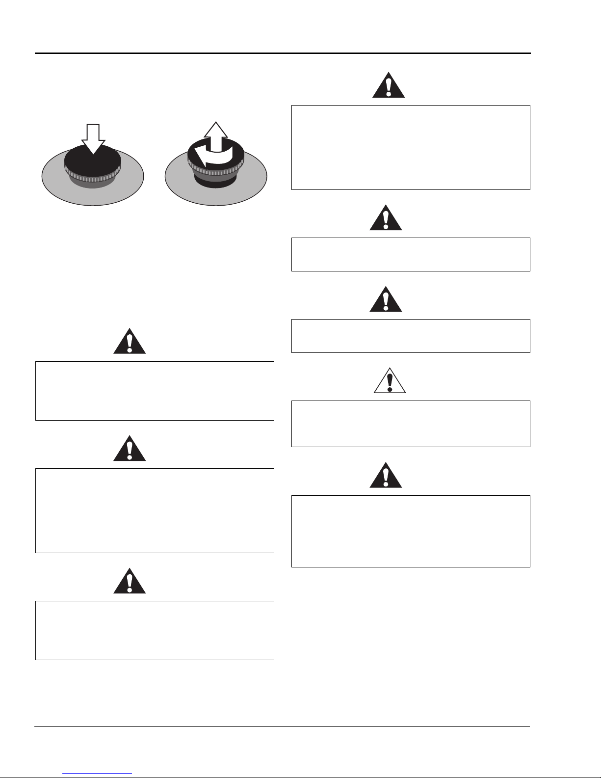
Push either
button to stop the
laminator
A
U
S
NOT
E
C
N
E
G
R
U
'
D
T
E
R
T
OP
R
A
E
M
E
R
G
E
N
C
Y
S
Twist and pull up
both buttons to
resume operation
1
NOT
/
4
E
C
N
E
G
R
U
'
D
T
E
R
R
Figur e 1-1: Us ing the Emergency Stop Buttons
ALWAYS CHECK THE INFRARED SENSORS
PRIOR TO OPERATION! The sensors must be
clean and have free view of the roll to maintain
A
U
S
E
n
r
u
t
M
E
R
G
E
N
C
Y
S
T
OP
A
proper r oll oper ating temperatur es. T he r olls can
overheat and cause a fir e or seriou sly damage the
laminator.
Despite the safety featur es built into the Falcon 40
Laminator, extreme caution must be used when operating or servicing the unit. READ THE FOLLOWING
WARNINGS AND CAUTIONS BEFORE YOU
ATTEMPT TO OPERATE OR SERVICE THE
FALCON 40 LAMINAT OR.
Never place fingers or arms between the rolls
when they are turning or when the rolls are in
the closed position . You can be crushed or
burned.
Secure long hair so that it cannot get caught in
the machinery. Do not wear ties, loose fitting
clothing or dangling jewelry while operating or
servicing the laminator. These items can get
caught in the nip, and you can be choked,
crushed, or burned.
Always use care in lowering the top laminating
roll. Yo u ca n be cr us he d or burn ed .
Do not operate the laminator ne ar water. You can
be severely shocked, electrocuted or cause a fire.
Unplug the laminat or from the wall ou tlet before
servicing. You can be severely shocked,
electrocuted or cause a fire.
Do not use liquid or aerosol cleaners on the
laminator. Do not spill liquid of any kind on the
laminator. You can be severely shocked,
electroc uted or cause a fire. Use only a damp
cloth for cleaning the cabinet.
Use extreme caution when operating the
laminator with the foots wit ch. The photoelectric
eye system is overridden and your fingers can get
caught in the nip. You can be crushed or burned.
Page 7

F-40 Laminator Operator Manual
Safety
© GBC Pro-Tech 1998 February
1-3
WARNING
CAUTION
CAUTION
CAUTION
CAUTION
WARNING
CAUTION
WARNING
Exercise care when cleaning the rolls with 80%
isopropyl alc ohol:
• Use only in a well ventilated area.
• Wear rubber gloves.
• Use only on cool rolls.
Cleaning hea te d rolls ca n ign i te the fum es.
Use only 80% isopropyl alcohol or a rubber
cement eraser to clean the laminating rolls.
Harsh chemicals like toluene, acetone or MEK
destroy the silic one covering of the rolls.
Raise the upper main roll when the laminator is
not in operation. Prolonge d contact can damage
the rolls.
Excess pressure can damage the laminating rolls.
Always select the minimum roll pressure
necessary to complete the task.
If silicone adhesive contacts the upper or lower
roll, remove it IMMEDIATELY using 80%
isopropyl alc ohol. It can harden within an hour
and ruin the roll.
The operating environ ment must be free of dust,
flammable liquids and vapors. You can be
injured by inhaling chemical vapors. Vapor build
up or stored flammable liquids can cause a fire.
Excessive dust can damage the laminator.
Do not use a kni fe or ot her sharp instrum ent
during installation or while servic ing the
laminator. You can cause irrepara ble damage to
the rolls.
Do not attempt to move the laminator across
anything other than a f lat, level surface wit hout
trained and qualified riggers. You can be crushed
or seriously injured.
The Falcon 40 Laminator is a large and heavy
piece of equipment. It is necessary to employ
LICENSED RIGGERS ONL Y to move the
machine. The laminator is not designed to be
tipped up or sideways in any way . Suc h actio n
disturbs the exact alignment of the rolling parts
of the machine and requires extensive
realignment . G BC Pro-Tech’s war ranty does not
cover malfunction of the equipment due to
mishandling and/or tipping.
GBC Pro-Tech bears no responsibility for
personal injury or damage due to moving the
laminator improp erly.
Page 8

Safety
F-40 Laminator Operator Manual
1-4
© GBC Pro-Tech 1998 February
WARNING
WARNING
WARNING
WARNING
WARNING
WARNING
WARNING
Connect the laminator only to the type of power
source indicat ed o n the label o n the back of the
laminato r. You can be severel y shocked,
electrocuted or cause a fire. If you are not sure of
the type of power available consult the dealer or
local power company.
Do not attempt to defeat the grounding feature of
the ground plug on the laminator. You can be
severely shock ed , ele ctrocu ted or cause a fire.
The three prong plu g fits on ly into a grou nding-
type power outlet. If you are unable to insert the
plug into th e existi n g outlet, contac t a qua lified
electricia n to replace the obsolete o utlet.
Do not attempt to plug any device into the
vacuum table outlet that does not require 240V.
You can be severely shocked, electrocuted or
cause a fire.
Never ins ert obj ect s of an y kin d thro ugh a ny of
the slots on the laminator. You can touch
dangerous volta g e poi nt s or sh o rt out pa rts . You
can be severely shocked, electrocuted or cause a
fire.
ALWAYS USE GOOD SAFETY PRACTICES
WHEN OPERATING OR SERVICING THE LAMINATOR AND KNOW HOW TO REACT QUICKLY
IN AN EMERGENCY.
&DXWLRQ:DUQLQJ /DEHO /RFDWLRQV
Do not use an extension cord on this laminator.
Yo u can be s ev erely shock ed , el ect rocu ted or
cause a fire. If you need a longer cable contact a
qualified electrician.
Do not operate t he laminator if the powe r cord is
damaged or fr ayed. You can be severel y shocked,
electrocut ed o r caus e a fire. Contact a qualified
electrician to replace the cord.
Do not allow anything to rest on the power cord.
Do not locate the co rd where people can walk on
it. Yo u o r others can be severely sh ocked,
electrocuted or cause a fire.
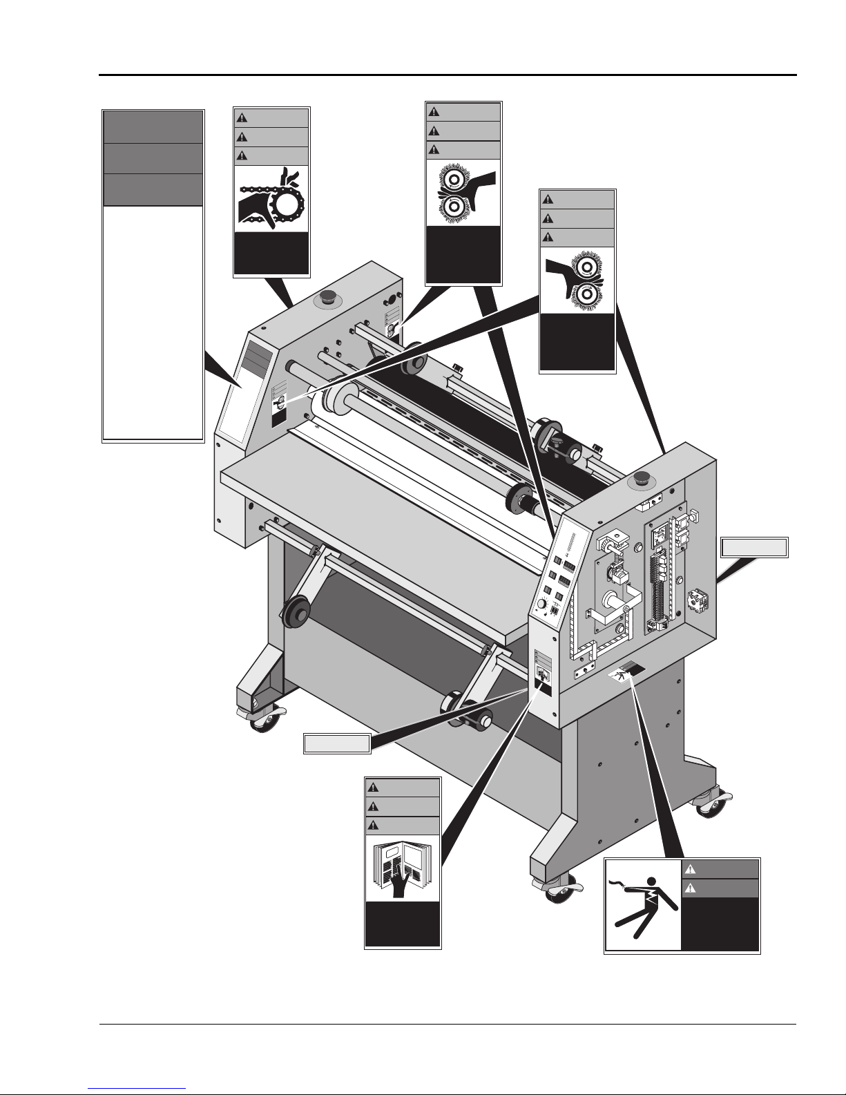
Posted at various locations on your Falcon 40 Laminator are import ant sa fety label s. PAY CAREFUL
ATTENTION TO THESE LABELS AT ALL TIMES!
Figure 1-2 shows the location of each of these
labels.
Page 9
F-40 Laminator Operator Manual
Safety
© GBC Pro-Tech 1998 February
1-5
SAFETY
SAFETY
INSTRUCTIONS
INSTRUCTIONS
SICHERHEITS-
SICHERHEITS-
RICHTLINIEN
RICHTLINIEN
CONSIGNES DE
CONSIGNES DE
SÉCURITÉ
SÉCURITÉ
1. Read and understand the Operation
1. Read and understand the Operation
Manual and all safety labels before
Manual and all safety labels before
operating this machine.
operating this machine.
2. Only a trained person is to be
2. Only a trained person is to be
permitted to operate this machine.
permitted to operate this machine.
Training should include instruction
Training should include instruction
in operation under normal conditions
in operation under normal conditions
and emergency situations.
and emergency situations.
3. This machine is to be serviced only
3. This machine is to be serviced only
by trained and authorized personnel.
by trained and authorized personnel.
Follow lockout procedures before
Follow lockout procedures before
servicing.
servicing.
4. Never reach into the machine for any
4. Never reach into the machine for any
reason unless the machine is at a
reason unless the machine is at a
COMPLETE STOP.
COMPLETE STOP.
5. Never leave the machine stopped in
5. Never leave the machine stopped in
such a manner that another worker can
such a manner that another worker can
start the machine while you are working
start the machine while you are working
on or within the machine.
on or within the machine.
6. Never change or defeat the function of
6. Never change or defeat the function of
electrical interlocks or other machine
electrical interlocks or other machine
“shutdown” switches.
“shutdown” switches.
7. Before starting this machine, check that:
7. Before starting this machine, check that:
- All persons are clear of the machine.
- All persons are clear of the machine.
- No maintenance work is being performed
- No maintenance work is being performed
on the machine.
on the machine.
- All guards are in place.
- All guards are in place.
- All parent rolls are well chucked in the
- All parent rolls are well chucked in the
unwind stands.
unwind stands.
- The machine is free of paper scraps,
- The machine is free of paper scraps,
wraps and jams.
wraps and jams.
8. There is a potential hazard of entanglement
8. There is a potential hazard of entanglement
in this machine caused by items such as
in this machine caused by items such as
long hair, loose clothing and jewelry.
long hair, loose clothing and jewelry.
Make sure your clothing and hair fit
Make sure your clothing and hair fit
closely to your body and that all jewelry,
closely to your body and that all jewelry,
rings and watches are removed.
rings and watches are removed.
©1994 HCS, Inc. 800-748-0241 Reorder No.7002-PT
©1994 HCS, Inc. 800-748-0241 Reorder No.7002-PT
WARNING
WARNING
ACHTUNG
ACHTUNG
MISE EN GARDE
MISE EN GARDE
Moving parts can
Moving parts can
crush and cut.
crush and cut.
Do not operate with
Do not operate with
door open.
door open.
©1994 HCS, Inc. 800-748-0241 Reorder No. 1012-PT
©1994 HCS, Inc. 800-748-0241 Reorder No. 1012-PT
SAFETY
SAFETY
INSTRUCTIONS
INSTRUCTIONS
SICHERHEITS-
SICHERHEITS-
RICHTLINIEN
RICHTLINIEN
CONSIGNES DE
CONSIGNES DE
SÉCURITÉ
SÉCURITÉ
1.Read and understand the Operation
1.Read and understand the Operation
Manual and all safety labels before
Manual and all safety labels before
operating this machine.
operating this machine.
2.Only a trained person is to be
2.Only a trained person is to be
permitted to operate this machine.
permitted to operate this machine.
Training should include instruction
Training should include instruction
in operation under normal conditions
in operation under normal conditions
and emergency situations.
and emergency situations.
3.This machine is to be serviced only
3.This machine is to be serviced only
by trained and authorized personnel.
by trained and authorized personnel.
Follow lockout procedures before
Follow lockout procedures before
servicing.
servicing.
4.Never reach into the machine for any
4.Never reach into the machine for any
reason unless the machine is at a
reason unless the machine is at a
COMPLETE STOP.
COMPLETE STOP.
5.Never leave the machine stopped in
5.Never leave the machine stopped in
such a manner that another worker can
such a manner that another worker can
start the machine while you are working
start the machine while you are working
on or within the machine.
on or within the machine.
6.Never change or defeat the function of
6.Never change or defeat the function of
electrical interlocks or other machine
electrical interlocks or other machine
“shutdown” switches.
“shutdown” switches.
7.Before starting this machine, check that:
7.Before starting this machine, check that:
- All persons are clear of the machine.
- All persons are clear of the machine.
- No maintenance work is being performed
- No maintenance work is being performed
on the machine.
on the machine.
- All guards are in place.
- All guards are in place.
- All parent rolls are well chucked in the
- All parent rolls are well chucked in the
unwind stands.
unwind stands.
- The machine is free of paper scraps,
- The machine is free of paper scraps,
wraps and jams.
wraps and jams.
8.There is a potential hazard of entanglement
8.There is a potential hazard of entanglement
in this machine caused by items such as
in this machine caused by items such as
long hair, loose clothing and jewelry.
long hair, loose clothing and jewelry.
Make sure your clothing and hair fit
Make sure your clothing and hair fit
closely to your body and that all jewelry,
closely to your body and that all jewelry,
rings and watches are removed.
rings and watches are removed.
©1994 HCS, Inc. 800-748-0241 Reorder No.7002-PT
©1994 HCS, Inc. 800-748-0241 Reorder No.7002-PT
Crush and burn
Crush and burn
hazard. Stay clear
hazard. Stay clear
of moving rollers.
of moving rollers.
Stop machine and
Stop machine and
raise roll before
raise roll before
cleaning.
cleaning.
4
9
9
1
©1994 HCS, Inc. 800-748-0241
©
WARNING
WARNING
ACHTUNG
ACHTUNG
MISE EN GARDE
MISE EN GARDE
WARNING
WARNING
ACHTUNG
Crush and burn
Crush and burn
hazard. Stay clear
hazard. Stay clear
of moving rollers.
of moving rollers.
Stop machine and
Stop machine and
raise roll before
raise roll before
cleaning.
cleaning.
©1994 HCS, Inc. 800-748-0241 Reorder No.1033R-PT
WARNING
WARNING
ACHTUNG
ACHTUNG
MISE EN GARDE
MISE EN GARDE
Crush and burn
Crush and burn
hazard. Stay clear
hazard. Stay clear
of moving rollers.
of moving rollers.
Stop machine and
Stop machine and
raise roll before
raise roll before
cleaning.
cleaning.
0
0
0
0
. 8
c
. 8
c
, In
S
, In
C
S
C
H
4
H
9
4
9
9
1
9
©
1
©
T
T
-P
R
-P
3
R
3
3
0
3
.1
0
o
.1
o
N
r
N
e
r
e
rd
d
o
r
e
o
R
e
R
1
4
1
2
4
0
2
-
8
-0
4
8
4
-7
7
-
©1994 HCS, Inc. 800-748-0241 Reorder No.1033R-PT
A
R
R
A
R
OP
E
R
OP
E
T
T
T
T
S
D
S
D
Y
'
Y
U
'
C
U
C
R
R
N
N
G
E
G
E
E
G
E
G
N
N
R
R
C
E
C
E
E
M
E
M
E
E
NOT
S
U
NOT
A
S
U
A
WARNING
WARNING
ACHTUNG
ACHTUNG
MISE EN GARDE
MISE EN GARDE
T
-P
3
3
0
.1
o
r N
e
rd
o
e
Reorder No.1033-PT
R
1
4
2
-0
8
4
-7
0
0
. 8
c
, In
S
C
H
ACHTUNG
MISE EN GARDE
MISE EN GARDE
Crush and burn
Crush and burn
hazard. Stay clear
hazard. Stay clear
of moving rollers.
of moving rollers.
Stop machine and
Stop machine and
raise roll before
raise roll before
cleaning.
cleaning.
©1994 HCS, Inc. 800-748-0241 Reorder No.1033-PT
©1994 HCS, Inc. 800-748-0241 Reorder No.1033-PT
A
A
R
R
R
R
OP
OP
E
E
T
T
T
T
S
S
D
D
Y
Y
'
'
U
U
C
C
R
R
N
N
G
G
E
E
E
E
G
G
N
N
R
R
C
C
E
E
E
E
M
M
E
E
NOT
NOT
S
S
U
U
A
A
240 VOL TS
240 VOL TS
LEM PRODUCTIONS, INC. DOYLESTOWN PA LVM-240C
LEM PRODUCTIONS, INC. DOYLESTOWN PA LVM-240C
WARNING
WARNING
ACHTUNG
ACHTUNG
MISE EN GARDE
MISE EN GARDE
Carefully read Operator's
Carefully read Operator's
Manual before handling
Manual before handling
this machine. Observe
this machine. Observe
instructions and safety
instructions and safety
rules when operating.
rules when operating.
©1994 HCS, Inc. 800-748-0241 Reorder No.6001-PT
©1994 HCS, Inc. 800-748-0241 Reorder No.6001-PT
REV
FANS
1
O
1
T
O
O
100
P
75
50
PROTECH
1
8
6
10
4
B
12
O
O
2
UT
O
150
T
48
175
125
0
T
100
16
O
75
18
M
PRO-TECH Engineering Madison,WI 608-246-8844
50
PROTECH
275
°F
300
001-133
LO
WARNING
WARNING
ACHTUNG
ACHTUNG
MISE EN GARDE
MISE EN GARDE
Carefully read Operator's
Carefully read Operator's
Manual before handling
Manual before handling
this machine. Observe
this machine. Observe
instructions and safety
instructions and safety
rules when operating.
rules when operating.
©1994 HCS, Inc. 800-748-0241 Reorder No.6001-PT
©1994 HCS, Inc. 800-748-0241 Reorder No.6001-PT
A+A-
A+A-
CL
CL
L1L2
psi
MOTOR
FWD
100
kPa
90
700
80
630
70
560
6
9
60
490
50
420
AUTO
40
12
350
3
30
280
20
210
10
140
15
0
70
SPEED
18
STOP
POWER
HEATERS
O
UT
150
175
125
200
HI
225
250
275
°F
300
001-133
LO
200
HI
225
250
DANGER
DANGER
ic
n
u
m
m
o
C
d
r
a
z
a
H
4
9
9
©1994 Hazard Communication Systems, Inc. 800-748-0241 Reorder No. 5025-PT
1
©
©1994 Hazard Communication Systems, Inc. 800-748-0241 Reorder No. 5025-PT
©1994 Hazard Communication Systems, Inc. 800-748-0241 Reorder No. 5025-PT
L1L2
FUSE
FUSE
F-
F-
ARM
ARM
I1
I1
P2P1I1 F+
P2P1I1 F+
MIN IR
MIN IR
P3
P3
FUSE
FUSE
ACCEL
ACCEL
LINE
LINE
MAX
MAX
P/N 9884
P/N 9884
KBIC BARRIER TERMINAL BOARD
KBIC BARRIER TERMINAL BOARD
S
U
O
GEFAHR
D
GEFAHR
E.
T
R
-P
5
2
G
0
. 5
o
ZA
N
r
e
d
r
A
o
LTA
e
R
H
HAZARDOUS
O
V
VOLTAGE.
To be serviced only
To be serviced only
by trained and
by trained and
authorized personnel.
authorized personnel.
Lockout power before
Lockout power before
servicing.
servicing.
1
4
2
-0
8
4
-7
0
0
. 8
c
, In
s
m
te
s
y
S
n
tio
a
240 VOL TS
240 VOL TS
LEM PRODUCTIONS, INC. DOYLESTOWN PA LVM-240C
LEM PRODUCTIONS, INC. DOYLESTOWN PA LVM-240C
DANGER
DANGER
GEFAHR
GEFAHR
HAZARDOUS
HAZARDOUS
VOLTAGE.
VOLTAGE.
To be serviced only
To be serviced only
by trained and
by trained and
authorized personnel.
authorized personnel.
Lockout power before
Lockout power before
servicing.
servicing.
Figur e 1-2: Locations of Safety Labels
Page 10

Safety
F-40 Laminator Operator Manual
1-6
© GBC Pro-Tech 1998 February
Blank page.
Page 11

F-40 Laminator Operator Manual
Installation
© GBC Pro-Tech 1998 February
2-1
6HFWLRQ ,QVWDOODWLRQ
CAUTION
WARNING
CAUTION
CAUTION
Before a Falcon 40 Lamin ator can be i nstalled the re are
a few requir ements that must be met. Make certain that
each of the requirements listed in the following preinstallation checklist are met before beginning installation.
Failure t o follow the preinst allation checklist c an
result in damage to the laminator.
3UHLQVWDOODWLRQ &KHFNOLVW
❏ Are doorways and hall ways wide enough for the
laminator to be moved to the installation site?
❏ Is there ample room for the laminator?
A work area must be established that allows for
operation in both the front and the rear of the
machine and provides space for efficient material
flow. Figure 2-1 shows a typical machine area layout.
❏ Is there an appropriate power outlet available or
has a certified electrician been contacted to wire
the laminator directly?
The laminator requires 30A single phase service
and a power receptacle that accepts a 30A 250V
NEMA L6-30P plug or, in Europe, 3 phase, 240/
400 VAC with 20A per phase. See Figure 2-6 for
power cord connection options.
Position the jumpers as shown in Figure 2-6 for
service cho ice.
❏ Is the environ ment appropriate for the laminator?
The laminator r equires a clean, dust and vapor free
environment to operate properly. It must not be
located where there is air blowing directly on the
machine.
The operating environment must be free of dust,
flammable liquids and vapors. You can be
injured by inhali ng chemical vapors. Vapor build
up or stored flammable liqui ds can cause a fire .
Excessive dust can damage the laminator.
Do not locate the laminator where air is blowing
directly on the machine. The air flow can cool
the rolls unevenly and r esult in poor quality
output.
Page 12

Installation
F-40 Laminator Operator Manual
2-2
© GBC Pro-Tech 1998 February
Recommended
clearance
73" (~1.8m)
Floor Trimmer
10'
(~3m)
4'6" (~1.1m)
3' (~1m)
Table
3' x 6' (~1m x 2m)
2'2"
(~.7m)
10'
(~3m)
Figure 2-1: Laminator Space Requirements
Page 13

F-40 Laminator Operator Manual
Installation
© GBC Pro-Tech 1998 February
2-3
8QSDFNLQJ
NOTE
WARNING
CAUTION
☞
ALL SHIPMENTS ARE EX- WORKS. At our dock, title
passes to the buyer. Please review your insurance coverage prior to shipment, as you are responsible for all
subsequent freight charges and risks. Before signing
the Bill of Lading, be sure to inspect the crate and/or
pallet for signs of damage or missing items ; if applicable, make a note of this on the Bill of Lading.
The Falcon 40 Laminator is shipped one of two ways.
It is either encased in a plywood crate on a skid or in a
cardboard box on a skid.
The unpacking process requires at least two
people. You can be severel y inj ured o r cru sh ed .
Tools required:
• Phillips head screwdrive r
7
•
/8" open end wrench or adjustable wrench
If the laminator is in a cardboard box:
1. Remove the securing screws around the bottom of
the box using the Phillips head screwdriver as
shown in Figure 2-2.
Figure 2-2: Re moving the Cardboard Box
2. Lift the cardb oard box off the laminator .
3. Gently unwrap the shr ink wrap from around the
laminator.
Do not use a kni fe or ot her sharp instrum ent
during installation or while servic ing the
laminator. You can cause irrepara ble damage to
the rolls.
4. Carefull y remove any accessories packed with the
laminator. The accessory pack should contain:
1 Set, hex wrench e s
1 Slitting knife
1 Manual
1 Set, spare fuses
1 T ape measure
1 Roll of masking tape
1 Rubber ce ment eras e r
Page 14

Installation
F-40 Laminator Operator Manual
2-4
© GBC Pro-Tech 1998 February
WARNING
CAUTION
A NOTE ABOUT RECYCLING
NOTE
Foot Bolt
Shipping
Pad
Figure 2-3: The Foot Bolts
5. Remove the screws holding the foot pads onto the
pallet using the Phill ips head screwdriver.
6. Have the l aminator li f ted of f the ski d and pl aced on
the floor by licensed riggers. The r iggers must also
unscrew the foot bolts from the laminator frame
since it requires lifting the laminator.
Do not attempt to move the laminator across
anything other th an a flat, level surface without
trained and qualified riggers. You can be crushed
or seriously injur ed.
Do not use a kni fe or ot her sharp instrum ent
during installation or while servic ing the
laminator. You can cause irrepara ble damage to
the rolls.
9. Remove all packing materials to a safe distance
fro m the lamina to r.
☞
The pallet can be reused for shipping the machine
again, or can be disassembled and the wood and
screws recycled. The cardboard can be recycled. The
shrink wrap is not recyclable, however, so it must be
discarded.
☞
A word about international shipments: As these are
heavy pieces of equipment, GBC Pro-Tech takes every
precaution to ensure that our laminators are properly
crated to the highest standards.
Before machines leave our loading dock, they are pre treated with a VCI protective film to provide total corrosion protection. This protective film is wrapped
around the machine and compl etely seale d. In addition ,
moisture absorbing silicone desiccite packs are packed
inside the crate and machine cabinets.
The Falcon 40 Laminator is a large and heavy
piece of equipment. It is necessary to employ
LICENSED RIGGERS ONLY to move the
machine. The laminator is not designed to be
tipped up or sideways in any way. Such action
disturbs the exact alignment of the rolling parts
of the machin e and requires extensive
realignment. GBC Pro-Tech’s warranty does not
cover malfun cti o n of the equipment du e to
mishandling and/or tipping.
GBC Pro-Tech bears no responsibility for
personal injury or damage due to moving the
laminator improperly.
7. Once the lamin ator is in place set the locking
mechanism on all four wheels to ON.
8. Remove any plastic strapping and packing paper
taped to the
roll
s.
Prior to start up of the machine, you must rem ove the
desiccite packs from each cabinet and discard. DO
NOT operate the machine with the desiccite packs
inside the cabinets.
Page 15
F-40 Laminator Operator Manual
Installation
© GBC Pro-Tech 1998 February
2-5
If the laminator is in a crate:
CAUTION
CAUTION
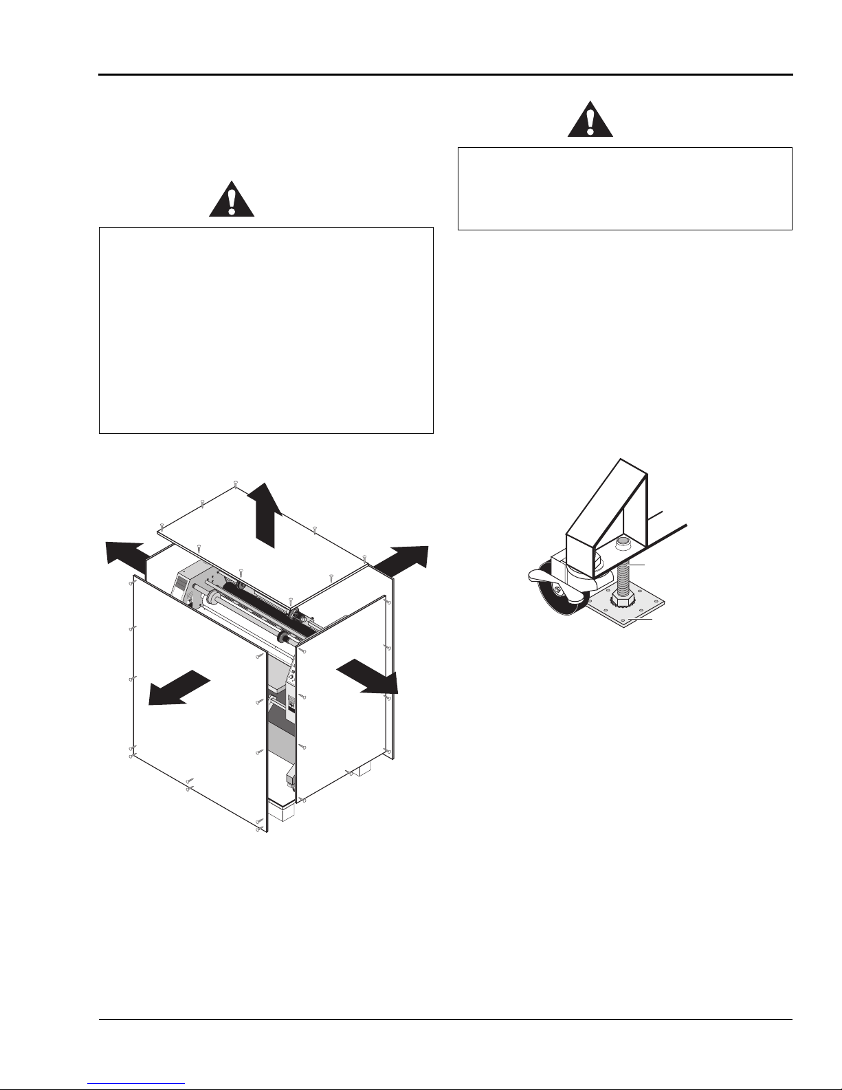
1. Remove the top of the crate and then the sides in
the order shown in Figure 2-4.
Do not use a kni fe or ot her sharp instrum ent
during installation or while servic ing the
laminator. You can cause irrepara ble damage to
the rolls.
Do not allow the top to fall into the crate. It can
damage the laminator.
Do not put packing screws on the floor. They can
cause problems when trying to roll the machine
into position.
A second person must support the side labeled 5
in Figure 2-4. It can fall and damage the
laminator.
1
A
R
R
OP
E
T
T
S
D
Y
'
U
C
R
N
G
E
E
G
N
R
C
E
E
M
E
NOT
S
U
4
3
A
WARNING
ACHTUNG
MISE EN GARDE
rn
r
u
a
b
le
d
c
.
n
y
a
rs
ta
h
lle
s
d
. S
n
ru
ro
a
rd
C
g
e
a
z
in
in
a
v
h
re
h
SAFETY
INSTRUCTIONS
SICHERHEITSRICHTLINIEN
CONSIGNES DE
SÉCURITÉ
1.Read and understand the Operation
Manual and all safety labels before
operating this machine.
2.Only a trained person is to be
permitted to operate this machine.
Training should include instruction
in operation under normal conditions
and emergency situations.
3.This machine is to be serviced only
by trained and authorized personnel.
Follow lockout procedures before
servicing.
WARNING
4.Never reach into the machine for any
reason unless the machine is at a
ACHTUNG
COMPLETE STOP.
5.Never leave the machine stopped in
MISE EN GARDE
such a manner that another worker can
start the machine while you are working
on or within the machine.
6.Never change or defeat the function of
electrical interlocks or other machine
“shutdown” switches.
7.Before starting this machine, check that:
- All persons are clear of the machine.
- No maintenance work is being performed
on the machine.
- All guards are in place.
- All parent rolls are well chucked in the
Crush and burn
unwind stands.
- The machine is free of paper scraps,
hazard. Stay clear
wraps and jams.
of moving rollers.
1
.
o
N
r
e
d
r
o
8.There is a potential hazard of entanglement
e
Stop machine and
R
raise roll before
in this machine caused by items such as
1
4
2
0
-
8
long hair, loose clothing and jewelry.
4
cleaning.
7
-
0
0
8
.
c
n
I
,
Make sure your clothing and hair fit
S
C
H
4
9
9
1
©
closely to your body and that all jewelry,
rings and watches are removed.
©
1
9
9
4
H
C
S
, In
c
. 8
0
0
-
7
4
8
-
0
2
4
1
R
e
o
r
d
e
r
N
o
.
7
0
0
2
-
P
T
o
c
fo
a
e
f m
T
P
-
m
o
R
3
3
p
0
ll b
1
.
o
N
r
to
e
d
r
ro
o
S
e
.
R
e
g
is
in
ra
n
a
1
4
2
0
le
-
8
4
c
7
-
0
0
8
.
c
n
I
,
S
C
H
4
9
9
1
©
T
P
3
3
0
A
R
R
OP
E
T
T
S
D
Y
'
U
C
R
N
G
E
E
G
N
R
C
E
E
M
E
NOT
S
U
A
psi
100
kPa
90
700
80
630
70
560
60
490
50
420
40
350
30
280
20
210
10
140
70
8
6
1
0
4
1
2
2
4
8
0
1
6
1
8
W
A
R
N
A
IN
C
G
H
TU
MISE EN GARDE
N
G
Carefully read Operator's
Manual before handling
this machine. Observe
instructions and safety
rules when operating.
DANGER
©
1
9
9
4
H
C
S
,
I
n
c
.
8
0
0
7
4
8
0
2
4
1
GEFAHR
R
e
o
r
d
e
r
N
o
.
6
0
0
1
P
T
HAZARDOUS
VOLTAGE.
T
P
-
5
2
0
5
.
o
N
r
e
To be serviced only
d
r
o
e
R
by trained and
authorized personnel.
Lockout power before
servicing.
1
4
2
0
-
8
4
7
-
0
0
8
.
c
n
I
,
s
m
e
t
s
y
S
n
o
i
t
a
c
i
n
u
m
m
o
C
d
r
a
z
a
H
4
9
9
1
©
5
2
3. Carefull y remove any accessories packed with the
laminator. The accessory pack should contain:
1 Set, hex wrench e s
1 Slitting knife
1 Manual
1 Set, spare fuses
1 T ape measure
1 Roll of masking tape
1 Rubber ce ment eras e r
Foot Bolt
Shipping
Pad
Figure 2-5: The Foot Bolts
4. Remove the screws holding the foot pads onto the
pallet using the Phillips head screwdriver.
5. Have the laminator lifte d off the skid and placed on
the floor by lic ensed riggers. The riggers must also
unscrew the foot bolts from the laminator frame
since it requires lifting the laminator.
Figur e 2-4: R emov ing the Crate
2. Gently unwrap the shrink wrap from around the
laminator.
Page 16

Installation
F-40 Laminator Operator Manual
2-6
© GBC Pro-Tech 1998 February
WARNING
CAUTION
A NOTE ABOUT RECYCLING
NOTE
Do not attempt to move the laminator across
anything other th an a flat, level surface without
trained and qualified riggers. You can be crushed
or seriously injur ed.
The Falcon 40 Laminator is a large and heavy
piece of equipment. It is necessary to employ
LICENSED RIGGERS ONLY to move the
machine. The laminator is not designed to be
tipped up or sideways in any way. Such action
disturbs the exact alignment of the rolling parts
of the machin e and requires extensive
realignment. GBC Pro-Tech’s warranty does not
cover malfun cti o n of the equipment du e to
mishandling and/or tipping.
GBC Pro-Tech bears no responsibility for
personal injury or damage due to moving the
laminator improperly.
☞
A word about international shipments: As these are
heavy pieces of equipment, GBC Pro-Tech takes every
precaution to ensure that our laminators are properly
crated to the highest standards.
Before machines leave our loading dock, they are pre treated with a VCI protective film to provide total corrosion protection. This protective film is wrapped
around the machine and compl etely seale d. In addition ,
moisture absorbing silicone desiccite packs are packed
inside the crate and machine cabinets.
Prior to start up of the machine, you must rem ove the
desiccite packs from each cabinet and discard. DO
NOT operate the machine with the desiccite packs
inside the cabinets.
6HWXS
Once the Falcon 40 Laminator has been unpacked and
moved into final position check each of the foll owing
items.
6. Once the lamin ator is in place set the locking
mechanism on all four wheels to ON.
7. Remove any plastic strapping and packing paper
taped to the
Do not use a knife or other sharp instrument
during installation or while servicing the
laminator. You can cause irreparable damage to
8. Remove all packing materials to a safe distance
from the laminator.
☞
The crate components can be reused for shipping the
machine again, or can be disassembled and the wood
and scre ws recycled. The shrink wrap is not re cyc lable,
however, so it must be discarded.
roll
s.
the rolls.
T ools required:
1
•
/8" hex wrench
• Adjustable wrench
Setup Proce du re
1. Inspect the la minator for any obvious shipping
damage.
2. Remove the drive and control side cabinet covers
1
with the
screws holding each cover in place.
3. Inspect all the bolts and tighten any that were loosened during shipping.
4. Check the upp er ma in
handwheel to raise and lower the
move smoothly.
5. Set the nip. (See Section 4: Maintenance and Trou-
bleshooting for the procedur e.)
6. Verify that both inf rare d sensors are clean and have
an uninterrupted view of the rolls.
/8" hex wrench by removing the six
assembly by using the
roll
. It should
roll
Page 17

F-40 Laminator Operator Manual
Installation
© GBC Pro-Tech 1998 February
2-7
WARNING
ALWAYS CHECK THE INFRARED SENSORS
L1-3
L2-3
N3
L3-3
L1-4
L2-4
N6N4N5
L3-4
L2-2
N7
N2
Blue
L1L2L3
N
Line-1
Line-2
Line-3
PE
GND
Cabinet
Stud
L1-3
L2-3
L3-3
The United States
3-Phase Delta
NU
N
L2
L1
L3
The European
3-Phase Y
L1-3
L2-3
N3
L3-3
L1-4
L2-4
N6N4N5
L3-4
L2-2
N7
N2
Blue
L1L2L3
N
Line-1
Line-2
Line-3
GND
Cabinet
Stud
Jumpers Relocate
As Shown For
Selected Service
L1-3
L2-3
N3
L3-3
L1-4
L2-4
N6N4N5
L3-4
L2-2
N7
N2
Blue
L1L2L3
N
Line-1
Line-2
GND
Cabinet
Stud
Single Phase (U.S.)
PRIOR TO OPERAT ION! The sensors must be
clean and ha ve free v ie w of the roll to maintain
proper r oll operatin g te mperatures. The rolls can
overheat and cause a fire or seriously damage
the laminator.
7. Plug the laminator into an approved socket or ha ve
a certifie d electrician wire the laminator directly to
a power source.
The laminator requires 30A single phase service
and a power receptacle that accepts a 30A 250V
NEMA L6-30P plug or, in Europe, 3 phase, 240/
400 VAC with 20A per phase. See Figure 2-6 for
power cord connection options.
8. Verify that the photoelectric eye is working properly. (See the procedure below.)
9. Replace both cabinet covers.
Figure 2-6: Pow er Cord Connection
Page 18

Installation
F-40 Laminator Operator Manual
2-8
© GBC Pro-Tech 1998 February
6WDUWXS
WARNING
WARNING
The first time the laminator is started and every time it
is serviced you should use the following checklist to
confirm that the unit is operating properly and that all
safety mechanisms are functioning.
Startup Checklist
Start the laminator and go through the foll owing checklist.
❏ Are the emergency stop buttons working?
Push down on one of the emergency stop buttons.
The laminator should stop. Pull up on the button.
The laminator should resume opera tion. Always
check both buttons.
Never operate the laminator unless both of the
emergency stop buttons are fun ction ing
properly. You can be crushed or burn ed.
operation. Verify that the footswitch overri des the
photoelectric eye by pressing the footswitch and
pushing an object as lar ge as your hand into the nip
area.
Once you have com pleted the startup checklist you can
safely run a test sample.
❏ Is the photoelectric eye system working?
With the laminator running, place an object
approximately the size of your hand just in front of
the nip to co nfirm that the photo elec tric e ye syste m
is functioning. The
object away from the nip. The laminator should
resume operation.
Never operate the laminator unless the
photoelectric eye system is functioning properly.
You can be crushed or burned.
❏ Is the motor functi oning?
Test the motor at various speeds ranging from
0-18. At 0 the
Run the motor in both forward and reverse.
❏ Are the heaters wor king?
Verify that the top heater controller heats the top
roll and the bottom heater controller heats the bottom roll.
roll
s should stop. Move the
roll
s should stop turning.
❏ Is the footswitch operating?
Test the footswitch for both forward and reverse
Page 19

F-40 Laminator Operator Manual
Operation
© GBC Pro-Tech 1998 February
3-1
6HFWLRQ 2SHUDWLRQ
WARNING
NOT
A
U
S
E
M
E
R
G
E
N
C
Y
S
T
OP
A
R
R
E
T
D
'
U
R
G
E
N
C
E
NOT
A
U
S
E
M
E
R
G
E
N
C
Y
S
T
OP
A
R
R
E
T
D
'
U
R
G
E
N
C
E
Twist and pull up
both buttons to
resume operation
Push either
button to stop the
laminator
1
/
4
t
u
r
n
6DIHW\
GBC Pro-Tech laminators are powerful machines that
are designed to mount, laminate and encapsulate. The
forces required to accom plish these tasks can vary fr om
negligible to very lar ge.
The spring system used to provide downward pr ess ure
on the top roll is capable of producing f orce s greater
than 1000 pounds (454kg ). This force is applied to any
object presented in the opening (called the nip)
between the two rolls.
In addition, the laminating rolls of the Falcon 40 can
reach temperatures of over 200°F (100°C). At these
temperatures there is a danger of a severe burn if the
rolls are touch ed during set-up, operation or servicing.
An important feature of the laminator is the photoelectric eye system that stops the machine when objects
move into the nip area. Once the blocking objec t is
removed and the light beam reestablished, the rolls
resume turning. However, this system is overridden if
you use the footswitch.
Figure 3-1: Using the Emergency Stop Buttons
Despite the safety features built into the Falcon 40
Laminator , e xtreme caution must be used when operating or servicing the unit.
Reset Button
Disconnect
laminator with the footswitch. The photoelectric
The Falcon 40 Laminator has a steel cabinet that is
bolted closed to isolat e the elec trical and drive system
components for the safety of the operator. Only a qualified service techni ci an should open these cabinets.
The laminator is equipped with two emergency stop
buttons located on the top of eith er side of the laminator. Either of these, if engaged, stops the lamina tor. To
continue operation both e mergency stop buttons must
be in the up position and you must press the reset button above the fuse panel on the back of the laminator.
Use extreme caution when operating the
eye system is overridden, and your fingers can
get caught in the nip. You can be crushed or
burned.
GBC PRO-TECH ENGINEERING, INC.
DE FOREST, W
Model No. Serial No.
ISCONSIN
VAC
Hz
Amps
Phase
Wires
M
AD
E IN
U.S.A.
Figure 3-2: Re s et Button
Page 20

Operation
F-40 Laminator Operator Manual
3-2
© GBC Pro-Tech 1998 February
2SHUDWRU &RQWUROV
The operator controls fo r the Falc on 40 Laminator are
located on the front of the unit, to the right of the operator position. The names and funct ions of these controls are as follows:
)URQW &R QWU R O 3DQHO
Figure 3-3: Front Control Panel
psi
kPa
100
700
90
630
80
Roll Pressure
Display
1
560
70
490
60
420
50
350
40
280
30
210
20
140
10
70
7. LOWER ROLL HEATER CONTROLLER–
Provides a readout of the temperature of the lower
roll and the set-point for the desired temperature.
8. FOOT SWITCH/CONTINUOUS RUN AUTO/
STOP - Chang es control of the machine drive from
a foot switch to continuous run.
9. MOTION CONTROL FORWARD/REVERSE -
Controls the dir ection of th e drive system, f orward,
reverse, or stop.
10. POWER LIGHT - Indicates when the main power
is being applied to the machine. It is located aroun d
the left corner of the cabinet from the front pan el.
Upper Roll Heat
ON/OFF
Lower Roll Heat
ON/OFF
Cooling Fan
ON/OFF
Speed Adjustment
Power Light
(Located around
the left corner of
the catinet from the
front panel.)
2
3
4
6
4
59
2
0
10
CAL 3200
CAL 3200
108
12
48
16
18
6
Upper Roll Heater
Controller
7
Lower Roll Heater
Controller
8
Footswitch/
Continuous Run
AUTO/STOP
Motion Control
FORWARD/REVERSE
1. ROLL PRESSURE DISPLAY – Displays the
percentage of pressur e pushing the main roll down.
2. UPPER ROLL HEAT ON/OFF – Turns the
heater controll er for the upper main roll on or off.
3. LOWER ROLL HEAT ON/OFF – Turns the
heater controll er for the lower main roll on or off.
4. COOLING FANS ON/OFF – Turns the cooling
fans on or of f and tur ns t he vacuum ta ble fa ns on or
off, when a vacuum table option is installed.
5. SPEED ADJUSTMENT – Adjusts the speed of
the machine from zero to the maximum as the control is turned clockwise.
6. UPPER ROLL HEATER CONTROLLER –
Provides a readout of the temperature of the upper
roll and the set-point for the desired temperature.
Page 21

F-40 Laminator Operator Manual
Operation
© GBC Pro-Tech 1998 February
3-3
6HWXS
CAUTION
CAUTION
CAUTION
Setup of the Falcon 40 Laminator is quic k an d straightforward when instructions are followed exactly.
T o adjust the nip, please see Section 4: Maintenance
and Troubleshooting.
Always mount the film so that the adhesive side
faces outward from the laminating r oll. This
prevents hours of roll cleaning .
/DPLQDWRU 5ROO 3UHVVXUH
Use only the minimum amount of roll pressure needed
to accomplish the tas k. While higher press ure can make
the adhesive bond faster, excess pressure can damage
the rolls. Wrinkles and bubbles have causes that generally cannot be cured by applying more pressure.
Excess pres sure can damage the laminating rol ls.
Minimum laminator roll pr essure is consistent
with good results.
A typical roll pressure for soft substrates such as Foamcore or Orca Board is 1/4 revolution of the laminating
roll crank.
A typical roll pressur e for hard substrates is 1/2 revolution of the laminating roll cran k.
A typical roll pressure for encapsulation is 1/2 revolution of the laminating roll cran k.
/RDGLQJ WKH )LOP
2. The film must be centered on the unwind for best
performance. This is vital when two films are fed
together. If the two films are not aligned, feed
problems, wrinkles and o the r assort ed trouble s wil l
occur .
Carefully align the two films being fed into the
nip. If not, you will obtain poor result s.
3RVLWLRQLQJ WKH )LOP
The following procedure is applicable to both the top
and bottom feed unwinds.
1. Secure the braking film mount arm so as to center
the film between the side cabinets.
2. Loosen the core support film mount arm and slide
it to the drive side of the machine.
3. Install the laminating film onto the braking mount
arm and slide the core support arm over to support
the laminating film's end.
Film is loaded on the appropriate unwinds. Loading
and aligning t he film are discussed later in this se ction.
For applications such a s enc apsulation, film is fed from
both the top and bottom feed unwinds.
The process of loading and aligning film is the same
for both the top and the bottom unwind s. There are two
important points to remember when loading film:
1. The adhesi ve side of the film must be oriented
away (on the outside) from the laminating roll.
Otherwise it will immediate ly bond to the roll,
creating a major clean-up project.
Films have a shiny side and a dull side. The dull
side is the one with the adhesive. The dull side
should ALWAYS face outward from the laminat-
ing roll.
4. Secure the suppor t arm.
Page 22

Operation
F-40 Laminator Operator Manual
3-4
© GBC Pro-Tech 1998 February
+HDWLQJ
NOTE
3DSHU 7LSV
Use the following instructions when heating one or
both of the laminating rolls. The procedure is the same
for the top and bottom heaters.
1. Set the heat er switc h to ON.
2. Adjust the temperature controller for the desired
operating temperat ure using the temperature controller dial adjustm en t.
3. When heati ng the rolls, keep the top roll down and
turning at a moderate speed to prevent uneven
heating.
4. The temperature controllers have LED (light emitting diode) readouts to indic ate the status of the
heating system.
5. It will take approximately 15 minutes for the laminating roll(s) to reach operating temperature. When
the preset operating te mperature has been reached,
the machine is ready to use.
&RROLQJ
The following procedure is the faste st way to cool the
machine. Natural cooling can al so be used.
1. Set the heat er switc hes to OFF.
1. Always cut the leading edge of a print strai ght so it
can be fed perpendicular to the laminating rolls.
2. Ink-Jet prints done on high gloss paper might not
bond or might experience bubbles (called puddling). To solve this problem, raise the heat setting
of the laminator by approximately 20 ºF and
increase the motor speed by one third.
2. Leave the cool ing system ON.
3. Lower the upper main roll until the laminating rolls
are touching.
4. Set the Forward/Reverse switch to FWD.
5. Set the speed control to 2.
6. Let the machi ne run until the laminating rolls
return to room temperature.
☞
In the cha ng e ove r from hot to pressure-sensitive materials, it is not necessary to return the laminator to full
cold. With the rolls slightly heated (115 ºF), cold films
do not exhibit the phenomenon of silvering.
Page 23

F-40 Laminator Operator Manual
Operation
© GBC Pro-Tech 1998 February
3-5
3URFHVV &RQWURO &KDUWV
NOTE
WARNING
NOTE
Process control charts allow you to record the way you
thread film through the machi ne's rolls and idlers
(called webbing) and the control setting s for each product and process. Process control charts a re an excellent
tool for training new operat or s. The y provide a "road
map" for correct machine setup and operation.
This section contai ns a blank pr ocess control chart and
diagram for the Falcon 40 as well as completed charts
for the basic operation s of the lamina tor.
GBC Pro-Tech laminators respond in a very accurate
and repeatable m anner. The charts provide a way to set
up each time, every time for repeatable performance by
assuring that all controls are set to optimum.
The process control charts should be kept in this manual or in a book c lose t o the la minator. Use the machine
to encapsulat e the popular charts so t hey can withstand
food and coffee spills and so they are always available
for ready referen c e.
☞
When trying new products and processes, remember
that GBC Pro-Tech's customer service representatives
are only a phone call away. In North America, call
1-800-236-8843.
The completed process contr ol char ts included in this
section are based on Falcon Film, Falcon Board, and
typical prints.
0RXQWLQJ DQG /DPLQDWLQJ 2QH 3DVV
3. Insert Orca boa rd, adhesive side down, in between
the rolls. Lower them until they contact with the
board. Turn the crank another 1/4 of a turn. Set the
machine to reverse and remove the board by activating the motor. Do not adjust the roll crank after
setting the nip. Reset the machine to forward operation.
4. Web the film by wrapping it around the upper film
idler and draping it over the upper main roll. Have
about six inches laying on the infeed table.
5. With a leader board of the same thickness as the
mounting board, (make sure the leader board is
also as wide as the film being used) press the footswitch and insert the leader board into the nip,
square to the rolls. Thin input from the film sh ould
lay flat on the upper main roll. Stop feeding once
the back edge of the boa rd is one inch from the nip .
6. Lay the im age onto the adhesive side o f the Falcon
Board. Tacking the image down with a tacking ir on
at this point is sometimes helpful.
7. Push the Falcon board and image up against the
leader board and press the footswitch. Be sure to
maintain paper tension throu ghout this procedure.
8. Once the board is through the nip and it no longer
continues to feed, disengage the footswitch and
raise the main roll. W ith a knife, cut the laminate
on the infeed side. Pull the mounted image thr ough
the pull roll s. Do this quickly so a s to eliminate the
possibility of getting adhesive on the machine.
☞
6HWXS DQG 3URFHGXUH
1. Adjust the machine settings as shown in process
chart 3-2.
Do not operate the laminator without the infeed
table installed on the machine.
2. Load the film onto the upper unwind assembly.
You can run more than one image and board during a
run of this process. Feed one board after another, until
complete. Make sure that the edge of the board being
fed into the nip is pushed up against the rear edge of
the board already in the nip area.
Page 24

Operation
F-40 Laminator Operator Manual
3-6
© GBC Pro-Tech 1998 February
0RXQWLQJ 2QO\
Note
WARNING
This process varies only slightly from the One Pass
Mount and Laminate process.
6HWXS DQG 3URFHGXUH
1. Adjust the machine settings as shown in process
chart 3-3.
2. Inser t Falcon Board, adhesive side down, into the
nip. Lower th upper main roll until it conta cts, and
then turn i t another 1/4 turn. Press the f ootswitc h to
remove the board from the nip.
3. Lay th e image onto t he adhesive s ide of the Fal con
Board. Tacking the image down with a ta cking ir on
at this point is sometimes helpful.
4. Press the footswitch and carefully insert the board
and image into the nip. Be sure to keep it perpendicular to the laminating r olls and maintain paper
tension throughout the process.
☞
Some images will release toner or ink to the upper laminating rolls. If this happens, clean immediately with
alcohol. To prevent this problem, a sheet of paper can
be used to cover the image during the mounting process.
7ZR3DVV 0RXQW DQG /DPLQDWH &ROG
2YHUODPLQDWH
For this process, the image is first encapsulated and
then mounted.
6HWXS DQG 3URFHGXUH 3DVV
1. Adjust the machine settings as shown in process
chart 3-4a and remove the infeed table.
2. Web up the overlaminate by bringing it around the
upper film idler and up to the re lease paper r ewind.
T ape the film to the rewind and give it one full
wrap around the rewind tube. Be sure to check the
process control chart to ensur e correct web up.
3. With a singe edge razor, cut acro ss the film on the
rewind tube, being sure not to cut through the
release liner or the rolls.
Use extreme caution when using the single edge
razor not to damage the rolls or cut yourself.
4. Peel the fil m back and drape it over the uppe r main
roll. To get enough material to do this, it may be
necessary to turn the rewind tube by hand.
5. Pull the mount film straight up from the lower
unwind position. Tack it to the laminate. Be careful
not to stick the film or mount adhesive to the
machine.
6. Insert a starte r board into the nip and lower the
upper main roll onto it.
7. Press the foots witch. Once the leader board is
through the n ip, lower the upper m ain roll and then
rotate the crank 1/2 a turn more.
8. Reinstall the infeed table. You can operate with or
without the pull rolls at this point.
9. Encapsula te the images.
Page 25

F-40 Laminator Operator Manual
Operation
© GBC Pro-Tech 1998 February
3-7
6HWXS DQG 3URFHGXUH 3DVV
1. Adjust the machine settings as shown in process
chart 3-4b.
2. Trim the print to size and tri m the board to the size
of the print.
3. Insert the board into the nip area and lower the
main roll until it contac ts. Turn the crank another 1/
4 of a turn and remove the board using the footswitch.
4. Clean t he board with a tack cloth or cleani ng roller.
5. Place the image face down on a flat surface and
peel back the release liner on the lead ing edge
(about two inches).
4. Insert a starte r board into the nip and lower the
upper main roll onto it.
5. Press the foots witch. Once the leader board is
through the ni p, lower the upper m ain roll and then
rotate the crank 1/2 a turn more.
6. Reinstall the infeed table.
7. Encapsula te the images.
6HWXS DQG 3URFHGXUH 3DVV
1. Adjust the machine settings as shown in process
chart 3-5b.
2. Tr im the print to size and trim the board to the size
of the print.
6. Lay the image on the board and align it carefully.
When aligned, tack the exposed adhesive strip's
center to the leading edge to the board. Work
towards the edges from the center, being careful
not to wrinkle the image.
7. Position the piece so that the end with the liner
peeled back is facing the nip. Insert the first one
inch of the board into the nip. Very carefully, wrap
the print back and over the top laminating roll,
maintaining good print tension throughout the
mounting process. Be sure that there are no wrinkles in the nip area. Carefully peel off the liner as
the board progresses through the laminator.
8. Trim the board and image to the finished size.
7ZR3DVV 0RXQW DQG /DPLQDWH +RW
2YHUODPLQDWH
This process is very simi lar to the Two Pass Mount and
Laminate using cold overla minate.
6HWXS DQG 3URFHGXUH 3DVV
1. Adjust the machine settings as shown in process
chart 3-5a and remove the infeed table.
2. Web up the hot overlaminate by wrapping it around
the upper film idler and draping it over the upper
main roll. Drape the film onl y about halfway down
the upper main ro ll.
3. Insert the boa rd into the nip area and lower the
main roll until it contacts . Tur n the crank anot her 1/
4 of a turn and remove the board using the footswitch.
4. Clean the boa rd with a tack cloth or cleaning roller.
5. Place the image face down on a flat surface and
peel back the release liner on the leading edge
(about two inches).
6. Lay the image on the board and align it carefully.
When aligned, tack the exposed adhesive strip's
center to the leading edge to the board. Work
towards the edges from the center, being careful
not to wrinkle the image.
7. Insert the alr eady mounte d port ion of t he pie ce into
the pull roll nip. Lower the upper pull roll onto the
board and image. Very carefully, wrap the print
back and over the upper pull roll, maintaining good
print tension throughout the mounting process. Be
sure that there are no wrinkles in the nip area.
Carefully peel off the liner as the board progresses
through the laminator. Be careful not to hit the
small lip on the fan bridge to avoid damaging the
leading edge of the mounted image.
8. Trim the board and image to the finished size.
3. Pull the mount adhesive straight up from the lower
unwind position, being careful not to stick the f ilm
to the machine. Tack it to the hot overlaminate.
Page 26

Operation
F-40 Laminator Operator Manual
3-8
© GBC Pro-Tech 1998 February
(QFDSVXODWLRQ
CAUTION
CAUTION
CAUTION
0DFKLQH 6KXWGRZQ
This is the most co mm o nly p erfo r me d pro ce ss.
6HWXS DQG 3URFHGXUH
1. Adjust the machine settings as shown in process
chart 3-6 and remove the infeed ta ble. Be sure that ,
while heating the machine, the rolls are together
and turning.
2. Install laminating film on the upper and lower
unwinds.
3. Web up the upper laminate by wrapping it around
the upper film idler and laying it over the upper
main roll. Do not drape too much film. Too much
can fold over and leave a line of glue on the roll,
thereby aff ecting image quality.
Make sure that the adhesive side of the laminate
is away from the roll to prevent an extensive
clean up job.
It is very im portant that the Falcon 40 laminator is shut
down in proper manner. If not, the laminati ng rol ls can
be damaged or destroyed.
Failure to follow this procedure can result in
damage to the rolls.
3URFHGXUH
1. Tur n off the main power to the machine.
2. Raise the main lamina ting roll at least one inch.
3. Put the output roll into the upright position.
The laminating and output rolls must always be
in the up position when the machine is not in
use.
4. Web up the lower film by wrapping it around the
lower film idler and bringing it up to the upper
main roll. Tack it to the upper laminating film.
5. Inser t a leader board into the nip and lower the
upper main roll. Press the footswitch. Once the
leader board is through the nip release the footswitch. Lower the roll 1/2 a turn past the ini tial
contact of the upper laminat ing ro ll with the lower.
6. Press the footswitch until the leader board is
through the pull rolls and lower the upper pull roll.
Reinstall the infeed ta ble.
7. Encapsula te the image.
Page 27

F-40 Laminator Operator Manual
Operation
© GBC Pro-Tech 1998 February
3-9
352&(66 &21752/ &+$57
MATERIALS
Upper Media
Image Media
Lower Media
Mounting Substrate
LAMINATOR SETTINGS
Top Heater Status
Drive Mode
Bottom Heater Status
Pull Roll Position
Speed
Output Cooling
Drive Direction
Main Roll Setting
352&(66 &21752/ ',$*5$0
Identification Diagram
Notes
__________________________________________________________________________________________
__________________________________________________________________________________________
__________________________________________________________________________________________
Page 28

Operation
F-40 Laminator Operator Manual
3-10
© GBC Pro-Tech 1998 February
352&(66 &21752/ &+$57
MATERIALS
Upper Media
3 mil gloss
Image Media
Bond Paper
Lower Media
N/A
Mounting Substrate
Falcon Board
LAMINATOR SETTINGS
Top Heater Status
ON @ 240 ºF (115 ºC)
Drive Mode
Manual (Footswitch)
Bottom Heater Status
OFF
Pull Roll Position
UP
Speed
1-2 ft/min
Output Cooling
OFF
Drive Direction
FWD
Main Roll Setting
DOWN - 1/4 turn
One-Pass Mounting and Laminating
352&(66 &21752/ ',$*5$0
Leader
Board
Printed
Image
FALCON
Board
Notes
___________________________________________________________________________________________
___________________________________________________________________________________________
___________________________________________________________________________________________
Page 29

F-40 Laminator Operator Manual
Operation
© GBC Pro-Tech 1998 February
3-11
352&(66 &21752/ &+$57
MATERIALS
Upper Media
N/A
Image Media
Bond Paper
Lower Media
N/A
Mounting Substrate
Falcon Board
LAMINATOR SETTINGS
Top Heater Status
ON @ 240 ºF (115 ºC)
Drive Mode
Manual (Footswitch)
Bottom Heater Status
OFF
Pull Roll Position
UP
Speed
2-3 ft/min
Output Cooling
OFF
Drive Direction
FWD
Main Roll Setting
DOWN - 1/4 turn
One-Pass Mounting
352&(66 &21752/ ',$*5$0
Printed
Image
FALCON
Board
Notes
__________________________________________________________________________________________
__________________________________________________________________________________________
__________________________________________________________________________________________
Page 30

Operation
F-40 Laminator Operator Manual
3-12
© GBC Pro-Tech 1998 February
352&(66 &21752/ &+$57 $
MATERIALS
Upper Media
Pro-Gloss
Image Media
Bond Paper
Lower Media
Pro-Mount
Mounting Substrate
N/A
LAMINATOR SETTINGS
Top Heater Status
ON @ 110 ºF (43 ºC)
Drive Mode
Manual or Auto
Bottom Heater Status
OFF
Pull Roll Position
UP or DOWN
Speed
4-6 ft/min
Output Cooling
OFF
Drive Direction
FWD
Main Roll Setting
DOWN - 1/2 turn
Two Pass Mount and Cold/Pressure Overlaminate, First Pass
352&(66 &21752/ ',$*5$0 $
Release
Liner Rewind
Release Liner
Notes
___________________________________________________________________________________________
___________________________________________________________________________________________
___________________________________________________________________________________________
Page 31

F-40 Laminator Operator Manual
Operation
© GBC Pro-Tech 1998 February
3-13
352&(66 &21752/ &+$57 %
MATERIALS
Upper Media
N/A
Image Media
N/A
Lower Media
N/A
Mounting Substrate
Foam Core
LAMINATOR SETTINGS
Top Heater Status
OFF
Drive Mode
Manual (Footswitch)
Bottom Heater Status
OFF
Pull Roll Position
UP
Speed
2-6 ft/min
Output Cooling
OFF
Drive Direction
FWD
Main Roll Setting
DOWN - 1/4 turn
Two Pass Mount and Cold/P ressure Overlaminate, Second Pass
352&(66 &21752/ ',$*5$0 %
Hold Encapsulated
Release
Notes
__________________________________________________________________________________________
__________________________________________________________________________________________
__________________________________________________________________________________________
Liner
Image
Image
Face
Page 32

Operation
F-40 Laminator Operator Manual
3-14
© GBC Pro-Tech 1998 February
352&(66 &21752/ &+$57 $
MATERIALS
Upper Media
3 mil Gloss
Image Media
Bond Paper
Lower Media
Pro-Mount
Mounting Substrate
N/A
LAMINATOR SETTINGS
Top Heater Status
ON @ 230 ºF (110 ºC)
Drive Mode
Manual or Auto
Bottom Heater Status
OFF
Pull Roll Position
DOWN
Speed
3-4 ft/min
Output Cooling
OFF
Drive Direction
FWD
Main Roll Setting
DOWN - 1/2 turn
Two Pass Mount and Hot Overlaminate, First Pass
352&(66 &21752/ ',$*5$0 $
Notes
___________________________________________________________ ________________________________
___________________________________________________________ ________________________________
___________________________________________________________ ________________________________
Page 33

F-40 Laminator Operator Manual
Operation
© GBC Pro-Tech 1998 February
3-15
352&(66 &21752/ &+$57 %
MATERIALS
Upper Media
N/A
Image Media
N/A
Lower Media
N/A
Mounting Substrate
Foam Core
LAMINATOR SETTINGS
Top Heater Status
OFF
Drive Mode
Manual (Footswitch)
Bottom Heater Status
OFF
Pull Roll Position
DOWN
Speed
2-3 ft/min
Output Cooling
OFF
Drive Direction
REV
Main Roll Setting
UP
T wo Pass Mount and Hot Overlaminate, Second Pass
352&(66 &21752/ ',$*5$0 %
CAUTION: Do not
allow foam board to
drop below Fan
Bridge Lip
Encapsulated Image
Release Liner
Foam Core
Notes
__________________________________________________________________________________________
__________________________________________________________________________________________
__________________________________________________________________________________________
Page 34

Operation
F-40 Laminator Operator Manual
3-16
© GBC Pro-Tech 1998 February
352&(66 &21752/ &+$57
MATERIALS
Upper Media
3 mil Gloss
Image Media
Bond Paper
Lower Media
3 mil Gloss
Mounting Substrate
N/A
LAMINATOR SETTINGS
Top Heater Status
ON @ 230 ºF (110 ºC)
Drive Mode
Manual or Auto
Bottom Heater Status
ON @ 230 ºF (110 ºC)
Pull Roll Position
DOWN
Speed
3-6 ft/min
Output Cooling
OFF
Drive Direction
FWD
Main Roll Setting
DOWN - 1/4 turn
Encapsulation
352&(66 &21752/ ',$*5$0
Notes
___________________________________________________________________________________________
___________________________________________________________________________________________
___________________________________________________________________________________________
Page 35

F-40 Laminator Operator Manual
Maintenance and Troubleshooting
© GBC Pro-Tech 1998 February
4-1
6HFWLRQ 0DLQWHQDQFH DQG
CAUTION
Daily
Monthly
Every Six
Months
7URXEOHVKRRWLQJ
Performing regular maintenance on the Falcon 40
Laminator is critical to the proper operation of the
machine. A maintenance schedule and a section of procedures for disassembling and reassembling the serviceable areas of the laminator are included in this
section.
&OHDQLQJ
T ools required:
• Adhesive coated board
• 80% isopropyl alcohol (or dishwash ing det ergent)
• Rubb er cem en t eras er
• Several 100% cotton terry cloths
Table 4-1: Maintenanc e Sc hedule
• Clean the infrared sensors
• Clean the rolls
• Inspect the el ec tric al cord fo r damage
• Inspect the footswitc h cord for damage
• Adjust the nip
• Check the chain tension
• Inspect the area around the laminator
for possible hazards (d ust buildup,
combustible items stor ed too close ,
etc.)
• Lubricate the grease fittings and
chain
• Check wire termination tightness
• Protective rubber gloves
T o clean the infrared sensors:
ALWAYS CHECK THE INFRARED SENSORS
PRIOR TO OPERATION! The sensors must be
clean and have free view of the roll to maintain
proper r oll oper ating temperatur es. T he r olls can
overheat and cause a fire or seriously damage
the laminator.
Using a clean, damp cloth, gently wipe both infrared
sensors. See Figure 4-1 for sensor loca tion.
Page 36

Maintenance and Troubleshooting
F-40 Laminator Operator Manual
4-2
© GBC Pro-Tech 1998 February
Crush and burn
hazard. Stay clear
of moving rollers.
Stop machine and
raise roll before
cleaning.
©1994 HCS, Inc. 800-748-0241
Upper Main
Roll
Infrared Sensor
A
R
R
OP
E
T
T
S
D
Y
'
U
C
R
N
G
E
E
G
N
R
C
E
E
M
E
NOT
S
U
A
WARNING
ACHTUNG
WARNING
ACHTUNG
MISE EN GARDE
Reorder No.1033-PT
MISE EN GARDE
Crush and burn
hazard. Stay clear
T
-P
of moving rollers.
033R
o.1
er N
rd
Stop machine and
eo
R
raise roll before
41
cleaning.
, Inc. 800-748-02
S
C
1994 H
©
Fan Bridge
GBC PRO-TECH ENGINEERING, INC.
DE FOREST, WISCONSIN
Model No. Serial No.
VAC
Hz
Amps
Phase
Wires
M
A
D
E
IN
U
.S
A
A
R
R
R
R
OP
OP
E
E
T
T
T
T
S
S
D
D
Y
Y
'
'
U
U
C
C
R
R
N
N
G
G
E
E
E
E
G
G
N
N
R
R
C
C
E
E
E
E
M
M
E
E
NOT
NOT
S
S
U
U
A
.A
.
A
F-40
Infrared Sensor
Underside of
Laminator
Figure 4-1: Infrared Sensor Locations
Page 37

F-40 Laminator Operator Manual
Maintenance and Troubleshooting
© GBC Pro-Tech 1998 February
4-3
To clean the laminator rolls:
WARNING
CAUTION
CAUTION
1. Remove the infe ed table and infeed pressure plate
to gain access to the rolls.
Exercise ext rem e cauti o n whi le cl ea ning the
laminator. Y ou c an be caught in the turning r olls
and crushed or burned.
2. While the lamina tor is at normal operating temperature, put on the rubber gloves and, using a rubbe r
cement eraser, remove any heat activated adhesive
from the rolls.
If silicone adhesive contacts the upper or lower
roll, remove it IMMEDIATELY using a rubber
cement eraser. It can harden within an hour and
ruin the roll.
Do NOT pick or pull heat activated adhesive off
the rolls when they are cold. You can cause
irreparable damage to the laminating rolls.
Page 38

Maintenance and Troubleshooting
F-40 Laminator Operator Manual
4-4
© GBC Pro-Tech 1998 February
To clean bead s of adhe sive, dus t a nd dirt from the
CAUTION
WARNING
CAUTION
WARNING
rolls:
1. Allow the lami nator to cool slightly to no higher
than 110º F (43ºC).
2. Set the FWD/REV switch to the REV position and
use the footswitch to move the rolls as you clean
them. Set the Speed Control to 1.5 ft/min.
T o clean the cabinet and covers:
1. Unplug the laminator to clean the exterior.
2. Using a damp cotton te rry clot h (water only), cle an
the exterior of the laminator.
3. Clean the rol ls using a moderate amount of 80%
isopropyl alcohol on a cotton te rry c loth.
Use the minimum amount of pressure necessary
to clean the rolls. You can destroy the silicone
layer on the rolls by pressin g to hard or
scrubbing too long in one spot.
Exercise care when cleaning the rolls with 80%
isopropyl alc ohol:
• Use only in a well ventilated area.
• Wear rubber gloves.
• Use only on cool rolls.
Cleaning hea te d rolls ca n ign i te the fum es.
Do not use liquid or aerosol cleaners on the
laminator. Do not spill liquid of any kind on the
laminator. You can be severely shocked,
electroc uted or cause a fire. Use only a damp
cloth for cleaning.
Use only 80% isopropyl alcohol or a rubber
cement eraser to clean the laminating rolls.
Harsh chemicals like toluene, acetone or MEK
destroy the silic one covering of the rolls.
4. W ith the laminator ro lls no hotter than 1 10º remove
dust and dirt from the silicone laminating rolls by
running an adhesive-coa te d board through the laminator . Be sure t o set the nip for the th ickness of the
board used.
5. Allow the lami nator to cool.
Page 39

F-40 Laminator Operator Manual
Maintenance and Troubleshooting
© GBC Pro-Tech 1998 February
4-5
$GMXVWLQJ WKH 1LS
CAUTION
The gap between the two main rolls is called the nip.
The purpose of adjusting the nip is to ensur e continuous contact between the lamina ting rolls as the media is
drawn through the machine. This procedure must be
done regularly.
Tools required:
1
•
/8" hex wrench
• (2) ¾" open end wrenches
5. Adjust the nip by turning the adjusting bolt using
an ¾" open end wrench (clockwise to lower the roll
end and counter clockwise to raise the roll end).
Adjust the ends of the upper main r oll until there is
an even gap between the rolls as shown in Figure
4-3.
To adjust the nip:
The main rolls must be at room temperature to
achieve a proper nip setting.
1. Unplug the laminator and make sure it won’t be
plugged back in while you are performing this procedure.
2. Remove the drive and contr ol side cabinet covers
1
with the
/8" hex wrench by removing the six
screws holding each cover in place.
3. Using the handwheel, lower the upper main roll
until there is a small gap of ligh t bet ween the upper
and lower main rolls.
4. Loosen the ja mnut on the nip adjusting bolt on
each side of the laminator as shown in
Figure 4-2.
Properly Set Nip
(Distance Between
Rolls is Equal)
Figure 4-3: Properly Set Nip
6. Hold the adjustment bolt in place while tightening
the jamnut on each side of the laminator.
7. Replace both cabi net covers and reconnect power
to the laminator.
&KDLQ 7HQVLRQLQJ
Adjusting the chain tension on the Falc on 40 Laminator is a simple procedure that keeps the system running
smoothly and maximizes the efficiency of the motor.
T ools required:
1
•
/8" hex wrench
3
•
/16" hex wrench
• Screwdriver
Figure 4-2: Adjusting the Nip
Adjusting
Bolt
Jamnut
To adjust the chain tension:
1. Unplug the laminator and make sure it won’t be
plugged back in while you are performing this procedure.
2. Remove the drive side cabine t cover using the
1
hex wrench by removing the si x scr ews hol ding the
cover in place.
3. Loosen all four motor mount bolts using the
3
/16"
hex wrench as shown in Figure 4-4. The motor
should just move freely wi thin the slots.
/8"
Page 40

Maintenance and Troubleshooting
F-40 Laminator Operator Manual
4-6
© GBC Pro-Tech 1998 February
WARNING
WARNING
1/4" to
1/2" Play
Loosen Motor
Mount Bolts
Downward
Force Tightens
Chain
Figure 4-4: Adjusting the Chain Tension
4. Using a screwdr iver, apply a small amount of
downward pressure on the motor by prying against
the inside of the side frame until there is ¼" to ½"
play in the chain.
5. Tighten the mounting bolts while maintaining the
downward pressure on the motor.
6. Replace the cabinet cover and reconnect power to
the laminator.
Unplug the laminator and make sure it won't be
plugged back in while you are performing this
procedure. You could be severely shocked,
electrocute d, or get you r fi ngers caught in the
drive mechanisms.
1. Remove the drive and control side cabinet covers
1
using the
/8" hex wrench by removing the six
screws holding each cover in place.
2. Using the grease gun, lubr icate each grease fitting
(shown in Figure 4-5) with one squirt of high temperature g rea se .
WARNING
ACHTUNG
Grease
Fittings
MISE EN GARDE
Moving parts can
crush and cut.
Do not operate with
door open.
©
1
9
9
4
H
C
S
, In
c
. 8
0
0
-
7
4
8
-0
2
4
1
R
e
o
r
d
e
r
N
o
. 1
0
1
2
-P
T
/XEULFDWLRQ
Tools required:
1
•
/8" hex wrench
• High temperature grease or lithium grease
• Grease gun
To lubricate the laminator:
Do not lubricate the laminat or when i t is hot. You
can be burned.
Figure 4-5: Grease Fittings
3. Lubricate the chain using a soft cloth and automotive oil.
4. Replace th e cabinet covers and reconnect power to
the laminator.
Page 41

F-40 Laminator Operator Manual
Maintenance and Troubleshooting
© GBC Pro-Tech 1998 February
4-7
&RQWDFWLQJ 7HFKQLFDO 6XSSRUW
For machine parts and technical service in North
America, please call: 1-8 00-790-7787. Please provide
serial number when calling for service. In Europe,
please call: +44 (0) 1844 202 440 or fax: +44 (0) 1844
202 441.
For film and application questions in North America,
please call 1-800- 236-8843. In Eu rope, pl ease call: +44
(0) 1844 202 440 or fax: +44 (0) 1844 202 441.
Page 42

Maintenance and Troubleshooting
F-40 Laminator Operator Manual
4-8
© GBC Pro-Tech 1998 February
2XWSXW 7URXEOHVKRRWLQJ *XLGH
Problem:
D waves in the image, not in the
laminate.
Hints:
• Check paper tension.
• Check relative moisture
content of the paper.
Problem:
Waves on only one side of the
output.
Problem:
D waves in the laminate.
Hints:
• Increase clutch tension.
• Check roll pressures.
• Check nip settings.
Feed
Direction
Problem:
Straight waves in the output.
Hints:
• Decrease clutch tension.
• Check operational settings for
materials being used.
Other Common Problems:
Problem:
Blistering in the image.
Hints:
• Increase speed or lower the operating
temperature.
Problem:
Coiling of encapsulated images.
Hints:
• Balance the upper and lower unwind brake
tension. Make sure main roll temperatures
are the same. Adjust cooling fans.
Problem:
Longitudinal waves or stuttering, jerking, or
excessive noise from the drive side of the
laminator.
Hints:
• Check nip settings.
• Check for even paper tension.
Hints:
• Increase chain tension, decrease unwind
brake tension.
Page 43

F-40 Laminator Operator Manual
Warranty
© GBC Pro-Tech 1998 February
5-1
6HFWLRQ :DUUDQW\
CAUTION
([FOXVLRQV WR WKH :DUUDQW\
/LPLWHG :DUUDQW\
GBC Pro-Tech Engineering Company, Inc. warrants
the equipment sold is free from defects in ma te rial and
workmanship for a period of nine ty days (90) from the
date of delivery to the customer. This warranty is the
only warran ty ma d e by GBC Pro-Tech and cannot be
modified or amended.
GBC Pro-Tech’s sole and exclusive liabilit y and the
customer’s sole and exclusive remedy under this
warranty shall be, at GBC Pro-Tech’s option, to
repair or replace any such defective part or product. These remedies are only available if GBC ProTech’s examination of the product discloses to GBC
Pro-Tech’s satisfaction that such defects actually
exist and were not caused by misuse, negle ct,
attempt to repair, unauthorize d alt era tio n or m od ification, incorrect line voltage, contaminated air
supply, or by fire, accident, flood, or other hazard.
This warran ty spe ci fica lly does not cover damage to
the laminating rolle rs caused by knives, razor blades,
other sharp objects, failure caused by adhesives or
improper use of the machine. Warranty repair or
replacement does not exte nd the warra nty beyond the
initial ninety day period from the date of delivery .
This warranty specifically does not cover:
1. Damage to the laminating r olls caused by knives,
razor blades, other sharp objects, or failure caused
by adhesives.
2. Damage to the machine caused by lifting, tilting,
and/or any attempt to position the machi ne other
than rolling on the installed casters on even surfaces.
3. Improper use of the machine.
Unauthorized customer alterations will void this
warranty.
THE WARRANTY MADE HEREIN IS IN LIEU OF
ALL OTHER WARRANTIES, EXPRESS OR
IMPLIED, INCLUDING ANY WARRANTY OR
MERCHANTABILITY OR FITNESS FOR A PARTICULAR PURPOSE. GBC PRO-TECH WILL NOT
BE LIABLE FOR PROPERTY DAMAGE OR PERSONAL INJURY (UNLESS PRIMARILY CAUSED
BY ITS NEGLIGENCE), LOSS OF PROFIT OR
OTHER INCIDENTAL OR CONSEQUENTIAL
DAMAGES ARISING OUT OF THE USE OR
INABILITY TO USE THE EQUIPMENT .
Page 44

Warranty
F-40 Laminator Operator Manual
5-2
© GBC Pro-Tech 1998 February
Blank page.
Page 45

F-40 Laminator Operator Manual
Specifications
© GBC Pro-Tech 1998 February
6-1
6HFWLRQ 6SHFLILFDWLRQV
Characteristic
Specifications
Table 6-2: Falcon 40 Laminator Specifications
Dimensions
(L x D x H)
Weight Uncrated: 300 lbs (136 kg)
Laminating Rolls 42" (1.06m) roll face with high
Laminating
Opening
Laminating
Material
Laminating
Speeds
Encapsulating
Features
Safety Features • Photoelectric eye system
56" x 31" x 56"
(1.42 x .79 x 1.42m)
Crated : 500 lbs (225 kg)
release surface , uppe r and lower
rolls internally heated
1.5" (3.8 cm) maximum opening
controlled with infinitely variable hand crank
Uses heat activated and pressuresensitive materi als 0 - 39"
(99.6 cm) wide on a 3" (7.6 cm)
ID core, 10" (25.4 cm) maximum
diam et er
0 to 18 fmp (o to 5.5 mpm) with
variable spee d, r eversible action,
start and stop controlle d ei ther
through the instrument pan el or
with the footswitch
Pull rolls and cooling fans for
uniform flat cooling
prevents laminati ng roll
movement when hands ar e in
the nip area
• All electrical and moving
mechanical parts are locate d
in bolted cabinets
• Hand crank for laminating
roll movement
• Emergency stop buttons with
a reset button circuit
Options • Unwind for rolled prints
• Rewind for rolled prints
• Vacuum table
• Outfeed Slitters
• Outfeed Table
Installation
Requirement
220VAC 50 or 60 Hz single
phase, 30A
Page 46

Specifications
F-40 Laminator Operator Manual
6-2
© GBC Pro-Tech 1998 February
Blank page.
Page 47

F-40 Laminator Operator Manual
Index
© GBC Pro-Tech 1998 February
7-3
6HFWLRQ ,QGH[
/
$
Accessory pack
Adjusting bolt
2-3
4-5
&
Chain
Lubrication
Tensioning
Cleaning
Clutch
Common problems
Controls
Front control panel
4-6
4-5
4-1
(
Emergency stop buttons
Encapsulating
Encapsulation
Environment
Extension cord
6-1
3-8
2-1
2-1
4-8
3-2
1-1, 2-7, 3-1
Laminating material
Laminating opening
Laminating rolls
Laminating speeds
Lubrication
4-6
6-1
6-1
6-1
6-1
0
Main roll
4-5
Lower
Main rolls
Maintenance schedule
Motor
Mounting and laminating (one pass)
Mounting only
4-5
4-1
2-7, 4-5, 4-6
3-5
3-6
1
1-1, 1-2, 2-6, 2-7, 3-1, 4-1, 4-4, 4-5, 6-1
Nip
2
Outfeed slitters
Outfeed table
6-1
6-1
)
Film
Loading
Positioning
Foot bolt
Footswitch
FWD/REV switch
3-3
3-3
2-4, 2-5
1-1, 1-2, 2-7, 3-1, 4-1, 4-4, 6-1
4-4
*
Grease fittings
Ground plug
4-6
2-1
+
Handwheel
Heater
Controller
Heating
2-6, 4-5
2-7
2-7
3-4
,
Infeed table
Infrared sensor locations
Infrared sen sor s
Installation r equirements
Isopropyl alcohol
4-3
2-6, 2-7, 4-1
4-1
4-2
2-1, 6-1
3
3-4
Paper
Photoelectric eye
Power cord
Power requ irement
Preinstallation ch ecklist
Pressure
Laminator roll
Process control charts
1-1, 1-2, 2-7, 3-1
2-1
2-1
3-3
3-5
5
Riggers
Rubber cem en t eraser
1-3, 2-4, 2-5, 2-6
4-1
6
Safety fea ture s
Safety information
Safety la b e l s
3-3
Setup
Setup procedure
Shutdown
Specifications
Dimensions
Encapsulating
6-1
1-1
1-4
2-6
3-8
6-1
6-1
2-1
Page 48

Index
F-40 Laminator Operator Manual
7-4
© GBC Pro-Tech 1998 February
Laminating material
Laminating opening
Laminating rolls
Laminating speeds
Weight
6-1
6-1
6-1
6-1
6-1
7
Technical support
Call 1-800-236-8843
Two-pass mount and laminate
4-7
8
3-6, 3-7
Unpacking
Upper main ro ll
Upper main ro ll ass em bly
2-3
Cardboard box
2-5
Crate
1-3, 2-6, 4-5
2-3
9
Vacuum table
6-1
:
Warnings and cautions
Warranty
4-1
1-1
2-6
 Loading...