

Page 1

NMD 11-04
INSTRUCTION
LEAFLET
AND
GUARANTEE
RIGID FRAME AND FORKS – LIFETIME
All rigid frames and forks (with the exception of suspension forks, suspension
frames and rear shocks) - lifetime warranty.
COMPONENT PA RTS – 1 YEAR
All other components (including suspension forks, suspension frames and rear
shocks) - 1 year warranty.
All the above warranties apply, provided the bicycle has been properly cared
for, maintained and used, and are warranted against manufacturing or material
defects for the warranty period stated. This warranty is applicable from the date of
purchase for the original owner only, who must produce proof of purchase in order
to validate any claim. Claims must be submitted through your retailer. This warranty
does not include labour and transportation charge. The company can accept no
responsibility for consequential or special damage. This warranty applies only in
the case of defective components and does not cover the effects of normal wear
and tear or damage caused by accident, abuse, excessive loads, neglect, improper
assembly, alteration of original specification, improper maintenance or the addition
of any item inconsistent with the original intended use of the cycle.
No bicycle is indestructible and no claims will be accepted for damage caused
by improper use, competition use, stunt riding, ramp jumping, leaping or
similar activities. Our bicycles conform to BS 6102: Part 1: 1992 as set by the
British Institute Testing Services. We reserve the right to change or amend any
specifications within this brochure without notice. All information and specifications
within this brochure are correct at the time of going to press.
NOTIC E
In offering this warranty, Falcon Cycles Ltd in no way seeks to diminish the
statutory rights of the consumer.
Pleas e ref e r to o u r webs i te fo r the l a t est i n forma t i on.
http: / /www.falc o ncycl e s .co.u k
FALCON CYCLES LTD, P.O. BOX 3, BRIDGE STREET, BRIGG,
NORTH LINCOLNSHIRE, DN20 8PB
TEL: (01652) 656000 FAX: (01652) 650040
CYCLES LTD
1
Page 2
Complete this Section and keep it in a safe place. In the event of your machine being
lost or stolen this information should be passed on to the police.
Name ...........................................................................................................................................
Address .......................................................................................................................................
.....................................................................................................................................................
Model Name & Type ...................................................................................................................
Serial No....................................Frame Size & Colour................................................................
Extras and Identifying Marks .....................................................................................................
...................................................................................................................................................
..................................................................................................................................................
FALCON CYCLES LTD
This bike has been designed, developed and sourced fully built by Falcon Cycles Ltd. North
Lincolnshire.
Falcon has carefully selected and developed the product with some of the best suppliers throughout
the world. These suppliers have satisfied the exacting quality standards that have been developed by
Falcon, a company with over a century long reputation for quality and craftsmanship.
All Falcon Cycles Ltd are built to conform to British Standards.
Suspension frames and forks and rear shock absorbers are covered by a separate guarantee.
Included in this manual are details on how to prepare your bicycle for riding, how to maintain your
bicycle to keep it roadworthy, information on accessories and recommendations and tips for a safe and
correct riding position.
Please ensure that the Bicycle Log Sheet below is completed at the time of purchase. The details will
be of value to the police in the unfortunate event of your bicycle ever being lost or stolen. They also act
as a record of your guarantee.
FRAME NUMBER
The frame number is located on the BS6102 label
at the bottom of the seat tube or stamped on the
bottom bracket shell or seat tube. We strongly
recommend that you have either the frame number
or your post code stamped on to your bicycle.
xxxxxx
Dealerʼs Address or Stamp
Date of purchase
2
Service
Dealer Stamp:
Date:
Dealer Stamp:
Date:
Dealer Stamp:
Date:
Dealer Stamp:
Date:
Highly Recommended for safety & support of warranty claims. At 6-monthly
intervals or more frequently if high mileage or subject to heavy use.
Page 3
YOUR BICYCLE — OWNERʼS RESPONSIBILITY
In this leaflet we describe and illustrate how to ride safely and keep your bicycle in a safe
trouble free operating condition.
Ownerʼs Responsibility and Important Points
Point 1
Carefully and thoroughly read this leaflet and follow the instructions.
Point 2
Any major service or adjustments on your bicycle should be carried out by a
professional repairer; however if this service is not available and you wish to make
adjustments yourself, this manual contains important tips on how to do it
.
CAUTION: Any adjustments you make are entirely at your own risk.
Point 3 To use your bicycle for freestyle and stunt riding, competitive events, off-road use or
any similar activities can be dangerous and you are warned that you assume the risk
for personal injury, damages or losses incurred from such use. The Retailer shall not
be liable to the purchaser of the bicycle or to third parties for consequential or special
damages.
Point 4 Bicycles are built with a variety of equipment and accessories, and you should
familiarise yourself with their function and purpose, to make sure you can operate
them correctly.
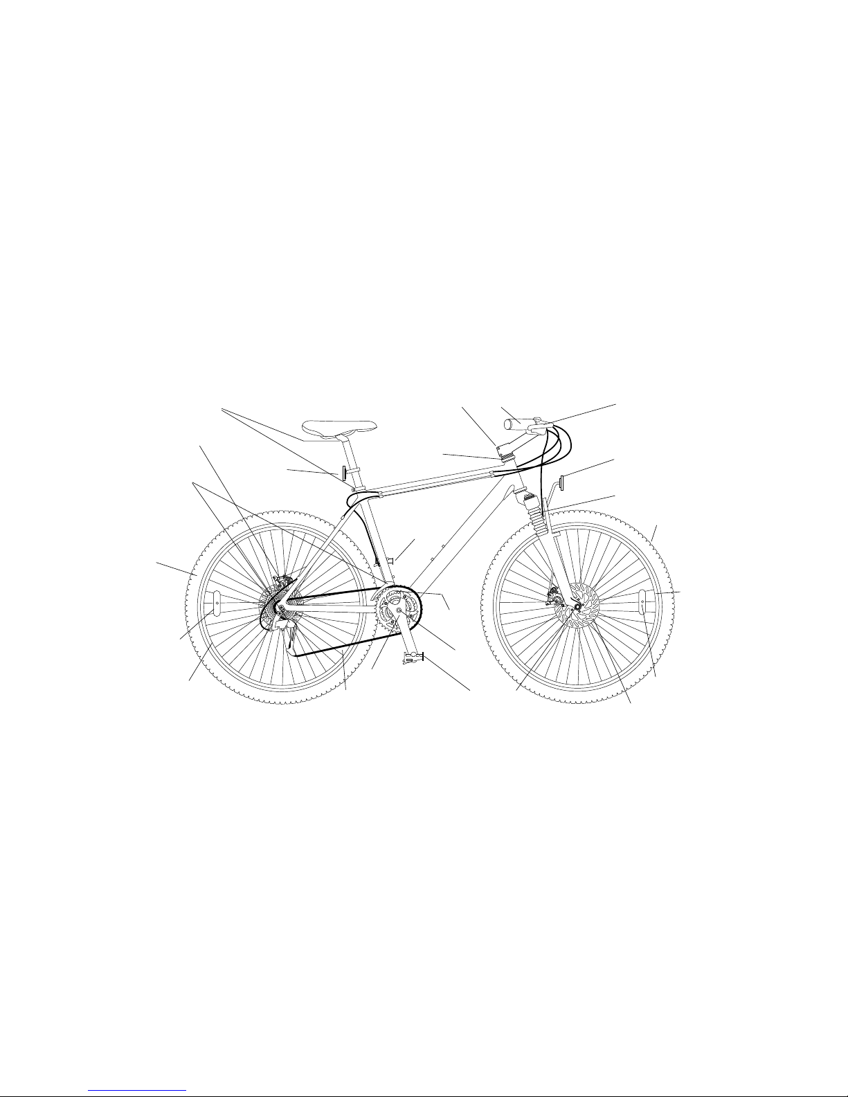
LOCATION OF PARTS WITH
ROUTINE MAINTENANCE CHECKS AND LUBRICATION
R
Q
P
Half Yearly — Remove and clean, lubricate chain, derailleur gears and all cables. Check and replace as required.
Refer to table of Recommended torque values - page 7.
O
N
N
M
L
K
S
J
I
H
H
G
G
F
E
E
D
C
B
A
NB — Wash cycle weekly with warm soapy water and polish dry with a soft cloth
T
3
A - Headset
Remove, clean and regrease
bearings yearly, checking if
replacements required.
B -
Stem Nuts
Ensure stem nuts and bolts are
tight. See page 7.
C -
Handlebars
Check handlebar bolt is tight.
Check brake levers securely
mounted to bars and brakes stop
smoothly and efficiently. See
page 7.
D -
Brakes
Lightly oil exposed cables
monthly. Maintain adjustment and
replace brake blocks when worn,
brake cables when frayed.
E -
Reflectors (front & rear)
Ensure reflectors are secure
and undamaged. Replace if
necessary.
F -
Front Suspension unit
(Dealer adjustment only)
G -
Tyres
Check for cuts and wear.
Maintain pressure indicated on
tyre wall for maximum efficiency.
H - Wheel
Reflectors
Check monthly. Securely fixed.
I -
Disc Brakes - Front
(Routine maintenance by your
dealer recommended.)
J -
Wheel Hubs
Grease bearings monthly. Adjust
cones to avoid free play from
side to side.
K - Pedals with Reflectors
Check all fittings are secure.
L - Cranks
Grease bearings monthly. Check
that axle bolts or cotterpin bolts
are tight. Check for free play in
bottom bracket.
Yearly, remove, clean and
regrease hub axles, bottom
bracket set and headset.
M - Chain
Keep lightly oiled weekly, clean
and lubricate half yearly.
N - Wheels
Check that axles are sealed
and secured properly. Rims
should be kept free from wax, oil,
grease and glue. Check for loose
or missing spokes.
O - Bottom Bracket
Clean, regrease yearly checking
for wear.
P -
Gears
Front and Rear — Lightly
oil moving parts. Maintain
adjustments of front and rear
derailleurs.
Q -
Disc Brake - Rear
(Routine maintenance by your
dealer recommended).
R - Seat and Stem Nuts
Be sure seat and
stem nuts are tight. See page 7.
S - Pedals
Lightly oil bearings monthly.
T - Frame Number
Page 4
SAFE CYCLING AND SAFETY TIPS
Before you ride your bicycle at any time make sure it is in a safe operating condition. Particularly
check that your:-
• Bicycleʼs nuts, bolts and parts are tight and not worn or damaged.
• Riding position is comfortable.
• Brakes are operating effectively.
• Steering is free with no excessive play.
• Wheels run true and hub bearings are correctly adjusted.
• Wheels are properly secured and locked to frame/fork.
• Tyres are in good condition and inflated to correct pressure.
• Pedals are securely tightened to pedal cranks.
• Gears are correctly adjusted.
• All reflectors are in position.
After you have made any adjustments to your bicycle, check that all nuts and bolts are securely
tightened and cables are free from kinks and fixed securely to the bicycle frame.
Every six months (more frequently if high mileage or subject to heavy use) your bicycle should
be professionally checked to ensure that it is in correct and safe working order. A ʻService
Recordʼ is provided for your use.
Do Notʼs when riding
• Do not ride on same side of road as oncoming traffic.
• Do not ride two abreast.
• Do not carry a passenger unless cycle is equipped to do so.
• Do not swerve in and out of traffic.
• Do not hang items over the handlebars to impede steering or catch in the front wheel.
• Do not hold on to another vehicle.
• Do not ride too close behind another vehicle.
CAUTION: Wet Weather Riding No brakes work as well under wet or icy conditions as they do
under dry conditions. In wet weather special precautions must be taken to assure safe stopping.
Ride slower than normal and apply your brakes well in advance of anticipated stops.
CAUTION: Night Riding We recommend you minimise the time you ride after dark. If you
should have to be out on your bicycle at night you must to comply with the law, use a headlight
(white) and a taillight (red) on your bicycle in addition to the all-around reflectors that are
fitted. For added safety wear light coloured clothing with reflective stripes. Check that the
reflectors are firmly secured in their correct position and clean and not obscured. Damaged
reflectors must be replaced immediately.
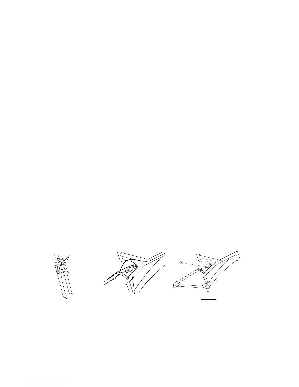
CAUTION: Suspension Units Your cycle may be fitted with suspension units built into parts
of the frame and forks. We recommend these are serviced by your dealer as required. More
details may be found in the suspension manufacturerʼs handbook.
Front Suspension Unit
Frame Suspension Unit
Pre Load Adjustment
We recommend that Pre-Load load for optimum safe riding should be set as follows.
1 Pre-Load alters the amount of bottom bracket drop when seated on the saddle. We
strongly recommend you set Pre-Load so as to experience no more than 1" (25mm) of
sag. Measured as a decrease in bottom bracket height.
To adjust Pre-Load, grasp knurled adjuster (A) and spring, and either:
2 Increase Pre-Load by turning to compress the spring
3 Decrease Pre-Load by turning to allow spring extension.
Riding Position
It is important that you and your bicycle are fitted to each other, not only for comfort and riding
ease but for control and safety. Normally your Dealer will custom fit your bicycle to you but the
following few pages should help you to find your most comfortable, safe and efficient position.
4
Bottom Bracket Height
Pre Load Adjust
Page 5
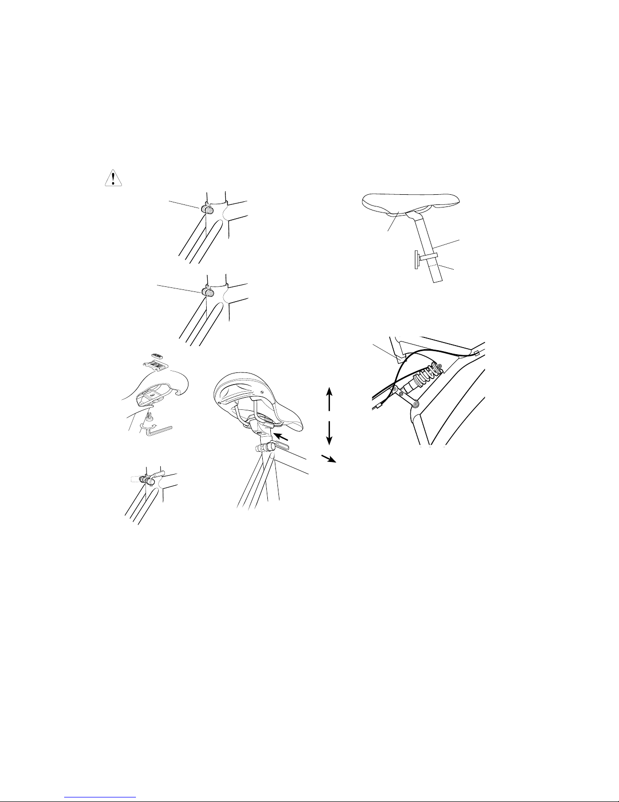
SEAT
Seat Adjustment
Loosen the nut on the seat-post clamp enough to allow the saddle to move forward and back.
The seat can then be aligned forward and back and the angle can also be adjusted (it is
recommended that the seat be parallel to the ground).
To adjust the seat up and down, loosen the binder-bolt on the seat tube, position the seat and
re-tighten the binder-bolt.
CAUTION: Insert the seat-post to a point above the insertion mark. The MINIMUM INSERTION
MARK should not be visible. Securely tighten the seat-post binder bolt/nut by using a 6 mm Allen
key or a 13 mm spanner. Test by grasping the seat and attempting to turn. Keep tightening until
the seat will no longer turn.Please refer to table of torque values Page 7
WARNING: Bicycle should not be ridden if seat adjustments are not properly tightened.
5
Allen head
Binder-bolt
Normal 13mm
Binder-bolt
Saddle
Seat Post
Minimum
Insertion mark
Seat posts differ according to saddle types
and accordingly the procedure for fitting
varies. If in doubt consult your dealer.
Close
Op
en
Seat Forwards
or Backwards
Seat Angle
End of
Seat Pillar
Seat Pillar adjustment—
Suspension frames.Take care
when inserting seat pillar that the
protruding end cannot interfere
with the frame suspension unit
during use. If in doubt consult
you dealer about adjustment.
CYCLING POSITION — Seat
Saddle Angle
The seat should be horizontal or parallel with the ground. Slight variation around the horizontal
may suit individual comfort but if excessive angles are felt necessary check other aspects of your
position.
Saddle Height
The correct seat height is determined by sitting on the seat with your leg fully extended. Your
heel (in flat shoes) should just touch the pedal when it is positioned at its lowest point. When
riding normally with the ball of your foot on the pedal your knee should be slightly flexed at the
bottom of the pedal stroke (see diagram following).
Saddle Forwards/Backwards Position
With the ball of one foot on the pedal and the cranks parallel to the ground the saddle should
be adjusted backwards or forwards to a position whereby the pedal centre is directly below the
knee joint.
Very small changes in saddle position can have a substantial effect on performance and
comfort. Consequently, whenever you make a change to your saddle position, make only
one directional change at a time and make the changes in small increments, until you have
found the point at which you are most comfortable.
Page 6
6
Knees slightly
bent
Handlebar Stem
approximately level
with seat or slightly
lower
Pedal at bottom
position
Loosen saddle from seat
pillar to adjust forwards
or backwards. Tighten
when set correctly
The saddle should be moved forwards or backwards so that the
knee is directly above the pedal when the crank is parallel to
the ground.
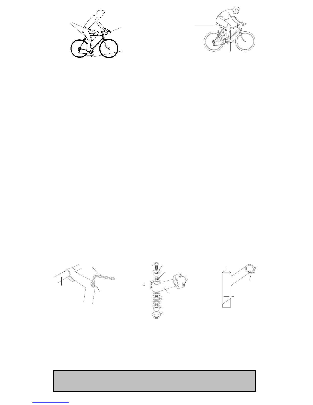
HANDLEBARS AND STEMS
As your cycle may be fitted with a standard ʻquillʼ stem or an A-Head stem, you must always check
that all the bolts are tight before cycling.
STANDARD STEM
: Loosen expander bolt so that expander wedge is not tight in bottom of
handlebar stem. Gently tap the top of the expander bolt to further loosen the wedge if necessary.
When the expander wedge is loose, move the handlebars up or down until you find the optimum
height at which you can easily reach the brake levers and comfortably grasp the handlebars. Usually
this height is level with, or slightly lower than, the top of the saddle. Be sure the stem is in line with
the front wheel.
CAUTION: A minimum insertion ring is marked on the handlebar stem and this marking
should remain in the head tube. Under no circumstances should the minimum height
insertion mark be visible on the handlebar stem. It must be down in the head tube.
When desirable height has been achieved, align the handlebar with the front wheel and securely
tighten expander bolt. It is extremely important to tighten the expander bolt sufficiently, so that when
the wheel is held between your legs and the handlebars are twisted, the handlebars do not move.
Do not over tighten, as it may increase risk of injury to the rider. Position grip portion of handlebars
horizontally and securely tighten the binder bolt.
Note: On models equipped with stem mounted gear levers the levers may be moved up or down to
the riderʼs most comfortable position. When moving them, be certain that the levers face upwards
and that the cables are not twisted.
Refer to table of recommended torque values on page 7.
Note: Whenever the handlebar stem is removed from the head tube then the expander bolt should
be lightly greased.
Note: On some ATB’s raising the stem requires brake cable adjustment. Do not attempt this if low
profile brakes are fitted with a stem mounted cable stop.
A-HEAD STEM
: Has 2 steerer clamp bolts on the back of the stem, which clamp around the
steerer tube. Loosen these bolts to align the stem with the front wheel. Re-tighten the steerer
clamp bolts.
CAUTION: Do not adjust the top compression bolt, this should be pre-set to eliminate bearing
play, overtightening will cause premature wear.
Contact your retailer for service.
Handlebar Position
The position of the handlebar should be set to allow a comfortable and easy reach of gear control
and brake levers.
When riding, your weight should be so balanced that your hands rest lightly on the handlebars.
This prevents strain on wrists and forearms when pedalling. If you alter the riding position,
remember to tighten all nuts and bolts securely
.
Refer to table of recommended torque values - page 7.
CAUTION:
NEVER EXTEND THE HANDLEBAR STEM OR SEAT POST ABOVE THE MINIMUM INSERTION
MARK AS THIS IS DANGEROUS
6mm Allen Key
Handlebar
Stem Expander Bolt
(Allen Head)
Recessed Type
Minimum
Insertion
Mark
Stem
Binder
Bolt
Stem Expander
bolt
Standard Stem
Steerer
Clamp Bolts
A-Head Type
Compression Bolt
Compression Cap
Extension
Spacers
Bearing Seat
Top cup with Bearings
inside
5 Star Washer
Stem Binder
Bolts
Page 7

COTTERLESS CRANKS ADJUSTMENT
IMPORTANT
Please check if the chainwheel and cranks of your new bicycle are of the cotter less type
as illustrated on page 3.
If so, to ensure trouble free operation it is important that the nuts securing these item to the
bottom bracket axle are tightened as securely as possible.
It is strongly recommended that the tightness of the nuts be checked after the first two
weeks of use and a maximum of three monthly intervals thereafter.
BRAKES
WARNING
For safe riding it is important to completely understand the operation of your bicycleʼs
brake system. Improper use of your bicycleʼs brake system may result in a loss of control or
an accident, which could lead to severe injury. Because each bicycle may handle differently,
be sure to learn the proper braking technique (including brake lever pressure and bicycle
control characteristics) and operation of your bicycle. This can be done by consulting your
professional bicycle dealer and this ownerʼs manual, and by practicing your riding and
braking technique.
The bicycle is equipped with two independant brake mechanisms. One on the front wheel
and the other on the rear wheel. The brakes are operated by hand levers fastened to the
handlebars. The right lever controls the front brake and the left lever controls the rear brake.
To stop with safety:
1. Operate the rear brake (left lever) slightly before the front brake (right lever).
2. Apply firm pressure to both front and rear brake levers.
CAUTION: If the front brake is applied with too much pressure, the rider may be thrown off
the bicycle.
3. Never apply the front brake on a turn. This is especially dangerous when cornering or
riding on slippery or loose surface roads.
CAUTION: Brakes are less effective in wet weather. Ride slower and allow more distance
for stopping.
Note: Do not ride your bicycle if the braking system is not working correctly. If you are in
doubt, take your bicycle to your dealer.
7
TABLE OF RECOMMENDED TORQUE VALUES
DESCRIPTION TORQUE
1 Stem Expander Bolt 20Nm 15lb-ft
(where fitted)
1A A-Head Steerer Clamp Bolts 10Nm 8lb-ft
(where fitted)
2 Stem Binder Bolt 10Nm 8lb-ft
3 Brake Fixing Bolt (non disc) 5Nm 4lb-ft
Applies to both front and rear brake
4 Front Axle Nut 30Nm 22lb-ft
5 Chain Wheel Securing Bolt 38Nm 28lb-ft
6 Pedal 40Nm 30lb-ft
7 F/Derailleur Cable Fixing Bolt 4Nm 3lb-ft
8 R/Derailleur Cable Fixing Bolt 4Nm 3lb-ft
9 Rear Axle Nut 30Nm 22lb-ft
10 Seat Pin
(Hexagonal Head) 10Nm 8lb-ft
Seat Pin
(Allen Head) 10Nm 8lb-ft
11 Front and Rear 3Nm 2.5lb-ft
Reflector Mounting Nut
12 Saddle Clamp Bolt
(Hexagonal Head) 15Nm 11lb-ft
1A
1
2
3
4
5
6
7
8
9
10
11
12
13
Page 8

BRAKE ADJUSTMENT PROCEDURE — Caliper brakes
The brakes on your bicycle should have been adjusted correctly by your dealer; however, as
cables do stretch, it is important to check the adjustment of your brakes after your first ride. Most
brakes will need some adjustments after being used the first few times. Your brakes are correctly
adjusted when there is a 1.5 mm gap between the brake blocks and the brake track of the wheel
rim.
Do not adjust brakes to allow brake blocks to contact wheel rim when brake levers are in the off
position. The fine adjustment of the brakes is made by the following procedure:
1. Turn adjustor A to set blocks C just clear of rim by 1.5 mm.
2. Ensure that the brake blocks meet the rim parallel and central to the rim brake tracks. Adjust
by nuts D if necessary, then tighten securely.
3. When all fine adjustment is taken up on adjustor A, it will be necessary to reset the cables as
follows:
a. Turn adjustor A all the way down as far as it will go into its mounting.
b. Loosen cable clamp bolt B. Press both brake shoes firmly against wheel rim.
c. Pull brake cable wire through its clamp bolt.
d. Tighten cable clamp bolt B securely.
Note: If one brake shoe is closer to the rim than the other first check that the wheel has been
centred between the forks then adjust the brakes as necessary.
To adjust brakes that have central Caliper adjuster simply turn screw as shown until brakes
centralise.
BRAKE MAINTENANCE — Caliper brakes
To maintain cable brakes in efficient working order, regularly check the brake adjustment and
lightly lubricate brake pivots and springs. Oil the exposed parts of the cable to prevent corrosion.
Slow or inefficient braking often indicates that the brake cables themselves require lubrication.
As this job requires the removal of the complete brake cable, we recommend strongly that this
service is done professionally.
Note: To assure smooth braking, wheels must run true and be correctly adjusted, with the rim
brake tracks free from dents and kinks. The brake blocks should be in correct alignment with the
rim brake track. See your dealer if you are in any doubt
regarding wheel and brake adjustment.
Protect yourself from frayed cable ends by maintaining the
end pieces fitted over the cable ends.
Brakes should function freely and release fully. If brakes bind,
first check for clean-liness and proper lubrication. If brakes
still bind, return your bicycle to your dealer for adjustment.
8
To centre side pull brakes first slacken the retaining nut and then centre the brake using a
spanner on the front retaining nut.
CAUTION: Before riding, test your brakes. Make sure that the quick release mechanism is
returned to its normal correct position, otherwise your brakes will not operate effectively.
Calliper Arm
Tyre
Wheel Rim
Brake Shoe
Brake Shoe
Quick Release
Mechanism
Return Spring
Page 9

1. Pass the inner cable through the inner
cable lead, and after setting so that the total
of the clearances between the left and right
shoes and the rim is 2 mm, tighten the cable
fixing bolt.
To release the brake inner cable from the V brake, squeeze the two brake arms together until the
brake blocks contact the rim and remove the inner cable pipe from the cable end bracket.
To re-connect again squeeze the two brake arms together and relocate the inner cable pipe in
the cable end bracket.
INNER CABLE ADJUSTMENT
INNER CABLE QUICK RELEASE
ʻVʼ BRAKE SYSTEM
9
2. Adjust the balance with the spring tension adjustment screws.
BRAKE MAINTENANCE — Disc Brakes
Your cycle may arrive with factory fitted disc brakes — the latest technology in cycle braking!
If you have purchased your cycle from a professional cycle shop your brakes should have been
set up correctly. You will only have to do routine maintenance as the brake pads wear. (This is
described later on in this section).
If you purchased your cycle from a mail-order source you may have to set up the brakes before
you use your cycle.
The notes that follow are not exhaustive. If you need further assistance, please refer to the disc
brake leaflet that should accompany the cycle. If you do not have such a leaflet please take your
cycle to a professional cycle shop.
BRAKE LEVER AND BRAKE PAD TRAVEL ADJUSTMENT.
You can alter the amount of braking pressure by altering the travel of the brake lever and by the
proximity of the brake pads to the brake disc.
To alter the travel of the brake lever adjust screw A (see Fig.
1). Unscrewing screw A reduces the amount of lever travel
and by tightening it increases the lever travel. If you have fully
unscrewed screw A and the lever travel is still excessive you will
have to adjust the space between the pads and the disc.
A
Fig.1
Inner Cable Lead
Pipe
Cable End
Bracket
Cable Fixing
Bolt
3. Depress the brake lever about 10 times as in normal brake
operation and check that everything is operating correctly and
that the shoe clearance is correct before using the brakes.
Depress about
10 times
BRAKE BLOCK REPLACEMENT- Caliper and V Brakes
All brake blocks are provided with grooves that indicate the
wear on each block. When the grooves are worn down to a
flat surface, replace the blocks(in pairs) immediately.
Wear Indicator Groove
Page 10

BRAKE LEVER AND BRAKE PAD TRAVEL ADJUSTMENT — cont.
Tighten screw A (Fig. 1) up to the brake lever. Go to Fig. 2 and insert a 2.5mm Allen key into
the smaller hole inside allen key hole B. Rotating the allen key clockwise pushes the outer
brake pad forward by approx. 0.8 mm. After each turn, check the brake travel, and the braking
Once the correct amount of travel has been reached, centre the brake Calliper on the disc by
adjusting screw C (Fig. 3). When the brake pads are centered on the disc the wheel should spin
freely, though there may be a slight amount of noise until the pads “bed” in.
If your cycle came from, or has recently been overhauled by a professional repair shop, you
B
Fig.2
Smaller
keyhole inside
main hole.
C
Fig.3
BRAKE PAD WEAR AND REPLACEMENT
When you check your brake pads due to
falling performance, check their thickness.
If they are less than 1 mm thick (Fig. 4) they
will need replacing.
1 mm
Min
Fig.4
To fit new pads, remove the brake Calliper
from the fork or frame by unscrewing allen
bolts D (Fig. 5). Unscrew, (anti-clockwise),
the smaller allen bolt inside allen bolt B
(Fig. 2). Lift up and pull the inner pad
downwards, using the protruding part E
(Fig. 6). Slide a thin slot screwdriver under
the outer pad (Fig. 7) and lift it up. Hold the
screwdriver in this position and remove the
pad with a pair of long-nosed pliers
D
Fig.5
10
Page 11

Remove the springs from the the worn out pads and fit them onto the new pads. Replace the
new pads, keeping them slightly inclined, into the seat of the Calliper. Check that the spring
hooks correctly onto the small piston. (When pulling downwards the pads should not come out).
Refit the Calliper to the fork or frame and adjust screw C (Fig. 3) until the pads and the disc are
centered and the wheel spins freely. (Again there may be some noise from the brake until it “beds
E
Fig.6 Fig.7
DERAILLEUR GEARS INTRODUCTION
The derailleur gear is so named because it works on the derailing principle to move the chain
from one sprocket to another. The number of gears is determined by multiplying the number of
sprockets on the rear freewheel by the number of chainrings on the front crank set.
By using different combinations of sprocket and chainwheel sizes, a wide range of gear ratios are
available. The highest gear is when the large chainwheel is coupled with the small sprocket and
the lowest gear is when the small chainwheel is combined with the largest rear sprocket.
The wide range of gears allows you to combat all prevailing conditions while pedalling at the
constant and efficient rate of sixty revolutions per minute.
DERAILLEUR GEAR MAINTENANCE
To help ensure that your derailleur gear works efficiently and to prolong its life, it must be kept
clean and free from excess dirt build up and should be properly lubricated.
GEAR CHANGING
The riderʼs left gear lever controls the front derailleur and chain wheels.
The right gear lever controls the rear derailleur and sprockets.
The large rear sprockets generate low gears for hill climbing. The small rear sprockets develop
high gear ratios for speed work and downhill riding.
The small front chainring produces low gear ratios while the larger front chainrings produce
higher gear ratios.
To operate your derailleur gear system efficiently and reduce damage, wear and reduce noise to
a minimum, avoid using the maximum crossover gear ratios of large chainring/large rear sprocket,
small chainring/small rear sprocket.
CAUTION: For positive gear selection, observe these four precautions:
1. Change only when pedals and wheels are moving in a forward motion.
2. Reduce pedal pressure while changing gears.
3. Never back pedal when changing gear.
4. Never force the gear levers.
Gear selection should be made in anticipation of need since forward motion of the bicycle is
required when changing gear. It is advisable to change to a low gear before stopping in order to
be in the proper gear when you start up. On hills, change gear early while still maintaining forward
pedalling speed.
11
Page 12

12
SIS ADJUSTMENT
If your bicycle is equipped with the Shimano Index System (SIS) you can pre-set the gear shifter
to change gear simply by clicking the shifter up or down to the required gear. The next few pages
and diagrams show how to set this up (if your dealer has not already done it). If you have any
problems you should get your dealer to set the SIS up.
Top adjustment
Turn the top rear adjustment screw on the gear mechanism so that, looking from the rear, the
guide pulley is below the outer line of the top gear.
Low adjustment
Turn the low gear adjustment screw so that the guide pulley moves to a position directly below
the low gear.
1. Operate the shifting lever to shift the chain from the top gear to 2nd gear.
*If the chain will not move to the 2nd gear, turn the cable adjusting barrel to increase the
tension 1 (counter clockwise)
*If the chain moves past the 2nd gear, decrease the tension 2 (clockwise)
CABLE
ADJUSTMENT
BARREL
TOP2nd
3rd
Be sure to perform oil maintenance at each part of the transfer mechanism. The optimum oil is
dry molybdenum oil or the equivalent.
LOW
ADJUSTMENT
SCREW
LOW GEAR
GUIDE
PULLEY
TOP
ADJUSTMENT
SCREW
TOP GEAR
OUTER SLIDE
GUIDE
PULLEY
COUNTER
CLOCKWISE
CLOCKWISE
CABLE ADJ.
BARREL
1
2
2. Next, with the chain on the 2nd gear,
increase the inner cable tension while turning
the crank forward. Stop turning the cable
adjusting barrel just before the chain makes
noise against the 3rd gear. This completes
the adjustment.
Front Derailleur
The adjustment of the sideways movement of the front changer is by means of two gear stop
screws situated on the body of the changer mechanism. The inner screw limited the inner travel
of the changer cage, the outer limits the outward movement
Use the following procedure for adjustment:
1. While turning the pedals forward select the middle (on a triple chainset) or the top chainring
then select the smallest rear sprocket.
2. While turning the pedals adjust the inner screw on the front changer so that the chain will just
drop into the lower ring with the gear lever fully forward.
3. Select the largest rear sprocket. If there is any evidence of chain rub adjust the inner screw
until this just ceases.
4. With the chain still on the largest rear sprocket select the ring below the largest at the front.
Adjust the outer screw so that the chain just selects the outer chainring when the gear lever
is moved through its full arc range.
Page 13

13
5. Select the smallest rear sprocket, if there is any evidence of chain rub adjust the outer screw
until this just ceases. The lower edge of the outside plate should be positioned approximately
1-3 mm above the largest outside chainring. If a biopace chain set is fitted as indicated on the
chainring the clearance should be measured above the highest point of the ring.
6. If a chainwheel disk is fitted, make sure there is sufficient clearance between changer cage
and chainwheel disk.
7. If problems continue to arise, the bicycle should be checked by a professional repairer.
1-3mm
Inside front changer
Chainwheel dis
k
Adjusting screws
Operating wire
from left hand
gear control
Outside front changer
Outside Chainwheel
Middle Chainwheel
Inner Chainwheel
VIEW FROM SIDE
Outer adjusting screw
sets outer movement limit
Chainwheel disk
Front changer cage
Inner adjusting screw
sets inner movement
limit
Using the adjusting screws set the limit for the
movement of the front changer cage
VIEW FROM ABOVE
STI RAPIDFIRE
STI Rapidfire lever uses two push levers mounted conveniently under the bar in front of the
thumb. Using lever (A) you can shift one gear at a time, or shift down the entire block with a full
stroke push. Using lever (B) you can shift up the sprocket with the same capability.
STI OPERATION
Rear Gear Operation
Right Hand Lever.
Lever (A) — operated
by your right hand
thumb pressing away
from your body (shifting
from a small sprocket to
a larger sprocket)
2) To shift two gears at a time
from a small sprocket to a larger
sprocket press Iever A twice
Example: from 2nd to 4th
3) To shift three gears at a
time from a small sprocket to
a larger sprocket press lever
A three times
Example: from 2nd to 5th
Lever (B) - operated by pulling with your your right hand forefinger or pushing with
your thumb depending on model of shifter. (shifting from a large sprocket to a small sprocket)
When lever (B) is pulled once,
there is a one-step shift from a
larger gear to a smaller gear
Example: from 3rd to 2nd
1
2
3
Clic
k
Click
Click
Right hand lever viewed from below
Right hand lever viewed from below
1) To shift one gear at a time
from a small sprocket press
lever A once
Example: from 2nd to 3rd
3 2
4 2
5 2
3 2
Rear gear changer. Right hand lever
Lever B
Lever A
Page 14

14
STI OPERATION
Front Gear Operation
Lever (A) - operated by your left hand thumb pressing away from your body (shifting from a small
chainwheel to a larger chainwheel)
When it is pressed once, there is a shift of one gear
from a smaller chainwheel to a larger chainwheel.
Example: from mid-range to largest chainwheel
Lever A
Lever (B) - operated by pulling with your left hand forefinger or pushing with your thumb
depending on model of shifter.
(shifting from a large chainwheel to a smaller chainwheel)
If your front gears do not operate smoothly, it may be that your front gear cable and front changer
need adjustment. You can adjust your front gear cable by using the outer adjustment bolt on the
left hand lever. This will adjust your front changer so that it has minimum clearance between the
chain and the inside left hand side of the chain guide.
When it is pulled once, there
is a shift of one gear from a
large chainwheel to a smaller
chainwheel.
Example: from largest
chainwheel to mid-range
Cable tension adjustment
1. Set the chain to the largest rear sprocket, and, at the front, use the Rapidfire to shift from the
largest chainwheel to the intermediate chainwheel.
Shift
Largest chainwheelLargest sprocket Largest sprocket Intermediate chainwheel
2. Adjust, by using the outer adjustment bolt, so that there is the
minimum clearance, but so that the chain and the plate (inside the
chain guide) do not contact.
Minimum clearance
between chain and
inside left of change
r
A B
Front gear changer. Left hand lever
Outer adjustment bolt
Front gear changer. Left hand lever
Lever B
Lever A
You can shift the triple front chainwheels with the same precise STI action, 1 or 2 chainwheels at a
time, using levers (A) and (B) on the left hand lever
Left Hand Lever.
Page 15

15
Never remove the lever cover.
Do not loosen the lever cover installation bolt.
Lever (B)
New Cable
Old Cable
Right hand lever, rear gear
Gear Inner Wire Replacement & Connection
STI Adjustment — Noise prevention mechanism
If chain noise occurs, due to overshifting,
when a shift is made from the smallest
chainwheel to the intermediate
chainwheel, the overshifting can be
adjusted by gently pressing lever (b) to
move the front derailleur slightly toward
the small chain wheel, thus activating
the noise prevention mechanism.
Installation to the Handlebar
Move lever (a) (and lever (A) when
installing the right hand lever) so that
the installation bolt can be seen and
then use an Allen key to install a torque
of 6 - 8 Nm (4.5 - 6lb-ft).
Allen Key
Lever b
Lever (a)
Press Lever
(a) to
reveal the
installation
bolt
Left hand lever operating front
gear changer viewed from below
Installation of the brake cables
Use the 1.6 mm diameter inner cable and the 5 mm diameter outer casing.
1. Insert the cable barrel nipple through the brake lever body.
2. Mount the nipple into the retaining hole in the lever.
3. Ensure the brake adjusting bolt and nut are seated correctly in the lever.
4. Adjust the lever adjustment screw to obtain the desired grip width
5. Before riding, test the brakes several times to ensure everything is seated correctly and
that the brakes are functioning properly. Readjust as necessary.
IF IN DOUBT ABOUT BRAKE FUNCTIONING
CONSULT YOUR LOCAL DEALER.
Wire holding plate
Holding nut
Groove
Outer adjustment bolt
Dust Cover
Lever adjustment
screw
Left hand lever viewed from below
Cable barrel nipple
Adjust grip width
using lever adjustment screw
For the rear, press lever (B) six times or more, and then, for the front, press lever (b) three or
four times.
Push out the old cable through the lever cover and replace with the new cable.
Left hand lever, front gear
Lever (b)
New Cable
Old Cable
Page 16

16
GRIP SHIFT Service Instructions
Lubrication
If re-greasing should become
necessary due to excessive
exposure to water and grit:
1. Disassemble and wash parts in
kerosene or degreaser. Blow parts
clean with compressed air before
lubricating.
2. Using a silicone based teflon
grease, apply to areas shown. Phil
Wood waterproof grease may be
substituted.
Cable Changes
1. Rotate Grip Shift until cable is fully released and disconnect cable from derailleur.
2. Remove cover.
3. Separate Grip Shift assembly by pulling outward. The spring may unseat from the spring
cavity.
4. Remove and discard old cable.
5. Lubricate shifter before reassembling. See “Lubrication” above.
6. Replace with Grip Shift approved cable only. Thread new cable through housing cable inlet
hole.
Around tube
Spring Cavity
Cable Groove
Cable Inlet Hole
Housing
Spring
Grip
Cover
All
Detente
Notches
Cable
Grooves
GRIP
7. Loop the cable around housing. Exit cable through barrel adjuster.
8. Put the spring in spring cavity. If necessary apply a small amount of grease to hold spring
in place.
9. Slide grip over housing. Rotate grip to align
gear indicator mark with the largest number
on grip. Lift the loop of cable off the housing
and lay the cable into the groove in grip.
Push the grip inward while pulling the cable
out of the barrel adjuster until grip is flush
with housing.
10. Replace cover.
11. Check for proper assembly by rotating grip
and listening for indexing clicks.
12. Adjust indexing per derailleur manufacturers specifications.
Housing
Grip
Cover
Groove
WARNING: Do not use lithium grease
Page 17

17
REVOSHIFT
MOUNTING THE SHIFTING LEVER
Install the brake lever in a position where it will
not obstruct brake operation. Do not use in a
combination which causes brake operation to
be obstructed.
Tightening torque:
2 Nm (1.5lb -ft)
Suitable
Allen Key
Suitable
Allen Key
GEAR SHIFTING OPERATION
REPLACING THE INNER CABLE
1. Turn the lever to the initial position (low position
for the front lever; top position for the rear lever).
2. Loosen the lever fixing bolt, and then rotate the lever until the cover
fixing bolt can be turned (Fig. 1)
After this, remove the cover fixing bolt and then remove the cover (Fig 2)
3. Pull out the inner cable and replace it with the new inner cable (Fig. 3)
4. After installing the cover, rotate the lever to return it to its original position, then tighten the
lever fixing bolt.
Lever fixing bolt
Cover fixing bolt
FIG. 1
FIG. 2
Inner Cable
FIG. 3
Pedalling
becomes
heavier
Pedalling becomes
lighter
Pedalling
becomes
lighter
Pedalling
becomes
heavier
Page 18

18
TYRE CARE AND WHEEL ADJUSTMENTS
To obtain maximum life and full benefit from your tyres, it is essential to maintain the
recommended pressure indicated on the tyre sidewall.
Unnecessary hard braking and skidding greatly reduces tyre life. Make sure your tyres do not
come into contact with oil, petrol, paraffin or other rubber solvents.
Make sure that your wheels run true and are in correct alignment to avoid chafing the tyre
sidewall against the bicycle frame or fork tubes.
Tyres should regularly be inspected for wear and cuts. Check that the tyre tread pattern is clearly
showing all around the outside edge of the tyre. Check there are not any breaks, cuts or uneven
wear in the tyre. Tyres should be replaced if damaged.
Tyre punctures can be caused by careless riding over sharp stones, holes in the road, or by
hitting curbstones
If you are storing your bicycle for a long period of time, it is advisable to store the machine with
the tyres off the ground to prevent them from becoming distorted.
To inflate tyres, a foot pump or normal bicycle inflator fitted with a suitable valve connector should
be used along with an accurate tyre pressure gauge.
Wheels should be checked regularly for spoke tension. Perform this check more frequently if the
bicycle is used on rough roads.
STANDARD REAR WHEEL - ADJUSTMENT AND REMOVAL
To Remove Wheel
Move the chain onto the smallest rear sprocket. Disengage the brake quick release lever if your
bicycle is so equipped. Loosen both axle nuts by turning in a counter clockwise direction. Pull the
derailleur mechanism gear for additional clearance. Remove the rear wheel by sliding forward
and out of the frame.
To install wheel, locate the top section of the chain on the small sprocket and replace the wheel
into the frame by pushing back and centralising between the chainstays. While holding the wheel
in this position, tighten the axle nuts in a clockwise direction.
The wheel should turn freely and have very little side play.
Reset rear brake quick release mechanism and check brake for proper operation.
Quick Release Rear Wheel
Removal and installation of rear wheel fitted with quick release mechanism. Use same procedure
as for standard rear wheel, with the exception of loosening axle nuts. Operate the quick release
lever by pulling away from the wheel and turning release lever 180° to release the wheel.
When installing the rear wheel, use the same closing and adjusting procedure as outlined for
quick release front wheel.
Check quick release lever is in the correct and fully locked position before each ride.
Reset rear brake quick release mechanism and check brake for proper operation.
Front wheel
Remove axle nuts, washers, and axle retention
device if fitted. The axle cone bearing adjustment
should permit smooth rotation of wheel. Cone
locknut should be securely fastened against
axle cone to prevent loosening. Place the
front wheel between the fork blades with axle
retention device and the projecting prongs
of
the retention device securely fitting the slot in the
fork or with standard washers securely placed in
position on to the wheel axle in the place of the
retention washer.
Replace locking washers and nuts at both ends
gradually and alternately in order to keep the
wheel centered.
CAUTION:
Front wheel must be installed with retention
devices securely placed into slots of fork blades
or washers if fitted. This will ensure positive
locking of front wheel to front fork.
Retention device or standard washer
Nut
Nut
Axle
Nut
Front Hub
Cone
Front Fork
Retention
washer
(if fitted)
Cone Locknut
Page 19

TYRE CARE AND WHEEL ADJUSTMENTS CONTINUED
QUICK RELEASE FRONT WHEEL
1. To remove the front wheel, first release the front wheel brake. Then open the
quick-release lever on the axle and pull the wheel from the forks.
2. To install, fit wheel into forks with quick release lever on the left side. Close quick-
release, and tighten adjuster until snug. Release quick-release lever and further
tighten adjuster approximately 3/4 of a turn. Lock and check that the quick-release has
embossed the fork ends. It may be necessary to tighten or loosen the adjuster slightly.
Make certain to reset the quick-release front brake to ensure proper operation.
3. Wheel must be clear frame and fork by at least 1/16".
4. The wheel should turn freely and have very little side-play.
5. Check quick-release lever is correct and fully locked position before each ride.
FITMENT OF BELL
1. Remove screw from bell clamp.
2. Position in a convenient spot near the left hand or right hand handlebar grip.
3. Replace screw & tighten securely.
4. Rotate the “Ping Arm” to a comfortable position.
5. Check quick-release lever is correct and fully locked position before each ride.
Spring
Spring
Adjusting nut
Quick Release Lever
Closed
Open
Locked position
Retaining Device
WARNING! Do not attempt to ride the cycle until you are
absolutely sure that the quick release lever is fully closed and
securely tightened. Children should check with their parents to
ensure that this has been tightened correctly.
Ping Arm
Brake Lever/Shifter
Grip
Position Bell on left hand or right hand side of the handlebar as required.
19
Page 20

1. Fit to chainside of cycle.
2. The pedal tightens in a clockwise direction
3. Locate thread by hand, fit and tighten.
4. Use spanner to finish tightening (be careful)
Check for the letters “L” or “R” on the ends of the pedals to show which side the pedal needs to
be fitted to.
1. Fit to non chainside of cycle.
2. The pedal has a special thread to tighten in a anti-clockwise direction
3. Locate thread by hand, fit and tighten.
4. Use spanner to finish tightening (be careful)
R
L
R
Tighten Clockwise
L
Tighten Anti-clockwise
R
L
PEDAL IDENTIFICATION
TO FIT RIGHTHAND PEDAL
TO FIT LEFTHAND PEDAL
WARNING
20
 Loading...