

Page 1

THIS DOCUMENT IS AVAILABLE AT http://www.falcom.de/
Phantom
Hardware description (brief)
Preliminary/Draft
Version 1.00, 30/06/2005
Page 2

PHANTOM HARDWARE DESCRIPTION VERSION 0.01
Index of contents
0 INTRODUCTION .......................................................................4
0.1 GENERAL................................................................................................................................4
0.2 CIRCUIT CONCEPT...................................................................................................................5
0.3 PACKAGE CONTENTS...............................................................................................................5
0.4 RELATED DOCUMENTS ..............................................................................................................6
1 SECURITY .................................................................................7
1.1 GENERAL INFORMATION...........................................................................................................7
1.2 EXPOSURE TO RF ENERGY.........................................................................................................7
1.3 EFFICIENT MODEM OPERATION ..................................................................................................7
1.4 ANTENNA CARE AND REPLACEMENT..........................................................................................7
1.5 DRIVING .................................................................................................................................8
1.6 ELECTRONIC DEVICES...............................................................................................................8
1.7 VEHICLE ELECTRONIC EQUIPMENT..............................................................................................8
1.8 MEDICAL ELECTRONIC EQUIPMENT ............................................................................................8
1.9 AIRCRAFT ...............................................................................................................................8
1.10 CHILDREN ...............................................................................................................................8
1.11 BLASTING AREAS......................................................................................................................9
1.12 POTENTIALLY EXPLOSIVE ATMOSPHERES ......................................................................................9
1.13 NON-IONIZING RADIATION .......................................................................................................9
2 SAFETY STANDARDS.............................................................. 10
3 TECHNICAL DATA .................................................................11
3.1 GENERAL SPECIFICATIONS OF PHANTOM UNIT ...................................................................... 11
3.1.1 Power consumption ....................................................................................................... 11
3.2 TECHNICAL SPECIFICATIONS OF GSM/GPRS ENGINE ............................................................. 12
3.3 TECHNICAL SPECIFICATIONS OF GPS RECEIVER ....................................................................... 13
4 APPLICATION INTERFACE .....................................................15
4.1 DESCRIPTION OF THE 8-PIN ROW-CONNECTOR ........................................................................ 15
4.2 DESCRIPTION OF LED INDICATORS......................................................................................... 16
4.3 INTERFACES FOR EXTERNAL GSM/GPS ANTENNAS .................................................................. 17
4.4 BI-DIRECTIONAL KEYFOB, REMOTE OPERATION ........................................................................ 18
5 FIRST STEPS TO MAKE IT WORKS ...........................................20
5.1 MINIMUM SET-UP CONNECTION ............................................................................................. 20
This confidential document is a property of FALCOM GmbH and may not be copied or circulated without previous permission.
Page 1
Page 3

PHANTOM HARDWARE DESCRIPTION VERSION 0.01
Version history:
Version number Author Changes
1.00 Fadil Beqiri
- Initial version
This confidential document is a property of FALCOM GmbH and may not be copied or circulated without previous permission.
Page 2
Page 4

PHANTOM HARDWARE DESCRIPTION VERSION 0.01
Cautions
Information furnished herein by FALCOM are accurate and reliable. However, no
responsibility is assumed for its use.
Please, read carefully the safety precautions.
If you have any technical questions regarding this document or the product
described in it, please contact your vendor.
General information about FALCOM and its range of products are available at the
following Internet address: http://www.falcom.de/
Trademarks
Some mentioned products are registered trademarks of their respective companies.
Copyright
This manual is copyrighted by FALCOM GmbH with all rights reserved. No part of this
manual may be produced in any form without the prior written permission of
FALCOM GmbH.
FALCOM GmbH.
No patent liability is assumed with respect to the use of the information contained
herein.
This confidential document is a property of FALCOM GmbH and may not be copied or circulated without previous permission.
Page 3
Page 5
PHANTOM HARDWARE DESCRIPTION VERSION 0.01
0 INTRODUCTION
0.1 General
This description is focused on the GSM/GPRS and GPS unit Phantom from FALCOM
GmbH. It contains short information about purpose and use of the Phantom
concept. This guide completes information needed to prepare and build
applications incorporating the Phantom unit.
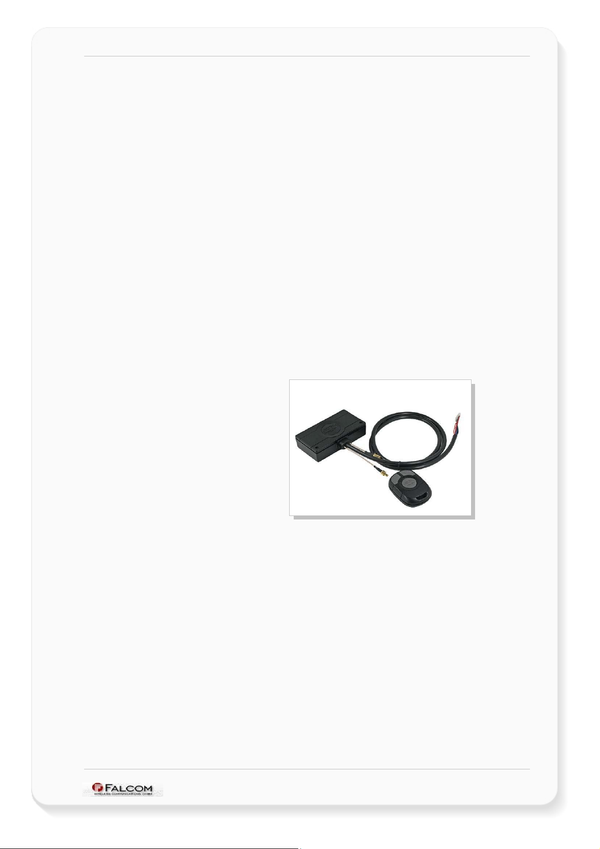
The Phantom unit is a Tri-band GSM/GPRS engine that works on the three
frequencies GSM 850/1800/1900 MHz. The integrated GPS receiver architecture
based on the SiRFstarIII chipset provides more then enough precise location
information using satellite signals to enable to track objects where the Phantom unit
is installed anywhere in the United States, Canada and Mexico. With its integral
housing, compact design and ultra-low power consumption, powered by a
rechargeable (3.7V/850 mAh) battery it is an outstanding quality, highperformance, operating as a stand alone unit. The configurable internal firmware is a
fundamental component which in combination with the excellent hardware
performance makes the Phantom unit to be on the top of applications where the
fleet management and objects safety and security today are required. The Phantom
unit consists of the GSM/GPRS engine, 20-chanel GPS receiver, IEEE 802.15.4,
Bluetooth™ class 2 and a 3-D motion detector (allowing it to run in low power and
Alarm mode) as an all-in-one solution.
Figure 1: View of PHANTOM unit
The embedded Class 2 Bluetooth™ transceiver is capable of communicating with
any Serial Port Profile Bluetooth™ device, within a 10m radius. The Phantom in
communication with your installed GPS Mapping software on the Bluetooth™enabled device points you the way comfortably and reliably from the current
location A to your desired destination B. The phantom allows you to navigate freely
without the hassle of messy wire connections.
A compact “stacked FLASH/SRAM” device stores the PHANTOM software in the flash
memory section of the GSM/GPRS part, and the static RAM section provides the
additional storage capacity required by GPRS connectivity.
This confidential document is a property of FALCOM GmbH and may not be copied or circulated without previous permission.
Page 4
Page 6
PHANTOM HARDWARE DESCRIPTION VERSION 0.01
0.2 Circuit concept
The PHANTOM architecture includes the following major functional components:
ARCHITECTURE INTEGRATES:
high-performance Tri Band GSM/GPRS core (operating at 26MHz)
20 parallel channel low-power GPS core (operating at L1 1575.42
MHz and C/A code 1,023 MHz chip rate)
ARM7TDMI Processor (at speed 25MHz) that controls all functions of
the system
Bluetooth connectivity
Integrated IEEE 802.15.4 wireless module (ZigBee Ready) for
communication with Kefob
3D detector system (MSENS module)
Power Control for Li-Ion Batteries
Combo-Memory (2MB - 512KB) for loading software.
PHYSICAL INTERFACES:
8-wires for user applications.
internal SIM card reader
GSM/GPRS antenna connector
GPS antenna connector
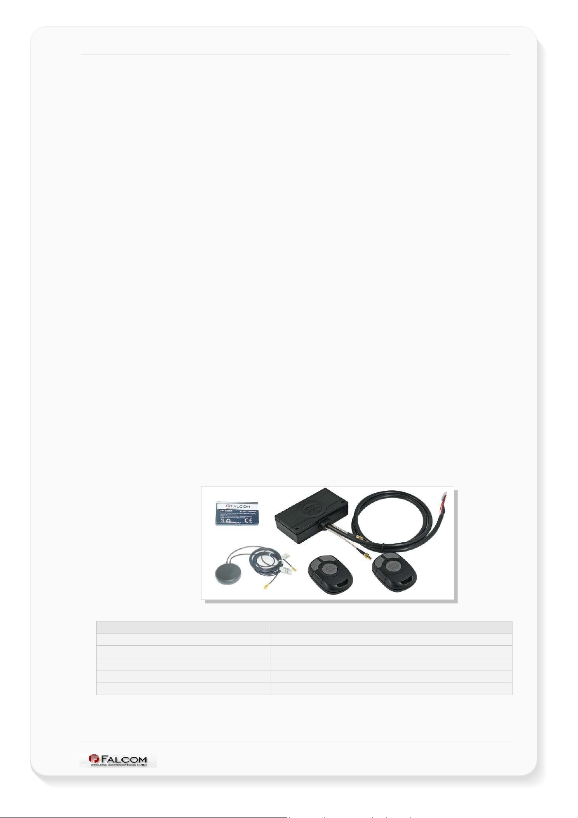
0.3 Package contents
Check the contents of the package. The following items should be included. In case
of damaged or missing any item, please contact your dealer immediately.
Units Quantity
Phatom Unit 1
FAL-ANT-005 (GSM/GPS) 1
FAL 700/3.7 (rechargeable Li-Ion battery) 1
Keyfob 2
AAA Batteries 4
Table 1: Delivery package
This confidential document is a property of FALCOM GmbH and may not be copied or circulated without previous permission.
Page 5
Page 7

PHANTOM HARDWARE DESCRIPTION VERSION 0.01
0.4 Related documents
1. Phantom_software_2.1.X_command_set
2. SiRF binary and NMEA protocol specification;
www.falcom.de/download/manuals/SiRF
This confidential document is a property of FALCOM GmbH and may not be copied or circulated without previous permission.
Page 6
Page 8

PHANTOM HARDWARE DESCRIPTION VERSION 0.01
1 SECURITY
IMPORTANT FOR THE EFFICIENT AND SAFE OPERATION OF YOUR GSM-MODEM, READ
THIS INFORMATION BEFORE USE!
Your cellular engine Phantom is one of the most exciting and innovative electronic
products ever developed. With it you can stay in contact with your office, your
home, emergency services and others, wherever service is provided.
This chapter contains important information for the safe and reliable use of the
Phantom unit. Please read this chapter carefully before starting to use the cellular
engine Phantom.
1.1 General information
Your PHANTOM device utilizes the GSM/GPS standard for cellular technology. GSM is
a newer radio frequency („RF“) technology than the current FM technology that has
been used for radio communications for decades. The GSM standard has been
established for use in the European community and elsewhere. Your PHANTOM is
actually a low power radio transmitter and receiver. It sends out and receives radio
frequency energy. When you use your modem, the cellular system handling your
calls controls both the radio frequency and the power level of your cellular modem.
1.2 Exposure to RF energy
There has been some public concern about possible health effects of using a GSM
modem. Although research on health effects from RF energy has focused for many
years on the current RF technology, scientists have begun research regarding newer
radio technologies, such as GSM. After existing research had been reviewed, and
after compliance to all applicable safety standards had been tested, it has been
concluded that the product is fit for use.
If you are concerned about exposure to RF energy there are things you can do to
minimize exposure. Obviously, limiting the duration of your calls will reduce your
exposure to RF energy. In addition, you can reduce RF exposure by operating your
cellular modem efficiently by following the guidelines below.
1.3 Efficient modem operation
In order to operate your modem at the lowest power level, consistent with
satisfactory call quality please take note of the following hints.
If your modem has an extendible antenna, extend it fully. Some models
allow you to place a call with the antenna retracted. However, your
modem operates more efficiently with the antenna fully extended.
Do not hold the antenna when the modem is „IN USE“. Holding the
antenna affects call quality and may cause the modem to operate at a
higher power level than needed.
1.4 Antenna care and replacement
Do not use the modem with a damaged antenna. If a damaged antenna comes
into contact with the skin, a minor burn may result. Replace a damaged antenna
immediately. Consult your manual to see if you may change the antenna yourself. If
This confidential document is a property of FALCOM GmbH and may not be copied or circulated without previous permission.
Page 7
Page 9

PHANTOM HARDWARE DESCRIPTION VERSION 0.01
so, use only a manufacturer-approved antenna. Otherwise, have your antenna
repaired by a qualified technician.
Use only the supplied or approved antenna. Unauthorized antennas, modifications
or attachments could damage the modem and may contravene local RF emission
regulations or invalidate type approval.
1.5 Driving
Check the laws and regulations on the use of cellular devices in the area where you
drive. Always obey them. Also, when using your modem while driving, please pay full
attention to driving, pull off the road and park before making or answering a call if
driving conditions so require. When applications are prepared for mobile use they
should fulfil road-safety instructions of the current law!
1.6 Electronic devices
Most electronic equipment, for example in hospitals and motor vehicles is shielded
from RF energy. However, RF energy may affect some malfunctioning or improperly
shielded electronic equipment.
1.7 Vehicle electronic equipment
Check your vehicle manufacturer’s representative to determine if any on board
electronic equipment is adequately shielded from RF energy.
1.8 Medical electronic equipment
Consult the manufacturer of any personal medical devices (such as pacemakers,
hearing aids, etc.) to determine if they are adequately shielded from external RF
energy.
Turn your PHANTOM device OFF in health care facilities when any regulations posted
in the area instruct you to do so. Hospitals or health care facilities may be using RF
monitoring equipment.
1.9 Aircraft
Turn your PHANTOM OFF before boarding any aircraft.
Use it on the ground only with crew permission.
Do not use it in the air.
To prevent possible interference with aircraft systems, Federal Aviation Administration
(FAA) regulations require you to have permission from a crew member to use your
modem while the plane is on the ground. To prevent interference with cellular
systems, local RF regulations prohibit using your modem whilst airborne.
1.10 Children
Do not allow children to play with your PHANTOM device. It is not a toy. Children
could hurt themselves or others (by poking themselves or others in the eye with the
antenna, for example). Children could damage the modem or make calls that
increase your modem bills.
This confidential document is a property of FALCOM GmbH and may not be copied or circulated without previous permission.
Page 8
Page 10

PHANTOM HARDWARE DESCRIPTION VERSION 0.01
1.11 Blasting areas
To avoid interfering with blasting operations, turn your unit OFF when in a “blasting
area” or in areas posted: „turn off two-way radio“. Construction crew often uses
remote control RF devices to set off explosives.
1.12 Potentially explosive atmospheres
Turn your PHANTOM device OFF when in any area with a potentially explosive
atmosphere. It is rare, but your modems or their accessories could generate sparks.
Sparks in such areas could cause an explosion or fire resulting in bodily injury or even
death.
Areas with a potentially explosive atmosphere are often, but not always, clearly
marked. They include fuelling areas such as petrol stations; below decks on boats;
fuel or chemical transfer or storage facilities; and areas where the air contains
chemicals or particles, such as grain, dust or metal powders.
Do not transport or store flammable gas, liquid or explosives, in the compartment of
your vehicle, which contains your modem or accessories.
Before using your modem in a vehicle powered by liquefied petroleum gas (such as
propane or butane) ensure that the vehicle complies with the relevant fire and
safety regulations of the country in which the vehicle is to be used.
1.13 Non-ionizing radiation
As with other mobile radio transmitting equipment users are advised that for
satisfactory operation and for the safety of personnel, it is recommended that no
part of the human body is allowed to come too close to the antenna during
operation of the equipment.
The radio equipment shall be connected to the antenna via a non-radiating 50 Ohm
coaxial cable.
The antenna shall be mounted in such a position that no part of the human body will
normally rest close to any part of the antenna. It is also recommended to use the
equipment not close to medical devices as for example hearing aids and
pacemakers.
This confidential document is a property of FALCOM GmbH and may not be copied or circulated without previous permission.
Page 9
Page 11

PHANTOM HARDWARE DESCRIPTION VERSION 0.01
2 SAFETY STANDARDS
Your GSM/GPS unit complies with all applicable RF safety standards.
The embedded GMS/GPS unit meets the safety standards for RF receivers and the
standards and recommendations for the protection of public exposure to RF
electromagnetic energy established by government bodies and professional
organizations, such as directives of the European Community, Directorate General V
in matters of radio frequency electromagnetic energy.
This confidential document is a property of FALCOM GmbH and may not be copied or circulated without previous permission.
Page 10
Page 12

PHANTOM HARDWARE DESCRIPTION VERSION 0.01
3 TECHNICAL DATA
3.1 General specifications of PHANTOM unit
Power supply:
upply voltage 12 VDC
S
Power saving:
M
inimizes power consumption in SLEEP mode to 2
mA
Bluetooth:
upports Bluetooth connectivity, Class 1.1 and 2.0
S
luetooth™ range: 10 m
B
IEEE 802.15.4:
upports IEEE 802.15.4 wireless connectivity (ZigBee
S
Ready)
MSENS:
upports 3-D motion detector
S
Temperature range:
N
ormal operation: -20 °C to +55 °C.
Physical characteristics:
ize: 55.6 mm x 100.6 x 23.6 mm
S
W
eight: approx. 200 g
Firmware upgrade
PHANTOM
firmware upgradeable over serial
interface
3.1.1 Power consumption
POWER CONSUMPTION (to be defined)
Min Typ Max Unit Description
GSM/GPRS engine
Supply voltage 12 V
Average supply current
µA POWER DOWN mode
MODE BAND
GSM
This confidential document is a property of FALCOM GmbH and may not be copied or circulated without previous permission.
mA IDLE mode GSM 850
GSM 1800/1900
GSM 850
EGSM 850 GPRS
TBD*
mA SLEEP mode @ DRX = 6
TBD*
mA TALK mode
TBD*
mA IDLE GPRS
Voltage must stay within the min/max values, including voltage
drop, ripple and spikes.
GSM 1800/1900
GSM 1800/1900
Page 11
Page 13

PHANTOM HARDWARE DESCRIPTION VERSION 0.01
* TBD = to be defined
EGSM 850
EGSM 850
Table 2: Power consumption of Phantom unit
mA
mA
DATA mode GPRS,
(4 Rx, 1 Tx)
DATA mode GPRS,
(3 Rx, 2 Tx)
3.2 Technical specifications of GSM/GPRS engine
Frequency bands:
ri band: GSM 850, GSM 1800, GSM 1900
T
C
ompliant to GSM Phase 2/2+
GSM class:
mall MS
S
Transmit power:
Class 4 (2 W) at EGSM850
lass 1 (1 W) at GSM1800 and GSM 1900
C
GPRS connectivity:
GSM 1800/1900
GSM 1800/1900
DATA:
GPRS ⇒
CSD ⇒
G
G
G
table 3).
G
3).
C
PHANTOM
Authentication Protocol) and CHAP (Challenge
Handshake Authentication Protocol) commonly
used for PPP connections.
S
upports of Packet Switched Broadcast Control
Channel (PBCCH) allows you to benefit from
enhanced GPRS performance when offered by the
network operators.
C
transparent, V.110.
U
nstructured Supplementary Services Data (USSD)
support.
PRS multi-slot class 10
PRS mobile station class B
PRS data downlink transfer: max. 85.6 kbps (see
PRS data uplink transfer: max. 42.8 kbps (see table
oding scheme: CS-1, CS-2, CS-3 and CS-4.
supports two protocols PAP (Password
SD transmission rates: 2.4, 4.8, 9.6, 14.4 kbps, non-
SMS:
T, MO, CB, Text mode
M
ransmission of SMS over GSM.
T
This confidential document is a property of FALCOM GmbH and may not be copied or circulated without previous permission.
Page 12
Page 14

PHANTOM HARDWARE DESCRIPTION VERSION 0.01
SIM interface:
nternal reader supports 3 V SIM card
I
Casing:
ully shielded
F
External antenna:
an be connected via 50 Ohm antenna connector
C
Internal GPS antenna:
On the bottom side of Phantom Unit
Audio interfaces:
T
wo analogue audio interfaces
Audio features:
Speech codec modes:
alf Rate (ETS 06.20)
H
ull Rate (ETS 06.10)
F
E
nhanced Full Rate (ETS 06.50/06.60/06.80)
daptive Multi Rate (AMR)
A
Real time clock:
I
mplemented
Internal memory:
tacked Flash/SRAM
S
3.3 Technical specifications of GPS receiver
GPS features:
EM single board 20 channel GPS receiver, L1
O
1575.42 MHz, C/A code 1,023 MHz chip rate.
GPS receiver with SiRFstarIII chip set
rocessor type ARM7/TDMI
P
Accuracy:
P
osition 10 meters CEP without SA.
elocity 0.1 meters/second, without SA
V
ime 1 microsecond synchronized to GPS time
T
DGPS Accuracy:
P
osition 1 to 5 meters, typical.
elocity 0.05 meters/second, typical
V
Datum:
GS-84.
W
Sensitivity*:
This confidential document is a property of FALCOM GmbH and may not be copied or circulated without previous permission.
Page 13
Page 15

PHANTOM HARDWARE DESCRIPTION VERSION 0.01
Tracking 16 dBHz.
ot Start 23 dBHz
H
arm Start 28 dBHz
W
old Start 32 dBHz
C
The sensitivity value is specified at the correlator. On a GPS Evaluation
*
Receiver using SiRFXTrac2 firmware with the supplied antenna, 32 dBHz is
equivalent to -142 dBm or -172 dBW. Other board and antenna
characteristics will vary.
Acquisition Rate:
Cold start <45 sec, average
Dynamic Conditions:
ltitude 18,000 meters (60,000 feet) max.
A
elocity <515 meters/second (1000 knots) max.
V
cceleration 4 g, max.
A
J
erk 20 meters/second³, max.
Casing:
ully shielded
F
Time – 1 PPS Pulse:
Level CMOS.
ulse duration 100 ms
P
T
ime reference t the pulse positive edge
easurements Aligned to GPS second, ± µs
M
Supported protocols:
NMEA Msg.: GLL, GGA, RMC, VTG, GSV, GSA
Additionally: IOP, GSM, BIN and MOTION (supported
by the internal firmware, see related documents
[1])
Memory:
ombo-Memory (2 MB Flash–512 KB SRAM)
C
Crystal oscillator (TCXO) specification:
Typical phase noise density 1 Hz offset -57.0 dBc/Hz
Typical phase noise density 10 Hz offset -88.0 dBc/Hz
Typical phase noise density 100 Hz offset -112.0 dBc/Hz
Typical phase noise density 1 kHz offset -130.0 dBc/Hz
Typical phase noise density 10 kHz offset -140.0 dBc/Hz
Load sensitivity ± 10 % load change 0.2 ± ppm
Long term stability Frequency drift over 1 year 0.5 to 2.0 ± ppm
This confidential document is a property of FALCOM GmbH and may not be copied or circulated without previous permission.
Page 14
Page 16

PHANTOM HARDWARE DESCRIPTION VERSION 0.01
4 APPLICATION INTERFACE
4.1 Description of the 8-pin row-connector
The power supply for the Phantom unit has to be a single voltage source of V
+12 VDC. It must be able to provide sufficient current in a transmit mode.
Figure 2: Pin assignment on the 8-pin row-connector
Colour NAME I/O
Red VC+ (PWR) I
Braun GND -
Blue IGN I
Orange Input 1 I
Yellow RX I
Green TX O
Lilac Output 1 O
Black Output 2 O
Power supply input (PWR). The power supply must be able to
meet the requirements of current consumption in a Tx burst.
Serial interface for direct connection to the host PC
(configuration, evaluation, receiving data and others).
DISCRIPTION
Ground
Ignition line
Not connected
If not used leave open.
General propose Output
General propose Output
LEVEL
+12 V
0 V
=
VC+
Table 3: Pin description on the 8-pin row-connector
This confidential document is a property of FALCOM GmbH and may not be copied or circulated without previous permission.
Page 15
Page 17

PHANTOM HARDWARE DESCRIPTION VERSION 0.01
4.2 Description of LED indicators
After that the Phantom unit is powered up, its actual status is displayed by five LED’s
on the front side of the Unit. The IEEE indicator (green), GSM indicator (yellow),
Bluetooth indicator (Blue) and GPS indicator (orange) will light during the internal
initialization. After initialization the IEEEindicator (green) will be switched off.
Figure 3: LED indicators
Phantom unit provides the following LED indicators
Name LED mode Function
Off Terminal is off or runs in SLEEP mode.
No SIM card inserted or no PIN entered, or network search in
progress, or ongoing user authentication, or network login in
Logged to network (monitoring control channels and user
interactions).
No call in progress.
One or more GPRS contexts activated.
Flashing Indicates GPRS data transfer: When a GPRS transfer
is in progress, the LED goes on within 1 second after data
packets were exchanged.
Flash duration is approximately 0.5 s.
On Depending on type of call:
Voice call: Connected to remote party.
Data call: Connected to remote party or exchange of parameters
while setting up or disconnecting a call.
Terminal is searching for satellites. Terminal receives invalid
GPS position, no GPS fix obtained.
Start-up GSM error
(i.e. no SIM card inserted or incorrect PIN configuration or is not
ready for operation).
Valid GPS data are being received, terminal has obtained a GPS
fix and ready for use.
GSM
(Yellow LED)
GPS
(Orange LED)
600 ms On/600 ms Off
75 ms On/3 s Off
75 ms On/75 ms Off/
75 ms On/3 ms Off
Flashing
On
ON
Flashing (4 sec. interval)
Continually flashing
progress.
IEEE
This confidential document is a property of FALCOM GmbH and may not be copied or circulated without previous permission.
- -
Page 16
Page 18

PHANTOM HARDWARE DESCRIPTION VERSION 0.01
(Green LED)
MSENS
(Red LED)
BLUETOOTH
(Blue LED)
Table 4: Modes of the LED’s and associated functions
- -
ON (1 second) The system is set in the alarm mode (armed)
- -
- -
4.3 Interfaces for external GSM/GPS antennas
The Phanton provides two SMB (male-female)-connectors for external GSM and GPS
antennas. External antennas can be used instead of the Phantom’s internal GSM
and GPS antennas. The operation of internal GSM and GPS antennas will be
deactivated if event of externall connection is detected.
The figure below shows the position of GSM/GPS connectors.
Figure 4: View of the GSM/GPS antenna cable
Antenna Type Connector type Cable Length
GSM SMB-Male 85 mm
GPS SMB-Female 55 mm
Table 5: interfaces for external antenna(s)
This confidential document is a property of FALCOM GmbH and may not be copied or circulated without previous permission.
Page 17
Page 19

PHANTOM HARDWARE DESCRIPTION VERSION 0.01
4.4 Bi-Directional Keyfob, remote operation
The Keyfob gives you remote operation of your security Phantom system. This keyfob
operates with the push of one button or button combination. It also gives you direct
feedback on its operation with a blinking light as well as with voice prompts, so you
can be sure that your security system is operating as you intended. The
communication to the Phantom unit is based on the IEEE 802.15.4 wireless network
systems.
Figure 5: Keyfob control with allocated Buttons and LEDs names
Buttons common functionalities
Items Buttons overview Using the marked Button(s) Description/Functionalities
1 Button 1 B1 Tests the range of remote control
2 Button 2 B2 Sets the alarm active
3 Button 2 B2
4 Button 3 B3 Checks the status of the internal batteries
5 Button 1 + 3 B1+ B3 Switches the Keyfob on.
6 Button 1 + 3 + 2 B1+ B3 + B2 Switches the Keyfob and Black box off.
7 Button 1 + 2 + 3 B1+ B2 + B3 Pairs the Keyfob with Black box.
Table 6: Button description
If no alarm activated, activates the alarm, otherwise
returnes activated alarm to inactive (see also Item 2).
LEDs lighting colours
Items LEDs overview LEDs marked Colour of light
1 LED 1 L1 Orange
2 LED 2 L2 Red
3 LED 3 L2 Yellow
Table 7: LED description
This confidential document is a property of FALCOM GmbH and may not be copied or circulated without previous permission.
Page 18
Page 20

PHANTOM HARDWARE DESCRIPTION VERSION 0.01
Actions and Reactions of the Keyfob while performing activations
Items Buttons
Short pressing = press the button for less then 2 seconds
Long pressing = press the button for longer then 2 seconds
1
B1 short pressing
2
3 Long pressing
B2
4
5
6
7
8 B1 + B3
9 B1+B3+(B2)
10 B1+B2+B3
11 - -
12 B2
13 - -
This confidential document is a property of FALCOM GmbH and may not be copied or circulated without previous permission.
B3 Long pressing
Table 8: Description of Actions and Reactions
Actions generated by
Key combination
Within 6 seconds two times
short pressing.
Simultaneously the B1 and
B3 short pressing.
Simultaneously, press and
hold the B1 and B3 for
longer than 2 seconds.
Release when the L1 and
L3 light. Then the B2 long
pressing.
Simultaneously the B1, B2
and B3 long pressing.
Within 3 seconds two times
short pressing
Reaction Possibilities Meaning
while the B1 is pressed the L1
blinks one time, after the B1 is
released, each of L1 and L3
blinks one time in sequence
and two beep tones are
respectively genereated,.
simultaneously generates three
beep tones, and three times
blinking of L1 and L3.
lights the L1 for longer than 2
seconds
simultaneously generates two
beep tones and two times
blinging of L1.
lights the L1+L2+L3 while the
B3 is pressed.
lights the L1+L2 while the B3 is
pressed.
lights the L1 while the B3 is
pressed.
-
simultaneously generates three
beep tones, and three times
blinking of L1 and L3.
the L2 lights untill the B2 is
released.
causes lighting of L1, L2 and L3
in series (one LED after another
in sequence)
If the L1 and L3 light and a
beep tone is generated as well
as the L2 lights and Keyfob
vibrates (in sequence, one after
another, not simultaneously)
- Turns off the incoming alarm.
If simultaneously are generated,
a long beep tone (high to low
tone) and L2 lights for a long
time.
Indicates that the Black box and
Keyfob are within the wavelength
of communication systems.
Indicates that the Black box and
Keyfob are out of the wavelength
of communication systems.
Indicates that the alarm is set
active (arm)
Indicates that the activated alarm
is returned to inactive (disarm) or
no alarm is already set.
Indicates that the battery is full
charged.
Indicates that the batteries is
half-full charged, they can be
recharged (if rechargeable).
Indicates that the batteries reach
the low level, they must be
replaced or recharged (if
rechargeable).
Indicates that the Keyfob is
switched on.
Indicates that the Black box and
Keyfob are out of the wavelength
of communication systems or
they are already not paired (enter
the key number by using the
HARLEY.KEY<index> parameter
Indicates that the Black box and
Keyfob are shut down.
The Black box will be shut down
and set itself into one of sleep
modes based on the user
defined alarm (e.g. into
SleepIgnition, SleepMotion,
SleepAll or SleepWakeup
supported by the SYSTEM action
type).
Indicates that the Black box and
Keyfob are paired (remote
communication is set up and
both devices are ready for use).
Indicates an incoming alarm sent
by the Black box. To turn the
Reaction off perform the action
on the Item 12.
Indicates that the Black box and
Keyfob are longer than 5
seconds out of the wavelength of
communication systems. The
Keyfob is going into the sleep
mode.
Page 19
Page 21

PHANTOM HARDWARE DESCRIPTION VERSION 0.01
5 FIRST STEPS TO MAKE IT WORKS
5.1 Minimum set-up connection
This section describes the minimum hardware connection of Phantom unit to get
started.
As a minimum, to set-up a connection between your PC and the Phantom, it is
necessary to connect the following interfaces to operate the Phantom unit properly.
Figure 6: The minimum hardware interface of Phantom to get started.
- SIM interface: The Phantom uses a standard SIM card protected within the
unit casing. The integrated SIM interface in the Phantom controls
a 3 V SIM card. This interface is fully compliant with GSM 11.11
recommendations concerning SIM functions. The Phantom
requires a small SIM card, which is provided by your mobile
phone service provider. This contains the telephone number of
Phantom you will use, as well as other customer information.
- Serial Interface: The Phantom unit provides a serial interface. The serial
interface is provided with three-wire the RX, TX and GND. These
pins are 3.3 V CMOS compatible. In order to use different voltage
levels, an appropriate level shifters has to be used.
E. g. in order to provide RS232 compatible levels use the 3 V
compatible MAX3232 transceiver from Maxim or others based on
the required levels. The GPS and debugging data will be
transmitted through this interface.
- Power: The input power is also very important as far as the minimum and
maximum voltage is concerned. The power supply of Phantom
has to be a single voltage source of V+ at 12 VDC. The power
supply has to be able to provide a sufficient current. Please,
connect the GND pin to ground, and the V+ line to external
power source properly. If they are correctly connected, the
board is full powered and the unit begins delivering its GPS and
debugging data.
- Configuraton Tool: The Phantom unit can be simply configured using the
Windows
TM
Hyperterminal program. The Phantom can also be
configured by using any other Terminal-Program. The example in
TM
sections below is based on the Windows
Hyperterminal
This confidential document is a property of FALCOM GmbH and may not be copied or circulated without previous permission.
Page 20
Page 22

PHANTOM HARDWARE DESCRIPTION VERSION 0.01
program. Start the application software (HyperTerminal) which
can be found in the following directory.
Go to Start > Program > Accessories > Communication and
click the HyperTerminal program.
On the appeared screen assign the name for the current
connection (e.g. “Phantom”) and click OK.
Then choose the correct COM Port on which the Phantom
unit is connected as well as select the baud rate of (57000
bps, 8 bit, no parity bit, 1 stop bit) and click OK.
For a detailed description, please, refer to the sepatated
“Phantom_software_2.1.X_manual.pdf” document,
chapter 7.
This confidential document is a property of FALCOM GmbH and may not be copied or circulated without previous permission.
Page 21
 Loading...