

Page 1

THIS DOCUMENT IS AVAILABLE AT HTTP://WWW.FALCOM.DE/
.
FSA03 EVAL-KIT
GETTING STARTED
Version: 1.0.1; Modified: Thursday 27 May 2010
Page 2

GETTING STARTED WITH FSA03-EVALKIT VERSION 1.0.1
Version history:
This table provides a summary of the document revisions.
Number
1.0.1 F. Beqiri Default baudrate of the receiver is 9600bps (optional 38400bps) 27/05/2010
1.0.0 F. Beqiri Initial version 08/01/2009
Author Changes Modified
-
This confidential document is a property of FALCOM and may not be copied or circulated without previous permission.
Page 2 of 13
Page 3

GETTING STARTED WITH FSA03-EVALKIT VERSION 1.0.1
Table of contents
1 OVERVIEW......................................................................................5
1.1 How this document is organized..........................................................................5
1.2 Related documents................................................................................................5
1.3 Software tools and USB driver.............................................................................5
1.1 Packing list...............................................................................................................6
2 GETTING STARTED...........................................................................7
2.1 Hardware and Software Requirements..................................................................7
2.2 FSA03-EVALKIT hardware set up...........................................................................7
This confidential document is a property of FALCOM and may not be copied or circulated without previous permission.
Page 3 of 13
Page 4

GETTING STARTED WITH FSA03-EVALKIT VERSION 1.0.1
Cautions
Information furnished herein by FALCOM is believed to be accurate and reliable. However,
no responsibility is assumed for its use. Please, read carefully the safety precautions.
If you have any technical questions regarding this document or the product described in
it, please contact your vendor.
General information about FALCOM and its range of products are available at the
following Internet address: http://www.falcom.de/
Trademarks
Some mentioned products are registered trademarks of their respective companies.
Copyright
This document is copyrighted by FALCOM WIRELESS COMMUNICATIONS GmbH with all rights
reserved. No part of this documentation may be produced in any form without the prior
written permission of FALCOM WIRELESS COMMUNICATIONS GmbH.
FALCOM WIRELESS COMMUNICATIONS GmbH.
The manufacture assumes no liability for any errors or discrepancies that may have
occurred in preparation of this document .
Note
Specifications and information given in this document are subject to change by FALCOM
without notice.
This confidential document is a property of FALCOM and may not be copied or circulated without previous permission.
Page 4 of 13
Page 5

GETTING STARTED WITH FSA03-EVALKIT VERSION 1.0.1
1 OVERVIEW
The FSA03-EVALKIT enables designers and system integrators to investigate and experiment
with features of the FSA03 GPS receiver. This user guide describes features and operation
of the FSA03 evaluation kit. It also provides information how to get started with the FSA03-
EVALKIT from FALCOM.
This document was written assuming the user has basic computer knowledge, and is
familiar with the Windows operating environment.
1.1 How this document is organized
This guide consists of following chapters:
• Chapter 1, “Overview" gives an overview of the FSA03-EVALKIT and also
details its content.
• Chapter 2, “Getting Started " provides instructions for installing the EVALKIT
and information about the evaluation processes.
1.2 Related documents
In addition to this document, the following files comprise the full set of FALCOM FSA03
product manuals which are also available on the Web at:
http://www.falcom.de/uploads/media/USB-driver_software_manual_Ublox.zip
NR PDF file name Description
[1] AppNote_FSA03.pdf Contains a brief description of the FSA03 GPS receiver.
[2] u-blox5_Protocol_Specifications(GPS.G5-X-07036).pdf Contains u-blox 5 protocol specification.
[3] u-Center_User_Guide(GPS-SW-08007).pdf Contains information how to use the u-Center software.
[4] USB_with_LINUX(GPS.G4-CS-07059).pdf Application note: u-blox 5 receiver with Linux via USB.
Table 1: Related documents
These PDF files are viewable and printable from Adobe Reader. If you do not have the Adobe Reader
installed, you can download it from http://www.adobe.com.
1.3 Software tools and USB driver
NR PDF file name Description
[1] ucenter506Install.exe u-Center evaluation software.
[2] u-blox5_USB_driver_for_Windows_CE.zip Contains the USB driver for the Windows CE operating system and the
[3] ublox_A4_U5_USB_drv3264_install_UI.exe Contains the USB driver for Windows operating system.
Table 2: Software tools
This confidential document is a property of FALCOM and may not be copied or circulated without previous permission.
user's guide that describes the installation of the USB driver to be used with
FSA03.
Page 5 of 13
Page 6

GETTING STARTED WITH FSA03-EVALKIT VERSION 1.0.1
1.1 Packing list
Before you start up the GPS FSA03-EVALKIT, make sure that your package includes the
following items listed in Table 3 below. If any item is missing or damaged, please, contact
your vendor immediately.
NR. Supplied Items DESCRIPTION UNIT
1 FSA03 - Evalboard The FSA03 evalboard. 1
2 Basis plate Used to connect the evalboard 1
3 AC/DC Adapter USB Used to apply power to the FSA03 evalboard from an AC power socket. 1
4 USB Cable Used to connect the AC/DC Adapter USB to the FSA03 evalboard. 1
5 RS232-Cable Used to connect the evalboard to a PC COM port. 1
6 FSA03 receiver Used to easily make a prototype for the intended application. 1
7 CD Documentation GPS– EV 1
Table 3: FSA03-EVALKIT scope of delivery
Figure 1: FSA03-EVALKIT content.
This confidential document is a property of FALCOM and may not be copied or circulated without previous permission.
Page 6 of 13
Page 7

GETTING STARTED WITH FSA03-EVALKIT VERSION 1.0.1
2 GETTING STARTED
This chapter provides instructions and requirements for installing the FSA03EVALKIT and the software tools.
2.1 Hardware and Software Requirements
The following is the minimum computer configuration that is required to achieve reliable
PC software tools operation.
• 486 processor (or better)
• 124 MB RAM minimum memory
• 40 MB minimum available disk space for PC software tools installation,
documentation storage
• Windows 95 or later operating system
• Minimum one available RS232 serial port
2.2 FSA03-EVALKIT hardware set up
This chapter explains how to connect and set-up the items in the FSA03-EVALKIT.
Installing the FSA03-EVALKIT in three-step process:
1. Connecting the EVALBOARD.
2. Installing the PC Software (u-Center from u-Blox).
3. Evaluating the FSA03 GPS receiver.
1- Connecting the evalboard
To connect the cables for operation of the evaluation receiver:
1. Unpack the base plate and the FSA003 evalboard from the EVALKIT. Position
the evalboard with the legs facing down and then insert both legs into the
rectangle holes (sockets) on the base plate. Finally press down the evalboard
until both legs of the evalboard are fully fitted inside the base plate's holes (see
also Fig. 3).
Figure 3: Assemble the the evalboard and basis plate
2. Unpack the RS232 cable from the EVALKIT and then connect one end of the
serial cable to the serial port of your computer. Thereafter, connect the other
end of the serial cable to RS232 port on the evalboard as shown in Fig. 4.
This confidential document is a property of FALCOM and may not be copied or circulated without previous permission.
Page 7 of 13
Page 8

GETTING STARTED WITH FSA03-EVALKIT VERSION 1.0.1
Figure 4: Connecting the RS232 cable
3. Unpack both the AC/DC Adapter USB and the USB to 2.5 jack retractable
cable from the box and then connect the cable to the AC/DC Adapter via
USB.
Figure 5: Assemble the AC/DC adapter and cable
4. Connect the 100-240V power adapter on the left side panel (Fig. 6) to apply
power to the evalboard. Please note that the cable's plug do not fully stick
in the evalboard's power jack, therefore do not use much force when
connecting it.
This confidential document is a property of FALCOM and may not be copied or circulated without previous permission.
Page 8 of 13
Page 9

GETTING STARTED WITH FSA03-EVALKIT VERSION 1.0.1
Figure 6: Connecting the AC/DC Adapter to the evalboard
5. Plug the AC/DC adapter into a main AC power socket.
➢ The TM LED, next to the red switch, will start flashing when FSA03 gets a valid
GPS fix otherwise it stays off.
This confidential document is a property of FALCOM and may not be copied or circulated without previous permission.
Page 9 of 13
Page 10

GETTING STARTED WITH FSA03-EVALKIT VERSION 1.0.1
The FSA03 evalboard common functions
The FSA03 evalboard offers a flexible and efficient platform to assist with the GPS
performance evaluation. Figure 7 shows the FSA03 evalboard.
Figure 7 : Graphically represented, the description of the FSA03 evalboard.
ITEM DESCRIPTION
1 Sarantel helix GPS antenna
2 RS232 connector. Via the included RS232 cable you can connect the evalboard to a PC and evaluating FSA03 receiver
3 2 x Legs used to insert the the evalboard to the base plate.
4 DC power jack for an external power supply. The input voltage is 5VDC.
5 The back-up battery 3.0V provided for hot or warm starts when the power is applied to the evalboard. The real-time clock
6 The two-position switch that allows you to select whether to use the backup-battery or not. The switch is labeled “1”, “2”
7 The built-in TM LED is connected to the TM pin on the FSA03 receiver. When the FSA03 receiver is navigating, the LED
8 The FSA03 GPS receiver soldered on the evalboard. FSA03, offered in 51x15x13mm form factor, is a combined u-blox 5
9 The ON/OFF push button is currently not supported.
10 The RES push button - it issues a hardware reset signal to the FSA03 GPS Receiver. This button can be used
performance.
and RAM are supplied with power by the battery even if the external power is removed. If the battery fails, the FSA03 will
perform a cold start.
and “ON”. To use the backup-battery turn the switch labeled “1” to “ON” otherwise turn it to “1”.
The switch labeled “2” is not supported, therefore do not use it.
will flash one time per second, when the FSA03 receiver has no valid GPS fix, it's continuously off.
GPS receiver with a Sarantel helix antenna in a single-board solution. Information about the FSA03 receiver can be found
in the application note "AppNoteFSA003.pdf" while a full description about the on-board u-blox 5 GPS module can be
found in the hardware manual "LEA-5_HardwareIntegrationManual(GPS.G5-MS5-07005).pdf" provided by U-Blox.
whenever a hardware reset to the FSA03 Receiver should be issued.
Table 4: Description of items on the evalboard
This confidential document is a property of FALCOM and may not be copied or circulated without previous permission.
Page 10 of 13
Page 11

GETTING STARTED WITH FSA03-EVALKIT VERSION 1.0.1
2 - Installing the PC Software Tool
This section describes installing the PC software tools.
To install the software tools:
➢ Insert the EVALKIT CD into your CD-ROM drive. A CD browser will automatically
launch and be displayed on your screen.
➢ Select Install Software from the main menu of the browser interface.
➢ Select the software you wish to install. An install shield will guide you through
the rest of the installation.
To install the software without using the CD browser:
➢ Insert the EVALKIT CD into your CD-ROM drive.
➢ Using Windows Explorer, navigate to the folder of the software.
➢ Double click on the file ucenter506AInstall.exe.
An install shield will guide you through the rest of the installation.
Additional information about using the provided software is given in the next step.
3 - Evaluating the FSA03 GPS receive
This chapter describes how to start the u-Center software, basic operation, and how to
ensure that the software and the evaluation receiver are operating correctly.
Double-click on u-Center.exe located in the "/..../u-blox/u-center" directory on your
hard drive. If you have created a shortcut on your desktop, double-click on this.
The u-Center software will appear as shown in Fig. 8 below.
Figure 8 : First display
On the appeared screen, press the arrow in the Connect/Disconnect-Button
and select the COM port where the evaluation receiver is connected to (e.g.
COM1).
Right next to the Connect/Disconnect-Button is the Baudrate-Button. Press the
arrow in the Baudrate-Button and select the baudrate (depending on the
baudrate you have ordered) either 9600 (default) or 38400 (optional). If the
GPS receiver is connected correctly, the display will show information about
the satellite constellation, signal to noice ratio, time etc. otherwise check if the
This confidential document is a property of FALCOM and may not be copied or circulated without previous permission.
Page 11 of 13
Page 12
GETTING STARTED WITH FSA03-EVALKIT VERSION 1.0.1
evalboard is powered and make sure that evalboard and PC are properly
connected via the serial cable as well as the baudrate is set to 9600 or 38400
baud.
Figure 9 : Display giving the current information about the on-view satellites
A GPS receiver needs to receive signals from as many satellites as possible which
requires a good visibility to the sky.
In narrow streets and underground parking the receiver does not work properly. It
also happens if the antenna is covered by object. Metallic coating on the
windscreens on some cars distributes also the GPS reception.
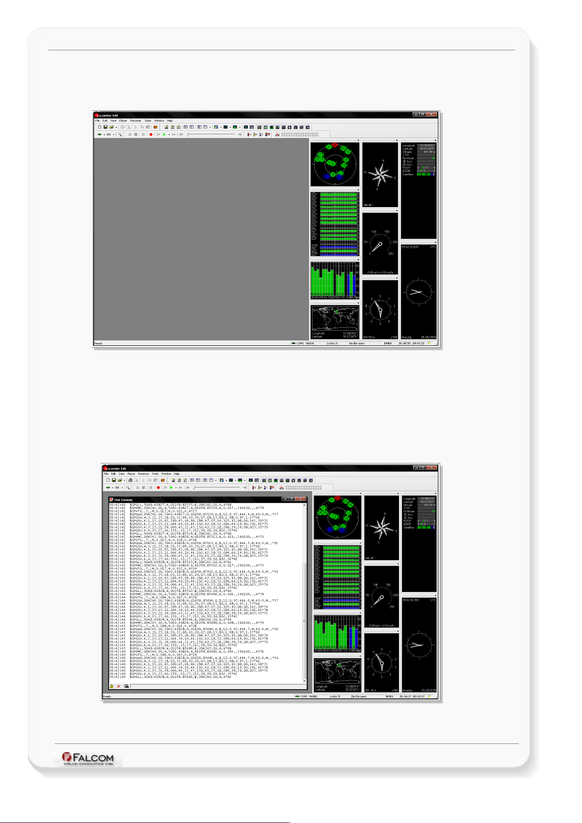
To show the UBX-INF or NMEA messages in textual form either press F8 or go to
the View menu and start "Text Console".
Figure 10 : UBX-INF or NMEA messages in textual form
This confidential document is a property of FALCOM and may not be copied or circulated without previous permission.
Page 12 of 13
Page 13

GETTING STARTED WITH FSA03-EVALKIT VERSION 1.0.1
The current tracking status of on-view satellites is represented by color. Table
below shows the color coding for graphical views.
COLOR DESCRIPTION
RED Satellite signal not available.
BLUE Satellite signal available, not available for use in navigation
CYAN Satellite signal available, available for use in navigation
GREE Satellite used in navigation.
To show the Deviation Map either press F12 or go to the View menu and start
"Deviation Map". The Deviation Map displays positions in longitude and latitude
relative to a defined reference position.
Figure 11 : Deviation Map
To perform a Coldstart, Warmstart, or Hotstart in the receiver, go to the
Receiver menu, "Action" and then start either Coldstart, Warmstart, or Hotstart.
ACTION DESCRIPTION
Coldstart Clears all data currently stored inside the FSA03 receiver including position, almanac,
Warmstart Same functionality as Hot Start except that it clears the ephemeris data and retains all other
Hotstart FSA03 receiver restarts with values stored inside the receiver. The stored ephemeris and
ephemeris.
data.
almanac are valid.
For more information about the u-Center software, refer to the manual "u-
Center_User_Guide(GPS-SW-08007).pdf " located in the "/..../u-blox" directory on your hard
drive when the software installation has finished.
This confidential document is a property of FALCOM and may not be copied or circulated without previous permission.
Page 13 of 13
 Loading...