

Page 1
THIS DOCUMENT IS AVAILABLE AT HTTP://WWW.FALCOM.DE/
.
DISCO-B4-GLONASS
Hardware manual
Version: 1.0.3; Modified: Tuesday 14 May 2013
Page 2

DISCO-B4-GLONASS HARDWARE MANUAL VERSION 1.0.3
Table of contents
1 INTRODUCTION.................................................................................5
1.1 General......................................................................................................................5
1.2 Circuit concept.........................................................................................................6
1.3 Related documents..................................................................................................7
2 SECURITY.......................................................................................8
2.1 General information.................................................................................................8
2.2 Exposure to RF energy............................................................................................8
2.3 Driving.......................................................................................................................8
2.4 Electronic devices....................................................................................................9
2.5 Vehicle electronic equipment.................................................................................9
2.6 Medical electronic equipment.................................................................................9
2.7 Aircraft.......................................................................................................................9
2.8 Children.....................................................................................................................9
2.9 Blasting areas...........................................................................................................9
2.10 Potentially explosive atmospheres......................................................................9
3 SAFETY STANDARDS.......................................................................10
4 TECHNICAL DATA...........................................................................11
4.1 Product features.....................................................................................................11
4.1.1 Power consumption............................................................................................12
4.1.2 Operating temperatures......................................................................................13
4.1.3 GSM/GPRS engine features..............................................................................14
4.1.4 Navigation features.............................................................................................15
4.2 NMEA data message..............................................................................................16
5 DISCO-B4-GLONASS APPLICATION INTERFACE..............................17
5.1 Power supply..........................................................................................................17
5.1.1 Power supply pins (1 and 2) on the 8-pin connector..........................................17
5.1.2 Automatic shutdown...........................................................................................17
5.1.3 Power saving......................................................................................................18
5.2 Determining the External Equipment Type.........................................................18
6 HARDWARE INTERFACES..................................................................19
6.1 8pin connector, pin assignments.........................................................................20
6.1.1 8-pin connector pinout........................................................................................20
6.1.2 Special pin description (Pins 4, 5, 6)..................................................................21
6.1.2.1 How to use them as analog inputs......................................................................................... 21
6.1.2.2 How to use these pins as digital Inputs (Pin 4, 5, 6)..............................................................23
6.1.2.3 How to use these pins as digital outputs (Pin 4, 5, 6)............................................................24
6.1.2.4 How to use IGN pin(pin 3)......................................................................................................25
6.1.2.5 Serial communication signals (RxA and TxA)........................................................................ 26
6.1.3 4pin row connector.............................................................................................26
6.2 Insert the SIM card holder inside the device.......................................................27
6.2.1 How to enter the SIM card PIN:..........................................................................29
This confidential document is a property of FALCOM and may not be copied or circulated without previous permission.
Page 2 of 36
Page 3
DISCO-B4-GLONASS HARDWARE MANUAL VERSION 1.0.3
6.3 Mounting.................................................................................................................29
6.4 Audio jacks.............................................................................................................30
6.4.1.1 Audio Interface ..................................................................................................................... 31
7 HOUSING.....................................................................................32
8 APPENDIX....................................................................................33
8.1 Schematics.............................................................................................................33
8.1.1 Installation guidance for 8-pin connector............................................................33
8.2 Setting up DISCO-B4-GLONASS-EVALKIT..........................................................34
8.3 What should be considered when using the DISCO-B4-GLONASS device.....35
Version history:
This table provides a summary of the document revisions.
Version
Author Changes Modified
1.0.3 F. Beqiri - Added "Hint:" - An annual replacement of the O'ring rubber recommended.
- Added chapter 6.2.1 - Procedure for greasing the O-ring.
14/05/2013
1.0.2 F. Beqiri - Added the part number of 8pin connector (Neltron 5560A-08) - Counter part (Neltron 5560T-08)
- Added the part number of 4pin connector (Neltron 5561A-04) - Counter part (Neltron 5560A-04)
- Updated chapter 8.1.1
04/09/2012
1.0.1 F. Beqiri - Changed device name from FOX-LT-IP-GLONASS to DISCO-B4-GLONASS 17/10/2011
1.0.0 F. Beqiri - Initial version. 31/03/2011
This confidential document is a property of FALCOM and may not be copied or circulated without previous permission.
Page 3 of 36
Page 4

DISCO-B4-GLONASS HARDWARE MANUAL VERSION 1.0.3
Cautions
Information furnished herein by FALCOM is believed to be accurate and reliable. However, no
responsibility is assumed for its use. Please, read carefully the safety precautions.
If you have any technical questions regarding this document or the product described in it, please
contact your vendor.
General information about FALCOM and its range of products are available at the following Internet
address: http://www.falcom.de/
Trademarks
Some mentioned products are registered trademarks of their respective companies.
Copyright
This document is copyrighted by FALCOM WIRELESS COMMUNICATIONS GmbH with all rights reserved. No
part of this documentation may be produced in any form without the prior written permission of FALCOM
WIRELESS COMMUNICATIONS GmbH.
FALCOM WIRELESS COMMUNICATIONS GmbH.
No patent liability is assumed with respect to the use of the information contained herein.
Note
Specifications and information given in this document are subject to change by FALCOM without
notice.
This confidential document is a property of FALCOM and may not be copied or circulated without previous permission.
Page 4 of 36
Page 5

DISCO-B4-GLONASS HARDWARE MANUAL VERSION 1.0.3
1 INTRODUCTION
This product manual is only addressed to qualified personnel which are well skilled in
electronical/electrical installation and not addressed to private consumers / end users. The
installation, implementing or setting into operation of the product can only be performed by
qualified personnel.
The status of the product described in the data sheet may have changed since publication of the
data sheet and therefore information in this data sheet on product status may be outdated. The
latest information of the product is available on the download area of the FALCOM website.
1.1 General
FALCOM is providing all kinds of GPS and telematics products as required by the market today.
DISCO-B4-GLONASS unit is a new vehicle tracking system combining GPS and GLONASS positioning
systems with a higher level of reliability for complete telematics functionality. It is a free
configurable smart tracking device which can be fully adapted to user requirements. Using a QuadBand GSM/GPRS technology for two way worldwide communication, the ability to work with
global navigation satellite systems (GNSS) - GPS and GLONASS, a high-capacity Li-Polymer
rechargeable backup-battery, and housed in a weatherproof plastic case, the device is suitable for
a wide range of mixed indoor/outdoor applications in the AVL, fleet management, Asset tracking,
vehicle security and recovery and transit sectors. The device has a protection class IP69K, which
allows mounting of the device permanently on the roof of the vehicles, including buses, trucks,
trains, vessels and other assets. The DISCO-B4-GLONASS device comprises an embedded
configurable software that provides even greater performance and flexibility for its users and
system integrators to develop high-performance applications that allow vehicle tracking via SMS
and over the Internet. The configuration of the DISCO-B4-GLONASS can be done via local serial link
or remotely via SMS or over the Internet. The tracking functionality of the embedded mobile client
application is combined with a variety of alert messaging capabilities. The configurable alert
messages may contain current position, device status and the state of the inputs/outputs lines. In
addition to that two predefined digital inputs are detecting ignition line status and main power (car
battery) failure, so you may handle these events and use as notification.
The embedded software can be controlled by word like “PFAL” commands needed for executing
particular actions, reading or setting particular configurations. These commands are valid for all
kinds of operation channels including Serial, SMS, CSD, TCP and SMTP.
DISCO-B4-GLONASS provides Geofence features for territory management, route verification,
prohibited locations, parking area and more, with exception reporting to a wide variety of events
such as arrivals, departures, deliveries, pick-ups, illegal entries, unauthorized movement, etc.
DISCO-B4-GLONASS contains a data-logger (history feature) that enables you to archive unique
vehicle locations in sequence for up to 45 days for later analysis and evaluation (for example,
archive interval up to 20 sec.).
The physical interface to the device application is made through an integrated 8pin connector. It is
required for controlling the device, receiving GPS location data, transferring data and providing
automotive power supply lines. This connector provides 1 serial interface giving you maximum
flexibility for local use. A separate 4pin double row connector (containing RX, TX, GND and VOUT) is
for connecting a MFD device and two separate audio jacks for directly connecting an active speaker
and a microphone.
This confidential document is a property of FALCOM and may not be copied or circulated without previous permission.
Page 5 of 36
Page 6

DISCO-B4-GLONASS HARDWARE MANUAL VERSION 1.0.3
DISCO-B4-GLONASS is a device that can be configured and integrated onto any asset platform, including:
- Trailers,
- Trucks,
- Delivery vans,
- Ships,
- Trains,
- Rail cars,
- as well as other industrial monitoring solutions.
and it can be used in a variety of applications, including:
• Real time online tracking,
• Asset Tracking,
• Fleet management / monitoring,
• Security / emergency services,
• Real time satellite navigation,
• Territory management,
• Personalized drivers logbook,
• Route verification,
• Trip management / distance calculations,
• Theft protection,
• Toll collection,
• Pay as you drive.
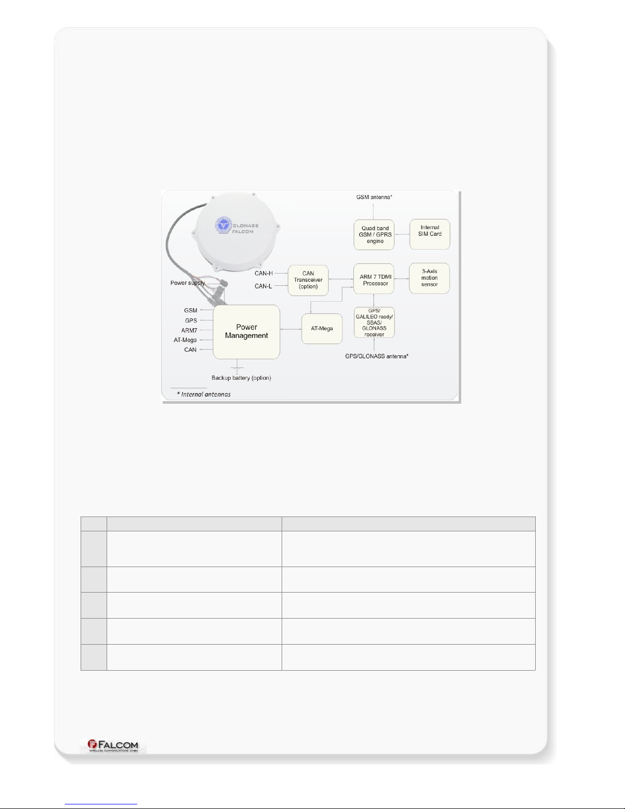
1.2 Circuit concept
DISCO-B4-GLONASS architecture consists of the following major components (a block diagram is
available below):
HARDWARE ARCHITECTURE:
High-performance Quad-Band GSM/GPRS core,
Combined GPS/GALILEO ready/GLONASS/SBAS receiver for precise positioning,
ARM7TDMI Processor controlling all functions of the system,
Internal GSM antenna,
Internal GPS/GLONASS antenna.
ADDITIONAL OPTIONS TO DISCO-B4-GLONASS
3D motion sensor,
Rechargeable Li-Polymer battery (see Ordering Guide).
CAN-BUS interface
This confidential document is a property of FALCOM and may not be copied or circulated without previous permission.
Page 6 of 36
Page 7
DISCO-B4-GLONASS HARDWARE MANUAL VERSION 1.0.3
PHYSICAL INTERFACES:
8pin double row connector
Power supply lines,
3 x Multi-line I/Os,
1 x Ignition,
RS232 port (Rx, Tx, GND),
Audio jacks for voice call (1 x Microphone; 1 x Speaker),
Figure 1: DISCO-B4-GLONASS block diagram
1.3 Related documents
Some other PDF documents such as FCC approval, application notes, Certificate of Conformity
R&TTE etc. are also available on the Web at: http://www.falcom.de/ in the published download
area. In addition to this document, the following files comprise the full set of FALCOM DISCO-B4-
GLONASS product manuals:
NR PDF file name Description
[1] AVL_PFAL_Configuration_Command_Set.pdf Contains the description of the internal firmware and the supported
Configuration Command Set for the FALCOM STEPPIII, FOX/-LT/-EN/-IN,
DISCO and BOLERO-LT.
[2] AppNotes_Transform_history_data.pdf Contains information of how to transform history data that is being
transmitted from a FALCOM AVL device via TCP connection.
[3] AppNote_Remote_update.pdf Contains information of how to upgrade FALCOM AVL devices to a new
firmware revision remotely via TCP (server based application).
[4] STEPPIII_FOX_BOLERO_LT_Software_Update.pdf Contains information how to upgrade a FALCOM AVL device to a new
firmware version locally via serial port.
[5] AppNotesRemoteUpdateWithWorkbench.pdf Contains information how to upgrade a FALCOM AVL devices to a new
firmware version remotely via TCP.
These PDF files are viewable and printable from Adobe Reader. If you do not have the Adobe Reader installed, you can
download it from http://www.adobe.com.
This confidential document is a property of FALCOM and may not be copied or circulated without previous permission.
Page 7 of 36
Page 8

DISCO-B4-GLONASS HARDWARE MANUAL VERSION 1.0.3
2 SECURITY
IMPORTANT FOR THE EFFICIENT AND SAFE OPERATION OF YOUR GSM-MODEM, READ THIS
INFORMATION BEFORE USE!
Your cellular engine DISCO-B4-GLONASS is one of the most exciting and innovative electronic
products ever developed. With it you can stay in contact with your office, your home, emergency
services and others, wherever service is provided.
This chapter contains important information for the safe and reliable use of the DISCO-B4-
GLONASS device. Please read this chapter carefully before starting to use the cellular engine
DISCO-B4-GLONASS.
2.1 General information
Your DISCO-B4-GLONASS device utilizes the GSM/GPS standard for cellular technology. GSM is a
newer radio frequency („RF“) technology than the current FM technology that has been used for
radio communications for decades. The GSM standard has been established for use in the
European community and elsewhere. Your DISCO-B4-GLONASS is actually a low power radio
transmitter and receiver. It sends out and receives radio frequency energy. When you use your
modem, the cellular system handling your calls controls both the radio frequency and the power
level of your cellular modem.
SIM cards are needed for the use of the acquired devices, which are not included in the scope of
delivery of the device. The SIM cards can be acquired e.g. by specific providers. Additional costs can
result from the use of the SIM cards which are to be borne by the purchaser (client) of the devices.
The seller does not cover the extra costs for the use of the devices. The seller gives no
recommendation for the use of specific SIM cards and is not liable for the fact that the devices are
usable with all available SIM cards. The seller is also not liable for any other costs that are needed
for the application of the customer in connection with this device.
2.2 Exposure to RF energy
There has been some public concern about possible health effects when using GSM modems.
Although research on health effects from RF energy has focused for many years on the current RF
technology, scientists have begun research regarding newer radio technologies, such as GSM. After
existing research had been reviewed, and after compliance to all applicable safety standards had
been tested, it has been concluded that the product is fit for use.
If you are concerned about exposure to RF energy, there are things you can do to minimize
exposure. Obviously, limiting the duration of your calls will reduce your exposure to RF energy. In
addition, you can reduce RF exposure by operating your cellular modem efficiently by following the
guidelines below.
2.3 Driving
Check the laws and regulations on the use of cellular devices in the area where you drive. Always
obey them. Also, when using your DISCO-B4-GLONASS while driving, please pay full attention to
driving, pull off the road and park before making or answering a call if driving conditions so require.
When applications are prepared for mobile use, they should fulfil road-safety instructions of the
current law!
This confidential document is a property of FALCOM and may not be copied or circulated without previous permission.
Page 8 of 36
Page 9

DISCO-B4-GLONASS HARDWARE MANUAL VERSION 1.0.3
2.4 Electronic devices
Most electronic equipment, for example in hospitals and motor vehicles is shielded from RF
energy. However, RF energy may affect some malfunctioning or improperly shielded electronic
equipment.
2.5 Vehicle electronic equipment
Check your vehicle manufacturer’s representative to determine if any on board electronic
equipment is adequately shielded from RF energy.
2.6 Medical electronic equipment
Consult the manufacturer of any personal medical devices (such as pacemakers, hearing aids, etc.)
to determine if they are adequately shielded from external RF energy.
Turn your DISCO-B4-GLONASS device OFF in health care facilities when any regulations posted in
the area instruct you to do so. Hospitals or health care facilities may be using RF monitoring
equipment.
2.7 Aircraft
Turn your DISCO-B4-GLONASS OFF before boarding any aircraft. Use it on the ground only with
crew permission. Do not use it in the air. To prevent possible interference with aircraft systems,
Federal Aviation Administration (FAA) regulations require you to have permission from a crewmember to use your modem while the plane is on the ground. To prevent interference with cellular
systems, local RF regulations prohibit using your modem whilst airborne.
2.8 Children
Do not allow children to play with your DISCO-B4-GLONASS device. It is not a toy. Children could
hurt themselves or others (by poking themselves or others in the eye with the antenna, for
example). Children could damage the modem or make calls that increase your modem bills.
2.9 Blasting areas
To avoid interfering with blasting operations, turn your device OFF when in a “blasting area” or in
areas posted: „turn off two-way radio“. Construction crew often uses remote control RF devices to
set off explosives.
2.10 Potentially explosive atmospheres
Turn your DISCO-B4-GLONASS device OFF when in any area with a potentially explosive
atmosphere. It is rare, but your modems or their accessories could generate sparks. Sparks in such
areas could cause an explosion or fire resulting in bodily injury or even death. Areas with a
potentially explosive atmosphere are often, but not always, clearly marked. They include fuelling
areas such as petrol stations; below decks on boats; fuel or chemical transfer or storage facilities;
and areas where the air contains chemicals or particles, such as grain, dust or metal powders. Do
not transport or store flammable gas, liquid or explosives, in the compartment of your vehicle,
which contains your modem or accessories.
Before using your modem in a vehicle powered by liquefied petroleum gas (such as propane or
butane) ensure that the vehicle complies with the relevant fire and safety regulations of the
country in which the vehicle is to be used.
This confidential document is a property of FALCOM and may not be copied or circulated without previous permission.
Page 9 of 36
Page 10

DISCO-B4-GLONASS HARDWARE MANUAL VERSION 1.0.3
3 SAFETY STANDARDS
Your GSM/GPRS/GPS device complies with all applicable RF safety standards.
DISCO-B4-GLONASS meets the safety standards for RF receivers and the standards and
recommendations for the protection of public exposure to RF electromagnetic energy established
by government bodies and professional organizations, such as directives of the European
Community, Directorate General V in matters of radio frequency electromagnetic energy.
This confidential document is a property of FALCOM and may not be copied or circulated without previous permission.
Page 10 of 36
Page 11

DISCO-B4-GLONASS HARDWARE MANUAL VERSION 1.0.3
4 TECHNICAL DATA
4.1 Product features
Supply voltage range:
➢ Operating power supply voltage range of +10.8 V to +32.0 V,
suitable for direct connection to an automotive +12V or +24V DC
power source (car battery).
Power saving:
➢ 7 different energy-saving modes - programmable with PFAL
commands. Refer to the chapter 5.1.3, "Power saving" for a brief
overview.
Operating temperature range:
➢ - 40°C to + 85°C (see chapter 4.1.2 for more details)
Physical characteristics:
➢ Size: Ø 187.2 ± 0.1 mm; ↕ 47.2 ± 0.1 mm
➢ Weight (without options): ca. 468 gr.
Physical Interfaces:
➢ 8-pin single row connector (Neltron 5560A-08):
✔ 3 x I/Os multi functional (each pin has dual functions as analog or
digital - software configurable. Each digital pin can operate either
as an input or output - depending on the external user-circuit),
✔ 1 x Ignition (software controlled feature),
✔ 1 x Power supply (software controlled feature)
✔ 1 x Serial port (Rx, Tx), Baud rate is controlled by firmware
4800...115200 bps (default=57600 bps), 8 data bits, no parity, 1
stop bit, no flow control,
➢ 4-pin single row connector (Neltron 5561A-04):
✔ 1 x Power (output voltage for external devices such as MFD1)
✔ 1 x Serial port (Rx, Tx 3.3V levels), Baud rate is controlled by
firmware 4800...115200 bps (default=57600 bps), 8 data bits, no
parity, 1 stop bit, no flow control,
➢ Audio jacks:
✔ 1 x Microphone (2.5mm jack),
✔ 1 x Speaker (3.5mm jack),
➢ Internal SIM Card holder (supports 1.8/3 V SIM cards) - SIM card
should be inserted by skilled personnel.
Housing:
➢ PA6 Plastic.
➢ Protection class: IP69K
This confidential document is a property of FALCOM and may not be copied or circulated without previous permission.
Page 11 of 36
Page 12

DISCO-B4-GLONASS HARDWARE MANUAL VERSION 1.0.3
Directive:
➢ RoHS compliant.
Firmware:
➢ Embedded TCP/IP stack, including TCP, IP and SMTP protocols,
➢ Accessible via PFAL commands,
➢ Upgradable locally via serial port and remotely over the air
(GPRS/TCP).
Internal memory:
➢ 8 Mbyte FLASH for configuration, data-logging and firmware storage,
➢ 2 MByte RAM.
Evaluation board:
➢ To evaluate with DISCO-B4-GLONASS you need a FOX evaluation
board which is included in the DISCO-B4-GLONASS EVALKIT (see
chapter 8.2).
Supported protocols:
➢ NMEA Msg.: GLL, GGA, RMC, VTG, GSV, GSA
FALCOM Msg.: IOP, GSM, AREA, 3DP, BIN - see related
documents [1] and Table 3.
4.1.1 Power consumption
All measurements have been performed: DCS 1800 MHz, Power Level 10, Cell Power -75dBm, T
amb
=
23°C, V
IN+
= 12 V DC and 4.2 V DC (battery powered).
Modes Average power
consumption (mA) @ +12 V
Average power
consumption (mA) @ +4.2 V
Comments
GPS off / GSM off
GPS on / GSM off
GPS off / GSM on
GPS on / GSM on
58 85 Microcontroller remains on
85 144 with valid GPS-fix
70 112 GSM idle (registered) and GPSR detached
100 170
GPRS is attached and TCP-connected.
Device sends a TCP packet every 30 sec.
Note: These values may vary over time and environments condition can not be guaranteed.
Table 1: Power supply and current consumption at 12 VDC
Average current consumption in sleep mode
Sleep Modes @ 12 V (external power) @ 4 V (battery power) Unit
IGN 840 260 µA
IGN+Motion 1230 810 µA
IGN+Ring 17 22 mA
IGN+Timer 920 330 µA
Note: These values may vary over time and environments condition can not be guaranteed.
Table 1.1: Power supply and current consumption for different sleep modes.
This confidential document is a property of FALCOM and may not be copied or circulated without previous permission.
Page 12 of 36
Page 13

DISCO-B4-GLONASS HARDWARE MANUAL VERSION 1.0.3
4.1.2 Operating temperatures
Parameter Min. Typ. Max. Unit
Storage temperature (without internal battery) -40 +25 +90 °C
Storage temperature (with internal battery) -20 +25 +60 °C
Operating temperature* (without internal battery) -40 +25 +85 °C
Charging temperature 0 +25 +45 °C
Discharging temperature -20 +25 +60 °C
* The GSM/GPRS module is fully functional (-20 °C to + 55 °C meets the 3GPP specifications)
Table 2: Operating temperature
This confidential document is a property of FALCOM and may not be copied or circulated without previous permission.
Page 13 of 36
Page 14

DISCO-B4-GLONASS HARDWARE MANUAL VERSION 1.0.3
4.1.3 GSM/GPRS engine features
GSM/GPRS core:
➢ Quad-Band GSM/GPRS module
➢ Quad-Band: GSM 850, 900, DCS 1800, PCS 1900.
➢ Compliant to GSM Phase 2/2+
Output power:
➢ Class 4 (2 W) at EGSM900/850
➢ Class 1 (1 W) at GSM1800 and GSM 1900
GPRS connectivity:
➢ GPRS multi-slot class 10
➢ GPRS mobile station class B
DATA:
GPRS
➢ GPRS data downlink transfer: max. 85.6 kbps (see table 2).
➢ GPRS data uplink transfer: max. 42.8 kbps (see table 2).
➢ Coding scheme: CS-1, CS-2, CS-3 and CS-4.
CSD
➢ CSD transmission rates: 2.4, 4.8, 9.6, 14.4 kbps, non-transparent,
V.110.
SMS:
➢ Text mode.
Ring tones:
➢ Offers a choice of 30 different ringing tones, easily selectable with
PFAL commands.
GPRS Coding scheme:
Coding scheme 1 Timeslot 2 Timeslots 4 Timeslots
CS-1: 9.05 kbps 18.1 kbps 36.2 kbps
CS-2: 13.4 kbps 26.8 kbps 53.6 kbps
CS-3: 15.6 kbps 31.2 kbps 62.4 kbps
CS-4: 21.4 kbps 42.8 kbps 85.6 kbps
Table 2: Coding schemes and maximum net data rates over air interface
Please note that, the values listed above are the maximum ratings which, in practice, are influenced by a great
variety of factors, primarily, for example, traffic variations and network coverage.
This confidential document is a property of FALCOM and may not be copied or circulated without previous permission.
Page 14 of 36
Page 15

DISCO-B4-GLONASS HARDWARE MANUAL VERSION 1.0.3
4.1.4 Navigation features
GPS/GLONASS/GALILEO ready/SBAS engine:
➢ Number of channels: 32
➢ GPS/GALILEO ready/SBAS: L1 1575.42 MHz
➢ GLONASS: L1 1597.5 - 1609.5 MHz
Accuracy:
➢ horizontal
✔ autonomous mode 2.5 m
✔ differencial mode 1 m
➢ height 3 m
➢ velocities 0.05 m/s
Time to First Fix (TTFF):
➢ Hot starts < 3 s
➢ Cold starts 30 s
Sensitivity:
➢ Tracking -160 dBm
➢ Acquisition -143 dBm
Dynamic Conditions:
➢ Velocity 500 m/s.
➢ Acceleration 5 g
➢ Altitude 18 000 m
➢ Max. update rate 1 Hz
This confidential document is a property of FALCOM and may not be copied or circulated without previous permission.
Page 15 of 36
Page 16

DISCO-B4-GLONASS HARDWARE MANUAL VERSION 1.0.3
4.2 NMEA data message
DISCO-B4-GLONASS delivers data in the NMEA-0183 format. Table below lists the NMEA and
FALCOM output messages supported by the DISCO-B4-GLONASS device and gives a brief
description for each protocol. For further description about these protocols, refer to the related
documents [1].
The running firmware inside the device offers the possibility to switch on and off each protocol
that is listed in the table below. As mentioned above the firmware inside the device supports a lot
of PFAL commands enabling full control of the device. There are also PFAL commands which allow
sending of these protocols via SMS, TCP, Data call and e-mail. For example, the PFAL commands
"PFAL,GSM.SMS.Send..." and "PFAL,TCP.Client.Send..." allow you to send an SMS message to a
user or a TCP packet to a TCP server to let him know the current location, GPS state, UTC time,
Date, Speed and Course over ground of the device. The received SMS contents or TCP packet can
be forwarded to a map software for locating the device graphically on it. When you install such a
device in a vehicle, you are able to have always full control of the vehicle. In this way you will know
where your vehicle is, what is happening with your vehicle, has your vehicle been moved without
authorization from a park area, real time vehicle movements and more. The TCP server developed
by FALCOM called "Trace4You" has a lot of such features allowing you to have full control of your
vehicle, fleet and other assets.
NMEA Description
GGA Time, position and fix type data.
GLL Latitude, longitude, UTC time of position fix and status.
GSA GPS receiver operating mode, satellites used in the position solution and DOP values.
VTG The direction and the ground speed
GSV The number of GPS satellites in view, satellite ID numbers, elevation, azimuth and SNR values.
RMC Time, date, position, course and speed data.
FALCOM Description
IOP The status of the digital/analog inputs and output ports and battery voltage (if battery available)
GSM The GSM operator, reception, registration status, GSM field strength, area code and cell ID.
AREA The state (entered / remaining) of 32 areas/geofences - such as territory management, route verification,
prohibited locations, parking area and more.
3DP The state of the Motion Sensor (hardware option)
BIN User protocol including time, date, position, course and speed data in binary format (small sized - only 21
characters).
Table 3: NMEA Output Messages
This confidential document is a property of FALCOM and may not be copied or circulated without previous permission.
Page 16 of 36
Page 17

DISCO-B4-GLONASS HARDWARE MANUAL VERSION 1.0.3
5 DISCO-B4-GLONASS APPLICATION INTERFACE
5.1 Power supply
The power supply for the DISCO-B4-GLONASS unit has to be a single voltage source of V
+IN
= +10.8
V...+32.0 VDC. The operating voltage (V+IN) has to be permanently applied to the DISCO-B4-
GLONASS unit and able to provide sufficient current of up to 1.9 A.
The operating voltage (V
+IN
and GND) is protected against voltage spikes and reverse polarity, but not
against continuous-overvoltage.
NOTE: Operating voltage range must never be exceeded; care must be taken in order to fulfill
min/max voltage requirements.
5.1.1 Power supply pins (1 and 2) on the 8-pin connector
One +IN pin on the 8-pin double row connector is dedicated to connect the supply voltage, and the
GND pin for grounding.
Both +IN and GND pins serve for powering the DISCO-B4-GLONASS device and charging the
internal Li-Polymer battery if available (option). DISCO-B4-GLONASS has an automatic power
ON-function when external power is applied. The power supply for the DISCO-B4-GLONASS is
capable of utilizing current ranging from V
+IN
=+10.8 V... +32.0 VDC designed for automotive
application.
Signal name I/O Parameter Description
+IN I +10.8 V...+32.0 VDC. The
operating voltage must never be
exceeded.
Positive operating voltage.
For security reason, it is recommended to integrate externally
a 2A fuse link between interconnection plug (8-pin connector)
and d.c.-power source (see Fig. 16).
GND - 0 V Ground
5.1.2 Automatic shutdown
Automatic shutdown takes effect if:
• battery voltage level runs low and external power supply is disconnected.
• supply voltage is below the specified input voltage range and internal battery is
disabled.
This confidential document is a property of FALCOM and may not be copied or circulated without previous permission.
Page 17 of 36
Page 18

DISCO-B4-GLONASS HARDWARE MANUAL VERSION 1.0.3
5.1.3 Power saving
SLEEP mode reduces the functionality of the modules of the DISCO-B4-GLONASS device to a
minimum and thus minimizes the current consumption to the lowest level. Settings for activating
one of the supported low power modes can be made using the $PFAL,Sys.Device.Sleep command.
For details, see example in table below.
Following SLEEP modes are supported by the DISCO-B4-GLONASS device:
Modes Description
IGN
Device goes to sleep and wakes up when IGN (pin 3 - blue color) changes its digital level from
Low to High (performs a rising edge).
Ring
Device goes to sleep and wakes up when the GSM module receives a voice call or an SMS.
Timer=1:20:00
Device goes to sleep and wakes up after the defined time has expired.
Motion=5,20,20
Device goes to sleep and wakes up when motion is detected.
ExtPwrDetect
Device goes to sleep and wakes up when external power (higher than 9 V) is connected to the
device.
ExtPwrDrop
Device goes to sleep and wakes up when external power is disconnected or it drops below 8 V.
AiWu=5.1,12
Device goes to sleep and wakes up when the voltage on I/O1 (pin 4 used as analog input)
exceeds the defined upper or lower threshold.
Example $PFAL,Sys.Device.Sleep=IGN+Ring+Timer=1:20:00
IMPORTANT: The sleep and wake-up procedures are quite different depending on the selected
sleep mode. Please keep in mind that the power saving with "Ring" parameter
works properly only when PIN authentication has been done and the device is
already registered in the GSM network. If you attempt to activate power saving
while the device is not registered in the GSM network, the SIM card is not inserted
or the PIN not correctly entered, the device responds with an error "ring shutdown
aborted due to bad GSM coverage" and the power saving does not take place. For
more details, refer to the manual "steppIII_FOX-
LT_bolero_lt_PFAL_Configuration_Command_Set.pdf".
NOTE (This note is related to the battery-powered devices only): The internal battery of the DISCO-
B4-GLONASS must have enough power to safely wake up the device from a sleep mode. If the
internal battery of the DISCO-B4-GLONASS device does not have enough power, the device
cannot complete the wake up operation.
5.2 Determining the External Equipment Type
Before you connect the serial port pins on the aforementioned terminals (DCE units) to external
equipment, you need to determine if the external hardware serial ports are configured as DTE or
DCE.
DISCO-B4-GLONASS is designed for use as a DCE device. Based on the aforementioned conventions
for DCE-DTE connections, it communicates with the customer application (DTE) using the following
signals:
DISCO-B4-GLONASS Terminal (DCE) to Application (DTE)
RxA <---------- TXD
TxA ----------> RXD
Table 4: The signalling definitions between DTE and DCE.
This confidential document is a property of FALCOM and may not be copied or circulated without previous permission.
Page 18 of 36
Page 19

DISCO-B4-GLONASS HARDWARE MANUAL VERSION 1.0.3
6 HARDWARE INTERFACES
This chapter describes the hardware interfaces:
• 8pin single row connector (Neltron 5560A-08)
• Mounting holes
• Audio jacks (3.5mm and 2.5mm audio jacks)
• 4pin single row connector (Neltron 5561A-04)
Interface specifications
8pin single row connector Eight-wire cable with an 8-pin connector (Neltron 5560A-08) on the end and 1
meter cable length. It consists of IN/OUT, power supply line and RX/TX.
Audio jacks 3.5mm and 2.5mm audio jacks. The 3.5mm jack is where you plug in a speaker.
The 2.5mm jack is where you plug in a microphone.
Mounting holes 6 holes for attaching it to a suitable location (use M4x30 self tapping or machine
screws, not included).
Fastening screw holes 12 x holes for fastening both cases together.
4pin single row connector Four-wire cable with an 4-pin connector (Neltron 5561A-04) on the end and 1
meter cable length for connecting a MFD device to the DISCO-B4-GLONASS.
Table 5: Interface specifications
Figure 2: Interface specifications
This confidential document is a property of FALCOM and may not be copied or circulated without previous permission.
Page 19 of 36
Page 20

DISCO-B4-GLONASS HARDWARE MANUAL VERSION 1.0.3
6.1 8pin connector, pin assignments (Neltron 5560A-08)
Figure 3: Pin assignments of the 8-pin connector.
6.1.1 8-pin connector pinout
PIN NAME COLOR DIRECTION DISCRIPTION LEVEL
1 +IN Red Input
Power supply input. The power supply must be able to
meet the requirements of current consumption. Care
must be taken so that the operating voltage applied to
the terminal stays within the voltage range. Applying a
voltage outside of the voltage range can damage the
module. For security reason, it is recommended to
integrate externally a 2A fuse link between power
source and DISCO-B4-GLONASS.
V
+IN
= + 10.8 ... + 32.0 V
Imax ≤ 2A
2 GND Braun - Ground. 0 V
3 IGN Blue Input
General purpose input. Either connect it to the vehicle
ignition and use it for journey START and STOP reports
or connect it to the operating voltage +IN and with the
help of an external switch you wakeup the DISCO-B4GLONASS device from IGN-Sleep mode (awaking from
this mode requires a HIGH signal). See also chapter
6.1.2.4.
HIGH ≥+10.8 .. +32.0 V DC;
LOW = 0V
4 I/O1 Orange
5
I/O2 or
CAN_L
Yellow
6
I/O3 or
CAN_H
Green
Input/Output
Software configurable pins. Each pin has dual functions
as analog or digital. Each digital pin can be individually
set to operate either as input or output.
OUT: 100 mA max. @ +0 ..
+32.0V DC
IN: 0 V..+32.0V DC
(High & Low levels are free-
programmable)
Analog : Up to 32.0 V DC/10
bits resolution
7 RxA Purple Input
Serial port (receive data) for direct connection to the
host PC (configuration, evaluation, firmware). If not
used leave open.
V24, ±12 V
8 TxA Black Output
Serial port (transmit data) for direct connection to the
host PC (transmitting history data, output GPS protocols
and others). If not used leave open.
V24, ±12 V
Table 6: Description of the 8-pin double-row connector
This confidential document is a property of FALCOM and may not be copied or circulated without previous permission.
Page 20 of 36
Page 21

DISCO-B4-GLONASS HARDWARE MANUAL VERSION 1.0.3
6.1.2 Special pin description (Pins 4, 5, 6)
These pins have dual functions. All of them are controlled by the internal firmware of DISCO-B4GLONASS. Therefore, the user must specify whether they will be as analog or digital pins.
This function is controlled by the command PFAL,IO0[1,2].Config. If, for example, you want to use I/O1
as an analog pin, and the I/O2 and I/O3 as digital, the command settings would look like this:
PFAL,IO0.Config=AI,2,11 //0 = I/O1; AI = analog; 2 and 11 = min. and max.
voltages for Low and High events.
PFAL,IO1.Config=DI,5,10 //1 = I/O2; DI = digital; 5 and 10 = min. and max. voltages
for Low and High events
If a pin from I/O1 to I/O3 is configured as a digital pin, then the pin must be assigned as an input or an
output. If you want I/O2 to be an input and I/O3 to be an output, the command settings would look like
the following:
PFAL,IO1.Config=DI,5,10 //1 = I/O2; DI = digital; 5 and 10 = min.
and max. voltages for Low and High
events.
PFAL,IO6.Set=high[low,hpulse,lpulse,cyclic] //6 = I/O3; high = sets output to high.
Some examples how to use them are given in sections below.
When using an I/O as digital you must set it to high first (with PFAL command
“$PFAL,IO4[5,6].Set=high”), otherwise 0V will be measured (and the device could be damaged).
6.1.2.1 How to use them as analog inputs
Because these pins can operate either as digital or analog, they have to be configured and calibrated
with PFAL commands before using them.
Analog voltages of up to 32.0V with a 10 bits resolution can be processed and remotely evaluated by a
server application. A pull-up resistor to a constant input voltage allows for resistive transducers to
ground, e.g. fuel sensor or thermistors.
To use these IOs as analog, the following command should be set to the device.
PFAL,IO0[1,2].Config=AI,2,11
where 0, 1 and 2 are indices corresponding to IO1 (pin 4), IO2 (pin 5) and IO3 (pin 6) respectively.
While the value 2 and 11 are min. and max. voltages that will be used to generate Low and High
events, respectively.
Detailed information can be found in software manual “steppIII_FOXLT_bolero_lt_PFAL_Configuration_Command_Set.pdf“.
Connection example 1 (for I/O1 and I/O2):
An analog input can be connected to a temperature sensor (a NTC resistor for instance). In the
diagram below is used a fixed resistor is used from the input voltage to the I/O 2, and a variable
resistor (Negative Temperature Coefficient - whose resistance or capacitance decreases when
temperature increases) to ground. It is possible to set a low temperature alarm and a high
temperature alarm. Passage through these thresholds will trigger an alarm. We recommend to
use SMS or TCP as alarm type with GPIOP protocol. The SMS can be received on a mobile phone,
modem or any GSM device when changes are detected. The analog-to-digital converter (ADC)
inside the unit has an input voltage range from 0 to 2.5 V. An application example is shown in
figure below:
This confidential document is a property of FALCOM and may not be copied or circulated without previous permission.
Page 21 of 36
Page 22

DISCO-B4-GLONASS HARDWARE MANUAL VERSION 1.0.3
Figure 4: An example block diagram of I/O2 when used as analog input.
Connection example 2 (for I/O1 and I/O2):
An analog input can be connected to a tachometer generator. The maximum output
voltage of the tachometer should be + 32.0 V (see illustrated example in figure below).
Both circuit examples (the NTC diagram above and the Tachometer below) are only illustrations to show
the aim of these I/Os when used as analog inputs.
Figure 5: An example block diagram of I/O1 when used as analog input.
This confidential document is a property of FALCOM and may not be copied or circulated without previous permission.
Page 22 of 36
Page 23

DISCO-B4-GLONASS HARDWARE MANUAL VERSION 1.0.3
6.1.2.2 How to use these pins as digital Inputs (Pin 4, 5, 6)
These pins are high active when used as digital inputs, so you can set V
IN(LOW)
and V
IN(HIGH)
to any levels
within the range from +0 to +32.0 VDC. The High and Low levels can be set with PFAL command (e.g.
PFAL,IO0[1,2].Config=DI,5,10) - where 0, 1 and 2 are indices corresponding to IO1 (pin 4), IO2 (pin 5)
and IO3 (pin 6) respectively. While the values 5 and 10 are min. and max. voltages that will be used to
generate Low and High events respectively. Detailed information can be found in software manual
“steppIII_FOX-LT_bolero_lt_PFAL_Configuration_Command_Set.pdf“.
The figure below illustrates how these inputs can be used in practice. When the internal software
detects input changes from High to Low or vice versa, a Falling or Rising edge Event is respectively
generated. Therefore, depending on the alarm type, the DISCO-B4-GLONASS can react to the input
changes and release different alarms such as sending out an SMS, email message, TCP packet, opening a
CSD connection or activating an output port. The alarm type is user-dependant.
Figure 6: An example block diagram of I/O1 when using it as digital input
A completed circuit example for all inputs is attached in section 8.1.1.
This confidential document is a property of FALCOM and may not be copied or circulated without previous permission.
Page 23 of 36
Page 24

DISCO-B4-GLONASS HARDWARE MANUAL VERSION 1.0.3
6.1.2.3 How to use these pins as digital outputs (Pin 4, 5, 6)
The DISCO-B4-GLONASS device supports three IOs which can be used either as input or output.
These outputs are open collectors. They can be directly connected via resistors (R) to LEDs, Relays
etc., which need no more than 100 mA @ up to + 32.0 V DC. The figures below show the schematic
of possible output connections. To use and activate these outputs use the command
$PFAL,IO4[5,6].Set=high[low,hpulse,lpulse, cyclic] for IO1, IO2 and IO3 respectively or you can
configure one or more alarms that activate these outputs when specific events occur (e.g.
$PFAL,Cnf.Set,AL0=IO.e8=redge: IO4.Set=cyclic,1000,2000).
In order to evaluate this alarm, first send this configuration to the DISCO-B4-GLONASS device and
then trigger IGN-pin to High – as result the IO1 goes High for 1 sec and Low for 2 sec. To set input 1
(IO1) to Low, just execute the command PFAL,IO4.Set=Low. For more details how to activate an
output and how to configure an alarm, refer to the manual “ steppIII_FOXLT_bolero_lt_PFAL_Configuration_Command_Set.pdf“. Both figures below show the schematic
connections of how to use this output. Please note: do not apply power directly to an output pin
without having a device (e.g. a resistor) between the output pin and external power.
Figure 7: An example block diagram of I/O1 when used to control an Relay.
Figure 8: An example block diagram of I/O3 when used to control an LED.
This confidential document is a property of FALCOM and may not be copied or circulated without previous permission.
Page 24 of 36
Page 25

DISCO-B4-GLONASS HARDWARE MANUAL VERSION 1.0.3
6.1.2.4 How to use IGN pin(pin 3)
The IGN-pin has two functions:
✔ It wakes up the system DISCO-B4-GLONASS from the IGN-sleep mode (when sleeping),
✔ and can be used to monitor the vehicle ignition state, to report/store the START and
STOP of a trip by using the events IO.e8=redge and IO.e8=fedge for START and STOP
respectively.
IGN-sleep mode is one of the eight supported energy-saving modes of operation in which all
unnecessary components are shut down. Once the device is awakened by IGN high signal, it returns
to full functionality.
Note that, the DISCO-B4-GLONASS device powers on automatically when external power is applied,
and IGN pin provides an additional “wake up” function for the IGN-sleep mode when it is
requested.
Using IGN pin you can configure the system to store a specific location or to deliver an alarm SMS
or TCP packet if an unauthorised entry to start your vehicle is attempted. In such a case use the
IGN generated event as a condition to start vehicle tracking.
NOTE: All battery powered DISCO-B4-GLONASS devices are shipped into the IGN-sleep mode.
Therefore, to wake up the device, connect the IGN-line to the d.c.-power source.
Figure 9: An example block diagram of IGN for monitoring vehicle starter
Figure 9.1: An example block diagram of IGN pin when using it to wake up the device from IGN-
Sleep
This confidential document is a property of FALCOM and may not be copied or circulated without previous permission.
Page 25 of 36
Page 26

DISCO-B4-GLONASS HARDWARE MANUAL VERSION 1.0.3
6.1.2.5 Serial communication signals (RxA and TxA)
The DISCO-B4-GLONASS device incorporates a full duplex serial channel which allows two devices
to communicate directly with each other via the RS232 serial port. All supported variable baud
rates are software-controlled. It is recommended to use the DISCO-B4-GLONASS Evalboard in order
to communicate with the DISCO-B4-GLONASS device, as there you will find all you need to evaluate
with it.
This serial channel (RxA, TxA) operates at ±12 V signal level according to the V.24. The signals on
these pins are obtained to RS232 compatible signal levels.
RxA This is the main receiving channel and is used to receive software
commands to the board from any software (e.g. HyperTerminal).
Moreover, the firmware update can also be done through this serial
port.
TxA This is the main transmitting channel and is used to output
navigation, measurement, response and system data to any
software (e.g. HyperTerminal, FALCOM Workbench).
You may connect this port to a Bar code scanner and with the help of the serial event
Sys.eSerialData0 you may process the incoming data from a scanner. Moreover, the incoming data
on the serial line may be forwarded/sent via TCP to an internet server and there processed/stored
into a database. Therefore, you have this data in real-time irrespective in which country they have
been scanned. The interface type and port settings of the bar code scanner must be compatible
with the DISCO-B4-GLONASS one. For more information how to implement such an application,
refer to the application note "AppNotes_connecting_a_bar_code_scanner_to a_STEPPII.pdf".
6.1.3 4pin row connector
This interface is used to connect a MFD device to the DISCO-B4-GLONASS. The pin out is given in
table below.
Figure 10: 4pin connector for connecting a MFD device.
This confidential document is a property of FALCOM and may not be copied or circulated without previous permission.
Page 26 of 36
Page 27

DISCO-B4-GLONASS HARDWARE MANUAL VERSION 1.0.3
PIN NAME COLOUR DIRECTION DESCRIPTION LEVEL
1 RxB Green-White Input
Second serial port (receive data). Default baud rate
= 57600bps.
2 TxB Blue-White Output
Second serial port (transmit data). Default baud
rate = 57600bps.
3.3V TTL levels
3 VOUT Red-White Output
Power supply output. This output pin is used to
apply power to the MFD device.
4 GND Orange-White - Ground.
V
+OUT
= + 5 V
Imax ≤ 100 mA
0 V
Table 7: Description of the 4-pin single row connector
6.2 Insert the SIM card holder inside the device
The DISCO-B4-GLONASS device is equipped with a GSM modem. To use it, you must insert a SIM
card in the appropriate holder inside the device. There is no SIM card shipped with the unit. The
customers must provide their own SIM card for use. The unit has altogether 12 screw holes.
Because the SIM card must be inserted by the customers only 2 screws are screwed on.
Attention: The opening and closing of the housing must be performed by qualified
electricians.
The SIM card is obtained from your mobile provider and must be activated for GSM data services
before using it. Together with the SIM card, you receive a 4-digit PIN number. Entering of the PIN
allows your device to access the mobile network.
To insert the SIM card into the SIM card holder inside the device, follow the steps below:
1) Remove the power supply and any other connections from the device, then place the device
on the back. The housing has been screwed down by only 2 screws for quick opening and
inserting the SIM card. These are located opposite to each other on the housing ring.
Unscrew these 2 screws (1), (2) by using a Torx T6 Screwdriver. In the delivered package
there are also 10 other screws which should be used to assemble the housing after inserting
the SIM card.
2) After unscrewing both screws, carefully open the housing cover (3) by using your fingernails
and then pull them apart using your finger. If you cannot open the case with your fingernails,
then use a flat non-metal object by making sure that no damages can occur. The case has a
black rubber ring around the lower case of the housing which is advertised to make the
device whether proof. Improper handling of this rubber ring can lose the whether proof
capability of the the device housing.
Attention: Do not remove any of the cable connectors inside the device case!
3) Locate the SIM card holder (4) on the side where the PCB revision ID is shown. Push the
slider (metal lock) of the SIM card-holder (4) in the direction marked “->OPEN”. Flap the
card-holder up. Insert the SIM card into the SIM card-holder (with care not to damage any
components of the circuit board) - the bevelled corner on the SIM card is facing toward the
top of the card-holder and the golden contact area is facing downwards when the holder
closes. Push the SIM card down until it stops. Make sure, that the SIM card properly fits in
the SIM card-holder.
4) Flap the card-holder back (without force), then press the slider (metal lock), and at the
same time move it in the direction marked "<- LOCK" on the card- holder until it stops (5).
This confidential document is a property of FALCOM and may not be copied or circulated without previous permission.
Page 27 of 36
Page 28

DISCO-B4-GLONASS HARDWARE MANUAL VERSION 1.0.3
Figure 11: Removing crews around the housing, opening the cover, inserting the SIM card into
the SIM card holder and screwing the housing again.
5) Clean the O-ring (the black rubber ring that goes around the lower case). To maintain the life of
the O-ring we recommend to grease it with silicone "e.g DC4" before closing the case .
Hint: When opening a DISCO-B4 device, the O-ring rubber has to be removed and replaced by a
new one. The O-ring rubber must be greased using silicone "e.g DC4". For each device you need
5g silicone DC4 for greasing the O-ring. We strongly recommend an annual replacement of the Oring rubber. Don't use the old O-ring rubber anymore. How to replace the O-ring, refer to the
chapter Fehler: Referenz nicht gefunden.
6) Now, hold the lower case in your left hand with the battery showing the left side and the cover in
your right hand as shown in figure above (6). Then place the cover back on to the lower case (7)
by ensuring first that the holes at the outer edge of the upper and lower case s fit exactly to each
other as if both cases fit in place it is not possible to rotate the cover.
7) Finally, press smoothly both cases (8) with your hands with care not to damage the black O-ring
and then screw in all 12 screws (included) on the 12 small holes of housing (see below) using the
Torx T6 Screwdriver. Be careful not to over-tighten these screws as this could damage the device
housing. The maximum tightening torque used on the Torx screws must not exceed the
maximum value of 0.6 Nm, recommend 0.5 Nm.
Figure 12: Secure the cover with provided screws
This confidential document is a property of FALCOM and may not be copied or circulated without previous permission.
Page 28 of 36
Page 29

DISCO-B4-GLONASS HARDWARE MANUAL VERSION 1.0.3
6.2.1 Procedure for greasing the O-ring
To grease the O-ring you need: Silicone DC4 and Rubber gloves (both items are not included)
The Silicone DC4 can be purchased, for instance, from Farnell website:
http://cpc.farnell.com/1/1/42871-silicone-compond-dc4-2793695-dow-corning.html
Picture 13: Needed
Remove the old O-ring using standard tweezers (not included) as shown below.
1. Put the rubber gloves on and squeeze some of the silicon "DC4" on your forefinger.
2. Run your forefinger with silicone through the O-ring groove until the O-ring groove is
covered with silicone.
3. Take the new O-ring and clean the surface of the O-ring before greasing it. Squeeze
some of the silicon "DC4" on your forefinger and put the O-ring between your thumb
and forefinger and grease it.
4. Fit the O-ring in the O-ring groove.
5. Make sure that the O-ring sits into the groove.
Figure 14: Steps for greasing the DISCO-B4 with silicone DC4.
This confidential document is a property of FALCOM and may not be copied or circulated without previous permission.
Page 29 of 36
Page 30

DISCO-B4-GLONASS HARDWARE MANUAL VERSION 1.0.3
6. Take the device upper case (cover) and clean the inner edge of cover and grease it
around also with a little silicone on your forefinger.
7. Place the lower case on the left side and keep the cover on the right hand with two
marked pins, see figure above (7), parallel to the antenna board. Otherwise, the cover
can not be closed.
8. Place the upper case (cover) onto the lower case so that the holes at the outer edges
of both cases fit exactly to each other. Press smoothly both cases with your hands until
they fit together with care not to damage the O-ring.
9. Finally, clean the rest of silicone around the device case and then assemble the other parts
together.
6.2.2 How to enter the SIM card PIN:
To insert the PIN of the SIM card follow the steps below:
1) Install and start the FALCOM Workbench software.
2) Connect your DISCO-B4-GLONASS to a free PC COM port (see chapter 6.1.2.5) and power up
your device (see chapter 6.1).
3) Open a COM Port, a Console and an Editor. Select the COM port and port settings (57600
bps, 8 Data bits, No Parity bit, 1 Stop bit, None Flow control) and then click on the Connect
icon on the left of the text "Port", to connect to. Connect the Console to the COM Port and
the Editor to the Console on the Connection view. For more details refer to the Workbench
User's Guide.
4) Finally send from the editor the command "$PFAL,Cnf.Set,GSM.PIN=xxxx" (xxxx = PIN of your
SIM card). For more details refer to the manual “SteppIII_FOX-
LT_bolero_lt_PFAL_Configuration_Command_Set.pdf”.
6.3 Mounting
The DISCO-B4-GLONASS device should be mounted on an exterior flat surface of a vehicle
such as the roof with the GPS side (top side) facing the sky. More detailed information on how
to install and mount your DISCO-B4-GLONASS in a vehicle can be found in the application note
document "AppNotes_AVL_Installation_Guide_v1.0.10.pdf".
Figure 15: View of the mounting holes
This confidential document is a property of FALCOM and may not be copied or circulated without previous permission.
Page 30 of 36
Page 31

DISCO-B4-GLONASS HARDWARE MANUAL VERSION 1.0.3
6.4 Audio jacks
DISCO-B4-GLONASS has two audio jack connectors one for an active speaker and one microphone.
Both connectors are shown in figure below:
Figure 16: Audio interfaces
The electrical characteristics for both paths is given separately in tables below:
Microphone path characteristic and requirements:
Microphone type Electret microphone
Line coupling AC
Line type balanced
Differential input voltage ≤ 65mVpp (23mVrms)
Microphone nominal sensitivity -45 dBVrms/Pa
Analog gain suggested +10dB
Microphone voltage 3 V
Table 8: Microphone characteristics
Speaker path characteristic and requirements:
Line coupling DC
Line type balanced
Output load resistance 14
Internal output resistance 4 (>1.7)
Signal bandwidth 150 - 4000 Hz @ -3 dB
Max. differential output voltage 1310 mVrms (typ, open circuit)
Max. single ended output voltage 656 mVrms (typ, open circuit)
Amplifier
Audio power amplifier 5-10 W
Input voltage range 6 ... 30 VDC
Table 9: Speaker characteristics
Detailed instructions on using audio parameters are presented in the manual
"AVL_PFAL_Configuration_Command_Set.pdf".
This confidential document is a property of FALCOM and may not be copied or circulated without previous permission.
Page 31 of 36
Page 32

DISCO-B4-GLONASS HARDWARE MANUAL VERSION 1.0.3
6.4.1.1 Audio Interface
The DISCO-B4-GLONASS device provides one audio interface suited for hands-free function (car
kit). The MIC/ACTIVE-SPK-SET offered by FALCOM contains a microphone and an active speaker for
direct connection to the SPK or MIC connectors of the DISCO-B4-GLONASS and using audio
features. This set is tested by FALCOM and it provides high-quality voice for in-car audio
application. The following figure shows how this set looks like.
Figure 17: KA13 & KA14
This confidential document is a property of FALCOM and may not be copied or circulated without previous permission.
Page 32 of 36
Page 33

DISCO-B4-GLONASS HARDWARE MANUAL VERSION 1.0.3
7 HOUSING
Figure 18: DISCO-B4-GLONASS housing.
This confidential document is a property of FALCOM and may not be copied or circulated without previous permission.
Page 33 of 36
Page 34

DISCO-B4-GLONASS HARDWARE MANUAL VERSION 1.0.3
8 APPENDIX
8.1 Schematics
The figure below illustrates a common schematic when you install your DISCO-B4-GLONASS
hardware in the vehicle and use it for vehicle security. For detailed information, please, refer to the
related documents [InVehicleMounting.pdf].
8.1.1 Installation guidance for 8-pin connector
On the top of the schematic you can find the corresponding pin out of the 8pin double row
connector.
When installing your DISCO-B4-GLONASS you will not only be able to track and locate objects all
the time, but you will also be automatically notified when disagreements occur between the
configuration and device behaviours themselves. Depending on your application requirements, the
I/O pins can be configured and used as digital outputs to lock/unlock vehicle doors, to activate a
relay, buzzer, turn on a lamp; or as digital inputs to detect when something in the vehicle is opened
or closed. Input changes may trigger an output to high or low. The IGN line can be connected to the
vehicle ignition key to monitor its ON/OFF position.+
Note: Turn car ignition off before making any connection. Use a common ground point for all
ground wires. To avoid ground loops, isolate all ground pins of the DISCO-B4-GLONASS
unit from the vehicle body. Do not connect power from a different system to the
DISCO-B4-GLONASS.
Software configured outputs of the DISCO-B4-GLONASS must operate at the same
voltage level as the supply voltage +IN operates.
The operating voltage range must NEVER be exceeded as device is not protected again
continuous overvoltage. For security reasons it is recommended to integrate externally
a 2A fuse link between the positive wire of the DISCO-B4-GLONASS (+IN) and d.c. -
power source.
The device should be mounted on an exterior flat surface of a vehicle such as
the roof with the GPS side (top side) facing the sky.
Connect the power cable to the DISCO-B4-GLONASS. With the vehicle ignition off and
antenna connected, attach the power pins to DISCO-B4-GLONASS (FIRST connect the
GND pin and then the +IN pin).
This confidential document is a property of FALCOM and may not be copied or circulated without previous permission.
Page 34 of 36
Page 35

DISCO-B4-GLONASS HARDWARE MANUAL VERSION 1.0.3
Figure 19: Schematic example of installation guidance.
8.2 Setting up DISCO-B4-GLONASS-EVALKIT
To get started quickly with DISCO-B4-GLONASS EVALKIT, follow the steps below:
1) Unpack the unit and the Evalboard from the Kit and connect the 8pin single row connector on the
external cable of the DISCO-B4-GLONASS unit into the 8pin single row connector socket of the
evalboard. To remove it press the "lever" on the back of connector and then pull it out.
2) Unpack the RS232 serial cable from the Kit and plug it into a free COM port on your PC.
3) Plug the other end of the RS232 serial cable into the 9pin serial port of the evalboard.
4) Unpack the AC adapter from the Kit and plug it into the wall socket of your 220V electric mains.
5) Unpack the “PS-002-N/JP3” power adapter and plug the 4pin connector of this adapter into the left
input socket of the evalboard marked "POWER 10.8 V …32 V”.
Figure 20: Connecting DISCO-B4-GLONASS to the evalboard
This confidential document is a property of FALCOM and may not be copied or circulated without previous permission.
Page 35 of 36
Page 36

DISCO-B4-GLONASS HARDWARE MANUAL VERSION 1.0.3
6) On the evalboard, turn the switches marked “E/ON”, “D/ON”, “IGN” to ON and “Current” to
CURRENT.
“E/ON” Supplies power to the DISCO-B4-GLONASS evalboard.
“D/ON” and “Current” Supplies power to the DISCO-B4-GLONASS device.
“IGN” Switches DISCO-B4-GLONASS from IGN-sleep mode to full functionality
(Battery powered FOX devices are shipped by the factory in IGN sleep
mode. Therefore, the device requires a Low to High signal on IGN-pin to
be activated).
Figure 21: Turn on switches on the the evalboard
8.3 What should be considered when using the DISCO-B4-GLONASS
device
DISCO-B4-GLONASS is a device controlled by PFAL commands in the operating firmware. Therefore,
in order to create application with the DISCO-B4-GLONASS device and to obtain maximum benefit
from the DISCO-B4-GLONASS operating firmware, you have to build a specific configuration inside
the device. All PFAL commands can be sent to the DISCO-B4-GLONASS with the help of the
Workbench software which can be free of charge from the FALCOM's website
(http://www.falcom.de). The commands supported by DISCO-B4-GLONASS and other AVL devices
are available in the manual “AVL_PFAL_Configuration_Command_Set.pdf”.
This confidential document is a property of FALCOM and may not be copied or circulated without previous permission.
Page 36 of 36
 Loading...