

Fairchild Semiconductor FMG2G75US60 Datasheet
September 2001
FMG2G75US60
FMG2G75US60
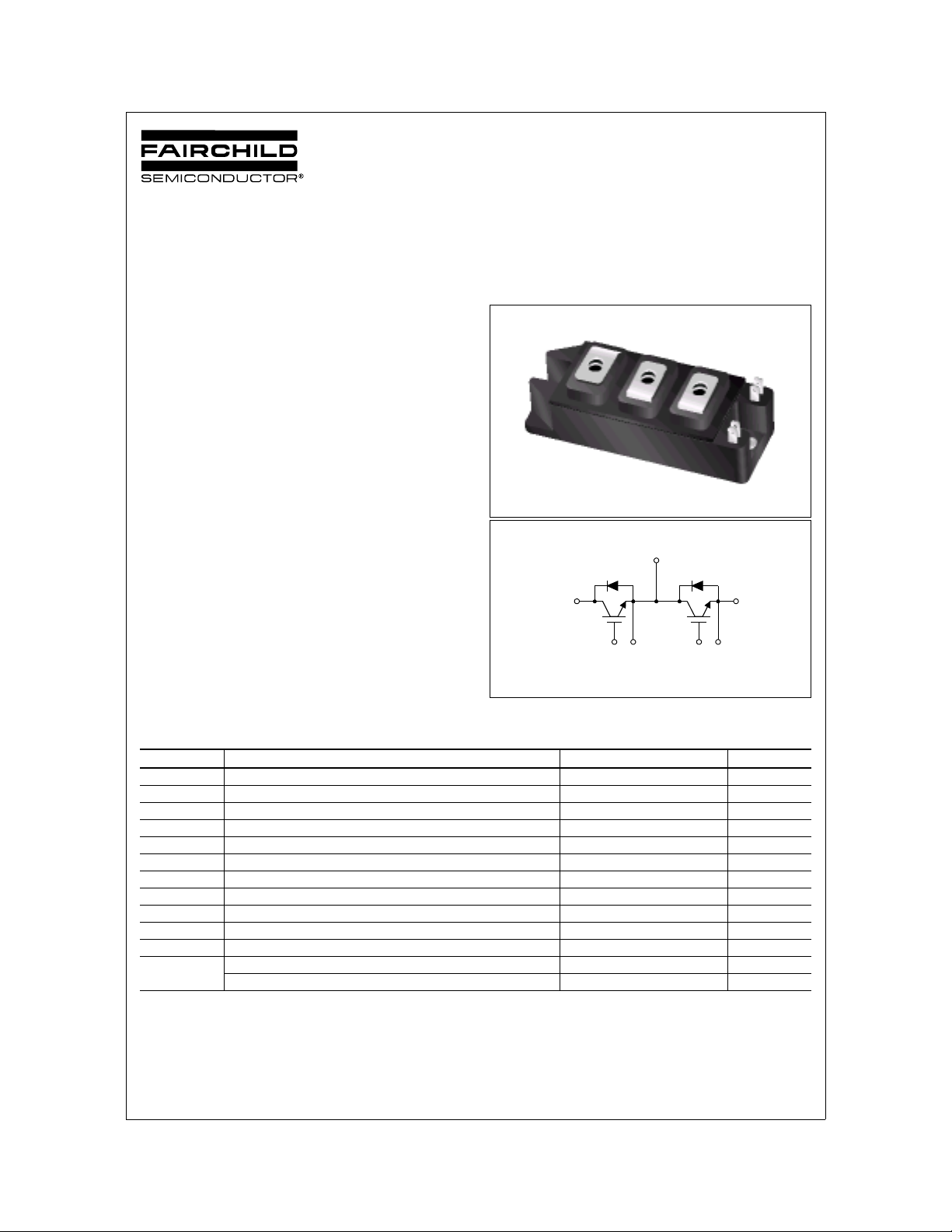
Molding Type Module
General Description
Fairchild’s Insulated Gate Bipolar Transistor (IGBT) power
modules provide low conduction and switching losses as
well as short circuit ruggedness. They are designed for
applications such as motor control, uninterrupted power
supplies (UPS) and general inverters wher e short circuit
ruggedness is a required feature.
Features
• UL Certified No. E209204
• Short Circuit rated 10us @ T
• High Speed Switching
• Low Saturation Voltage : V
• High Input Impedance
• Fast & Soft Anti-Parallel FWD
Application
• AC & DC Motor Controls
• General Purpose Inverters
• Robotics
• Servo Controls
•UPS
= 100°C, VGE = 15V
C
= 2.2 V @ IC = 75A
CE(sat)
Package Code : 7PM-GA
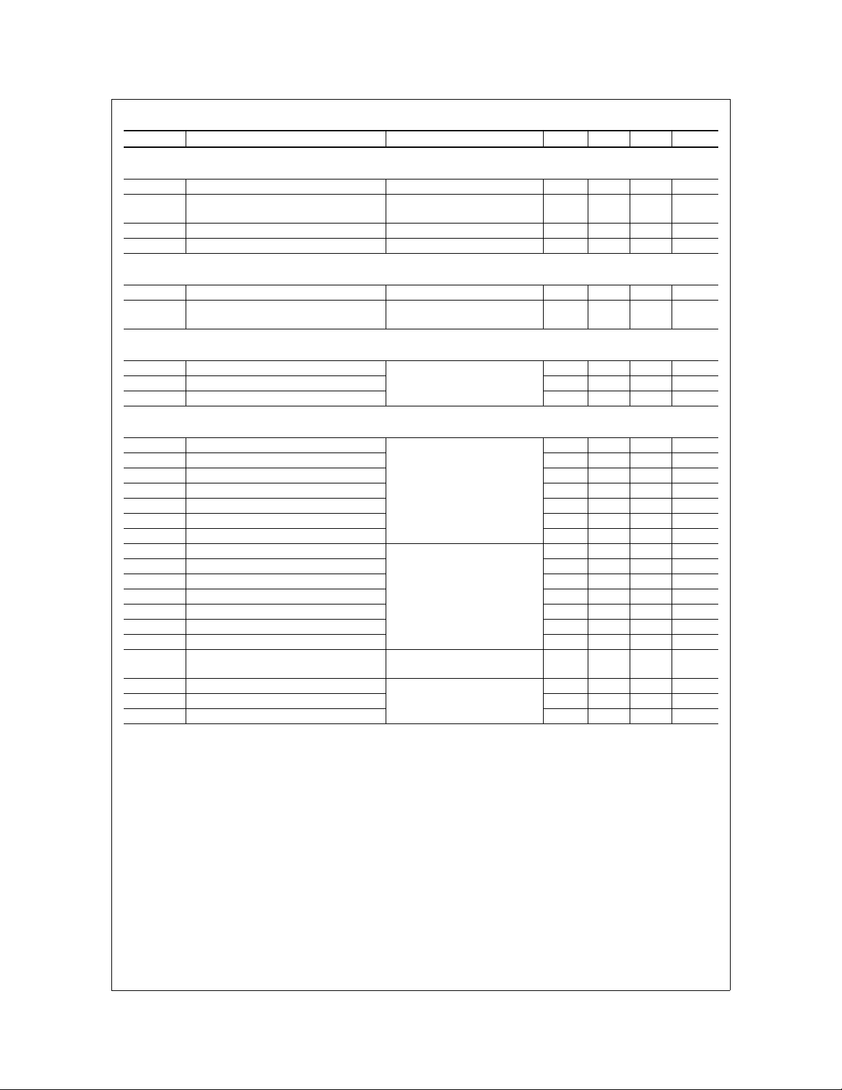
E1/C2
C1 E2
G1 E1 G2 E2
Internal Circuit Diagram
IGBT
Absolute Maximum Ratings T
Symbol Description FMG2G75US60 Units
V
CES
V
GES
I
C
I
CM (1)
I
F
I
FM
T
SC
P
D
Operating Junction Temperature -40 to +150 °C
T
J
T
stg
V
iso
Mounting
Torque
Notes :
(1) Repetitive rating : Pulse width limited by max. junction temperature
©2001 Fairchild Semiconductor Corporation FMG2G75US60 Rev. A
Collector-Emitter Voltage 600 V
Gate-Emitter Voltage ± 20 V
Collector Curent @ TC = 25°C75 A
Pulsed Collector Current 150 A
Diode Continuous Forward Current @ TC = 100°C75 A
Diode Maximum Forward Current 150 A
Short Circuit Withstand Time @ TC = 100°C10 us
Maximum Power Dissipation @ TC = 25°C 310 W
Storage Temperature Range -40 to +125 °C
Isolation Voltage @ AC 1minute 2500 V
Power Terminals Screw : M5 2.0 N.m
Mounting Screw : M5 2.0 N.m
= 25°C unless otherwise noted
C
FMG2G75US60
Electrical Characteristics of IGBT T
= 25°C unless otherwise noted
C
Symbol Parameter Test Conditions Min. Typ. Max. Units
Off Characteristics
BV
∆B
∆T
I
CES
I
GES
CES
VCES
J
Collector-Emitter Breakdown Voltage VGE = 0V, IC = 250uA 600 -- -- V
/
Temperature Coeff. of Breakdown
Voltage
Collector Cut-Off Current VCE = V
G-E Leakage Current VGE = V
V
= 0V, IC = 1mA -- 0.6 -- V/°C
GE
, VGE = 0V -- -- 250 uA
CES
, VCE = 0V -- -- ± 100 nA
GES
On Characteristics
V
GE(th)
V
CE(sat)
G-E Threshold Voltage VGE = 0V, IC = 75mA 5.0 6.0 8.5 V
Collector to Emitter
Saturation Voltage
= 75A, VGE = 15V
I
C
-- 2.2 2.8 V
Dynamic Characteristics
C
ies
C
oes
C
res
Input Capacitance
Output Capacitance -- 672 -- pF
Reverse Transfer Capacitance -- 180 -- pF
= 30V, VGE = 0V,
V
CE
f = 1MHz
-- 7056 -- pF
Switching Characteristics
t
d(on)
t
r
t
d(off)
t
f
E
on
E
off
Total Switching Loss -- 3.1 -- mJ
E
ts
t
d(on)
t
r
t
d(off)
t
f
E
on
E
off
E
Total Switching Loss -- 4.6 -- mJ
ts
T
sc
Q
g
Q
ge
Q
gc
Turn-On Delay Time
Rise Time -- 40 -- ns
Turn-Off Delay Time -- 70 -- ns
Fall Time -- 110 200 ns
Turn-On Switching Loss -- 1.4 -- mJ
= 300 V, IC = 75A,
V
CC
= 3.3Ω, V
R
G
GE
Inductive Load, T
= 15V
= 25°C
C
Turn-Off Switching Loss -- 1.7 - - mJ
Turn-On Delay Time
Rise Time -- 50 -- ns
Turn-Off Delay Time -- 80 -- ns
Fall Time -- 250 -- ns
Turn-On Switching Loss -- 1.6 -- mJ
= 300 V, IC = 75A,
V
CC
= 3.3Ω, V
R
G
Inductive Load, T
GE
= 15V
= 125°C
C
Turn-Off Switching Loss -- 3.0 - - mJ
= 300 V, V
V
Short Circuit Withstand Time
Total Gate Charge
Gate-Emitter Charge -- 62 -- nC
Gate-Collector Charge -- 130 -- nC
CC
@
TC = 100°C
= 300 V, IC = 75A,
V
CE
= 15V
V
GE
GE
= 15V
-- 20 -- ns
-- 20 -- ns
10 -- -- us
-- 310 350 nC
©2001 Fairchild Semiconductor Corporation FMG2G75US60 Rev. A
FMG2G75US60
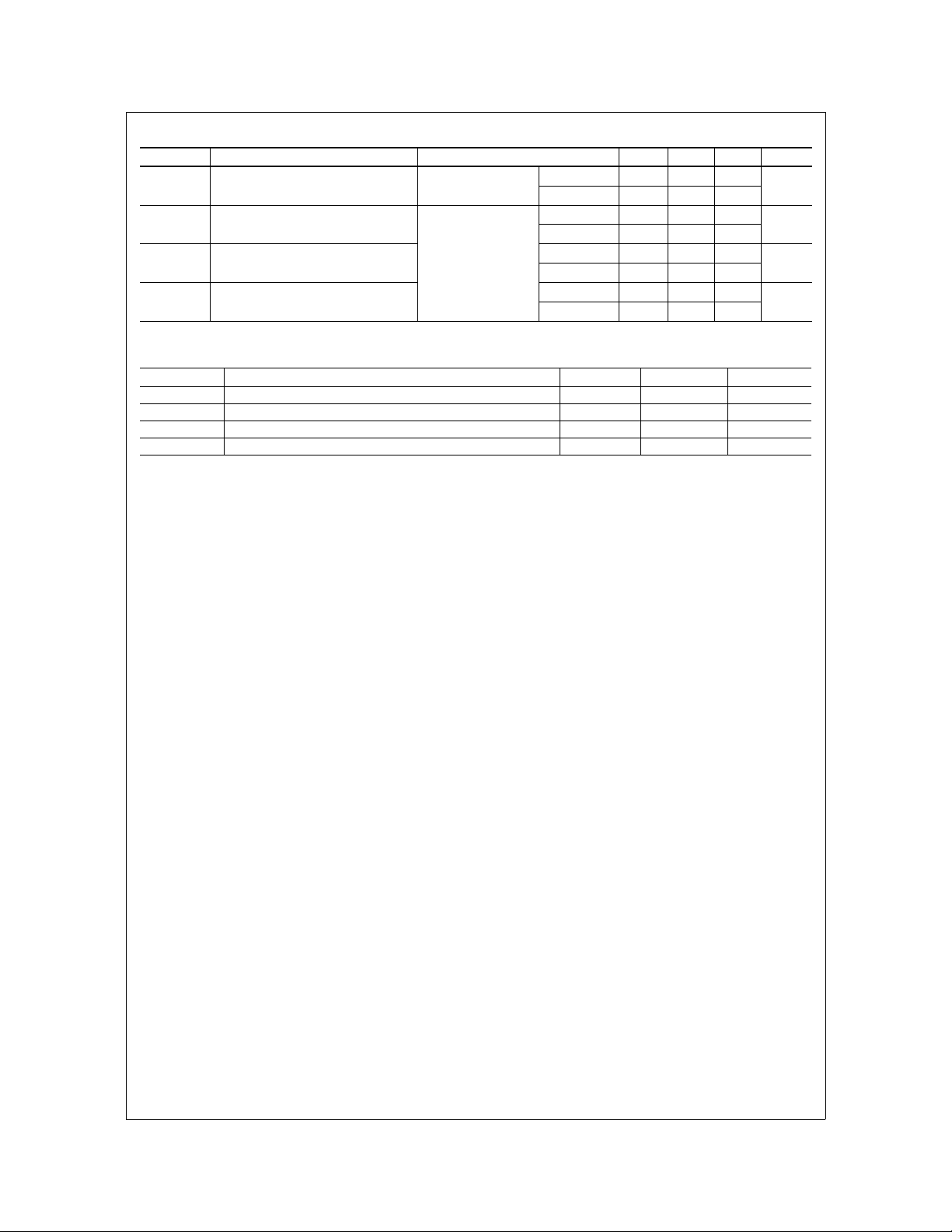
Electrical Characteristics of DIODE T
= 25°C unless otherwise noted
C
Symbol Parameter Test Conditions Min. Typ. Max. Units
T
= 25°C
V
FM
t
rr
I
rr
Q
rr
Diode Forward Voltage IF = 75A
Diode Reverse Recovery Time
I
Diode Peak Reverse Recovery
Current
= 75A
F
di / dt = 150 A/us
Diode Reverse Recovery Charge
C
T
C
T
C
T
C
T
C
T
C
T
C
T
C
= 100°C
= 25°C
= 100°C
= 25°C
= 100°C
= 25°C
= 100°C
-- 1.9 2.8
-- 1.8 --
-- 90 130
-- 130 --
-- 7 9
-- 10 --
-- 315 590
-- 650 --
Thermal Characteristics
Symbol Parameter Typ. Max. Units
R
θJC
R
θJC
R
θCS
Weight Weight of Module -- 190 g
Junction-to-Case (IGBT Part, per 1/2 Module) -- 0.4 °C/W
Junction-to-Case (DIODE Part, per 1/2 Module) -- 0.9 °C/W
Case-to-Sink (Conductive grease applied) 0. 05 -- °C/W
V
ns
A
nC
©2001 Fairchild Semiconductor Corporation FMG2G75US60 Rev. A
 Loading...