

Fairchild Semiconductor FES16BT, FES16AT, FES16JT, FES16HT, FES16GT Datasheet
...
Discrete POWER & Signal
FES16AT - FES16JT
FES16AT - FES16JT
Technologies
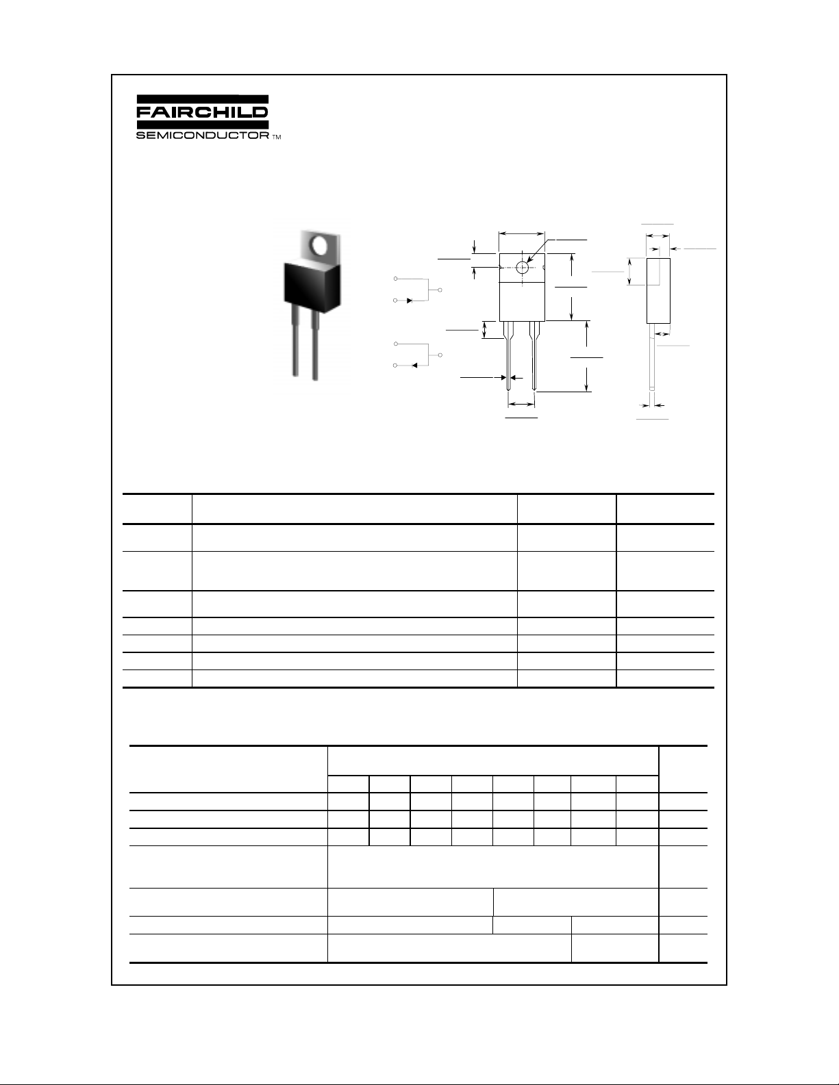
.185(4.70)
.175(4.44)
Features
• Low forward voltage drop.
• High surge current capacity.
• High current capability.
• High reliability.
PIN 1 +
PIN 2 -
CASE Positive
PIN 1 -
PIN 2 +
CASE N egative
Suffix “R”
.113( 2.87)
.103( 2.62)
+
CASE
+
.16(4.06)
.14(3.56)
.037( 0.94)
.027( 0.68)
.412( 10.5)
MAX
12
DIA
.154( 3.91)
.148( 3.74)
.594( 15.1)
.587( 14.91)
.56(14.22)
.53(13.46)
.27(6.86)
.23(5.84)
TO-220AC
.205( 5.20)
.195( 4.95)
Dimensions are in:
inches (mm)
.025(0.64)
.014(0.35)
16 Ampere Glass Passivated Super Fast Rectifiers
Absolute Maximum Ratings* T
Symbol Parameter Value Units
I
O
i
f(surge)
P
D
R
θ
JA
R
θ
JL
T
stg
T
J
*These ratings are limiting values above which the serviceability of any semiconductor device may be impaired.
Average Rectified Current
.375 " lead length @ T
Peak Forward Surge Current
8.3 ms single half-sine-wave
Superimposed on rated load (JEDEC method)
Total Device Dissipation
Derate above 25°C
Thermal Resistan ce, Junction to Ambient 16
Thermal Resistance, Junction to Lead 1.2
Storage Temperature Range -65 to +150
Operating Junction Temperature -65 to +150
= 25°C unless otherwise noted
A
= 100°C
A
16 A
250 A
7.81
62
mW/°C
C/W
°
C/W
°
.11(2.79)
.10(2.54)
W
C
°
C
°
.055(1.40)
.045(1.14)
Electrical Characteristics T
= 25°C unless otherwise noted
A
Parameter Device Units
16AT 16BT 16CT 16DT 16FT 16GT 16HT 16JT
Peak Repetitive Reverse Voltage 50 100 150 200 300 400 500 600 V
Maximum RMS Voltage 35 70 105 140 210 280 350 420 V
DC Blocking Voltage (Rated VR)
Maximum Reverse Current
@ rated V
R
Maximum Rev erse Recovery Time
= 0.5 A, IR = 1.0 A, I
I
F
Maximum Forward Voltage @ 16.0A
Typical Junction Capacitance
V
= 4.0. f = 1.0 MHz
R
1999 Fairchild Semiconductor Corporation
TA = 25°C
= 100°C
T
A
= 0.25 A
RR
50 100 150 200 300 400 500 600 V
10
500
35 50
0.975 1.3 1.5 V
170 145 pF
FES16AT - FES16JT, Rev. A
µ
µ
nS
A
A
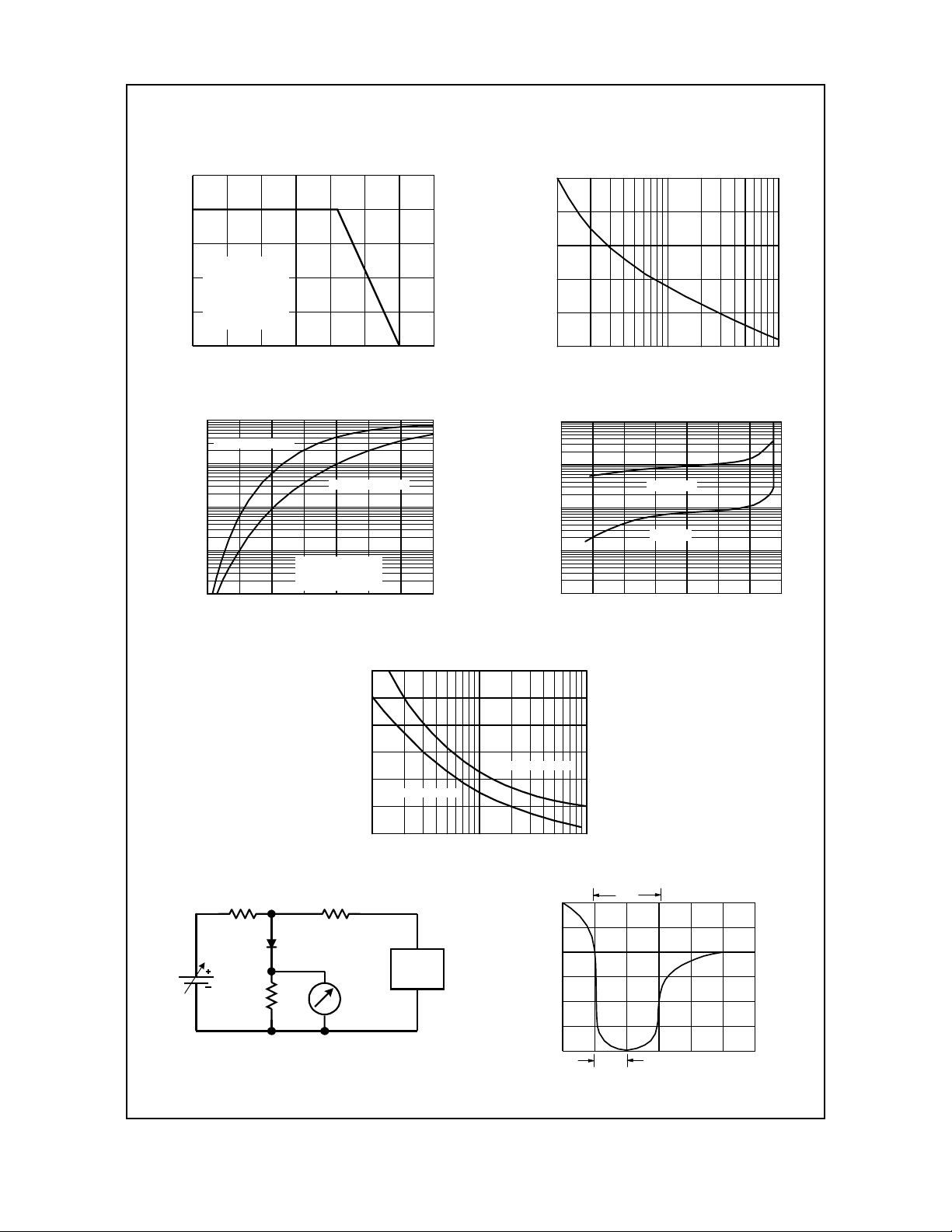
T ypical Characteristics
FES16AT - FES16JT
Forward Current Derating Curve
20
16
12
SINGLE PHASE
HALF WAVE
8
60HZ
RESISTIVE OR
INDUCTIVE LOAD
4
.375" (9.0mm) LEAD
FORWARD CU RRENT (A)
LENGTHS
0
0 255075100125150175
AMBI ENT TEMPERATURE ( C)
º
Forward Charact eristics
100
FES16AT-FES16DT
10
FES16FT-FES16JT
1
0.1
FORWARD CURRENT (A)
0.01
0.4 0.6 0.8 1 1.2 1.4 1.6 1.8
FORWARD VOLTAGE (V)
º
T = 25 C
A
Pulse Width = 300µs
2% Duty Cycle
Non-Repetitive Surge Current
250
200
150
100
50
0
PEA K FORWARD SURG E CUR R EN T (A)
1 2 5 10 20 50 100
NUMBER OF CYCLES AT 60Hz
Reverse Characteristics
1000
µ
100
T = 100 C
º
A
10
º
T = 25 C
1
REVERSE CURRENT ( A)
0.1
0 20406080100120140
PER CENT OF R ATED PE AK REVERSE VO LT AGE (%)
A
300
250
200
50
Ω
NONINDUCTIVE
50V
(approx)
Ω
50
NONINDUCTIVE
Ω
50
NONINDUCTIVE
DUT
150
100
FES16FT-FES16JT
CAPACITANCE (pF)
50
0
1 2 5 10 20 50 100
REVERSE VOLTAGE (V)
(-)
Pulse
Generator
(Note 2)
OSCILLOSCOPE
(Note 1)
(+)
FES16AT- F E S 16D T
+0.5A
0
-0.25A
-1.0A
1.0cm SET TIME BASE FOR
trr
Reverse Recovery Time Characterstic and Test Circuit Diagram
Junction Capacitance
5/ 10 ns/ cm
FES16AT - FES16JT, Rev. A
 Loading...