

Fairchild BAT54, BAT54A, BAT54C, BAT54S service manual

BAT54/A/C/S
Schottky Diodes
3
2
1
SOT-23
3
L4P
12
MARKING
= L4P
BAT54
= L43
BAT54C
BAT54A = L42
BAT54S = L44
April 2012
Connection Diagram
BAT54 BAT54A
3
1
2NC
3
2
1
3
2
1
BAT54SBAT54C
3
2
1
BAT54/A/C/S — Schottky Diodes
Absolute Maximum Ratings * T
= 25°C unless otherwise noted
a
Symbol Parameter Value Unit
V
RRM
I
F(AV)
I
FSM
T
STG
T
* These ratings are limiting values above which the serviceability of any semiconductor device may be impaired.
Maximum Repetitive Reverse Voltage 30 V
Average Rectified Forward Current 200 mA
Non-repetitive Peak Forward Surge Current
600 mA
Pulse Width = 1.0 second
Storage Temperature Range -55 to +150 °C
Operating Junction Temperature -55 to +150 °C
J
Thermal Characteristics
Symbol Parameter Value Unit
P
R
θJA
Electrical Characteristics
Symbol Parameter Conditions Min. Max. Units
V
V
I
R
C
t
rr
Power Dissipation 290 mW
D
Thermal Resistance, Junction to Ambient 430 °C/W
TC = 25°C unless otherwise noted
Breakdown Voltage IR = 10μA30V
R
Forward Voltage IF = 0.1mA
F
I
= 1mA
F
= 10mA
I
F
= 30mA
I
F
IF = 100mA
240
320
400
500
0.8
Reverse Leakage VR = 25V 2 μA
Total Capacitance VR = 1V, f = 1.0MHz 10 pF
T
Reverse Recovery Time IF = IR = 10mA, IRR = 1.0mA,
= 100Ω
R
L
5.0 ns
mV
mV
mV
mV
V
© 2012 Fairchild Semiconductor Corporation www.fairchildsemi.com
BAT54/A/ C/S Rev. E2 1
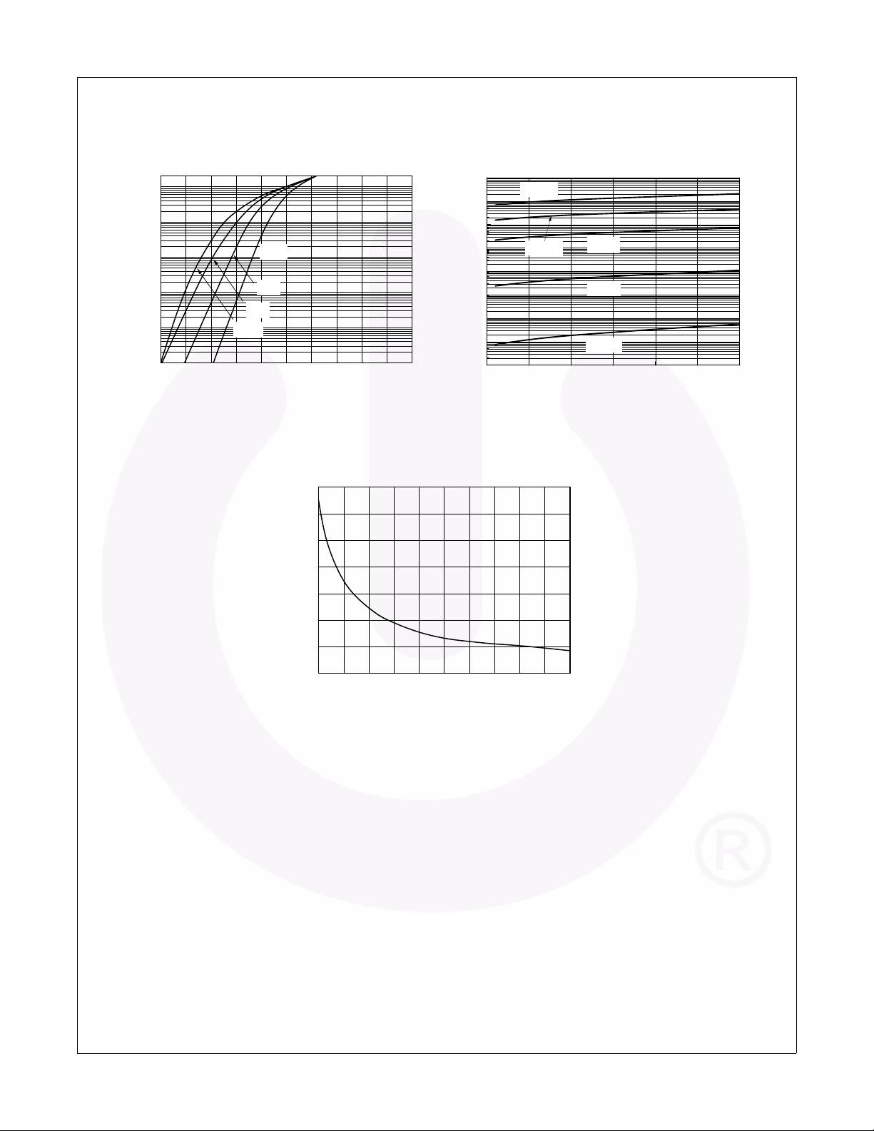
Typical Performance Characteristics
BAT54/A/C/S — Schottky Diodes
-1
10
-2
10
-3
10
-4
10
-Forward Current [A]
F
I
-5
10
-6
10
0.0 0.1 0.2 0.3 0.4 0.5 0.6 0.7 0.8 0.9 1.0
-25oC
25oC
75oC
100oC
VF-Forward Voltage [V]
Figure 1. Forward Current vs. Forward Voltage
16
14
12
10
8
1000
100
10
[μA]
R
0.1
0.01
1E-3
Reverse Current, I
1E-4
1E-5
TA=125oC
1
TA=100oC
0 5 10 15 20 25 30
TA=75oC
TA=25oC
TA=-25oC
Reverse Voltage, VR [V]
Figure 2. Reverse Current vs. Reverse Voltage
6
Capacitance [pF]
4
2
012345678910
VR-Reverse Voltage [V]
Figure 3. Total Capacitance vs. Reverse Voltage
© 2012 Fairchild Semiconductor Corporation www.fairchildsemi.com
BAT54/A/ C/S Rev. E2 2
 Loading...