

Fagor ACSD series Original Instructions Manual
FAGOR AUTOMATION S.COOP.
Brushless AC
Servo Drives
~ ACSD series ~
Ref.1609
Original instructions

Title Brushless AC Servo Drives. ACSD series.
Type of documentation Description, installation and startup of motors and dig-
ital drives.
Name MAN REGUL ACSD (IN)
Reference Ref.1609
Software Version 02.04 and earlier versions
WinDDSSetup Version 08.15
Electronic document man_acsd. pdf
Headquarters FAGOR AUTOMATION S.COOP.
B.º San Andrés 19, Apdo. 144
E- 20500 ARRASATE- MONDRAGÓN
www.fagorautomation.com
info@fagorautomation.es
34-943-719200
34-943-771118 (Technical Support )
The information described in this manual may be subject to changes
due to technical modifications. FAGOR AUTOMATION, S. Coop.
reserves the right to change the contents of this manual without prior
notice.
The contents of this manual have been verified and matched with the
product described here. Even so, it may contain involuntary errors that
make it impossible to ensure an absolute match. However, the
contents of this document are regularly checked and updated
implementing the necessary corrections in a later edition.
All rights reserved. No part of this documentation may be copied,
transmitted, transcribed, stored in a backup device or translated into
another language without Fagor Automation’s permission.
DUAL-USE products.
Products manufactured by Fagor Automation S. Coop. included
on the list of dual-use products according to regulation (UE) Nr
1382/2014. Their product identification includes the text -MDU
and require an export license depending on destination.
ACSD-2/80 Digital Brushless AC Servo Drive system - Ref.1609

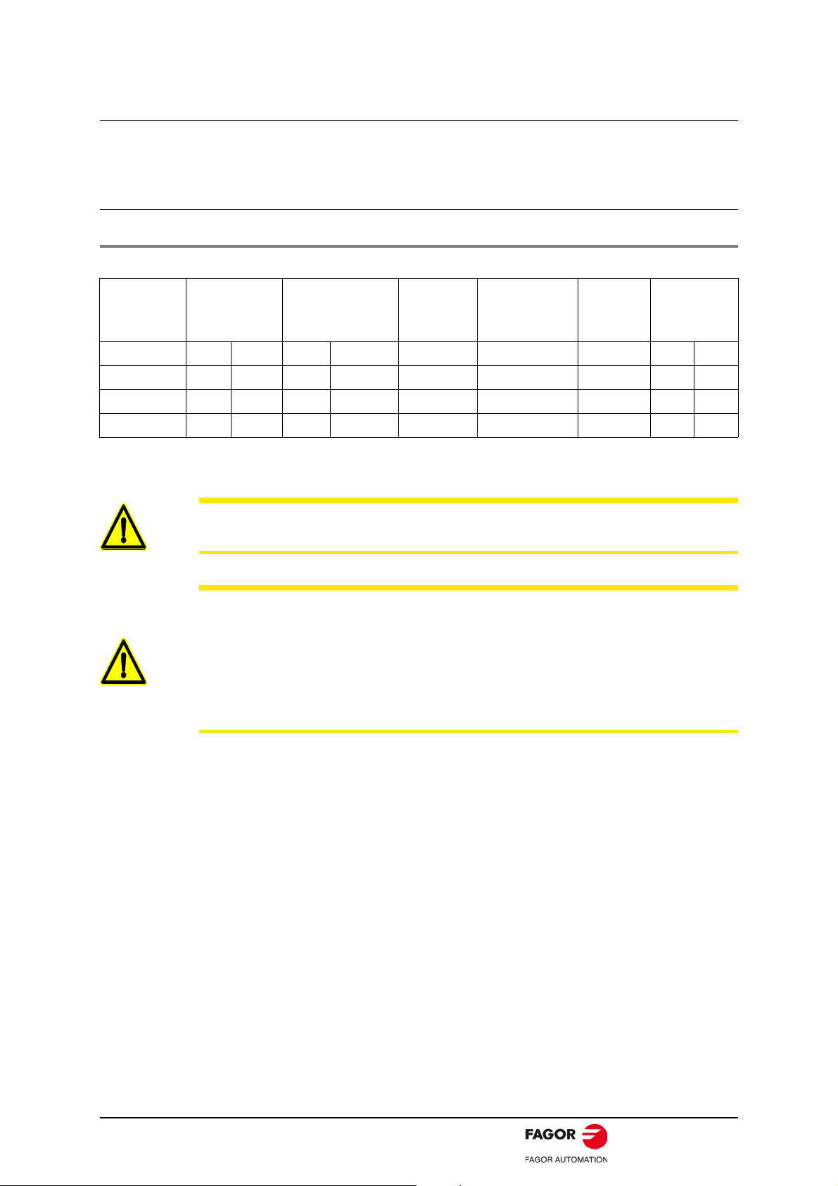
WARRANTY CONDITIONS
FAGOR AUTOMATION guarantees its products for the period of time with the exceptions indicated below, against
defects in design, materials used and manufacturing process that affect the correct operation of the product.
The warranty period will have an initial duration of 24 months, applicable to all FAGOR products from the date
the material is shipped to the customer. The manufacturers (OEM) or distributors will have a maximum period
of 12 months from the time the product leaves FAGOR AUTOMATION warehouse to register the warranty. If the
manufacturer, distributor and/or end user registers or informs FAGOR AUTOMATION regarding the final
destination, date of installation and identification of the machine through any of the methods described by
FAGOR AUTOMATION Product Warranty registration process, this warranty will be commence for 24 months
period from the date of registration, with a maximum limit of 36 months from the time the product leaves the
facilities of FAGOR AUTOMATION; i.e., the period between the product shipping date and the date the warranty
ends must not exceed a total of 36 months.
If a product has never been registered, the warranty period will end 24 months from the time the product leaves
FAGOR AUTOMATION's warehouses. After this period, a warranty extension contract, for the material, must
be executed or a specific agreement reached with FAGOR AUTOMATION.
In the case of new replacement parts, the applicable warranty will be 12 months. With repaired products or in
those cases where the product exchange option was used, during outside product warranty period-the
applicable warranty will be provided by the corresponding repair center. When a repair estimate is provided it
pertains to a specific defective item/s hence the warranty only covers the replaced part.
FAGOR guarantees to provide service for all current products and until 8 years after the date they are removed
from the current catalog including repair, providing replacement part service or replacing the product with
another identical or equivalent model. A backward compatible solution is available for most products i.e. the
product can be upgraded to a newer model.
It is entirely up to FAGOR to determine whether the repair is to be considered under warranty.
During the warranty period, and following identification and diagnosis, FAGOR AUTOMATION will only repair
or replace the product/part assessed to be defective. FAGOR AUTOMATION is not liable for any other
compensation.
FAGOR AUTOMATION at its sole discretion reserves the right either to repair or replace the affected product
during warranty period.
This product warranty covers all costs of materials and labor to repair or correct the cause of defect. The repairs
will be carried out at the facilities of FAGOR AUTOMATION, unless it is agreed between FAGOR AUTOMATION
and the CUSTOMER to carry out the repairs on the premises of the CUSTOMER or end user. Unless there is
a specific agreement in cases of onsite repair all expenses related to diagnosis, labor, travel expenses,
shipping costs, etc. are excluded and will be billed according to FAGOR AUTOMATION's established rate. The
customer/user will be notified in advance of the estimate of charges when applicable.
The part/s replaced under warranty will be a property of FAGOR AUTOMATION.
FAGOR AUTOMATION offers to its customers an extension to the standard warranty and comprehensive
warranty services through SERVICE CONTRACTS that meet the diverse needs of customers.
Excluded from this warranty are:
a) Deteriorated/Defective components as the result of mishandling, in violation of safety rules or the technical
specifications of the product, inadequate monitoring or any type of negligence on behalf of the CUSTOMER.
b) Defects caused by improper handling, assembly and/or installation by the CUSTOMER or caused by
modifications or repairs carried out without the consent of FAGOR AUTOMATION.
c) Defects caused due to specific materials, fluids/coolants, electricity power or services used by the CUSTOMER.
d) The malfunctions caused by unforeseen circumstances or force majeure (weather or geological events) and
accidents or any other type of natural disaster.
e) In a general sense, any indirect, consequential and/or collateral damage.
f) Damage caused during transport.
All service requests during the warranty period must be communicated to FAGOR AUTOMATION, identifying
the product (serial number), describing in detail the symptoms observed, the reason for the malfunction (if
known) and its scope.
All components replaced within the warranty period are covered by the warranty until the expiration of the
original warranty period of the product.
The warranty offered by FAGOR AUTOMATION will become null and void in the event that the CUSTOMER
fails to comply with the installation and operation requirements and recommendations regarding preventive and
corrective maintenance as indicated in product manuals.
Digital Brushless AC Servo Drive system - Ref.1609 ACSD-3/80
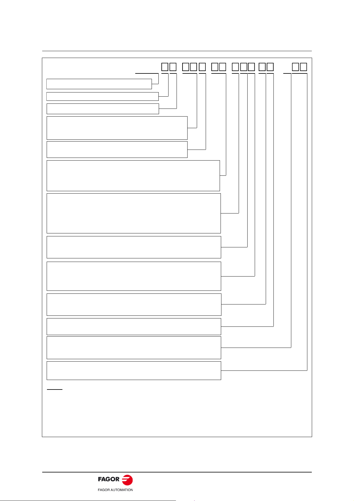
DECLARATION OF CONFORMITY
Manufacturer: Fagor Automation, S. Coop.
B.º San Andrés 19, C.P. 20500, Mondragón - Gipuzkoa - (SPAIN)
We hereby declare, under our responsibility that the product:
FAGOR AC BRUSHLESS SERVODRIVE SYSTEM
Parameter setting for the drive modules.
ACSD-05L, ACSD-10L, ACSD-20L, ACSD-30L
ACSD-04H, ACSD-08H, ACSD-16H
and feed axis servo motors:
FXM1, FXM3, FXM5, FXM7, FKM2, FKM4, FKM6
Note. Some additional characters may follow the model references indicated above.
They all comply with the directives listed here. However, compliance may be verified
on the label of the unit itself.
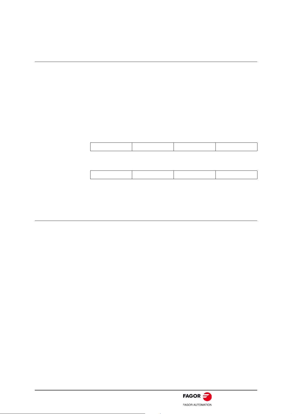
mentioned on this declaration, meet the requirements on:
Safety
EN 60204-1:2007
CORR:2010
Electromagnetic Compatibility
EN 61800-3:2004
/A1:2012
In compliance with EC Directives 2014/35/UE on Low Voltage and 2014/30/UE on
Electrical Compatibility.
Machinery safety. Electrical equipment of the machines.
Part 1: General requirements.
EMC directive on servo drive systems.
In Mondragón September 1st 2016
INTRODUCTION
FAGOR offers you a wide range of servo drive systems (AC Brushless motor + Digital
Drive) for applications requiring between 1.2 and 33.6 N·m at speeds between 1200
rev/min and 4000 rev/min for FXM motors and between 1.7 and 23.5 N·m at speeds
between 2000 rev/min and 6000 rev/min for FKM motors.
This manual describes the elements in detail and guides step by step through the
installation and setup of the drive system.
When installed for the first time, read the whole document.
Should you have any doubts or questions, please do not hesitate to contact our
technicians at any of our subsidiaries worldwide.
Thank you for choosing FAGOR.
ACSD-4/80 Digital Brushless AC Servo Drive system - Ref.1609

General index
BRUSHLESS AC MOTORS, FXM ..............................................................................7
Introduction ..................................................................................................................7
General characteristics ................................................................................................7
Dimensions ................................................................................................................11
Power connector ........................................................................................................13
Motor feedback connector..........................................................................................14
Holding brake .............................................................................................................15
Sales reference ..........................................................................................................16
BRUSHLESS AC MOTORS, FKM ............................................................................17
Introduction ................................................................................................................17
General characteristics ..............................................................................................17
Dimensions ................................................................................................................20
Power connector ........................................................................................................21
Motor feedback connector..........................................................................................22
Holding brake .............................................................................................................23
Sales reference ..........................................................................................................24
COMPACT SERVO DRIVE, ACSD ...........................................................................25
Introduction ................................................................................................................25
General characteristics ..............................................................................................25
Dimensions ................................................................................................................26
Technical data............................................................................................................26
Connectors.................................................................................................................27
Indicators....................................................................................................................28
Push-buttons and switches ........................................................................................29
Front panel and pinout of the connectors...................................................................30
Unit identification........................................................................................................32
Sales reference ..........................................................................................................32
INSTALLATION.........................................................................................................33
General considerations ..............................................................................................33
Electrical connections ................................................................................................34
Cables ........................................................................................................................40
CAN field bus connection...........................................................................................41
Codes of the FAGOR cables......................................................................................42
Connecting a drive to a PC. RS-232 serial line..........................................................43
Diagram of the electrical cabinet................................................................................44
Initialization and adjustment.......................................................................................45
PARAMETERS, VARIABLES & COMMANDS .........................................................49
Notation......................................................................................................................49
Groups .......................................................................................................................51
ERROR CODES ........................................................................................................71
PARAMETERS, VARIABLES & COMMANDS. IDs..................................................76
Digital Brushless AC Servo Drive system - Ref.1609 ACSD-5/80

This page intentionally left blank
ACSD-6/80 Digital Brushless AC Servo Drive system - Ref.1609

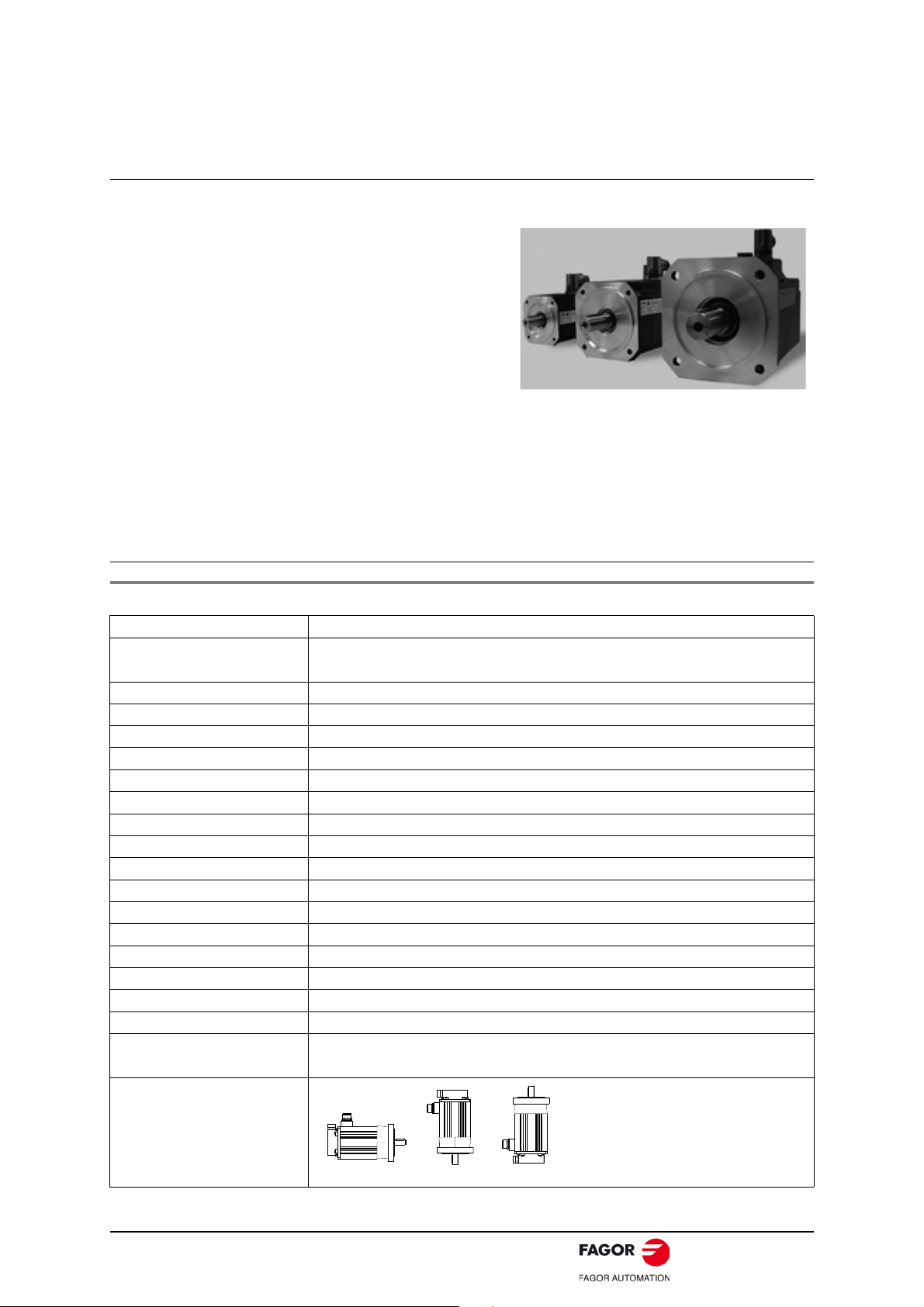
BRUSHLESS AC MOTORS, FXM
FXM series synchronous servo motors are AC
Brushless, with permanent magnets.
They are ideal for any application requiring
great positioning accuracy. They have a uniform output torque, high reliability and low maintenance. They are designed to meet the IP 64
protection standard and, therefore, they are
immune to liquid and dirt.
F X M 1 F X M 3 F X M 5 F X M 7
IP 64 means that it is protected against dust and against water jets. They incorporate
a temperature sensor for monitoring the internal temperature. They also carry an
optional electromechanical brake. The F class isolation on the motor maintains the
dielectric properties as long as the work temperature stays below 150°C/302°F.
IM B5
IM V3
IM V1
Introduction
General characteristics
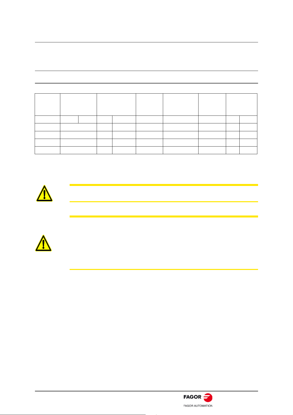
T. 6 FXM servomotors. General characteristics.
Excitation Permanent rare earth magnets (SmCo)
Temperature sensor PTC thermistor. Triple
Shaft end Cylindrical with keyway (optional with no keyway)
Mounting Face flange
Mounting method IM B5 - IM V1 - IM V3 (as recommended by IEC-34-3-72)
Mechanical tolerances Normal class (meets IEC-72/1971)
Balancing Class N (R optional) (DIN 45665) whole-key balancing
Roller bearings’ life 20000 hours
Noise DIN 45635
Vibration resistance Withstands 1g, along the shaft and 3g sideways (g=9.81 m/s²)
Electrical insulation Class F (150°C/302°F)
Insulation resistance 500 V DC, 10 M or greater
Dielectric rigidity 1500 V AC, one minute
Protection degree General: Standard IP 64. Shaft: Standard IP 64, IP 65 with oil seal
Storage temperature -20°C/+80°C (-4°F/+176°F)
Ambient temperature 0°C/+40°C (+32°F/+104°F)
Working ambient humidity From 20% to 80% (non condensing)
Holding brake Optional. See technical data ·holding brake·
Feedback
I0 Incremental TTL encoder ·2500 ppt·
E1/A1 Sincoder encoder / SinCos multi-turn abs. encoder ·1024 ppv·
Meaning of the
codes of
the mounting
method.
Digital Brushless AC Servo Drive system - Ref.1609 ACSD-7/80
Drive
2
peak torque
Mass
1
Inertia
per phase
Resistance
per phase
Inductance
time
Acceleration
constant
Torque
power
Calculation
current
Peak
current
Stall
speed
Rated
torque
Stall peak
Stall torque
Mo Mp nN Io Imax Pcal kt tac L R J M ACSD-05L ACSD-10L ACSD-20L ACSD-30L
N·m N·m rpm A A kW N·m/A ms mH kg·cm² kg N·m N·m N·m N·m
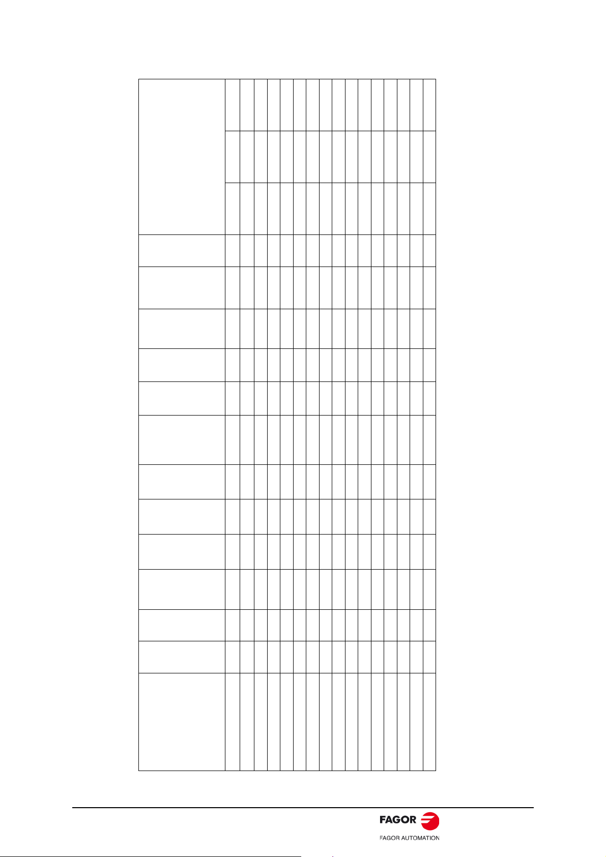
. 17.3 86 2000 15.0 74.6 3.6 1.1 8.8 2.5 0.19 36.0 20.0 33.6
motors
Non-ventilated
T. 2 Technical data of non-ventilated synchronous FXM motors with “F” winding (220 V AC).
FXM53.20F.. 11.9 59 2000 9.9 49.1 2.5 1.2 7.8 5.0 0.45 22.0 15.8 24.0 36.0
FXM53.30F.. 11.9 59 3000 14.8 73.0 3.7 0.8 11.7 2.2 0.20 22.0 15.8 24.0
FXM54.20F.. 14.8 74 2000 12.7 63.5 3.1 1.2 8.2 3.4 0.27 29.0 17.8 36.0
FXM55.12F.. 17.3 86 1200 9.1 45.2 2.2 1.9 5.3 7.2 0.55 36.0 20.0 38.0 57.0
FXM73.12F.. 20.8 104 1200 10.7 53.5 2.6 1.9 7.4 9.8 0.60 61.0 29.0 57.0
FXM55.20F.
FXM11.40F.. 1.2 6 4000 2.0 10.0 0.5 0.6 8.4 12.0 4.60 1.2 3.3 3.0 6.0
FXM12.40F.. 2.3 11 4000 3.9 18.7 1.0 0.6 7.2 5.5 1.45 1.9 4.3 6.0 11.0
FXM13.40F.. 3.3 16 4000 5.6 27.2 1.4 0.6 6.8 3.5 0.80 2.6 6.4 12.0 16.0
FXM14.20F.. 4.1 20 2000 3.5 17.1 0.9 1.2 3.5 10.0 2.30 3.3 7.6 12.0 20.0
FXM14.40F.. 4.1 20 4000 6.9 33.7 1.7 0.6 6.9 2.6 0.55 3.3 7.6 12.0 18.0
FXM31.20F.. 2.6 13 2000 2.2 11.0 0.5 1.2 5.6 24.0 5.05 3.5 5.5 6.0 12.0 13.0
FXM31.40F.. 2.6 13 4000 4.4 22.0 1.1 0.6 11.3 6.1 1.25 3.5 5.5 6.0 12.0 13.0
FXM32.20F.. 5.1 25 2000 4.3 21.1 1.1 1.2 5.0 11.0 1.65 6.0 7.5 12.0 24.0 25.0
FXM32.40F.. 5.1 25 4000 8.4 41.2 2.1 0.6 10.0 2.9 0.44 6.0 7.5 12.0 18.0
FXM33.20F.. 7.3 36 2000 6.3 31.1 1.5 1.2 4.9 6.7 0.90 8.5 9.6 24.0 36.0
FXM33.40F.. 7.3 36 4000 12.0 59.2 3.1 0.6 9.9 1.8 0.25 8.5 9.6 18.0
FXM34.20F.. 9.3 46 2000 7.6 37.6 1.9 1.2 5.0 5.3 0.65 11.0 11.5 24.0 36.0
FXM34.40F.. 9.3 46 4000 15.0 74.2 3.9 0.6 10.0 1.3 0.17 11.0 11.5 18.0
ACSD-8/80 Digital Brushless AC Servo Drive system - Ref.1609
FXM74.12F.. 27.3 135 1200 13.5 66.8 3.4 2.0 7.3 7.8 0.45 79.0 31.6 60.0
FXM75.12F.. 29.5 165 1200 15.0 83.9 3.7 2.0 7.4 5.9 0.31 97.0 36.0 60.0
1. When adding the mechanical brake to the motor (option) also take into account the inertia values given in the table of section ·holding brake characteristics·.
. In the combinations shown in bold letters, the drive will limit its peak current automatically so as not to damage the motor.
2. When adding the mechanical brake to the motor (option) also take into account its mass values given in the table of section ·holding brake characteristics·.
NOTE
Drive
2
peak torque
Mass
1
Inertia
per phase
Resistance
per phase
Inductance
time
Acceleration
constant
Torque
power
Calculation
current
Peak
current
Stall
speed
Rated
torque
Stall peak
Stall torque
Mo Mp nN Io Imax Pcal kt tac L R J M ACSD-04H ACSD-08H ACSD-16H
N·m N·m rpm A A kW N·m/A ms mH kg·cm² kg N·m N·m N·m
. 5.1 25 3000 2.80 14.0 1.6 1.8 7.5 25 4.05 6.0 7.5 14.6 25.0
motors
Non-ventilated
T. 3 Technical data of non-ventilated synchronous FXM motors with “A” winding (400 V AC).
FXM11.40A.. 1.2 6 4000 0.90 4.5 0.5 1.3 8.4 62 23.5 1.2 3.3 5.2 6.0
FXM12.20A.. 2.3 11 2000 0.86 4.1 0.5 2.7 3.6 111 32.0 1.9 4.3 10.7 11.0
FXM12.30A.. 2.3 11 3000 1.29 6.2 0.7 1.8 5.4 49 13.0 1.9 4.3 7.1 11.0
FXM12.40A.. 2.3 11 4000 1.72 8.2 1.0 1.3 7.2 28 7.8 1.9 4.3 5.4 10.7 11.0
FXM13.20A.. 3.3 16 2000 1.23 6.0 0.7 2.7 3.4 71 16.0 2.6 6.4 10.7 16.0
FXM13.30A.. 3.3 16 3000 1.85 9.0 1.0 1.8 5.1 32 7.25 2.6 6.4 7.1 14.2 16.0
FXM13.40A.. 3.3 16 4000 2.50 12.0 1.4 1.3 6.8 18 4.05 2.6 6.4 10.6 16.0
FXM14.20A.. 4.1 20 2000 1.53 7.5 0.9 2.7 3.5 52 12.0 3.3 7.6 10.7 20.0
FXM14.30A.. 4.1 20 3000 2.30 11.2 1.3 1.8 5.2 23 4.85 3.3 7.6 14.2 20.0
FXM14.40A.. 4.1 20 4000 3.10 15.0 1.7 1.3 6.9 13 2.95 3.3 7.6 10.6 20.0
FXM31.20A.. 2.6 13 2000 0.97 4.8 0.5 2.7 5.6 126 29.0 3.5 5.5 10.7 13.0
FXM31.30A.. 2.6 13 3000 1.45 7.3 0.8 1.8 8.5 56 12.5 3.5 5.5 7.2 13.0
FXM31.40A.. 2.6 13 4000 1.92 9.6 1.1 1.4 11.3 32 7.25 3.5 5.5 5.4 10.8 13.0
FXM32.20A.. 5.1 25 2000 1.89 9.2 1.1 2.7 5.0 56 9.55 6.0 7.5 10.8 21.6 25.0
FXM32.40A.. 5.1 25 4000 3.80 18.5 2.1 1.4 10.1 14 2.3 6.0 7.5 10.7 21.4
FXM32.30A.
1. When adding the mechanical brake to the motor (option) also take into account the inertia values given in the table of section ·holding brake characteristics·.
2. When adding the mechanical brake to the motor (option) also take into account its mass values given in the table of section ·holding brake characteristics·.
FXM11.20A.. 1.2 6 2000 0.45 2.2 0.3 2.7 4.2 248 93.5 1.2 3.3 6.0
FXM11.30A.. 1.2 6 3000 0.67 3.4 0.4 1.8 6.3 110 43.0 1.2 3.3 6.0
Digital Brushless AC Servo Drive system - Ref.1609 ACSD-9/80
NOTE. In the combinations shown in bold letters, the drive will limit its peak current automatically so as not to damage the motor.
2
1
Drive
peak torque
Mass
Inertia
per phase
Resistance
per phase
Inductance
time
Acceleration
constant
Torque
power
current
Peak
current
Stall
speed
Rated
torque
Stall peak
torque
Stall
motors
Calculation
Mo Mp nN Io Imax Pcal kt tac L R J M ACSD-04H ACSD-08H ACSD-16H
N·m N·m rpm A A kW N·m/A ms mH kg·cm² kg N·m N·m N·m
Non-ventilated
FXM33.20A.. 7.3 36 2000 2.7 13.4 1.5 2.7 4.9 36 5.05 8.5 9.6 21.6 36.0
FXM33.30A.. 7.3 36 3000 4.1 20.0 2.3 1.8 7.4 16 2.20 8.5 9.6 14.2 28.5
FXM33.40A.. 7.3 36 4000 5.5 27.0 3.1 1.3 9.9 8.6 1.15 8.5 9.6 21.3
FXM34.20A.. 9.3 46 2000 3.4 17.0 1.9 2.7 5.0 26 3.45 11.0 11.5 21.9 43.8
FXM34.30A.. 9.3 46 3000 5.1 25.0 2.9 1.8 7.5 12 1.60 11.0 11.5 29.1
T. 4 Technical data of non-ventilated synchronous FXM motors with “A” winding (400 V AC).
FXM34.40A.. 9.3 46 4000 6.9 34.0 3.9 1.4 10.0 6.6 0.85 11.0 11.5 21.6
FXM53.12A.. 11.9 59 1200 2.8 14.0 1.5 4.2 4.7 61 5.85 22.0 15.8 34.0 59.0
FXM53.20A.. 11.9 59 2000 4.7 23.0 2.5 2.5 7.8 22 2.15 22.0 15.8 40.5
FXM53.30A.. 11.9 59 3000 7.1 35.0 3.7 1.7 11.7 9.6 0.91 22.0 15.8 26.9
FXM54.12A.. 14.8 74 1200 3.5 17.6 1.9 4.2 4.9 44 3.70 29.0 17.8 33.8 67.7
FXM54.20A.. 14.8 74 2000 5.9 30.0 3.1 2.5 8.2 16 1.35 29.0 17.8 40.2
FXM54.30A.. 14.8 74 3000 8.7 44.0 4.7 1.7 12.3 7.3 0.64 29.0 17.8 27.2
FXM55.12A.. 17.3 86 1200 4.1 20.0 2.2 4.2 5.3 36 2.95 36.0 20.0 33.8 67.5
FXM55.20A.. 17.3 86 2000 6.7 33.0 3.6 2.6 8.8 13 1.05 36.0 20.0 41.3
FXM73.12A.. 20.8 104 1200 4.9 25.0 2.6 4.2 7.4 46 3.05 61.0 29.0 67.8
FXM73.20A.. 20.8 104 2000 8.2 41.0 4.4 2.5 12.3 17 1.10 61.0 29.0 40.6
FXM74.12A.. 27.3 135 1200 6.6 32.0 3.4 4.2 7.4 33 1.90 79.0 31.6 66.2
FXM75.12A.. 33.6 165 1200 8.0 39.0 4.2 4.2 7.4 27 1.45 97.0 36.0 67.2
1. When adding the mechanical brake to the motor (option) also take into account the inertia values given in the table of section ·holding brake characteristics·.
2. When adding the mechanical brake to the motor (option) also take into account its mass values given in the table of section ·holding brake characteristics·.
ACSD-10/80 Digital Brushless AC Servo Drive system - Ref.1609
NOTE. In the combinations shown in bold letters, the drive will limit its peak current automatically so as not to damage the motor.
Dimensions
40
8
LB
46
30
±0.1
Ø80j6
Ø14j6
0
3±0.1
20
86
7
Ø
1
0
0
Ø
1
1
7
~130
GD
F
S
T
Dimension LB
Units mm in
FXM11 136 5.35
FXM12 171 6.70
FXM13 206 8.11
FXM14 241 9.48
Dimension F GD R GA ST
Units mm in mm in mm in mm in mm
FXM1 5 0.19 5 0.19 20 0.78 16 0.62 M5x12.5
FXM1 series
Dimensions in mm, 1 in = 25.4 mm
GA
GD
F
S
T
-0.2
+0.1
30
10
~158
1
0
114
Ø
1
1
5
Ø
1
5
4
Ø1
4
0
Ø95j6
Ø19j6
30
40
±0.1
0
3±0.1
LB
WITH BRAKE: LB+23
46
40
105
Dimension F GD R GA ST
Units mminmminmminmminmm
FXM3 6 0.24 6 0.24 30 1.18 21.5 0.85 M6x16
FXM3 series
Dimension LB
Units mm in
FXM31 152 5.98
FXM32 187 7.36
FXM33 222 8.74
FXM34 257 10.12
Dimensions in mm, 1 in = 25.4 mm
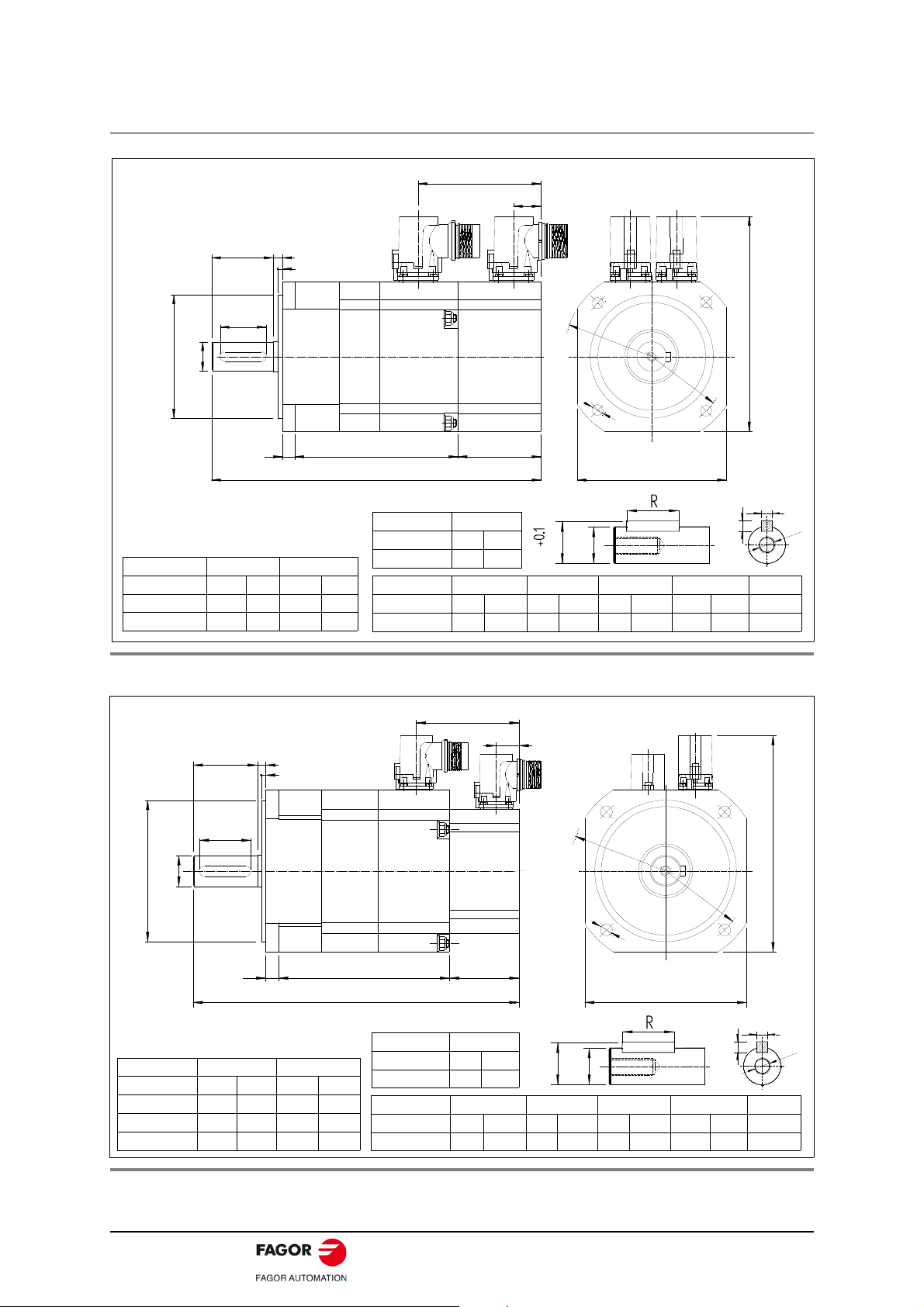
F. 1 Dimensions of FXM1 series motors.
F. 2 Dimensions of FXM3 series motors.
Digital Brushless AC Servo Drive system - Ref.1609 ACSD-11/80
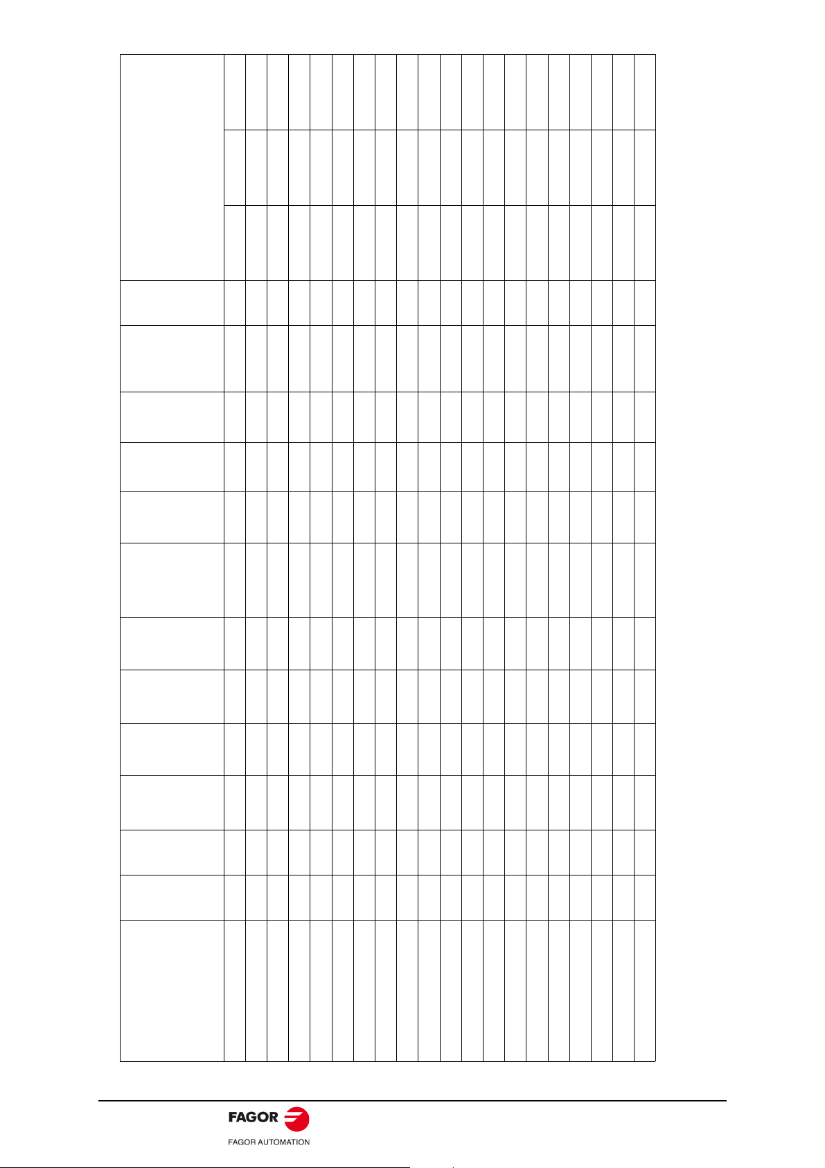
F. 3 Dimensions of FXM5 series motors.
Ø
1
6
5
12
40
Ø130j6
Ø24j6
50±0.25
0
3.5±0.1
LB
WITH BRAKE: LB+28
46
40
1
2
145
Ø
1
9
7
~189
GA
GD
F
S
T
-0.2
FXM5 series
Dimension F GD R GA ST
Units mminmminmminmminmm
FXM5 8 0.31 7 0.27 40 1.58 27 1.07 M8x19
Dimension LB
Units mm in
FXM53 237 9.33
FXM54 272 10.71
FXM55 307 12.09
Dimensions in mm, 1 in = 25.4 mm
C1
C2
~C3
Ø
2
1
5
Ø
2
4
5
15
Ø180j6
Ø32k6
1
5
LB
WITH BRAKE: LB+41
46
50
58
±0.25
0
4±0.1
185
GA
GD
F
S
T
-0.2
+0.5
Dimension C1 C2 C3
Units mm in mm in mm in
Io 23 A (MC 23) 40 1.57 35 1.37 229 9.01
23 A < Io 46 A (MC 46) 50 1.96 40 1.57 236 9.29
FXM7 series
Dimensions in mm, 1 in = 25.4 mm
Dimension F GD R GA ST
Units mminmminmminmminmm
FXM7 10 0.39 8 0.31 50 1.97 35 1.38 M10x22
Dimension LB
Units mm in
FXM73 256 9.33
FXM74 291 10.71
FXM75 326 12.09
FXM76 361 14.21
FXM77 396 15.59
FXM78 431 16.97
F. 4 Dimensions of FXM7 series motors.
ACSD-12/80 Digital Brushless AC Servo Drive system - Ref.1609
Power connector
IP 67
PIN
SIGNAL
A
B
C
D
E
F
U PHASE
V PHASE
W PHASE
GND
BRAKE +
BRAKE -
AMC 23
MC 23
60 (2.36)
40 (1.57)
MOTOR POWER BASE
CONNECTOR
E
A
F
D
C
B
125 (4.92)
110 (4.33)
105 (4.13)
Viewer from outside the motor
MC 23. POWER AIR CONNECTOR. STRAIGHT
AMC 23. POWER AIR CONNECTOR. ANGLED
IP 67
POWER CONNECTORS
Motor connector
MC - Straight
EX. MC - 23
AMC - Angled
Current
23 Amperes
The power connector includes the brake terminals (E, F). A voltage between 22 and 26
V DC releases the shaft. When installing the motor, verify that the brake releases the
shaft completely before turning it for the first time. Connecting the motor windings in the
order indicated on the connector (U, V, W), the shaft will turn clockwise (CWR, Clock
Wise Rotation).
F. 5 MC-23 or AMC-23 power connector. Sales reference. Pinout and dimensions.
Digital Brushless AC Servo Drive system - Ref.1609 ACSD-13/80

Motor feedback connector
62 (2.44)
91 (3.58)
IO. INCREMENTAL TTL ENCODER TAMAWAGA OIH48
IOC-17. MOTOR CONNECTOR
VIEWED FROM OUTSIDE THE MOTOR
A
B
C
D
E
FG
H
I
K
J
P
L
M
N
O
Q
IOC-17
PIN
SIGNAL
A
B
C
D
E
F
A+
A+5 VDC
GND
B+
BG
H
I
J
K
L
Z+
ZPTC
THERMISTOR
PTC THERMISTOR
U+
U-
M
V+
N
V-
O
W+
P
W-
Q
SHIELD+CHASSIS
68 (2.67)
89 (3.50)
SEALING: IP65 STAND
PIN
SIGNAL
1
2
3
4
5
6
REFCOS
+485
PTC THERMIST.
PTC THERMIST.
SIN
REFSIN
7
8
9
10
11
12
-485
COS
CHASSIS
GND
N. C.
+8 VDC
19
8
7
6
5
4
3
2
11
12
10
P
E1. SINCODER STEGMANN SNS50 ENCODER
Pins of 9 and 10 of the connector of the incremental TTL encoder correspond to the
thermistor used to monitor motor overheating.
F. 6 Feedback connector, IOC-17. Incremental TTL encoder (ref. I0). Pinout and di-
mensions.
Pins of 3 and 4 of the SinCos or SinCoder encoder connector correspond to the
thermistor used to monitor motor overheating.
F. 7 Feedback connector, EOC-12. SinCos encoder (ref. A1) and SinCoder encoder
(ref. E1). Pinout and dimensions.
ACSD-14/80 Digital Brushless AC Servo Drive system - Ref.1609
Holding brake
FXM motors have an optional holding brake that applies friction to the shaft. Its purpose
is to immobilize or lock vertical axes, not to brake a moving axis.
Technical data
The characteristics depending on the type of brake are:
T. 5 Technical data of the holding brake.
Motor Holding
torque
Units N·m in·lbf W hp ms V DC kg·cm² kg lbf
FXM1 Mo motor 12 0.016 19/29 22-26 0.38 0.3 0.66
FXM3 Mo motor 16 0.021 20/29 22-26 1.06 0.6 1.32
FXM5 Mo motor 18 0.024 25/50 22-26 3.60 1.1 2.42
FXM7 Mo motor 35 0.047 53/97 22-26 31.80 4.1 9.03
Nota. The maximum speed is 10000 rev/min, for all of them except for the brake that
may be used on the FXM7 series that is 8000 rev/min.
WARNING. NEVER use this holding brake to stop a moving axis!
WARNING.
The holding brake must never exceed its maximum turning speed.
Power
consumption
ON/OFF
time
Releasing
voltage
margin
Inertia Mass
approx.
A voltage between 22 and 26 V DC releases the shaft. Make sure that
no voltage over 26 V DC is applied that prevents the shaft from turning.
When installing the motor, make sure that the holding brake fully
releases the shaft before making it turn for the first time.
Digital Brushless AC Servo Drive system - Ref.1609 ACSD-15/80
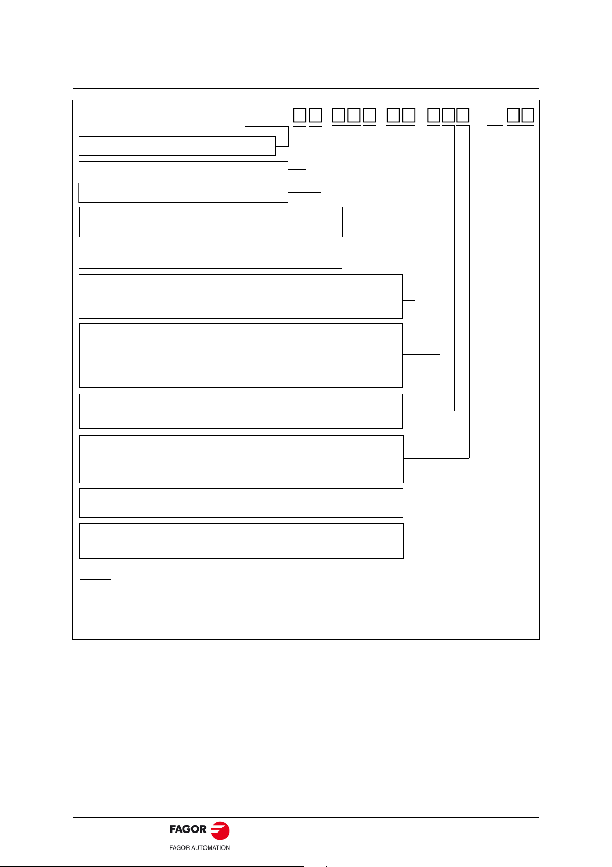
Sales reference
0
Without fan
12
1200 rev/min
20
2000 rev/min
30
3000 rev/min
40
4000 rev/min
FXM . . .
- X
FAGOR SYNCHRONOUS MOTOR
SIZE 1, 3, 5, 7
LENGTH 1, 2, 3, 4, 5
RATED
SPEED
WINDING
FEEDBACK
TYPE
I0
Incremental encoder (2500 ppt)
A1
Absolute multi-turn SinCoder encoder (1024 ppt)
E1
SinCoder encoder (1024 ppt)
FLANGE &
SHAFT
0
IEC Standard
BRAKE
OPTION
0
Without brake
FAN
F
220 V AC
A
1
With Standard fan
1
With standard brake (24 V DC)
1
Keyless shaft
8
NEMA standard (USA)
9
Special
9
With special fan
SPECIAL
CONFIGURATION
X
SPECIFICATION
01
ZZ
Only when it has a special configuration (X) !
400 V AC
Notes.
Encoders with reference:
I0, only available on FXM servomotors, “F” winding.
E1/A1, only available on FXM servomotors, “A” winding.
ACSD-16/80 Digital Brushless AC Servo Drive system - Ref.1609
BRUSHLESS AC MOTORS, FKM
FKM synchronous servo motors are AC brushless
with permanent magnets.
They are ideal for any application requiring great
positioning accuracy. They have a uniform output
torque, high reliability and low maintenance.
They are designed to meet the IP 64 protection
standard and, therefore, they are immune to
liquid and dirt.
FKM2 FKM4 FKM6
IP 64 means that is protected against dust and against water jets. They have a
temperature sensor to monitor the internal temperature. They also carry an optional
electromechanical holding brake. They have rotating power and feedback connectors.
The F class isolation on the motor maintains the dielectric properties as long as the work
temperature stays below 150°C/302°F.
IM B5
IM V3
IM V1
Introduction
General characteristics
T. 6 FKM servomotors. General characteristics.
Excitation Permanent rare earth magnets (Nd-Fe-B)
Temperature sensor
Shaft end Cylindrical keyless (optional with keyway)
Mounting Face flange with through holes
Mounting method IM B5 - IM V1 - IM V3 (as recommended by IEC-34-3-72)
Mechanical tolerances Normal class (meets IEC-72/1971)
Balancing Class N (R optional) (DIN 45665) half-key balancing
Roller bearings’ life 20000 hours
Noise DIN 45635
Vibration resistance Withstands 1g along the shaft and 3g sideways (g=9.81m/s²)
Electrical insulation Class F (150°C/302°F)
Insulation resistance 500 V DC, 10 M or greater
Dielectric rigidity 1500 V AC, one minute
Protection degree General: Standard IP 64. Shaft: Standard IP 64, IP 65 with oil seal
Storage temperature -20°C/+80°C (-4°F/+176°F)
Ambient temperature 0°C/+40°C (+32°F/+104°F)
Working ambient From 20% to 80% (non condensing)
Holding brake Optional. See technical data ·holding brake·
Feedback
Thermistor PTC KTY84-130
Thermistor PTC Pt1000 (shortly)
I0 Incremental TTL encoder ·2500 ppt·
E3/A3 Sinusoidal encoder / Multi-turn abs. encoder ·1024 ppt·
Meaning of the
codes of the
mounting method
Digital Brushless AC Servo Drive system - Ref.1609 ACSD-17/80
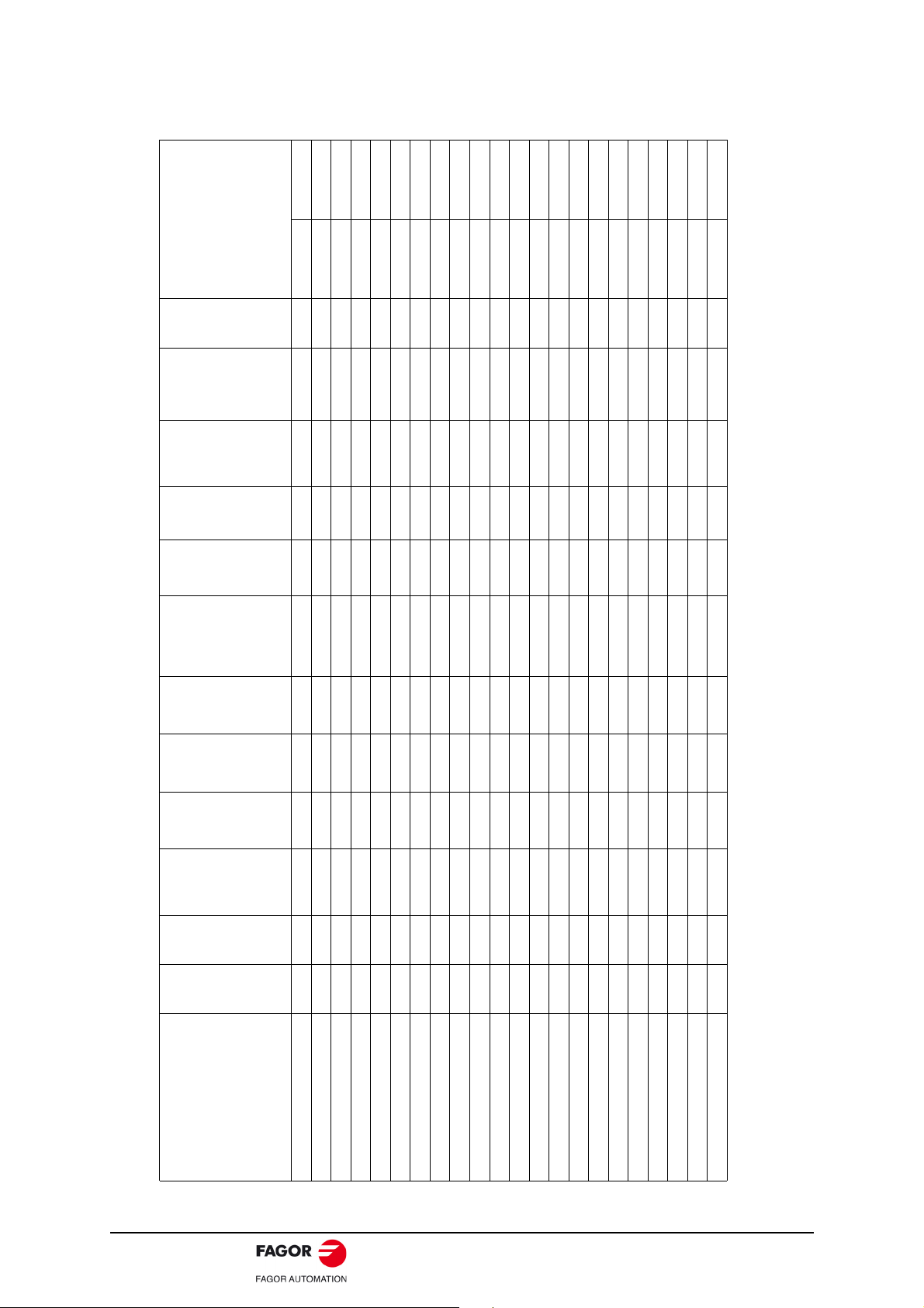
T. 7 Technical data of non-ventilated synchronous FKM motors with “A” winding (400 V AC).
Non-ventilated
motors
Stall torque
Stall peak
torque
Rated
speed
Stall
current
Peak
current
Calculation
power
Torq u e
constant
Acceleration
time
Inductance
per phase
Resistance
per phase
Inertia
1
Mass
2
Drive
peak torque
Mo Mp nN Io Imax Pcal kt tac L R J M ACSD-08H ACSD-16H
N·m N·m rpm A A kW N·m/A ms mH
kg·cm²
kg N·m N·m
FKM21.60A.. 1.7 7 6000 2.8 11 1.1 0.60 14.4 7.70 2.600 1.6 4.2 4.8 7.0
FKM22.30A.. 3.2 13 3000 2.4 10 1.0 1.33 7.0 16.00 3.950 2.9 5.3 10.4 13.0
FKM22.50A.. 3.2 13 5000 4.0 16 1.7 0.80 11.7 5.80 1.400 2.9 5.3 6.4 12.8
FKM22.60A.. 3.2 13 6000 4.5 18 2.0 0.71 14.0 4.60 1.100 2.9 5.3 11.3
FKM42.30A.. 6.3 25 3000 4.6 19 2.0 1.36 10.7 8.60 1.450 8.5 7.8 21.7
FKM42.45A.. 6.3 25 4500 6.9 28 3.0 0.91 16.0 3.90 0.675 8.5 7.8 14.5
FKM42.60A.. 6.3 25 6000 8.5 34 3.9 0.74 21.3 2.60 0.450 8.5 7.8 11.8
FKM43.20A..
9.0 36 2000 3.9 15.7 1.88 2.30 9.7 14.5 1.720 16.7 11.7 18.4 36.0
FKM43.30A.. 9.0 36 3000 6.2 25 2.82 1.45 14.5 6.2 0.755 16.7 11.7 23.2
FKM43.40A.. 9.0 36 4000 9.4 38 3.77 0.95 19.4 2.4 0.315 16.7 11.7 15.2
FKM44.20A.. 11.6 47 2000 4.6 19 2.4 2.52 7.4 14.51 1.720 16.7 11.7 40.3
FKM44.30A.. 11.6 47 3000 8.2 33 3.6 1.41 11.2 4.20 0.540 16.7 11.7 22.5
FKM44.30A...2 11.6 47 3000 7.0 28 3.6 1.65 11.1 6.16 0.755 16.7 11.7 26.4
FKM62.30A.. 8.9 35 3000 7.1 28 2.8 1.25 14.4 7.20 0.770 16.0 11.9 20.0
FKM62.40A.. 8.9 35 4000 9.3 37 3.7 0.95 19.1 4.10 0.440 16.0 11.9 15.3
FKM63.20A.. 12.5 51 2000 5.3 21.3 2.6 2.35 12.1 13.2 0.935 29.5 17.1 37.6
FKM63.30A.. 12.5 51 3000 10.3 40.6 3.9 1.21 18.1 3.8 0.280 29.5 17.1 19.3
FKM64.20A..
16.5 66 2000 6.5 26 3.4 2.53 9.3 13.16 0.935 29.5 17.1 40.6
FKM66.20A..
23.5 94 2000 10.5 42 4.9 2.23 9.5 4.60 0.315 43.0 22.3 35.8
FKM66.20A...2
23.5 94 2000 9.4 37 4.9 2.50 9.5 8.82 0.410 43.0 22.3 40.0
1. Motor inertia without holding brake.
2. Motor mass without holding brake.
NOTE. In the combinations shown in bold letters, the drive will limit its peak current automatically so as not to damage the motor.
ACSD-18/80 Digital Brushless AC Servo Drive system - Ref.1609
T. 8 Technical data of non-ventilated synchronous FKM motors with “F” winding (220 V AC).
Non-ventilated
motors
Stall torque
Stall peak
torque
Rated
speed
Stall
current
Peak
current
Calculation
power
Torq u e
constant
Acceleration
time
Inductance
per phase
Resistance
per phase
Inertia
1
Mass
2
Drive
peak torque
Mo Mp nN Io Imax Pcal kt tac L R J M ACSD-10L ACSD-20L ACSD-30L
N·m N·m rpm A A kW N·m/A ms mH kg·cm² kg N·m N·m N·m
FKM21.60F.. 1.7 7 6000 4.7 19 1.1 0.36 14.4 2.6 0.885 1.6 4.2 3.6 7.0 -
FKM22.30F.. 3.2 13 3000 4.5 18 1.0 0.74 7.0 4.6 1.100 2.9 5.3 7.4 13.0 -
FKM22.50F.. 3.2 13 5000 7.2 29 1.7 0.45 11.7 1.7 0.425 2.9 5.3 3.6 9.0 13.0
FKM42.30F.. 6.3 25 3000 8.5 34 2.0 0.74 10.7 2.6 0.450 8.5 7.8 - 14.8 22.2
FKM42.45F.. 6.3 25 4500 12.4 50 3.0 0.51 16.0 1.2 0.210 8.5 7.8 - 18.2 25.0
FKM43.30F.. 9.0 36 3000 13.8 55.4 2.8 0.65 14.5 1.2 0.150 16.7 11.7 - - 19.5
FKM44.30F.. 11.6 47 3000 15.6 62 3.6 0.74 11.2 1.2 0.150 16.7 11.7 - - 22.2
FKM62.30F.. 8.9 35 3000 13.1 52 2.8 0.68 14.4 2.1 0.225 16.0 11.9 - - 20.4
FKM62.40F.. 8.9 35 4000 16.4 66 3.7 0.54 19.1 1.3 0.180 16.0 11.9 - - 16.2
FKM63.20F.. 12.5 51 2000 11.7 46.6 2.6 1.06 12.1 2.7 0.205 29.5 17.1 - - 31.8
FKM63.30F.. 12.5 51 3000 16.6 66.4 3.9 0.75 18.1 1.3 0.100 29.5 17.1 - - 22.5
FKM64.20F.. 16.5 66 2000 14.3 57 3.4 1.15 9.35 2.7 0.205 29.5 17.1 - - 34.5
FKM64.30F.. 16.5 66 3000 20.0 80 5.1 0.82 14.0 1.3 0.145 29.5 17.1 - - 24.6
FKM66.20F.. 23.5 94 2000 19.2 76.8 4.9 1.22 9.57 0.8 0.135 43.0 22.3
--
36.6
1. Motor inertia without holding brake.
2. Motor mass without holding brake.
NOTE. In the combinations shown in bold letters, the drive will limit its peak current automatically so as not to damage the motor.
Digital Brushless AC Servo Drive system - Ref.1609 ACSD-19/80
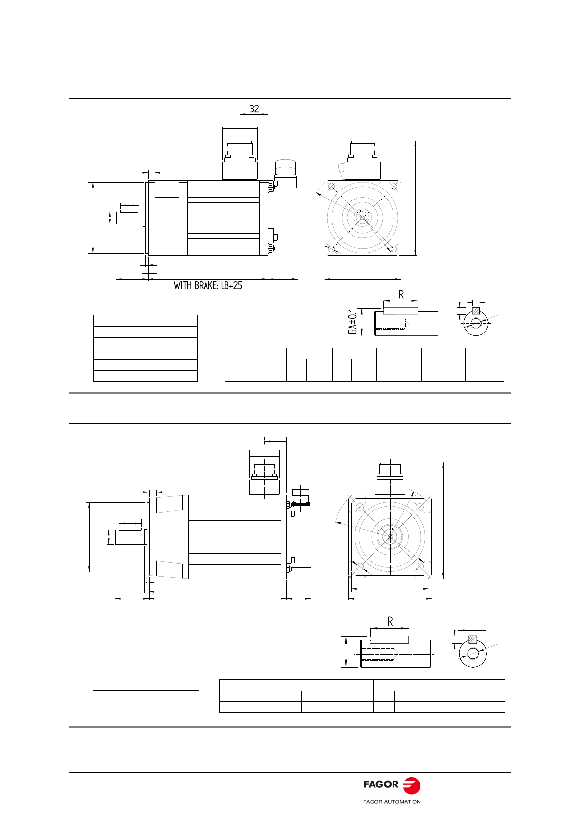
Dimensions
80
18
40±0.1
0
3±0.1
Ø80j6
Ø19j6
30
8 54LB
L
97
139.5
7
Ø
1
0
0
Ø
1
1
5
Dimensions in mm, 1 in = 25.4 mm
FKM2 series
D
GA
GD
F
S
T
-0.2
Dimension LB L
Units mm in mm in
FKM21 106 4.17 208 8.19
FKM22 130 5.11 232 9.13
Dimension F GD R GA ST
Units mm in mm in mm in mm in mm
FKM2 6 0.23 6 0.23 30 1.18 21.5 0.84 M6x16
Dimension ØD j6
Unidades mm in
FKM2 19 0.74
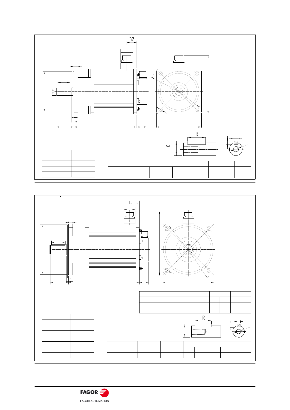
80
18
50±0.1
0
3.5±0.1
Ø24j6
Ø110j6
40
10
54LB
L
126
168.5
9
Ø
1
3
0
Ø
1
5
0
Dimensions in mm, 1 in = 25.4 mm
FKM4 series
Dimension LB L
Units mm in mm in
FKM42 133 5.23 247 9.72
FKM43 175 6.88 289 11.38
FKM44 175 6.88 289 11.38
Dimension F GD R GA ST
Units
mm in mm in mm in mm in mm
FKM4 8 0.31 7 0.27 40 1.57 27 1.06 M8x19
Dimension ØD j6
Units mm in
FKM4 24 0.94
D
GA
GD
F
S
T
-0.2
0
F. 8 Dimensions of FKM2 series motors.
F. 9 Dimensions of FKM4 series motors.
ACSD-20/80 Digital Brushless AC Servo Drive system - Ref.1609
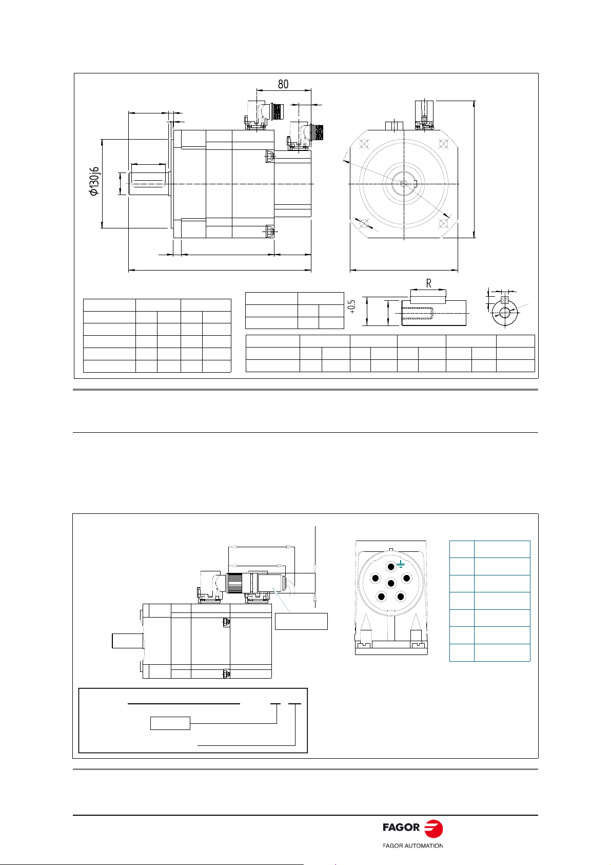
F. 1 0 Dimensions of FKM6 series motors.
200.5
1
2
0
3.5±0.1
50
Ø32k6
Ø
1
6
5
Ø
1
9
0
12
54LB
L
158
18
58±0.25
Dimension LB L
Units mm in mm in
FKM62 136 5.35 260 10.24
FKM63 172 6.77 296 11.65
FKM64 172 6.77 296 11.65
FKM66 208 8.18 332 13.07
Dimensions in mm, 1 in = 25.4 mm
FKM6 series
Dimension F GD R GA ST
Units mm in mm in mm in mm in mm
FKM6 10 0.39 8 0.31 50 1.96 35 1.37 M10x22
Dimension ØD k6
Units mm in
FKM6 32 1.26
D
GA
GD
F
S
T
-0.2
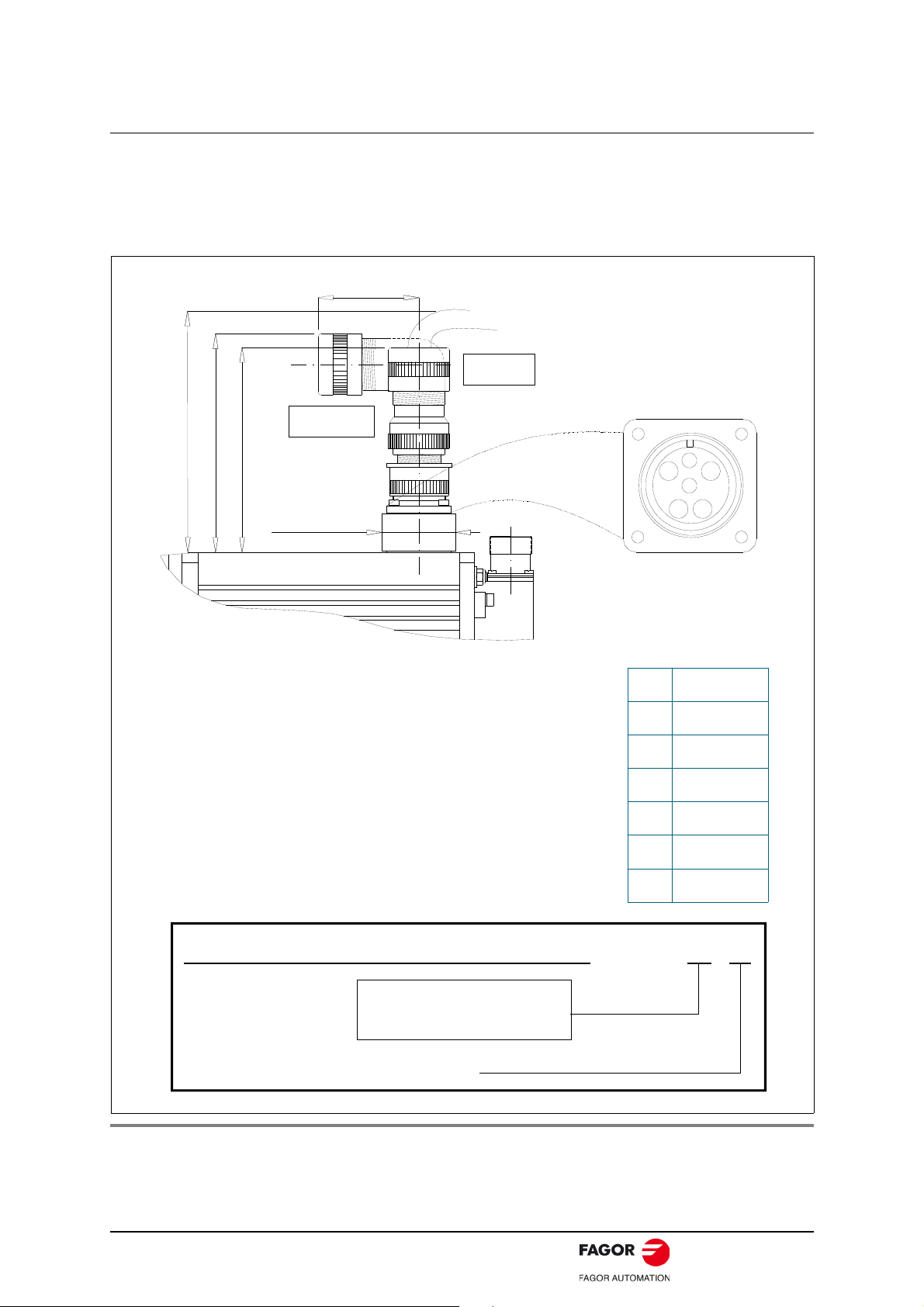
MOTOR POWER BASE
CONNECTOR
PIN
SIGNAL
1
2
6
3
4
5
U PHASE
V PHASE
W PHASE
GND
BRAKE +
BRAKE -
2
1
5
6
4
97 (3.82)
80 (3.15)
27 (1.06)
MC-20/6
IP 65
Viewed from outside the motor
POWER CONNECTOR
Power cable
connector
MC - 20/6
E.g. MC - 20/6
Current
20 Amperes
Power connector
It includes the connectors of the brake itself (pins 4 and 5). A voltage between 22 and
26 V DC releases the shaft. When installing the motor, verify that the brake releases the
shaft completely before turning it for the first time. Connecting the motor windings in the
order indicated on the connector (U, V, W), the shaft will turn clockwise (CWR, Clock
Wise Rotation).
F. 11 Power connector, MC-20/6. Sales reference, pinout and dimensions.
Digital Brushless AC Servo Drive system - Ref.1609 ACSD-21/80
Motor feedback connector
62
(2.44)
91
(3.58)
IOC-17
SEALING: IP 65 STANDARD
U+
U-
13
V+
14
V-
15
W+
16
W-
17
SHIELD+CHASSIS
PIN
SIGNAL
1
2
3
4
5
6
A+
A-
+5 VDC
GND
B+
B7
8
9
10
11
12
Z+
Z-
TEMP -
TEMP +
1
2
3
4
5
6
7
8
9
10
11
12
13
14
15
16
17
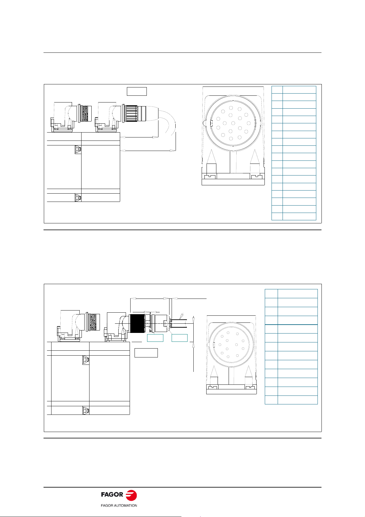
IO. INCREMENTAL TTL ENCODER TAMAWAGA OIH 48
IOC-17. MOTOR CONNECTOR
VIEWED FROM OUTSIDE THE MOTOR
Ø8.5 (0.33)
26
(1.02)
c.a. 3
(0.11)
SW23
SW22
54
(2.12)
0.7MAX
EOC-12
IP 65 STAND.
PIN SIGNAL
1
2
3
4
5
6
REFCOS
+ 485
TEMP TEMP +
SIN
REFSIN
7
8
9
10
11
12
- 485
COS
CHASSIS
GND
N. C.
+8 VDC
1
2
3
45
6
11
7
8
9
10 12
E3. ENCODER SINCOS STEGMANN SRM
EOC-12. MOTOR CONNECTOR
VIEWED FROM OUTSIDE THE MOTOR
A3. ENCODER SINCOS STEGMANN SRS
Pins 9 and 10 on the connector of the TTL incremental encoder (ref. I0) correspond to
the thermal sensor of the motor that monitors its heating. Note that the PTC KTY84-130
thermistor has polarity, (pin 9 - / pin10 +), while the PTC Pt1000 does not.
F. 1 2 Feedback connector, IOC-17. TTL incremental encoder (ref. I0). Pinout and
dimensions.
Pins 3 and 4 on the connector of the SinCos encoder (refs. E3/A3) correspond to the
thermal sensor of the motor that monitors its heating. Note that the PTC KTY84-130
thermistor has polarity(pin 3 - / pin 4 +), while the PTC Pt1000 does not.
F. 1 3 Feedback connector, EOC-12. SinCos encoder (refs. E3/A3). Pinout and
ACSD-22/80 Digital Brushless AC Servo Drive system - Ref.1609
dimensions.
Holding brake
FKM motors have an optional holding brake that applies friction to the shaft. Its purpose
is to immobilize or lock vertical axes, not to brake a moving axis.
Technical data
Its main characteristics depending on the type of brake are:
T. 9 Technical data of the holding brake.
Motor Holding
torque
Units N·m lbf·ft W hp ms V DC kg·cm² kg lbf
FKM2 4.5 3.32 12 0.016 7/35 22-26 0.18 0.30 0.66
FKM4 9.0 6.64 18 0.024 7/40 22-26 0.54 0.48 1.06
FKM6 18.0 13.28 24 0.032 10/50 22-26 1.66 0.87 1.92
Note. Maximum speed for all ot them is 10000 rev/min.
WARNING. NEVER use this holding brake to stop a moving axis.
WARNING.
The holding brake must never exceed its maximum turning speed.
Voltage between 22 and 26 V DC releases the shaft. Make sure that no
voltage over 26 V DC is applied that prevents the shaft from turning.
When installing the motor, make sure that the brake fully releases the
shaft before making it turn for the first time.
Power
consumption
ON/OFF
time
Range of
releasing
voltage
Inertia Mass
approx.
Digital Brushless AC Servo Drive system - Ref.1609 ACSD-23/80
Sales reference
0
Standard
1
Electro-ventilated
8
Low inertia
9
Low inertia and electro-ventilated
(future)
20
2000 rev/min
45
4500 rev/min
30
3000 rev/min
50
5000 rev/min
FKM . .
MOTOR SERIES
SIZE 2, 4, 6
LENGTH 1, 2, 3, 4, 6
RATED
SPEED
WINDING
A
400 V AC
FEEDBACK TYPE
A3
Multi-turn absolute sinusoidal 1Vpp ·1024 ppt· (taper shaft)
E3
Sinusoidal 1Vpp encoder ·1024 ppt· (taper shaft)
I0
TTL incremental encoder ·2500 ppt·
FLANGE
AND
SHAFT
0
With keyway (half-key balancing)
BRAKE
OPTION
0
Without brake
1
With standard brake · 24 V DC ·
2
With extra brake · 24 V DC ·
FAN AND
INERTIA
OPTION
F
220 V AC
1
Cylindrical (with no keyway)
40
4000 rev/min
60
6000 rev/min
01 ... 99
SPECIFICATION
Only when it has a special configuration “K”
2
Shaft with keyway and seal
3
Keyless shaft with seal
9
Special configuration
- K
.
.
None
Standard
2
Optimized for ACSD-16H
3
Small size
WINDING
OPTION
0/none
PTC KTY84
1
TEMPERATURE
SENSOR
EXTRAS
-
None
K
Special configuration
U
NRTLSAFET certification (future)
PTC Pt1000 (future)
Notes.
Encoders with reference:
I0, only available on FKM2/4/6 servomotors, “F” winding.
E3/A3, only available on FKM2/4/6 servomotors, “A” winding.
The type of temperature sensor that is incorporated in the servomotor is identified in the corresponding
field shown in the figure and is stored in the memory of the feedback device.
ACSD-24/80 Digital Brushless AC Servo Drive system - Ref.1609
COMPACT SERVO DRIVE, ACSD
Introduction
ACSD is a compact speed servo drive family for controlling
synchronous AC brushless servomotors.
It has two series depending on the supply voltage they can be
connected to: Hence, we will refer to:
ACSD (H series) if the power supply voltage is 400 V AC
ACSD (L series) if the power supply voltage is 220 V AC
where each of them will have the following models depending on
their peak current:
For the “ACSD-xxH” series:
ACSD-04H ACSD-08H ACSD-16H
with peak currents of 4, 8 and 16 A.
For the “ACSD-xxL” series:
ACSD-05L ACSD-10L ACSD-20L ACSD-30L
with peak currents of 5, 10, 20 and 30 A.
General characteristics
Their main characteristics are:
Three phase power supply.
Dynamic braking in case of mains failure.
PWM IGBTs.
2500-line incremental TTL encoder feedback or 1Vpp sinusoidal
encoder.
CAN field bus communication interface.
Two logic inputs to control the motor (speed enable and drive
enable).
One programmable logic input.
One programmable logic output.
“On-line” parameter editing.
Typical protections in velocity drives.
RS-232 communication (only for uploading software).
CANopen communication protocol.
Digital Brushless AC Servo Drive system - Ref.1609 ACSD-25/80
 Loading...