

Page 1
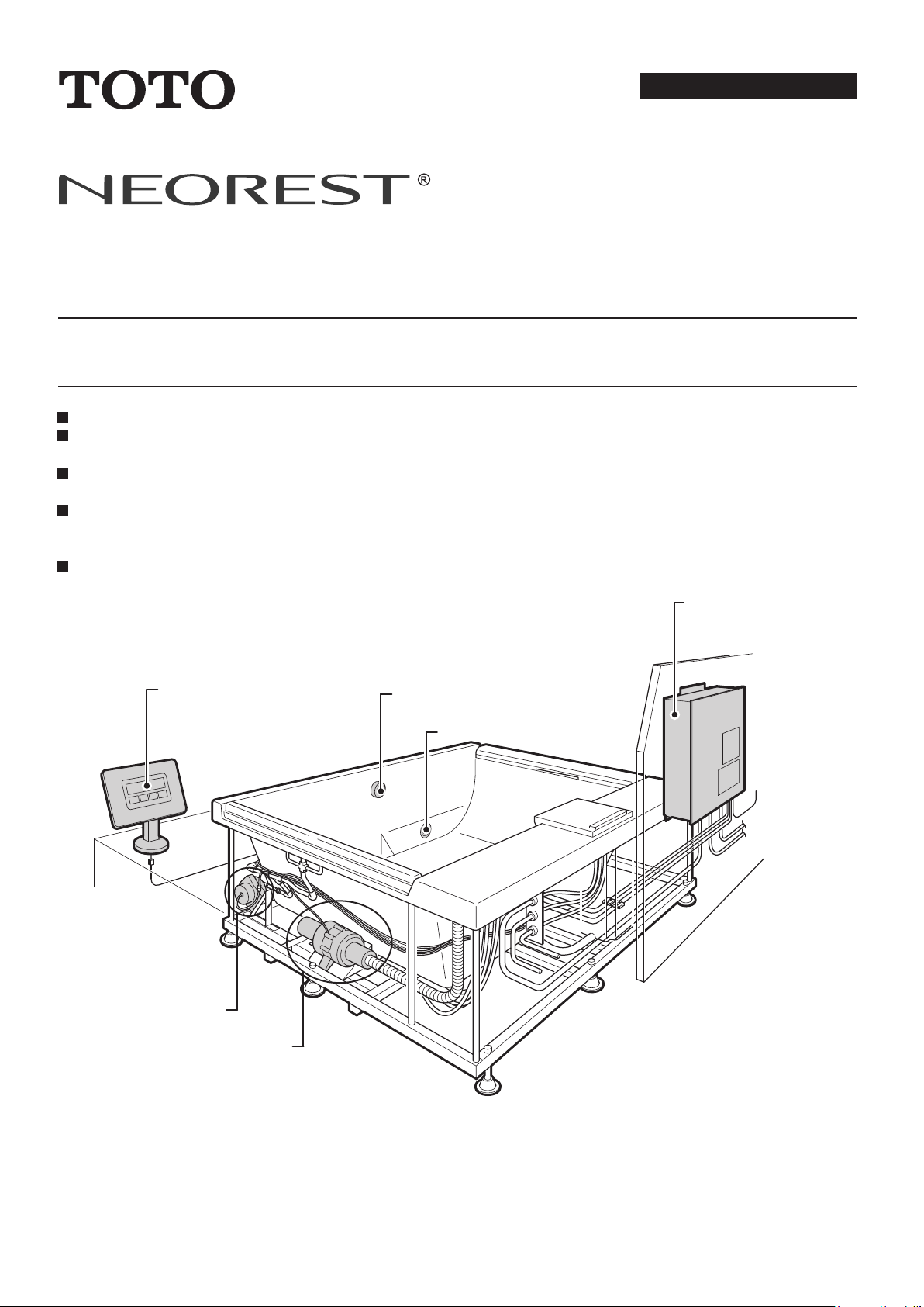
Function module
Controller stand
Overflow fitting
Pump
Blower
Underwater illumination
Installation Manual
AIRBATH™
Please install the product properly, in accordance with the descriptions in this manual so that full use can be made
of the product's functions.
After installing the product, please tell the customer how to use the product fully.
Thank you for choosing to use the Toto NEOREST®AIRBATH™ on this occasion.
Please install the product properly, in accordance with the descriptions in this manual so that
full use can be made of the product's functions.
Please be sure to discuss the procedures for the bathtub installation, the various phases of
construction for the function module, and the electrical and plumbing work before starting.
After completing the construction, please explain the operation to the customer and give this
Installation Manual and the accompanying "Instruction Manual" to the customer.
Note also: Please be sure to fill in the required items in the warranty.
Please be aware that the parts numbers listed in the Installation Manual may be revised.
Page 2

Page 3

Table of contents
1. IMPORTANT SAFETY INSTRUCTIONS .....................................................4 ~ 7
1-1 Bathtub............................................................................................................................5
1-2 Function module..............................................................................................................6
2. Contents of set ..........................................................................................8 ~ 9
2-1 Bathtub ............................................................................................................................8
2-2 Cables..............................................................................................................................8
2-3 Controller Stand...............................................................................................................9
2-4 Function module..............................................................................................................9
3. Dimension Drawings and Specifications ............................................10 ~ 12
3-1 Bathtub, Controller stand and Function Module............................................................10
3-2 List of Specifications ....................................................................................................12
4. Installation Procedure ....................................................................................13
5. Installation Precautions .........................................................................14 ~ 16
5-1 Bathtub ..........................................................................................................................14
5-2 Function module............................................................................................................15
5-3 Clean-up Shower Installation Conditions ......................................................................16
5-4 Function module installation locations ..........................................................................17
6. Installation requirements .......................................................................18 ~ 39
6-1 Building a base for the bathtub ~ seating the bathtub ..................................................18
(1) Building a base .............................................................................................................................18
(2) Plumbing and connecting the drain pipes ....................................................................................18
(3) Seating the bathtub.......................................................................................................................19
6-2 Finishing ........................................................................................................................20
(1) Fixing the bathtub in place............................................................................................................20
(2) Plumbing and connecting the hot/cold pipes and the fill-tub pipe ................................................20
(3) Connecting the cables ..................................................................................................................20
(4) Finishing the tiles ..........................................................................................................................21
6-3 Controller stand installation ...........................................................................................22
(1) Marking the pilot hole, drilling the hole and installing the plug.....................................................22
(2) Attach the base .............................................................................................................................23
(3) Install the slip ring .........................................................................................................................24
(4) Controller stand installation ..........................................................................................................25
6-4 Function module installation..........................................................................................26
(1) Advance preparation.....................................................................................................................26
(2) Function module installation .........................................................................................................26
(3) Positioning of holes for function module installation screws ........................................................27
(4) Function module installation .........................................................................................................28
(5) Plumbing the equipment ...............................................................................................................28
(6) Inspecting for leaks in the fill-tub plumbing ..................................................................................29
(7) Plumbing the hot, cold and fill-tub pipes.......................................................................................30
(8) Electrical work...............................................................................................................................31
6-5 Confirmation and trial operation ....................................................................................33
3
Page 4
1. IMPORTANT SAFETY INSTRUCTIONS
Please be sure to
observe the
warning and
caution symbols!
READ AND FOLLOW ALL INSTRUCTIONS. SAVE THIS INSTRUCTION with your instruction
●
●
manual.
INSTALL TO PERMIT ACCESS FOR SERVICING.
INSTALL THIS UNIT IN ACCORDANCE WITH THE NATIONAL ELECTRICAL CODE (NEC) NFPA 70 AND CANADIAN
ELECTRICAL CODE, PART 1.
Please read these "Important safety instructions" carefully before beginning the installation work and install the product
correctly.
This Installation Manual has a number of different symbols intended to allow proper and safe installation of the product, to
prevent harm to the end user, to prevent damage to property and to prevent harm to construction workers. These symbols
have the following significance.
Symbol
Warning
Caution
The following symbols can be found in the Installation Manual or on the product and are intended to help the construction
worker install the product safely and properly. Please read the descriptions carefully and install the product correctly.
Symbol
Indicates "prohibited" activity that must not take place.
Indicates "required" activity that must take place.
After completing the installation, please check for safety problems such
as loose fittings or leaks.
The Instruction Manual that is packed with the product is a valuable
source of product information to help the end user use the product
safely and correctly. Please take good care of it and keep it from getting
lost or soiled. After the construction is complete, please give the manual
to the end user or the construction superintendent.
This symbol indicates that errant handling after disregarding this symbol could result in death
or serious personal injury.
This symbol indicates that errant handling after disregarding this symbol could result in
personal injury or cause physical damage.
Meaning
Meaning
4
Page 5
1-1 Bathtub
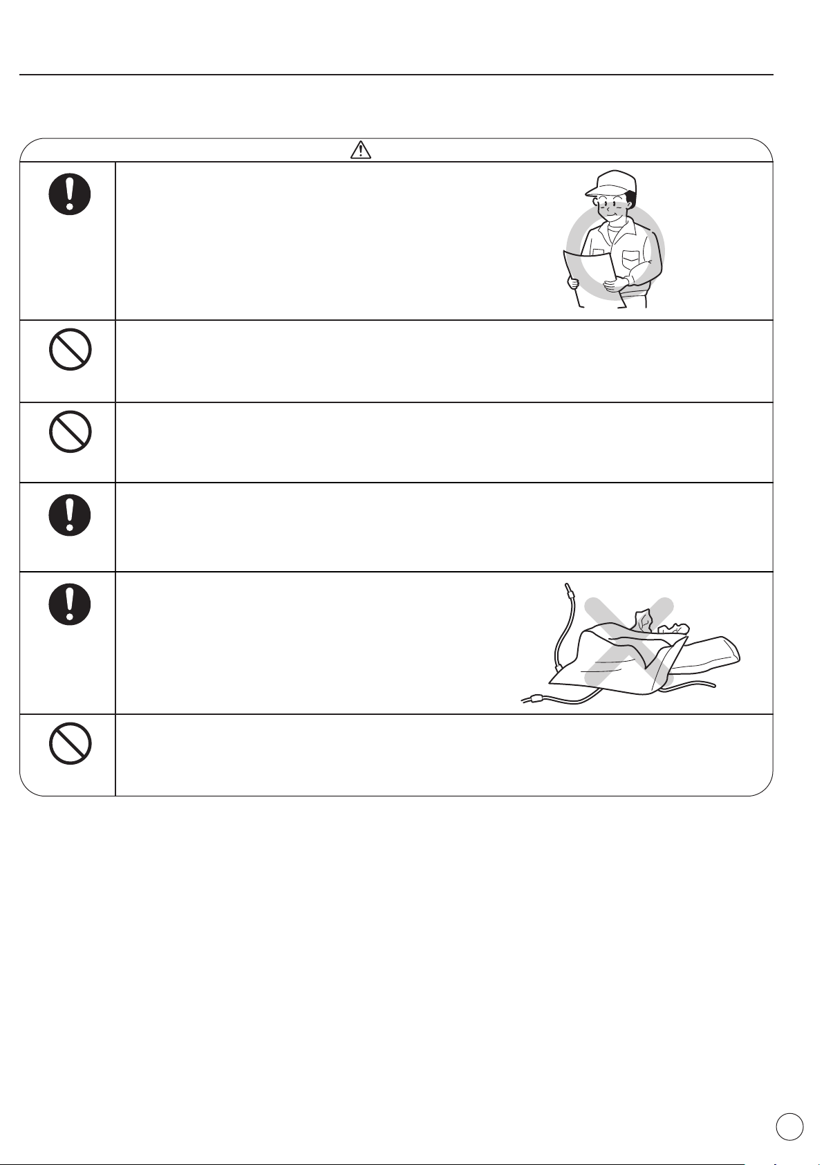
Install the product securely, in accordance with the
Installation Manual.
Always do this
Improper installation can cause leaks that damage or
ruin household property.
Do not drop or strike the bathtub with hard objects.
Warning
Prohibited
Prohibited
Always do this
Always do this
Prohibited
Doing so could crack or scratch the bathtub or cause leaks that damage or ruin household property.
Do not stand on bathtub while working.
Doing so could cause one to slip and fall or could otherwise damage the product.
Install the drainage pipes securely, in accordance with
the procedure.
Improper installation could lead to leaks that damage
or ruin household property.
After opening the box, please immediately dispose of
unneeded packaging.
Wooden frames, nails, cardboard or sealing straps
could cause injury.
Additionally, children or pets might put vinyl bags over
their heads, leading to unanticipated accidents.
Do not install on or near gas, kerosene or other combustible or flammable substances. Otherwise a fire
could result.
5
Page 6
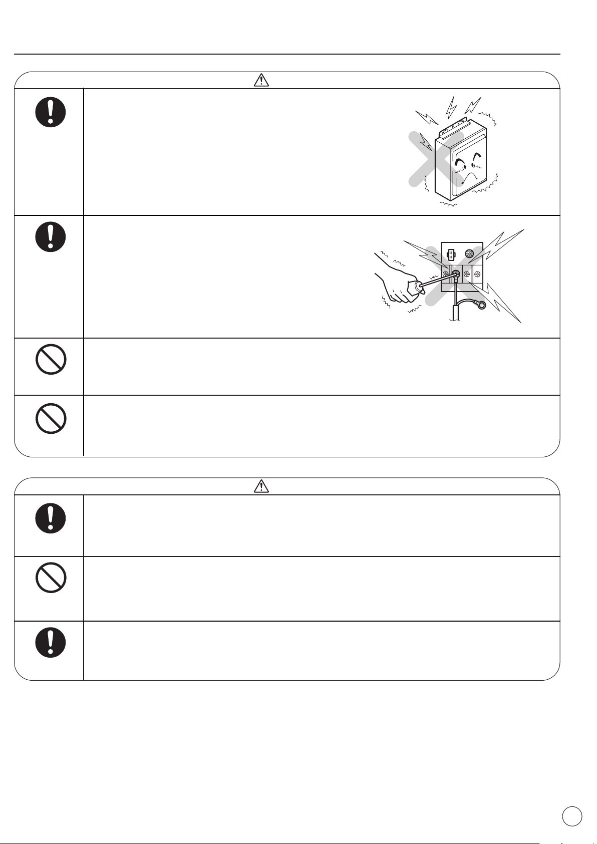
1-2 Function module
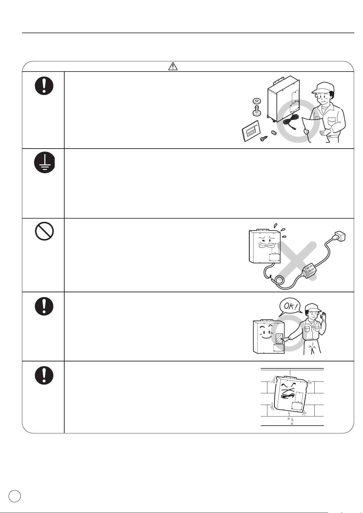
Install securely, in accordance with the Installation
Manual.
Always do this
Improper installation can lead to electric shocks or fire.
Additionally, it could cause water leaks that damage or
ruin household property.
Be sure to have a qualified individual (certified electrician) carry out all electrical work in accordance
with the relevant laws and regulations.
Warning
Connect Ground
Prohibited
Always do this
Improper work can lead to problems or short circuits.
All electrical connections must be in accordance with local codes, ordinances, and the National
Electrical Code (NEC).
If you are unfamiliar with methods of installing electrical wiring and appliances, you should secure the
services of a qualified licensed electrician.
Do not modify the power supply cord, use it with an
extension cord or combine it with other equipment
using multiple plugs.
Doing so could lead to shocks, overheating or fire.
After the installation, test the ground fault circuit
interrupter (GFCI) protecting this appliance and
periodically check it in accordance withe the
manufacturer's instructions.
An improperly functioning GFCI could lead to electric
shock or fire.
6
Always do this
Be sure that the equipment is installed in a stable
place with sufficient load-bearing strength, as set forth
in the Installation Manual.
Improper installation could cause the equipment to fall
or topple over, causing injury.
Page 7
Always do this
Always do this
Prohibited
Warning
When installing the function module using a metal lath
or wire lath support, be certain not to connect the
function module and support electrically.
Doing so could lead to electric shock, overheating or
fire.
CAUTION: To reduce the risk of electrical shock
disconnect power before servicing from the supply
circuit.
Do not install on or near gas, kerosene or other combustible or flammable substances.
Otherwise a fire could result.
Prohibited
Always do this
Prohibited
Always do this
Do not install in locations with high humidity, such as bathing areas or where water might pool.
Otherwise product problems or electric shock could result.
Warning
Always implement the countermeasures for preventing freezing.
It is possible that the pipes could freeze, rupturing the pipes or equipment.
Use no water other than standard tap water.
The use of well water could cause corrosion, which could lead to leaks.
If installing the product in a location where damage from water leaking from the function module is
anticipated, be sure to waterproof the floor.
If there were to be a leak, it could damage the floor or floors below.
7
Page 8
2. Contents of set
After unpacking the product, please confirm the numbers of parts as shown below.
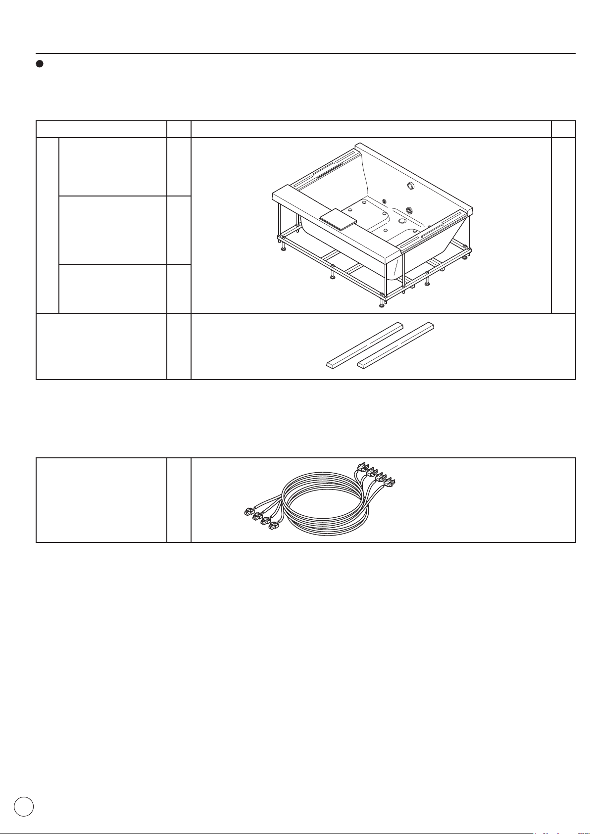
2-1 Bathtub
Part Name Qty Shape of Bathtub Qty
Installation Manual 3
Owner's Manual 3
Cleaning tool
Headrests
2-2 Cables
Junction Cables 3
1
1
2
<Breakdown>
*Power supply junction cable
*Signal junction cable
*Air blower junction cable
8
Page 9
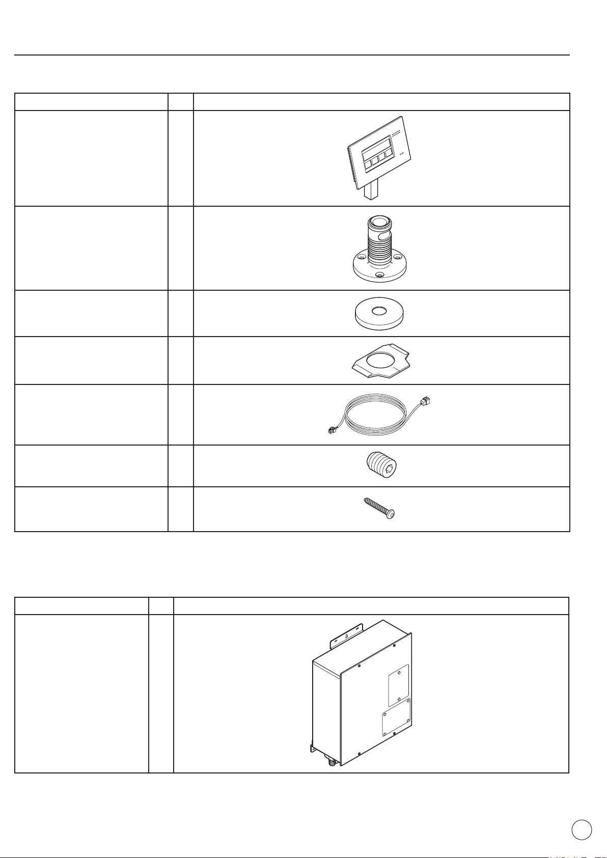
2-3 Controller stand
Product Name Qty
Controller stand assembly 1
Base assembly 1
Base cover 1
Slip ring assembly 1
Controller splitter cord 1
Set screw with hexagonal hole
M4 x 4 long
Phillips head tapping screw
4 x 30 (holds base in place)
(with O-Ring safety sheet)
(Slip Ring inside)
2
3
(1 Spare)
2-4 Function module
Part Name Qty
Function Module
(including mounting
hardware)
1
9
Page 10
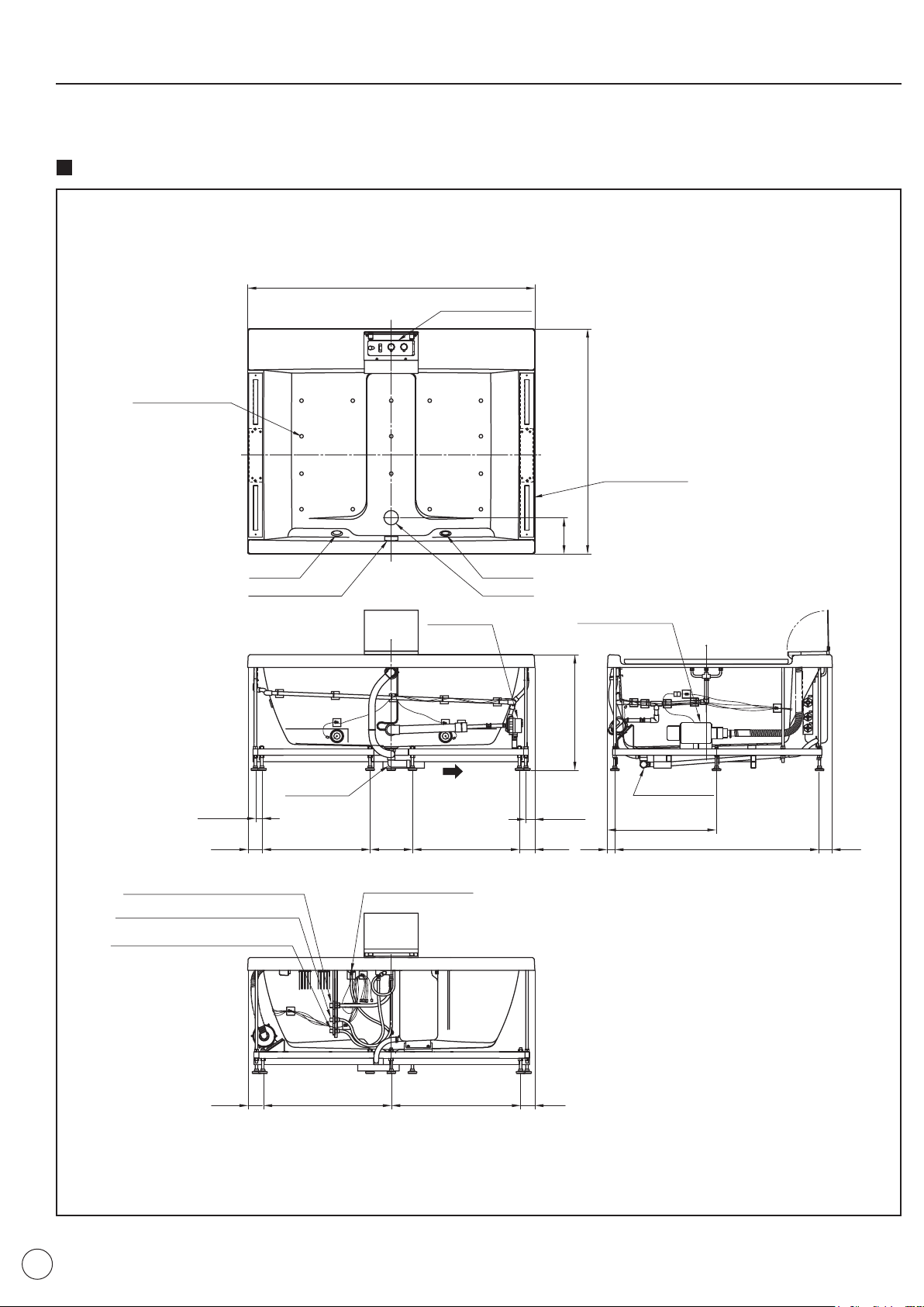
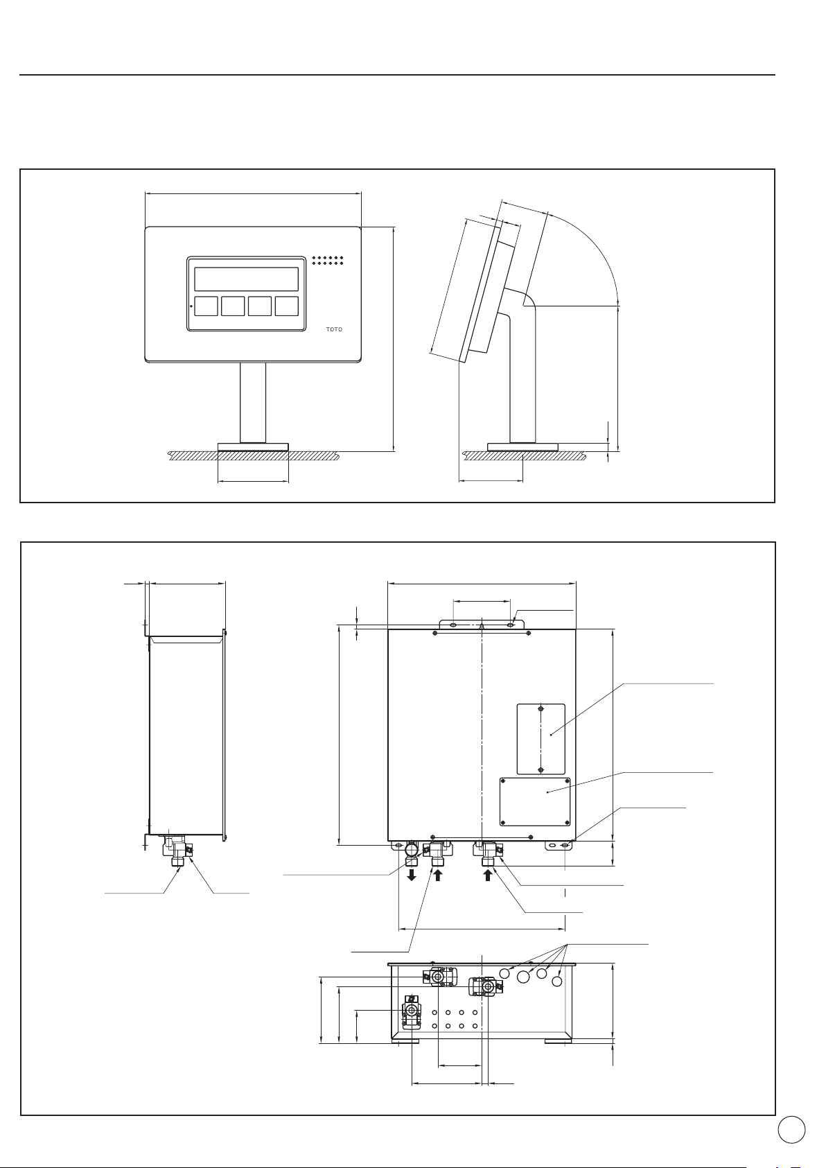
3. Dimension Drawings and Specifications
Air blower nozzle
(15 positions)
Headrest base
Air blower
5
2
7
1800
0
141
722
684
81128247
56
56
9667126667196
9680480496
Typ
Typ
Typ
Shower Box
Underwater lighting
Drain valve
Underwater lighting
Overflow
Shoulder
warmer pump
Drain elbow
Drainage
direction
Drain Fitting
for 1-1/2”
nominal pipe
Bath connection (TUB) (NPT 3/4)
Shower connection (H) (NPT 1/2)
Shower connection (C) (NPT 1/2)
Water Level Sensor
3-1 Bathtub, Controller stand and Function Module
Bathtub
10
Page 11
■■
73
5
52
246
7
1
2
85
1
φ80
9
°
5
7
4
5
5
6
1
HCTUB
Tub Connecting Port
Cold Water Supply Connecting Port
Drain Valve with Strainer
Hot Water Supply Connecting Port
Drain Valve with Strainer
Cord Access Port
Inspection Port (GFCI)
Inspection Port
(Line Connections)
6×14 Slots
6×14 Slots
373
49
4
94
1
721
4
7
99
158 14
0
710
1
674
6
5
128
42217010
9
Drain Valve
D
C
B
A
A - Supply circuit
B - Air blower
C - Controller stand
(remote)
D - Water sensor
Controller stand
■■
Function Module
11
Page 12
3-2 List of Specifications
External Dimensions 70 7/8" x 55 1/2" x 28 1/2" (1800 mm W, 1410 mm D, 725 mm H)
Weight 353 lbs. (160 kg)
Capacity 161 Gallons (610 L) to overflow line
Drain time 9 minutes 15 seconds
Material Acrylic Synthetic Marble
Number of drains 1
Tub filling flow rate Maximum 35 L/min.
Intake ports 1
Outlet ports 2
Lighting modules 2
Colors
Hot supply (shower) NPT 1/2
Cold supply (shower) NPT 1/2
Fill-tub (hot) NPT 3/4
Hot water supply 140 to 158°F (60 to 70°C)
Cold water supply 32 to 86°F (0 to 30°C) (No freezing)
Hot water supply NPT 3/4
Cold water supply NPT 3/4
Hater water NPT 3/4
AIRBATH™
Controller
Stand
Function
Module
Tub filling
Air blower Number of jets 15 on the bottom of the AIRBATH™
Shoulder
warmer
Underwater
lighting
Water pressure used (Clean-up shower) 0.08 to 0.75 MPa
Connecting
port diameter
Other Fill-tub fittings, 2-handle tube cleaning shower, headrest
Outside dimensions 9 5/8" x 4 1/2" x 10" (246 mm W, 113 mm D, 255 mm H)
Weight 6.2 lbs. (2.8 kg) (including the controller)
Rotation angle 90 °
Outside dimensions See dimensional diagrams
Weight 37.5 lbs. (17 kg)
Rated voltage 120 VAC
Rated frequency 60 Hz
Rated current 5.9 A
Rated power consumption 710 W
Installation location Indoor
Water pressure
water
temperature
Connecting
port diameter
3 types of patterns, 10 individual colors (controlled from the
function module)
29 to 108.75 psi (0.20 to 0.75 MPa) (The pressure differential of
the cold water is to be greater than that of the hot water and kept
within 0.lMPa.)
12
Page 13

4. Installation Procedure
6-1 Building a base for the bathtub ~ seating the bathtub (P. 18, P. 19)
(1) Building a base (P. 18)
(2) Plumbing and connecting the drain pipes (P. 18)
(3) Seating the bathtub (P. 19)
6-2 Finishing (P. 20, P. 21)
(1) Fixing the bathtub in place (P. 20)
(2) Plumbing and connecting the hot/cold pipes and the fill-tub pipe (P. 20)
(3) Connecting the cables (P. 20)
(4) Finishing the tiles (P. 21)
6-3 Controller stand installation (P. 22)
(1) Marking the pilot hole, drilling the hole and installing the plug (P. 22)
(2) Attach the base (P. 23)
(3) Install the slip ring (P. 24)
(4) Controller stand installation (P. 25)
6-4 Function module installation (P. 26 to P. 32)
(1) Advance preparation (P. 26)
(2) Function module installation (P. 26)
(3) Positioning of holes for installing the function module installation screws (P. 27)
(4) Function module installation (P. 28)
(5) Plumbing the equipment (P. 28)
(6) Inspecting for leaks in the fill-tub plumbing (P. 29)
(7) Plumbing the hot, cold and fill-tub pipes (P. 30)
(8) Electrical work (P. 31, P. 32)
6-5 Confirmation and trial operation (P. 33 to P. 39)
13
Page 14

5. Installation Precautions
(Doing so could cause damage.)
(Doing so could cause damage.)
(Doing so could cause damage.)
(Doing so could cause damage.)
(Doing so could discolor the tub.)
5-1 Bathtub
Bathtub
●●
Before installing the bathtub,
check the bathtub itself and the
1
plumbing for problems.
Do not place lit cigarettes on
the bathtub or direct the flame
4
of a blowtorch at it.
Do not place anything heavy on
the tub or anything in the tub for
2 3
standing on.
Do not install the tub with the
rim surface as its sole support.
5 6
Do not remove the protective
sheet on the tub. Also, the
bathtub should be protected
with cardboard or other material
until the bathroom construction
is finished.
Do not install the bathtub
outdoors or in a location where
the sun will hit it all day
(solarium or similar room).
When transporting the bathtub, do not carry by the hoses or plumbing or strike it with anything hard.
7
● When disposing of a NEOREST®AIRBATH™ , please ask a certified disposal professional to dispose of it.
14
Page 15

5-2 Function module
Power supply cord (6.6 ft (2 m))
Junction cable
(23 ft (7 m) or 49 ft (15 m))
• Signal junction cable
• Air blower junction cable
• Shoulder warmer junction cable
• Underwater illumination
junction cable
Fill-tub route
Cold water
supply route
Hot water supply route
Drain Valve
Water heater
Hot water supply
Cold water
NPT1/2
NPT3/4
NPT3/4
Drain Pipe
The function module requires a hot water supply temperature of at least 140°F (60°C). (No more than 158°F (70°C).
If the supply temperature of the hot water is too low, it won't be possible to fill the tub to the temperature setting on
the controller.
The function module mixes the supply of hot and cold water and runs hot water out of the fill-tub outlet, so the
temperature of the water flowing out will be lower than the temperature of the water being supplied to the function
module.
The pressure of the hot and cold water supplied to the function module must be at least 29 psi (0.20 MPa) (when
flowing). (No more than 108.75 psi (0.75 MPa)).
The pressure differential of the cold water is to be greater than that of the hot water and kept within
14.5 psi (0.10 MPa).
If the pressure is low, the water won't flow out like a waterfall. Additionally, it will take longer for the tub to fill with hot
water.
Supply Equipment Specifications
o Supply Pressure 29 to 108.75 psi (0.20 to 0.75 MPa)
o Supply Temperature 140 to 158°F (60 to 70°C)
o Hot water usage
• Max. temperature 113°F (45°C)
• Max. flow rate 9.2 gal/min. (35 L/min.)
• Max. capacity 145 gal. (550 L)
The diameter of the function module connector is NPT 3/4. Please do not make the diameter of the plumbing smaller
than the diameter of the connector to the function module.
The use of equipment below full capacity could lead to problems for the clients.
It is necessary to have space between the tip of the water pipe drainage. If not the water could backflow.
15
Page 16

5-3 Clean-up Shower Installation Conditions
● When attaching the Clean-up Shower, please observe the following conditions of use.
(1) Confirmation of water pressure
Supply hot/cold water pressure:
❈ If the supply water pressure exceeds 108.75 psi (0.75 MPa), please reduce the pressure to around 29 psi
(0.20 MPa) using a commercially available pressure-reducing valve.
Minimum required pressure: 11.6 psi (0.08 MPa)
{
Maximum water pressure: 108.75 psi (0.75 MPa)
(2) Confirmation of hot water supply temperature
● Please keep the hot water supply temperature no higher than 158°F (70°C).
Note also that for safety, we recommend a hot water supply temperature of 140°F (60°C).
● Please do not use steam in place of a hot water supply.
(3) Plumbing
● Please do not connect the hot and cold water backward.
Note also that in order to reduce resistance, the shortest distance possible should be used for the hot water supply
pipe from the hot water heater and insulation should be wrapped around the plumbing.
● Please implement countermeasures for freezing such as wrapping insulation around the pipes.
16
Page 17

5-4 Function module installation locations
Within 7m
Within 7m
Please locate the function module in a place where freezing and moisture from indoor water will not be a problem.
Please leave a space of at least 2 ft. (600 mm) in front of the equipment so that inspections or repairs can be made.
Also, please do not locate it on a second-story wall or other place without access.
Please locate the function module in a place that is strong enough to bear its weight and a margin (40 lbs (18 kg)).
Please take the following into consideration when deciding where to place the function module.
- The length of the cables to the equipment (pumps and the like) that will be installed with the bathtub
A 23 ft. (7 m) or 49 ft. (15 m) cable is provided.
- A height which allows the plumbing to be inclined so that the bathtub can be drained more easily when removing the
water.
Please install in a location that will not cause damage if there is water leakage.
If you install in a location that can cause damage please add water protection and appropriate drainage on the floor.
If the tub installation is downstairs the function module should be within 23 ft. (7 m) of the top of the tub (see diagram).
If the tub installation is upstairs the function module should be within 23 ft. (7 m) of the top of the tub (see diagram).
In this case the supplied water pressure should be 29 psi (0.20 MPa) above head pressure.
17
Page 18

6. Installation requirements
Inspection port
(within 15 inches)
Junction cable
Cold water
supply
Hot water
supply
Fill-tub pipe
1
00
or
m
ore
1
800
1
00
or
m
ore
5
00
or
m
ore
(In
spe
cti
on
por
t s
pace
)
0
1
4
1
1
0
0
Bathtub rim reference line
W
ithin
15 inches
W
ith
in
15
inc
hes
W
ith
in
15
inc
hes
(In
spe
cti
on
por
t s
pace
)
*B
athtub
ce
nte
r
m
odul
e
(In
spe
cti
on
por
t s
pace
)
*1
*1
(Inspection
po
rt space
)
1-1/2” Nominal Pipe
Arrange on site
Approximately
700 mm
Upper surface of rim
6-1 Building a base for the bathtub ~ seating the bathtub
(1) Building a base
Please allow at least 100 mm or more clearance beyond the external dimensions when determining the position of the
bathtub.
Please set up the hot/cold water supply pipes and the fill-tub pipe on the side with the inspection port.
Also, please set aside space for inspection ports at the rear of the bathtub center module or the function module
(pump) (one or the other of *1).
Please fit the hot/cold water pipes with anti-backwash valves and shut-off valves.
(2) Plumbing and connecting the drain pipes
For a directly connected drain
Please connect the plumbing to the drain fittings of the bathtub in advance.
18
All of the plumbing is to be arranged on site.
Please refer to the provided template (0GU5079).
Page 19

(3) Seating the bathtub
Connecting pipe
Cold water supply line (NPT 1/2)
Fill tub line (NPT 3/4)
Hot water supply line (NPT 1/2)
Level
Level
Adjuster leg
Lock nut
(Hexagonal)
● Please attach the plumbing that will connect the hot and cold water supplies and the fill-tub line to the bathtub.
● Please make the bathtub level.
● The feet of the bathtub are adjuster bolts, so please loosen the lock nut (hexagonal) and adjust it until it is level.
● After using a level to make fine adjustments to bathtub, please tighten the lock nuts on the adjuster legs.
19
Page 20

6-2 Finishing
Mortar Mortar
Tag
Connector
Controller Stand Connector
(see 6-3 Controller Stand Installation (4))
(1) Fixing the bathtub in place
● Please fix the bathtub in place using mortar or a powerful adhesive.
Caution: Please be careful not to get any mortar or adhesive on the bathtub itself.
(2) Plumbing and connecting the hot/cold pipes and the fill-tub pipe
● Please connect the connecting plumbing installed on the bathtub to the hot/cold water supply pipes and the fill-tub
pipe that were set up in advance.
(3) Connecting the cables
● Please connect the fill-tub unit and the connecting junction cables to the respective cables on the bathtub side.
❈ Check the tags on the junction cable and the bathtub-side cables when making the connections.
20
Page 21

(4) Finishing the tiles
Deck
Inspection port
(at least 15 x 15 inches)
Inspection port
(at least 15 x 15 inches)
Inspection port
(at least 15 x 15 inches)
Controller Stand Attachment Module
Tile insertion
Within
5 mm
Within
5 mm
Joint backing
material
Joint backing
material
Silicone
Silicone
Convoluted
Flexible
Tubing
Bathtub
within 3mm
Tile insertion
● Please build a deck around the perimeter with an apron and tiles.
❈ Before installing the deck, please fill the bathtub with water, test run it and check for leaks around the pipe
connections. Please refer to the POO concerning test runs.
❈ Before tiling the deck surface, determine the position of the remote control stand and insert a sheathing pipe for the
cable.
❈ Be sure to leave a gap in the space between the bathtub and the tiles and then fill in the gap between the bathtub
and the tiles using an alcohol-free type of silicone.
❈ Please arrange for a joint-backing material on site.
Also, when forming the deck apron, please be sure to affix the joint-backing material to the deck surface or the back
surface of the bathtub rim before putting the tub in place. It may not be possible to apply the joint-backing material
after the bathtub has been put in place.
21
Page 22

6-3 Controller stand installation
°54
°
54
Groove
Movable range of remote controller stand
❈ 45° to the left and right of the front
Front
Groove in base
Back of base
Drill
Pilot hole
Plug
Pilot hole
(1) Marking the pilot hole, drilling the hole and installing the plug
➀ Cut the conduit sheath for the wires that protrude from the surface of the deck.
➁ Place the base so that the conduit sheath stays in the center and, being careful of the installation direction, mark the
three places where the holes will be that will secure the base
❈ Please be careful of the position of the groove and the front during installation and fix it in place, keeping the
movable range of the remote controller in mind.
➂ Drill the pilot holes the size of the plug where the marks were made.
(Please choose plugs that fit the 4 x 30 Philips head tapping screws.)
➃ Check that the position of the hole is not in a hollow part of the tile
surface. If it is hollow, please fix it in place using an adhesive tapping
anchor.
➄ Place the plug in the pilot hole and pound it in.
➅ To keep water from seeping through, seal the gap between the plug and
the hole.
22
Page 23

(2) Attach the base
Deck
installation screws
Base
Power
Screwdriver
Protective sheet
Base
Base cover
➀ Use the screws that came with the base to attach it so that it faces the right direction.
Do not remove the protective sheet on the base.
• Doing so could cause problems or make the unit malfunction, due to debris or damage to the O ring.
Prohibited
• This will make it more difficult to install the slip ring and could bend or damage the slip ring.
➁ Attach the base cover.
23
Page 24

(3) Install the slip ring
Slit
Front surface
Slip ring holder
Back surface
Slit
Slip ring
Slip ring
Protective sheet
Place the slip ring on the base, being careful not to confuse the front and back surfaces of slip ring holder.
Be sure to attach the slip ring.
• Not installing it could bring the base cover and stand into contact and damage the base cover.
Always do this
Install the slip ring very carefully.
• If the slip ring becomes "stretched" or "misshapen", it may not perform its intended function.
Always do this
Remove the slip ring holder from the base while leaving the slip ring in place by tearing off the part of the slip ring
holder with the slit in it to the right and left.
Remove the protective sheet on the base.
Please remove the protective sheet carefully. Otherwise, the slip ring could become damaged or misshapen.
24
Page 25

(4) Controller stand installation
Controller
stand
Connector
Front
Allen head set screw
Front
Front
➀ After connecting the splitter cord that comes with the unit to the signal relay cable (6-2 Finishing (3)), remove it from
the base through the conduit sheath and connect it to the controller stand itself.
➁ Press the controller stand into the base.
➁ Tighten the included Allen head set screw in the hole in the back of the controller stand. After turning the screw until it
stops, turn it 180 to 360° backward from where it stopped turning.
❈ Please be careful not to let the screw protrude when doing so.
Always turn back the screw.
• Neglecting to do so could keep the remote controller stand from moving back and forth.
Always do this
25
Page 26

6-4 Function module installation
Bathtub
Bathtub
Water
Hot
water
Drain
Water removal valve
Anti-backwash valve
Anti-backwash valve
Shut-off valve
Shut-off valve
Function Module
(1) Advance preparation
➀ Install shut-off valves and anti-backwash valves on the hot and cold water supply pipes.
➁ Run the pipes and cables for the connection between the bathtub and the function module.
❈ Install a water removal valve on the fill-tub pipes and make arrangements for a suitable water drainage process.
(2) Function module installation
● The weight of the equipment will hang on the installation wall, so it should be reinforced if it isn't strong enough.
The supporting structure should be capable of supporting at least 40 lbs (18 kg).
● When installing the equipment, do not drop it or hit it against anything.
Doing so could break or damage the parts inside the equipment.
● Be sure to install it on a vertical wall.
● The plumbing that is connected to the equipment should be installed so that there will be no safety problems with
respect to earthquakes, other vibration or physical impact and caulking material should be used to seal the points
where the hot and cold water and the power lines pass through the walls.
26
Page 27

(3) Positioning of holes for function module installation screws
Installation
plate
Function module
Tapping anchor
Tapping screw
Pilot hole
Position
hole
Function module
➀ Drill pilot holes for positioning the function module, pound in the curl plug (arranged on site) and use a tapping screw
for positioning. Then, hang the installation plate of the function module (above) on the tapping screw.
➁ Position the holes for the screws (two above and two below) and remove the function module briefly.
27
Page 28

(4) Function module installation
➀ Drill the pilot hole in the position determined for the screw and pound in the tapping anchor (arranged on site).
➁ Replace the function module on the tapping screws and fix the tapping screws (two above and two below) into place.
➂ Waterproof the area so that water cannot get into the building from the screws that secure the equipment.
(5) Plumbing the equipment
■■
Precautions when plumbing
• If the plumbing materials are specified by the relevant local and national plumbing authorities, comply with those
specifications.
• Be sure to flush filings, sand and debris from inside the pipes using water before connecting the function module.
• Use a union junction or similar means on the connection port and do not use excessive force.
• The diameter of the pipe is not to be less than the diameter of the function module connector (3/4).
• When the water pressure is high, either install a pressure-reducing valve or a device to prevent "water hammers."
(Recommended water pressure: 29 to 108.75 psi (0.20 to 0.75 MPa)).
• Keep the number of unions as small as possible and do not use complicated plumbing. Additionally, do not plumb in
such a way that air can become trapped in the pipes.
● Hot and cold water supply plumbing.
• Install an anti-backwash valve, a shut-off valve or a shut-off valve with an anti-backwash valve near the hot and cold
water supply ports.
• In order for the customer to have a pleasant experience using this equipment, a hot and cold water supply pressure of
29 to 108.75 psi (0.20 to 0.75 MPa) is required. If the water pressure is low, the equipment will not function properly
and could lead to trouble with the customer, so be prepared to install a booster pump as a countermeasure.
● Fill-tub plumbing.
• The pipes that are used with the fill-tub feature are to have a maximum length of 49.2 ft (15 m) and 10 changes of
direction.
• Please incline the pipes so that it will be easier to remove water from the pipes when draining water from the pipes.
• Please allow sufficient space for the end of the water-removal pipe and the drain opening.
If there is no space, backed up water could flow back inside.
28
Page 29

(6) Inspecting for leaks in the fill-tub plumbing
Booster pump
Gauge
Caution
• Do not apply additional pressure to the equipment.
Inspection pressure and time: 43.5 psi (0.30 MPa) for five minutes or longer.
➀ Install a valve on one end of the fill-tub plumbing. (Valve open.)
➁ Install a booster pump on the other end to feed water into the fill-tub plumbing.
➂ Once the air has been removed from the fill-tub plumbing and it has been filled with water, close the installed valve.
➃ Inspect for leaks.
Inspection pressure and time: 43.5 psi (0.30 MPa) for five minutes or longer.
• Use a pressure meter that suits the pressure being checked when inspecting the pressure.
• Be sure that there are no leaks or pressure drops across the gauge.
❈ Do not apply pressure to the equipment itself.
❈ If pressure leaks are discovered, run the test again after fixing the leaky areas.
29
Page 30

(7) Plumbing the hot, cold and fill-tub pipes
Insulate so that
there is no gap.
Wrap the insulation so that the waterremoval valve can be operated.
Insulate so that there
is no gap.
Anti-backwash valve
Shut-off valve
To bathtub
Water
Drain
Hot water (Water heater)
To drain line
Power supply cord
➀ Connect the pipes described so far to their respective connection ports on the function module.
➁ Open the shut-off valves on the hot and cold water supply lines and check to see that there are no leaks from the
joints.
➂ After connecting the cables and the bathtub equipment (Page 31), fill the tub and confirm that there is no water
leaking from the joints in the fill-tub pipes (two places: on the function module side and the bathtub side).
● Freezing prevention (Please implement this in locations where there is a risk of the equipment or pipes freezing.)
• To prevent freezing, insulation (insulating material, electric heaters, etc.) should be used that is appropriate to the
• Insulate the plumbing completely after checking to see that there are no leaks from the hot, cold or fill-tube water
• In order to be able to drain water from inside the pipes, do not wrap the water removal valve with insulation.
region.
lines.
30
Page 31

(8) Electrical work
Connector cover
Power supply terminal strip
Power supply cord
Grounding screw
Terminal strip
Air blower cord
● Power supply check.
Connect Ground
• All electrical connections must be in accordance with local codes, ordinances, and
the National Electrical Code (NEC).
If you are unfamiliar with methods of installing electrical wiring and appliances, you
should secure the services of a qualified licensed electrician.
Warning
Improperly performed work could result in breakdowns or current leaks that could
lead to electric shocks.
Install to permit access for servicing.
An equipment grounding terminal is provided in the field wiring compartment. To
reduce the risk of electric shock, this Terminal must be connected to the grounding
means provided In the electric supply panel with a conductor equivalent in size to
the circuit conductor supplying this equipment.
Install this unit in accordance with the National Electrical Code (NEC) NFPA 70 and
Canadian Electrical Code, Part 1.
Connect only to a branch circuit protected by an overcurrent protective device rated
not more than 15A.
The power supply for this function module is 120 V (60 Hz) and the power consumption is 710 W.
● Connecting the cable and the bathtub equipment
➀ Remove the cover on the connector
➁ Using a conduit joint (arranged on site), pull the power supply cord (arranged on site) through the hole in the bottom
and push it into the power supply terminal strip. During this operation, please be careful of the size of the wire and
the length of insulation that is stripped away.
❈ Proper size: AWG12 or 14
Stripped length: 0.55 in (14 mm)
Pull the grounding wire (arranged on site) through
the same hole and fix it to the ground with a screw.
➂ Using a conduit joint (arranged on site), pull the air-
blower cord (arranged on site) through the hole in
the bottom and fix it to the power supply terminal
strip with a screw.
When doing this, please make sure that the color of
the wire and the color of the terminal strip label
match.
31
Page 32

➃ Set up the clamp connector (3/4) that comes with the "Control Unit" of the power supply relay cable.
Clamp
connector (3/4)
Power supply relay cable
Clamp
connector (1/2)
Signal relay cable
Cover
Set up the clamp connector (1/2) that comes with the "Control Unit" of the signal relay cable.
Pull the cables ➄ and ➃ through their respective holes in the bottom and fix the clamp connectors in place.
➅ Attach the cover after connecting each of the connectors and you are finished.
32
Page 33

6-5 Confirmation and trial operation
1
Remove the operation
cover from the
Supplementary
protector.
Supplementary protector
operation cover
ON
OFF
3
Push the test button on
the Supplementary
protector.
Power supply
lever
Test button
ON
OFF
Power supply
lever
❈ If the power supply lever changes
from ON to OFF< then it is
functioning normally.
Set the power supply lever
on the Supplementary
protector to ON
2
Run trial operations as described in the Instruction Manual and, after confirming that the product runs normally, tell the
customer how to use it and deliver it to the customer.
■ Inspection
• After the unit is installed, please be sure to check the operation of the
Warning
Always do this.
Supplementary protector. An improperly functioning Supplementary
protector could lead to electric shock or fire
33
Page 34

■ Trial operation preparation
Cold water shut-off valve
Hot water
shut-off valve
Hot water heater
(Not included with the product)
Function module
Cold
waterwater
Hot water
Power supply cord
(when flowing)
1
Confirm that electric power is
being supplied.
This should be performed after
confirming that the bathtub is empty.
2
Supply temperature: 140 to 158°F (60 to 70°C)
Supply pressure: 29 to 108.75 psi (0.20 to 0.75 MPa)
Supply water
pressure: 29 to 108.75 psi
(0.20 to 0.75 MPa)
(when flowing)
Open the hot and cold water shut-off valves connected
to the function module.
❈The position of the water shut-off valve will vary from place to place.
Please supply hot and cold water to the function module by opening the shut-off valves.
Hot water
■ Trial operation
Please run the unit in order of operations (1) to (6).
❈ Do not apply pressure to the equipment itself.
(1) Bathtub data reset
➀ Open the bathtub drain valve and empty the bathtub.
➁ Set the On/Off button on the controller to OFF.
➂ Turn the to ON.
Please open the drain valve of the bathtub so that no water remains in the bathtub.
The draining operations will end automatically after approximately 2 minutes.
34
Page 35

(2) Fill-tub operation
➀ Close the drain valve in the bathtub and set the On/Off button on the controller to ON.
➁ Set to ON.
➂ Confirm that the fill-tub cascade is flowing out of the fill-tub outlet.
➃ Confirm that there are no leaks in the plumbing.
➄ Wait until the fill-tub feature finishes normally.
When the tub has been filled, a melody will play and then stop automatically.
(3) Air blower
❈ Please make sure that there is hot water in the tub after running the fill-tub feature.
➀ Set the On/Off button on the controller to ON.
➁ Set to ON.
➂ Confirm that there is air flowing out of the nozzles in the bottom of the bathtub.
➃ Confirm that there are no air or water leaks in the plumbing.
➄ Set to OFF.
(4) Shoulder warmer
❈ Please make sure that there is hot water in the tub after running the fill-tub feature.
➀ Set the On/Off button on the controller to ON.
➁ Set to ON.
➂ Confirm that there is water flowing out of the (two) shoulder warmer outlets.
➃ Confirm that there are no leaks in the plumbing.
➄ Set to OFF.
(5) Underwater illumination
➀ Set the On/Off button on the controller to ON.
➁ Set to ON.
➂ Confirm that the (two) lighting modules are turned on.
➃ Confirm that there are no leaks in the lighting modules.
➄ Set to OFF.
35
Page 36

(6) Purge operation
➀ Remove the drain plug in the bathtub and empty the bathtub.
➁ Set the On/Off button on the controller to OFF.
➂ Set to ON.
Please remove the drain plug in the bathtub so that the water in the bathtub will all run out.
The purge operation will end automatically after approximately two minutes.
■ Handling problems
If there are problems with operation, please refer to the section on troubleshooting in the Instruction Manual.
When an error code is displayed
Error Code Cause Response
032 Drain valve open ❈ Is the bathtub drain valve closed?
079 No hot water
152
262 Water level sensor open circuit
572 No water ❈ Is the water main/shut-off valve turned on?
C04
Other --- Please try again after resetting the error.
Incoming water temperature
problem
Shoulder warming pump rpm
problem
❈ Is sufficient hot water available from the water heater?
• Please check the temperature setting/operation of the water heater.
❈ Is hot water being supplied to the cold water connection port of
the function module?
• Please check the connections of the plumbing to the function
module.
❈ Is the water sensor cable connected?
❈ Is there a break in the water sensor cable?
❈ Is there enough hot water in the bathtub?
❈ Is debris blocking the intake port?
❈ Is the intake port blocked?
36
Page 37

Error reset method
Errors can be reset with the button that displays the error codes.
If the error codes aren't displayed
The lights on the controller don't work
• Is the controller cable connected?
• Is the controller cable broken?
• Is the power supply reaching the function module?
Air blower doesn't function
• Is the air pump cable connected?
• Is the air pump cable broken?
The underwater lighting doesn't turn on
• Is the underwater lighting cable connected?
• Is the underwater lighting cable broken?
❈Please refer to the Instruction Manual concerning other problems.
37
Page 38

■ Cleaning the strainer in the water drain lug
Hot water
connection
Hot water valveCold water valve
Cold water
connection
Close Close
Debris in the plumbing will collect in the strainer, so after connecting the plumbing and running water through it and after
the trial operations, please be sure to clean the strainer.
Caution
If the product won't be delivered to the customer for a long time or if it will not be used for a
long time, please remove the water from the function module and shut off the power. (See
Instruction Manual.)
❈ After the water has run out of the fill-tub outlet, the water inside the function module will still be quite hot. Please wait
until the equipment cools to avoid scalds or burns.
❈ Hot and cold water will run out of the water drain lug, so please place a bucket or other container underneath the
function module to catch the water.
➀ Close the hot/cold water valves in the plumbing connected to the connection ports.
❈ The location of the shut-off valves will vary with the installation site.
➁ Set the on the controller to ON and wait around 20 seconds.
❈ Please do this with the On/Off button set to ON.
➂ After confirming that no water is flowing out of the fill-tub outlet, turn the On/Off button to OFF.
• If the water continues flowing, please set the On/Off button to OFF again and start from step (1).
Sometimes, the controller will display error code 572.
• This is a notice that the water has been shut off. After resetting the error (See Page 37), set the On/Off
button to OFF and proceed to step (4).
38
Page 39

➃ Remove the water drain lugs in the hot and cold water connection ports.
Water drain lug
(with strainer)
Hot water
connector
Cold water
connector
Water drain lug
(with strainer)
Water drain lug
Packing
Toothbrush
Strainer
Packing
OpenOpen
Hot water
connector
Cold water
connector
Hot water valveCold water valve
❈ Hot water will come out of the function module when removing the water drain lugs, so please be careful.
❈ When the water drain lugs cannot be removed by turning them by hand, please put the end of a screwdriver or
other tool in the hole in the water drain lug and use that to turn them.
➄ Rinse the strainer with water while brushing it with a toothbrush.
❈ Please keep debris from scratching or getting on the packing. Otherwise, leaks could develop or debris could get
inside the function module, causing problems.
➅ Reattach the water drain lugs to the hot and cold water connectors as they were initially.
➆ Open the hot and cold water valves and check to see that there is no water leaking around the drain lugs.
39
Page 40

Recycled
TOTO USA INC. 1155 Southern Road, Morrow, GA 30260
Tel : (888) 295-8134
• Fax : (800)699-4889
www.totousa.com
Printed in USA © TOTO USA Inc.
0GU5076
11-9-07
 Loading...