

Page 1
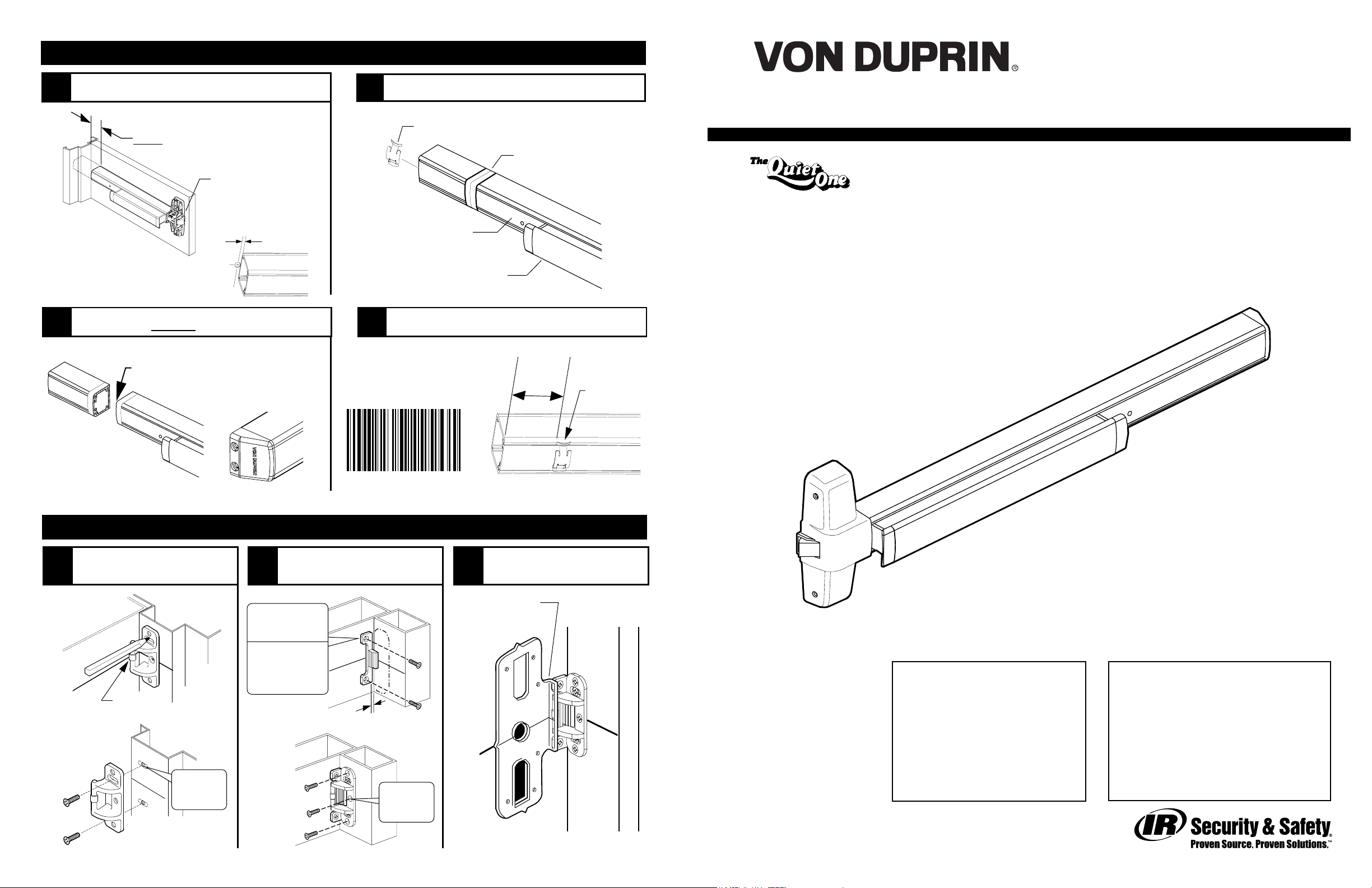
CUT DEVICE
1
3
Measure amount to cut off device.
1-1/2” minimum clearance
(with endcap removed)
Note
If 5/8” diameter wire access hole
has been predrilled in door, cut
device 5/16” from center of hole.
Cut device square.
Cut device square
and remove all
burrs
Device aligned
with mounting
holes
5/16”
NOTE: Device must
be cut square for
proper end cap fit
2
9
4
Tape and mark area being cut.
Remove anti-rattle clip
Tape
Cover plate
(flush to pushbar)
Pushbar
Slide anti-rattle clip into device.
2”
Minimum
Installation Instructions
®
98/99 Series Rim Exit Device
Devices covered by these instructions:
98/99 Rim Exit Device
98/99-F (Fire) Rim Exit Device
CD98/CD99 (Cylinder Dogging) Rim Exit Device
98-2/99-2 (Double Cylinder) Rim Exit Device
EL98/EL99 (Electric Latch Retraction) Rim Exit Device
Anti-rattle
clip
911373-00
499F STRIKE INSTALLATION
Prepare and install screws
1
through 2 strike slots.
C
L
Roller
(against door)
C
L
2
3
#25 Drill
#10-24 tap
2 places
If using a mullion, holes
may be predrilled
8
Install strike hook and
additional strike screws.
#25 Drill
#10-24 tap
MetalWood
2 places
13/32” Drill
thru for
sex bolts
2 places
Strike
hook
1/16”
4
#25 Drill
#10-24 tap
3 places
Template aligns as shown.
3
Template
(align on C and
against strike)
C
L
L
Please give these instructions to building owner after device is installed
Special tools needed:
5/64” hex wrench
#10-24 tap
This product is covered by the
following patent numbers:
3,767,238 4,427,223
3,854,763 4,466,643
4,167,280 4,741,563
911373_00(4) Copyright © 2005 Ingersoll-Rand. All rights reserved.
5/8” spade drill (
Drill bits: #25, 1/8”, 1/4”,
5/16”, 3/8”, 13/32”
99-F wood door)
Index:
• Screw chart ................................... 2
• Preparation chart ......................... 3
• Device installation ...................4-5
• Optional equipment ................6-7
• Cut device ..................................... 8
• 499F strike installation ............... 8
Page 2
SCREW CHART
OPTIONAL EQUIPMENT - CONTINUED
A
B
#10-24 X 3/4”
- Packaged with trim -
#10 X 1-1/2” Wood screw
#10-24 X 1”
#10-24 X 1-1/2”
#10 X 1-1/4” Wood screw
#10-24 X 1-3/8”
#10-24 X 1-7/8”
Metal frame
Wood frame
Surface mount or
Sex bolts (1-3/4” door)
Sex bolts (2-1/4” door)
Surface mount (wood)
990 Trims (1-3/4” door)
990 Trims (2-1/4” door)
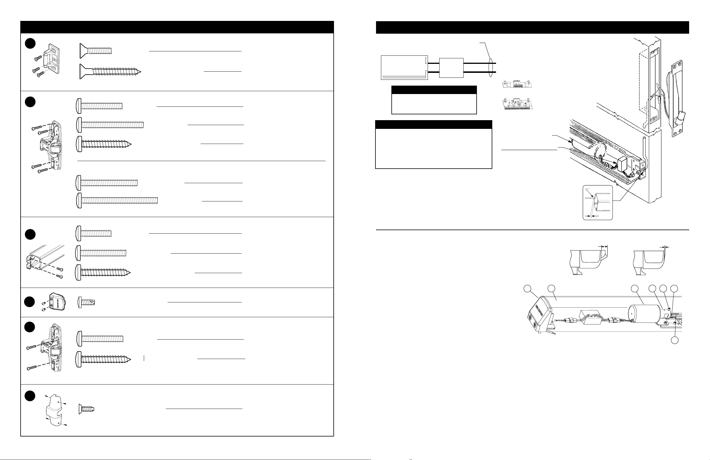
12 AWG required for distances up to 200’
14 AWG permitted for distances 0-100’
EL
Solenoid
ELECTRICAL SPECIFICATIONS
Voltage: 24 VDC
Current: 16 A inrush (0.3 sec.)
0.25 A holding
When power is applied to the potted circuit
board, the solenoid receives a momentary
signal to retract and a separate signal to hold
as long as power is applied. When attempting
to retract solenoid again, power must be
removed from the circuit and reapplied.
Potted
circuit
board
NOTE
Black
Black
EL WIRING
Solenoid draws 16 A inrush current from PS873.
Solenoid must be wired to a PS873 logic board:
}
If 871-2 logic board, refer
to Von Duprin instructions
941352.
If other 873 logic board,
refer to Von Duprin
instructions 941356.
Solenoid
Potted Circuit Board
Install after device has
been mounted on door
Do not cut device with potted
circuit board installed
Troubleshooting solenoid operation
If the solenoid fails to retract the latch bolt when power is applied, recheck wiring for
proper connections.
If solenoid retracts latch bolt momentarily but will not remain in energized position:
1. Check wiring for proper connections, guage, and distances.
2. Check for latch bolt binding caused by improper strike installation, warped door, etc.
5/8” dia.
C
L
5/16”
Electric
power
transfer
Drill 5/8”dia. wire access hole
thru device side of door.
C
D
#10-24 X 3/4”
#10-24 X 1-1/8”
#10 X 1-1/4” Wood screw
#10-16 X 3/8” Thread cutting
E
#10-24 X 1”
#10 X 1-1/4” Wood screw
F
#8-18 X 3/8” Thread cutting
2
2
Surface mount or
Sex bolts (1-3/4” door)
Sex bolts (2-1/4” door)
Surface mount (wood)
End cap screw
Surface mount (metal)
Surface mount (wood)
Cover screw
EL ADJUSTMENT PROCEDURE
A. Check for proper function:
1. Make sure device is not dogged.
2. Depress pushbar and make sure latch bolts
retracts and extends fully (see Figure 3).
3. Electrically energize solenoid and hold.
4. Check latch bolt(s) for full retraction (must
clear strike (see Figure 3).
5. Release solenoid and check latch bolt
extension (see Figure 3).
6. Continue to Section B if device does not
function electrically.
B. Determine if dogging rod adjustment is too long or short:
1. The dogging rod adjustment is too long if latch bolt
does not retract and clear strike (see Section C for
adjustment).
2. The dogging rod adjustment is too short if latch bolt
does not fully extend or latch bolt fully retracts but
solenoid releases while energized (see Section D for
adjustment).
C. Adjust solenoid if dogging rod is too long (see Figure 4):
1. Remove end cap c and dogging cover d.
2. Loosen cap screw e.
3. Hold plunger g depressed in solenoid housing h.
Note: Push hard against plunger g to overcome
an internal spring in solenoid housing h.
4. Turned threaded bushing f in to shorten dogging
rod i so latch bolt fully retracts.
5. Tighten cap screw e.
Note: Cap screw e must be tightened against
flat on threaded bushing f. Apply a few
drops of Loc-Tite 222 to threads of cap
screw e.
6. Replace dogging cover d and end cap c.
7. Return to Section A to check for proper function.
Latch bolt extended
3/4”
Latch bolt retracted
Flush within 1/16”
Figure 3
1
2
6
Figure 4
D. Solenoid adjustment if dogging rod adjustment
is too short (see Figure 4):
1. Remove end cap c and dogging cover d.
2.
Loosen cap screw e.
3. Hold plunger g depressed in solenoid housing h.
4. Turn threaded bushing f out to lengthen
dogging rod i so plunger g just bottoms in
solenoid housing h and latch bolt is fully retracted.
Note: Push hard against plunger g to overcome
5. Tighten cap screw e.
6. Replace dogging cover d and end cap c.
7. Return to Section A to check for proper function.
an internal spring in solenoid housing h.
Note: Cap screw e must be tightened against flat
on threaded bushing f. Apply a few drops of
Loc-Tite 222 to threads of cap screw e.
35
4
7
7
Page 3

OPTIONAL EQUIPMENT
CD (CYLINDER DOGGING)
1. Remove mortise cylinder cam and
reinstall in reverse (Figure 1).
2. Insert key and rotate cam to install
the cylinder to the cover plate (Figure 2).
3. Remove key to slide cover plate in
position in the mechanism case.
Std. mortise
Std. mortise
cylinder
cylinder
Offset toward
pushbar
Dogging
plate cover
Std. mortise
cylinder
Cylinder
collar
PREPARATION CHART
Go to instructions on next page before using preparation chart
*End cap bracket - 2 holes
Surface mount Sex bolts
#25 Drill
Metal
#10-24 tap
1/8” Drill
pilot 1” deep
Wood
*Prepare holes after lock side of device
is mounted and hinge side is leveled
1/4” Drill (device side)
Metal
13/32” Drill (trim side)
13/32”
Wood
Drill thru
C
X
Center case - 4 holes
Surface mount Sex bolts or 990 trims
#25 Drill
Metal
#10-24 tap
1/8” Drill
pilot 1” deep
Wood
L
Center case - 2 support holes
1/4” Drill (device side)
Metal
13/32” Drill (trim side)
13/32”
Wood
Drill thru
Mortise
cylinder
cam
CD function conversion
Mortise
cylinder
cam
Figure 1
Dogging procedure
Turn cylinder key clockwise approx. 1/8
turn for standard dogging
Depress pushbar
99-2 (DOUBLE CYLINDER)
1. Remove center case cover.
2. Mount rim cylinder to cylinder bracket
as shown.
Cylinder
locating washer
Figure 2
#8-32 x 5/16”
PPHMS
Cylinder
lock nut
Mechanism
case
C
L
RHR shown
(LHR opposite)
Door cut-outs
Outside cylinder applications:
Mark with template and cut-out:
Metal door (cut device side)
Wood door (cut thru)
For trim applications with working
lever, thumbpiece, or knob:
Mark with template and cut out:
(cut device side only)
Metal
Wood
X
Wood or
#25 Drill #10-24 tap
1/8” Drill pilot 1” deep
For 98-F/99-F (fire) wood door
#825 Sex bolts (2) required
3/8” Drill thru
5/8” Spade drill
composite
1/16” Deep outside
CUT-OUT FOR 99-2 “DOUBLE CYLINDER” OPTION
1/16”
3. Mount cylinder and bracket
assembly to center case with two
#8-32 screws as shown.
11/16”
Cylinder Bracket
C
1-3/4”
1-3/8”
L
3
#8-32 X 5/16”
PPHMS
Cylinder Spacer
1-1/4”
Rim Cylinder
Assembly
Cylinder Mounting Screws
(do not over-tighten)
Device and strike
C
L
6
Page 4

1
Draw horizontal device and
strike center line (C ).
L
2
Align strike on C and mark
L
the two slotted holes.
3
Prepare 2 holes and install
a screw thru each slot.
4
Position template against strike
and on C and mark door.
L
5
Prepare lock side of door
for device and trim.
C
L
*39-13/16”
To finished
floor
RHR Shown
(LHR opposite)
For double doors with a
*
mullion and strike already
installed, use existing
strike center line.
C
299/299F Strike
L
Roller
(against door)
For 499F strike, see back
cover of this instruction.
C
See “Preparation Chart” on page 3 for
drill, tap, and cut-out information
See trim instructions for pull side door
preparation. Line X-X in trim instructions
is same as vertical device C .
X
L
#25 Drill
#10-24 tap
MetalWood
1/8” Drill
pilot 1” deep
299/299F Strike
Template
(align on C and
against strike)
L
L
C
L
X
A
See “Screw Chart” on page
2 for screw types and sizes
Mark
vertical C
Mark 6
holes
L
If using an outside cylinder, check NL
6
NL drive screw
Note: When the NL
drive screw is left in
back of device, the
outside cylinder
will function only
as a Night Latch.
drive screw and install tailpiece guide.
Rotate tailpiece
guide to match
tailpiece
4
5
When installing trim that has a
functional lever, knob, or thumb piece
AND an outside cylinder to lock and
unlock the trim, remove NL drive screw
from back of device.
DO NOT remove NL drive screw for
the following application:
NL, EO, DT, TP-2, L-2, and K-2 trims or
with 98/99-2 (double cylinder).
With “BE” trim, device may need
rehanded. Look for instructions on
back of trim.
Tailpiece guide
Tailpiece
1/2”
Cut tailpiece
if needed
Door
surface
7
9
Install trim (if using) and secure
device center case to door.
1-1/2” Minimum clearance
(with end cap removed)
if device is too long for
door, see “Cut Device”
on back cover
center
case
Trim
(optional)
B
Install mounting bracket
8
Mark and prepare 2
See “Preparation Chart” on
D
and end cap.
Mounting
bracket flush
Level device
mounting holes
page 3 for preparation
Secure
mounting bracket
and end cap
Install 2 support screws,
9
Center
case
cover
C
and center case cover.
Remove protective
film from pushbar
E
F
Support
screws (2)
For 98F/99F (fire rated) devices on
wood or composite door:
#825 sex bolts
required for 2
support screws
10
Adjust and secure strike.
299/299F Strike
3/16”
Shim for 3/16”
if shimming is
necessary
Strike plate
(299 only)
#25 Drill
#10-24 tap
MetalWood
1/8” Drill
pilot 1” deep
5
 Loading...