

Page 1

LCN
®
740100-00
Middle Swing Control Box
2900 Series, 9700 Series
Senior Swing Control Box
2800 Series, 9500 Series
LC N
121 West Railroad Avenue
Princeton, IL 61356-0100
1-800-526-2400
FAX: 800-248-1460
www.lcn.ingersollrand.com
®
Installation Instructions
© 2006 Ingersoll-Rand Company Limited
740100-00(5)
Page 2

!
These instructions are presented in step-by-step sequence. It is very important that
installation begins with “1. Pre-Installation Site and Product Check” (page 3) and
continues as directed after each section.
IMPORTANT
!
Always disconnect main power to the operator prior to replacing.
Control box contains no serviceable parts inside.
WARNINGS
CONTENTS
General Information ..................................................................................................................................... 2
Electrical Specifications ...................................................................................................... ........................ 3
Pre-Installation Site and Product Check ...................................................................................................... 3
Installation................................................................................................................................................... 4
Wiring ......................................................................................................................................................... 4
Keypad Settings ......................................................................................................................................... 8
System Test...............................................................................................................................................12
Troubleshooting..........................................................................................................................................13
Release for Service ....................................................................................................................................14
GENERAL INFORMATION
The Middle and Senior Swing Control Boxes are for use with the Middle and Senior Swing Power Operator
Systems, respectively . The systems can operate a single door (2810, 9530, 9540, 2910, 9730, and 9740
Series), a simultaneous pair of doors (2850, 9550, 2950, and 9750 Series), or an independent pair of doors
(2860, 9560, 2960, and 9760 Series).
ANSI/BHMA A156.19 Compliance
The Middle and Senior Swing Power Operator Systems are low energy products and must conform to the latest
version of ANSI/BHMA A156.19 (American National Standard for Power Assist and Low Energy Power Operated
Doors).
Installation Instructions
All installation instructions are valuable references and should be given to the building owner or maintenance
supervisor after installation is complete.
The Middle and Senior Swing Control Box installation instructions and the manufacturer’s instruction manual
accompanying any sensor must be referenced to ensure proper installation, setup, and operation.
Page 2 of 14 740100-00(5)
Page 3
ELECTRICAL SPECIFICATIONS
AC input voltage .....................................................120 V AC
AC fuse..................................................................120 VAC, 2.5 A time-delay fuse
Motor protection .....................................................Solid state failure detection and shutdown
Activate inputs .......................................................dry NO contacts (close contacts to open door)
Safety inputs..........................................................dry NO contacts (closed contacts indicate an obstruction)
Breakaway input ....................................................dry NC contacts (open contacts indicate breakaway)
3-position switch input............................................dry 3-position switch
Power Boost disable input......................................dry NO contacts (close contacts to disable Power Boost
Lock output ............................................................Form C dry relay contacts rated 8 A, 30 VDC maximum
Accessory power output.........................................24 V AC, 1.5 A (protected by resettable thermal fuse)
Logic power output .................................................5 V , 50 mA (protected by resett able thermal fuse)
1. PRE-INSTALLATION SITE AND PRODUCT CHECK
!
IMPORTANT
Factory Authorized Door Leaf Size and Weight
T y pe Width per Leaf Maximum Weight per Leaf
Single Door 36” to 48” 200 lb.
Simultaneous Pair 30” to 48” 200 lb.
1.1. All required installation steps listed before “8. Control Box Installation” in the Astro/Middle/Senior
Swing installation instructions (part No. 740132-00) should be completed before installing the
Middle/Senior Swing control box.
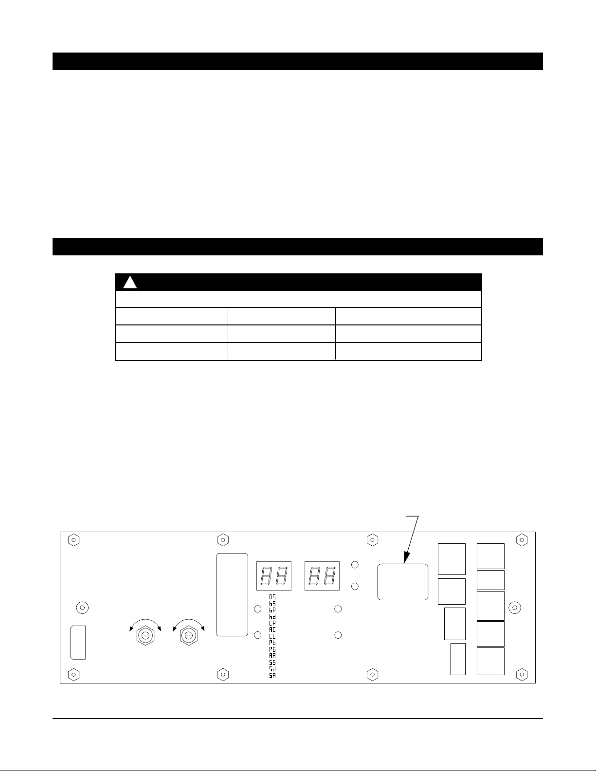
1.2. Check that the control box model (indicated on control box label; Figure 1-1) is correct for the application.
1.3. Check that the available AC voltage matches the control box voltage requirement (120 V AC).
1.4. Check that all accessories required for the application are on hand.
Label indicates model
COMPANION
MOTOR
CAUTION: 120 VAC
2.5 A TIME-DELAY FUSE
WARNING: FOR CONTINUED
PROTECTION AGAINST FIRE,
REPLACE ONLY WITH SAME
TYPE AND RA TING OF FUSE.
COMPANION MASTER
S
L
O
W
CLOSE
SPEED
F
S
A
L
S
O
T
W
CLOSE
SPEED
No Serviceable
F
A
S
T
SETTING
UP
Parts Inside
DOWN
VALUE
: OPENING SPEED
: BACKCHECK SPEED
: BACKCHECK POS.
: HOLD-OPEN DELAY
: LATCH POSITION
: AUTO-REV. CLOSING
: ELECTRIC LOCK
: POWER BOOST
: PUSH ‘N’ GO
: ALTERNATE ACTION
: SAFETY SLOW/STOP
: SLOWDOWN DISABLE
: RESERVED
UP
DOWN
DEFAULT
POWER
ON
XXXX SWING
WARNING: ALL SPEED
SETTINGS (OPENING,
CLOSING , AND LATCHING)
AND HOLD-OPEN TIMEDELAY MUST BE FIELD
ADJUSTED TO MEET
LATEST APPLICABLE ANSI/
BHMA ST ANDARDS.
LCN
XXXX-00
SN: XXXX
#1
#2
P5
DMSS
#2
DMSS
ELECTRIC
APPROACH
P4
SAFETY
P10
LOCK
P8
RETROFIT
®
DMSS
APPROACH
#1
DMSS
SAFETY
BODYGUARD
ACTIVATE
ACTIVATE
P3
P2
P1
P6
P7
Figure 1-1
740100-00(5) Page 3 of 14
Page 4
2. INST ALLATION
T o install the Middle or Senior Swing Control Box, follow the Astro/Middle/Senior Swing installation instructions
(part No. 740132-00) beginning with “8. Control Box Installation” on page 12 of those instructions.
!
Improper installation or set up may result in personal injury or property damage.
Follow instructions carefully . For answers to questions, call LCN at: 1-800-526-2400
CAUTION
3. WIRING
• Review the separate wiring diagrams in the accessory instructions so that all wiring can be completed.
• See Figure 3-1 for system configuration terminology .
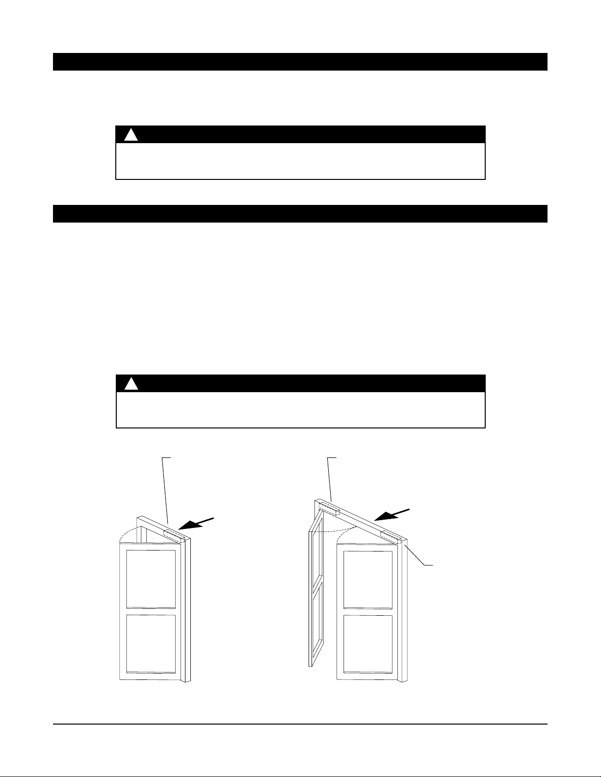
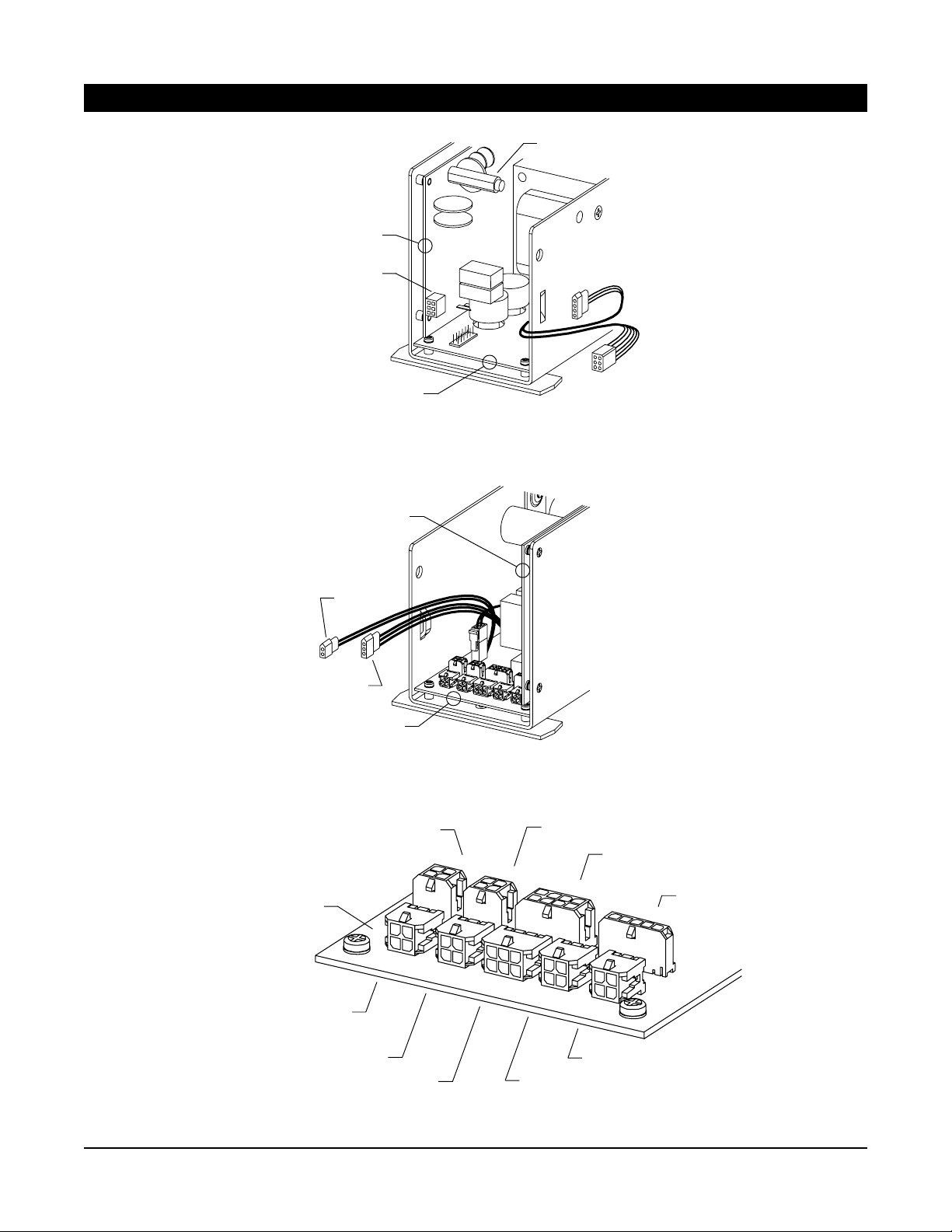
• See Figure 3-2, Figure 3-3, and Figure 3-4 for names and locations of control box connectors.
• See Figure 3-5 for control box plug and jack descriptions, wiring, and mating cables.
• See Figure 3-6 for electric strike locking device sample wiring.
• See Figure 3-7 for EL (electric latch retraction) locking device sample wiring.
!
When joining or separating a plug and receptacle, do not push or pull on wires. This
may cause a wire to be pulled loose from a terminal, which may result in a malfunction.
CAUTION
Connect operator for second door to control
box Companion Motor Power receptacle
(P5 on control box power board)
Approach
side
Connect master
operator to control
box Master Motor
Power cable
Safety
side
Connect single door
operator to Master
Motor Power cable
from control box
Approach
side
Safety
side
Figure 3-1
Page 4 of 14 740100-00(5)
Page 5
POWER
BOARD
Companion
motor power
(P5)
3. WIRING (continued)
AC fuse, 120 VAC
2.5 A time-delay
AC
power
LOGIC BOARD
Master motor
Figure 3-2. Control box power board connectors.
POWER BOARD
Breakaway
3-position
switch
LOGIC BOARD
See Figure 3-4 for
closeup of control
box logic board
connectors
Figure 3-3. Control box logic board connectors.
DMSS (companion; approach side)
LOGIC BOARD
P5
P4
DMSS (companion; safety side)
P10
power
Locking Interface and
Power Boost disable input
Retrofit
Accessories
P8
P3
DMSS (master; approach side)
DMSS (master; safety side)
Bodyguard (safety side)
P2
P1
P6
Activate
P7
Activate
Figure 3-4. Closeup of control box logic board connectors.
740100-00(5) Page 5 of 14
Page 6

Bodyguard (master; safety side): Prevents
door from opening; holds open door in open
position (uses door state data from control box
to ignore door movement while opening/closing)
DMSS (master; safety side): Prevents door from
opening, and slows an opening door
DMSS (master; approach side): Initiates a door
opening cycle if activated while door is closing
DMSS (companion; safety side): Prevents door
from opening, and slows an opening door
DMSS (companion; approach side): Initiates a
door opening cycle if activated while door is closing
Activate: Initiates a door opening cycle
Activate: Initiates a door opening cycle
LOGIC BOARDPOWER BOARD
(operates identically to P6 and is provided as
a convenience if 2 activations are used)
Retrofit Accessories: Accesses older model
Activate, Slow/Stop, and Carpet Safety inputs
Breakaway: Disables operator inputs when
Breakaway switch is active
3-Position Switch: OFF, AUTO, HOLD
Locking Interface: Power output and relay
contacts for locking devices; Power Boost
disable input
3. WIRING (continued)
P1
on-board
connector
P2
on-board
connector
P3
on-board
connector
P4
on-board
connector
P5
on-board
connector
P6
on-board
connector
P7
on-board
connector
P8
on-board
connector
permanent
connections
permanent
connections
P10
on-board
connector
If used
If used
If used
If used
If used
If used
If used
Retrofit
only
If used
Cable
761468
Safety
Approach
Safety
Approach
Cable
761464
Cable
761464
Cable
761469
Cable
761465
Bodyguard
JST-type
connector
Black, 24 VAC
Red, 24 VAC
White, Slowdown
DMSS
harness
761467
DMSS
harness
761467
Black, 24 VAC
White, 24 VAC
Yellow, Activate
Gray, Ground
Black, 24 VAC
White, 24 VAC
Yellow, Activate
Gray, Ground
Blue, Carpet Safety
Gray, Ground
Yellow, Activate
Violet, Slowdown
Orange
Black
Red
Green
Black
Blue, Power Boost disable
Black, Ground
Violet, Relay NO
Gray, Relay COM
Brown, Relay NC
Green, 5 V
White, 24 VAC
White, 24 VAC
Green, Ground
Black, 24 VAC
Red, 24 VAC
White, Activate
Green, Ground
Black, 24 VAC
Red, 24 VAC
White, Slowdown
SafetyApproach SafetyApproach
Green, Ground
Black, 24 VAC
Red, 24 VAC
White, Activate
Green, Ground
Bodyguard cable
to Bodyguard
sensor
T o DMSS
(master;
safety side)
T o DMSS
(master;
approach side)
T o DMSS
(companion;
safety side)
T o DMSS
(companion;
approach side)
Used only for powered activation device
Activate cable
T o normally open Activate contacts
Used only for powered activation device
Activate cable
T o normally open Activate contacts
To existing cable
710057 (old part
No. 81276)
To normally closed
Breakaway switch
or jumper 81269
To 3-position
switch (if used)
Ground
To normally open
Power Boost
disable contacts
To locking device
(see page 7 for
sample wiring)
To motor cable of
Companion Motor Power: Companion motor
power (use only for second door of simultaneous
pair or independent pair of doors)
P5
on-board
connector
If used
Cable
761466
companion operator
(use only for second
door of simultaneous
pair of doors)
To motor cable of
Master Motor Power: Master motor
power (use for single door)
AC Input: 120 VAC
permanent
connections
permanent
connections
Cable
761463
Black, Hot AC
White, Neutral AC
Green, Earth Ground
master operator
(always use for
single door)
To 120 VAC
Figure 3-5
Page 6 of 14 740100-00(5)
Page 7

3. WIRING (continued)
!
Always wire the locking device to the NO (normally open) contact of the control box locking interface
and use the keypad to set the EL (electric lock) setting to either SA (fail safe) or SE (fail secure).
Control box lock supply rating: 24 V AC, 1.5 A
Middle or Senior Swing
control box
The keypad EL (electric lock) setting is SA (fail safe). When the operator is on, the strike is locked when
the door is closed and unlocked when the door is opening. When the 3-position switch is set to OFF , the
strike is unlocked.
NOTE
Cut connector off rectifier , then
connect using wire nuts
White
White
Gray (COM)
Violet (NO)
Cable 761465 to Middle or
Senior Swing control box locking
interface receptacle (P10)
White
White
Rectifier
(for DC
strikes)
Black
Red
Fail safe
electric
strike
Figure 3-6. Sample Wiring for a Fail Safe Electric Strike Locking Device
Cable 761465 to Middle or
Senior Swing control box locking
interface receptacle (P10)
Gray (COM)
Violet (NO)
Middle or Senior Swing control box
When using an EL device such as EL33A, EL99, etc:
Use 12 A WG stranded wire for outputs 01 and 02
between PS873 and EL device (200’ run maximum).
EL device
The keypad EL (electric lock) setting is SE (fail secure). The control box locking relay signals the PS873
x 871-2. When the operator is on, the EL device is locked when the door is closed and unlocked when the
door is opening. When the 3-position switch is set to OFF, the EL device is locked.
Von Duprin
PS873 x 871-2
SC I1 O1 GND
Figure 3-7. Sample Wiring for a Fail Secure EL (Electric Latch Retraction) Locking Device
740100-00(5) Page 7 of 14
Page 8

4. KEYPAD SETTINGS
Settings (except for close speed) for the Middle and Senior Swing Power Operator System are changed using
keypad pushbuttons and an alphanumeric display on the Astro Swing control box (Figure 4-1 and Figure 4-2).
Close speed is changed using dials on the control box (Figure 4-1).
See page 9 and page 10 for directions for changing the values of settings.
!
Adjust the operator for the slowest operation practical in accordance with the latest
revisions of Americans with Disabilities Act, ANSI/BHMA A156.19 (American National
Standard for Power Assist and Low Energy Power Operated Doors), and local codes.
CAUTION: 120 VAC
2.5 A TIME-DELAY FUSE
WARNING: FOR CONTINUED
PROTECTION AGAINST FIRE,
REPLACE ONLY WITH SAME
TYPE AND RA TING OF FUSE.
COMPANION MASTER
COMPANION
MOTOR
Close speed dials
S
L
O
W
CLOSE
SPEED
CAUTION
SETTING
: OPENING SPEED
: BACKCHECK SPEED
: BACKCHECK POS.
: HOLD-OPEN DELAY
UP
Parts Inside
F
S
A
L
S
O
T
W
CLOSE
SPEED
No Serviceable
F
A
S
T
DOWN
: LATCH POSITION
: AUTO-REV . CLOSING
: ELECTRIC LOCK
: POWER BOOST
: PUSH ‘N’ GO
: ALTERNATE ACTION
: SAFETY SLOW/STOP
: SLOWDOWN DISABLE
: RESERVED
VALUE
UP
DOWN
DEFAULT
POWER
ON
XXXX SWING
WARNING: ALL SPEED
SETTINGS (OPENING,
CLOSING , AND LATCHING)
AND HOLD-OPEN TIMEDELAY MUST BE FIELD
ADJUSTED TO MEET
LATEST APPLICABLE ANSI/
BHMA ST ANDARDS.
LCN
XXXX-00
SN: XXXX
#2
DMSS
#2
DMSS
ELECTRIC
APPROACH
SAFETY
LOCK
RETROFIT
®
Keypad
P5
P4
P10
P8
#1
DMSS
APPROACH
#1
DMSS
SAFETY
BODYGUARD
ACTIVATE
ACTIVATE
P3
P2
P1
P6
P7
Figure 4-1. Control Box Panel with Keypad
Setting display
SETTING VALUE
V alue display
Reset to default
values pushbutton
DEFAULT
: OPENING SPEED
: BACKCHECK SPEED
POWER
ON
: BACKCHECK POS.
Setting selection
pushbuttons
UP UP
DOWN DOWN
: HOLD-OPEN DELA Y
: LATCH POSITION
: AUTO-REV . CLOSING
: ELECTRIC LOCK
: POWER BOOST
V alue selection
pushbuttons
: PUSH ‘N’ GO
: ALTERNA TE ACTION
: SAFETY SLOW/STOP
: SLOWDOWN DISABLE
: RESERVED
Figure 4-2. Closeup of Control Box Keypad
Page 8 of 14 740100-00(5)
Page 9

4. KEYPAD SETTINGS (continued)
!
W ARNING
KEEP HANDS, CLOTHING, WIRES, TOOLS, LADDERS, ETC. A WAY
FROM THE DOOR WHEN THE OPERATOR IS INITIALLY TURNED ON.
See Figure 4-3 for definitions of the positions of the door throughout the opening and closing cycle.
See Table 4-1 for explanations of the keypad settings.
T o change setting values:
1. Set the 3-position switch, if used, to OFF.
2. Apply AC power . The POWER light will illuminate and the display will remain blank.
3. Press any two pushbuttons at the same time for 1 second to turn on the keypad. The display will illuminate.
4. Press the UP or DOWN setting selection pushbutton to select the desired setting. The setting is
shown in the SETTING display , and the current value for that setting is shown in the V ALUE display .
5. Press the UP or DOWN value selection pushbutton to select the desired value for the displayed
setting. The value for the setting is indicated in the V ALUE display.
6. The keypad will automatically turn off after 5 minutes of inactivity .
To reset all values to default (default values are listed in Table 4-1 under “Selectable Values”):
1. Set the 3-position switch, if used, to OFF.
2. Apply AC power . The POWER light will illuminate, and the display will remain blank.
3. Press any two pushbuttons at the same time for 1 second to turn on the keypad. The display will illuminate.
4. Press the DEFAULT pushbutton for 4 seconds.
5. The values are set to default, and the display will indictate the opening speed setting and value.
6. The keypad will automatically turn off after 5 minutes of inactivity .
Back check speed
Back check position
Opening
speed
Closing
speed
Latch position
Deceleration to fully
closed position
Figure 4-3. Door Position Definitions
740100-00(5) Page 9 of 14
Page 10

4. KEYPAD SETTINGS (continued)
Safety side Door Mounted Safety Sensor (DMSS) disable feature
Purpose:
Deactivate the Door Mounted Safety Sensor (DMSS) on safety side of door to eliminate
nuisance detection of a wall or guard rail.
1. Install control box, all door hardware and safety devices per their instructions.
2. Setup DMSS sensors in accordance with ANSI standard 156.10.
3. Use keypad to set SAFETY SLOW/STOP (SS) value to STOP (SP).
4. Use keypad to set SLOWDOWN DISABLE (SD) value to 85.
5. Activate door opening cycle. If door does not open fully, use keypad
to reduce SD value from 85 in 5 degree increments.
6. Repeat Step 5 until door opens fully.
7. Perform a complete system test as described in the section 5.
Wall
Safety side
DMSS Sensor
Door
DMSS Sensor
Frame
(85 degrees or less)
Active Sensor
Page 10 of 14 740100-00(5)
Page 11

4. KEYPAD SETTINGS (continued)
T able 4-1. Control Box Settings and Selectable V alues
Setting
Opening Speed
back check Speed
back check Position
hold open delay
Latch Position
Auto reverse Closing
Electric Lock
Setting
Display
Selectable
Values
01 = slow
02 = medium
03 = fast
(default = 01)
01 = 1 door
02 = 2 doors
(default = 01)
45-80 degrees
(default = 70)
01-32 seconds
(default = 05)
00-23 degrees
(default = 13)
off, on
(default = off)
off
SA = fail safe
SE = fail secure
(default = off)
Values as
Displayed
Description
Controls opening speed of any normal
weight and size door
Controls speed of door near full open
position to prevent door slamming open
Approximate angle at which door begins
to decelerate near the full open position
Amount of time (in seconds) door remains
fully open following an activate signal
Approximate angle at which door begins
to decelerate near the full closed position
When on, door will re-open upon hitting
an obstruction
To turn on, set to SA (fail safe) or SE (fail
secure) to match locking device connected
to control box locking interface receptacle
(P10); when on, causes a 1 second delay
between activate signal and door opening
to allow time for most electric locks to
disengage before operator opens door
Power boost
Not functional on
Middle Swing
control box
Push ‘N’ Go
off
5 seconds
continuous
(default = off)
off, on, fd
(default = off)
off, on
Alternate Activate
Safety Slow/Stop
(default = off)
slow, stop
(default = slow)
Slowdown disable
740100-00(5) Page 11 of 14
off , 30-85
(increments of 5)
When on, increases closing force of door
from 9 lbs to 18 lbs to close door against
high winds or stack pressure; turns on
for 5 seconds or continuously after door
reaches latch position during closing cycle;
disabled by Power Boost disable input
When set to On or Fd, pushing door
open 5 degrees causes operator to open
door remainder of way and hold open.
Hold open time is same as hd setting
when set to On. Hold open time is 1
second when set to Fd.
When on, door stays open until a
second activate signal is received
Determines response to a DMSS on the
safety side of the door; if SL (slow),
door goes to back check speed; if SP
(stop), door stops for 5 seconds, then
continues opening at back check speed
Used when DMSS detects nearby wall or
guard rail while opening. Set to highest
approximate angle that normal door
operation will allow. When enabled,
slowdown ignored at all angles greater
than value displayed.
ReservedReservedReserved
Page 12

5. SYSTEM TEST
!
KEEP HANDS, CLOTHING, WIRES, TOOLS, LADDERS, ETC. AWAY
FROM THE DOOR WHEN THE OPERATOR IS INITIALLY TURNED ON.
If control box does not operate as expected during system test, see section
6 for troubleshooting tips.
5.1. With the door closed, set the 3-position switch, if used, to AUTO and turn on all AC power.
For applications using companion door , try to get both doors to open same amount of
degrees before hitting hard stop (either internal gearbox stop or rubber bumper on wall).
5.2. Activate the operator using an activation device. The operator should perform one
sizing cycle.
Sizing Cycle: Occurs when the door is activated for the first time after power is
turned on. During the sizing cycle, the door opens and closes once.
If the door sizes properly , go to step No. 5.3.
If the door does not open at all during the sizing cycle:
• Check that the 3-position switch, if used, is not set to OFF .
• Check door for binds and proper mechanical installation.
WARNING
• Verify that all safety sensors are inactive.
• If an electromechanical lock is used, check that the lock disengages before
the operator opens the door .
• Verify that the Breakaway switch, if used, is connected to NC contact s. If a
Breakaway switch is not used, check that the Breakaway cable coming from
the control box logic board is jumpered (jumper part No. 81269).
• Check fuse, wiring, and connections.
• Adjust the operator as follows and check door operation:
Opening speed:................. 01
Back check speed:............ 01 for one door, 02 for two doors
Hold open delay:................ 05
Back check position: ......... 75
Latch position: ................... 10
Close speed:..................... medium
Electric lock: ...................... SA (fail safe) or SE (fail secure) to match lock
If the door does not open fully during the sizing cycle, check door for binds,
obstructions, or items that could activate safety sensors.
Page 12 of 14 740100-00(5)
Page 13

5. SYSTEM TEST (continued)
5.3. After the sizing cycle is complete and the door is closed, apply a maintained activation
signal and check that the door remains open while the activation signal is applied.
Then release the activate signal and verify door closes after the open time delay expires.
5.4. T o check the function of the door safety device:
5.4.1. Activate the door and then activate the approach side safety device while the
door is open. The door should not close while the safety device is activated.
Next, deactivate the safety device. The door should close after the hold open
time delay expires.
5.4.2. With the door closed, activate the safety side safety device, then activate the
door. The door should not open while the safety device is activated. Next,
deactivate the safety device. The door should open when activated.
5.5. Set the 3-position switch, if used, to HOLD. Verify that the door opens and stays open.
5.6. Set the 3-position switch, if used, to OFF. V erify that the door closes. Verify that an
activate signal does not open the door.
5.7. If a Breakaway switch is connected, set the 3-position switch, if used, to AU TO, then
break open the door. V erify that an activate signal does not cause the door to move.
Re-latch the door after testing.
5.8. Do not release the system for service until it is operating properly.
6. TROUBLESHOOTING
6.1.
Identify all switch and sensor inputs that are currently active:
6.1.1. Remove breakaway jumper to enter diagnostic mode.
Note: When in diagnostic mode, controller will not open door .
6.1.2. Keypad display shows each active input signal for 1 second. See table below:
(Key switch) set to Auto OR is not present SA80
(Key switch) set to OFF SA81
(Key switch) set to HOLD SA82
(Activate) input is ON SA83
(DMSS approach) activate input is ON SA84
(DMSS safety) slowdown input is ON SA85
(Carpet Safety) input is ON SA86
(Bodyguard) input is ON SA87
(Power Boost Disable) input is ON SA88
For example, if key switch is set to Auto, Activate button is pressed, and
DMSS sees something on the safety side, then display will repeat the
sequence SA80, SA83, SA85 continuously until breakaway jumper is replaced.
6.1.3. After completing diagnostics, reinstall breakaway jumper for normal operation.
740100-00(5) Page 13 of 14
Page 14

6. TROUBLESHOOTING (continued)
6.2.
If control box does not function and the error message Er## flashes on the control
box Setting and V alue displays, turn AC power of f and on to reset the control box.
The following are common errors and suggested fixes:
ER 06: Master motor problem - verify master motor cable is connected to motor.
ER 14: Companion door added to a setup that was already sized - turn AC
power off, then on and resize with both doors connected.
If problem cannot be corrected by using suggested fixes, contact 1-800-526-2400.
7. RELEASE FOR SERVICE
7.1. Remove all tools, installation equipment, and debris from the vicinity of the door .
7.2. Inst all all safety , traffic control, and instruction decals on the door as required by the
latest revision of ANSI/BHMA A156.19. This is very important! Failure to do this
leaves the installer LIABLE for any accident that might occur . This must be done!
7.3. V erbally instruct the owner or person in charge of the proper operation of the door .
7.4. Instruct the owner or person in charge to routinely inspect the door for the following:
• Visible damage
• Developing problems
• Minor preventive maintenance
7.5. Instruct the owner or person in charge who and where to call for service when required.
!
Make sure to install all safety, traffic control,
and instruction decals on the door as required.
IMPORTANT
Page 14 of 14 740100-00(5)
 Loading...