

Page 1
Installation Instructions
®
931224-00
6221 Electric Strike
Double Door Open Back Mortise or Cylindrical Application
89/336/EEC
Notes: Deadbolt will not function with this strike.
Check with factory for retrofit applications.
1. For lock or device preparation, see their directions.
2. Prepare door for strike (see other side).
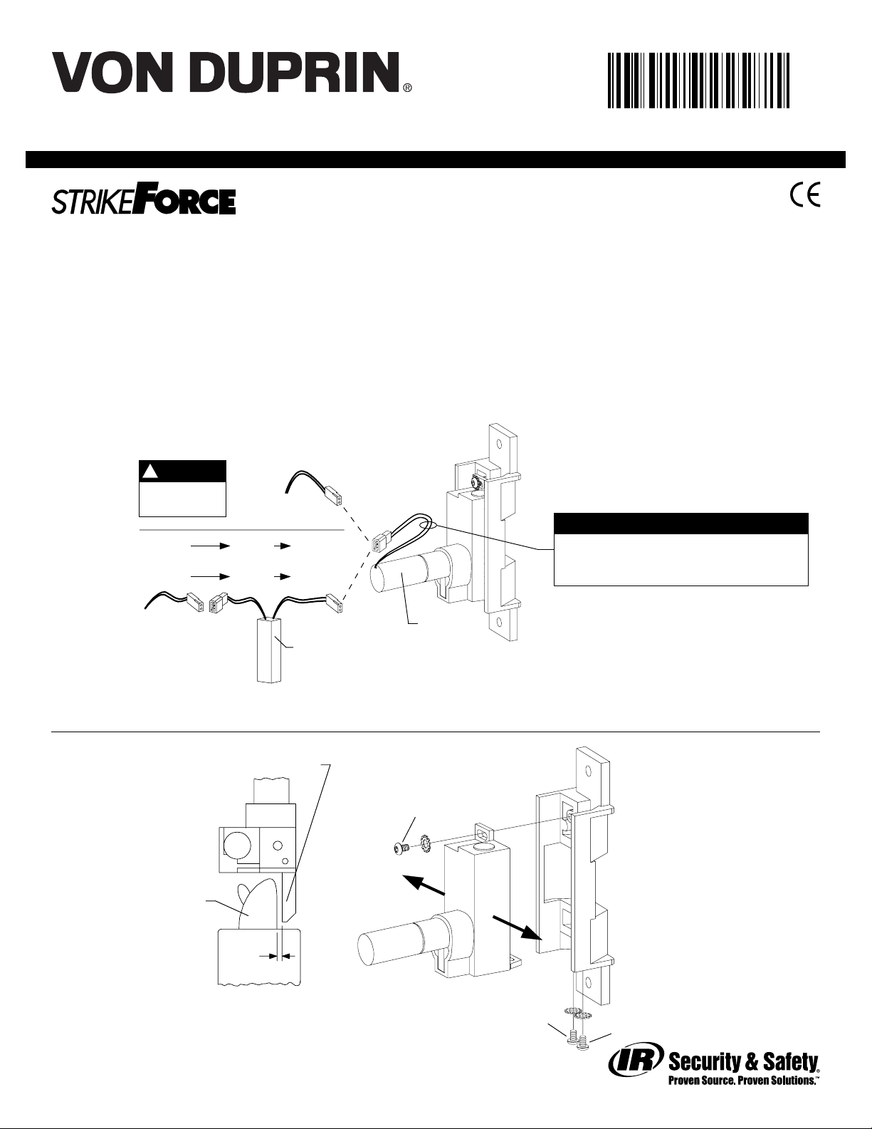
3. Wire strike (Figure 1).
NOTE
Wiring
for DC
supply
Wiring
for AC
supply
connectors to
splice field wiring
to P1 leads
!
DC input is
{
nonpolarized.
12 VAC SO-12 12 VDC
or
24 VAC SO-24 24 VDC
{
Use crimp
P1 J1A P1A
12 VDC
or
24 VDC
P1
SO-12 or SO-24
J1
4. Test strike: Apply solenoid power. Fail secure (FSE) lip unlocks.
Fail safe (FS) lip locks.
5. Install strike with two #12-24 screws. Make sure clearance
between latch bolt and strike lip is 1/32” (Figure 2). If not,
uninstall strike, adjust (Figure 3), and reinstall.
6. Test door: With strike unlocked, door opens with latch bolt
extended. When door closes, latch bolt rides over strike lip.
931224_5931224_5
931224_5
931224_5931224_5
PREPUBLICATION
REVIEW COPY REV. A
SOLENOID POWER REQUIREMENTS
Yellow solenoid wires = 12 VDC, 0.57 A
Black solenoid wires = 24 VDC, 0.29 A
(also shown on strike label)
Solenoid
Figure 1
Strike lip
A
Latch bolt
1/32”
Top view;
faceplate not
shown for clarity
Figure 2
931224_00(5) Copyright © 2004 Ingersoll-Rand. All rights reserved.
To adjust strike,
loosen screws A, B,
and C and move
backbox sideways
as necessary
B
C
Figure 3
Page 2
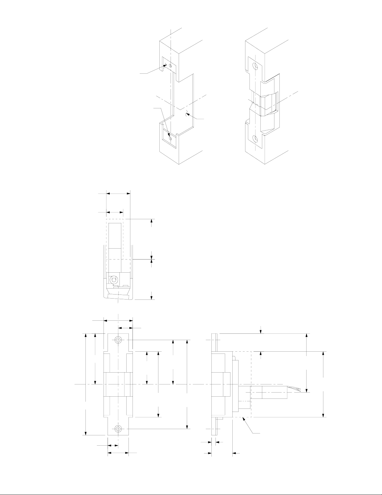
Reinforce for strike
attachment as required
1-7/16” minimum
clearance
LHR shown
RHR opposite
RHR door
shown inactive
#16 drill and
#12-24 tap
2 places
C door
L
C strike
L
Suggested
cutout
Door Preparation for Strike
1” dia. minimum
clearance
Strike
backbox
assembly
1-3/4”
C strike
L
and
latch bolt
6”
3”
C of door
L
1-15/16”
2-3/8”
minimum
clearance
2-3/8”
minimum
clearance
7/8”
3-7/8”
2-5/8”
1-1/16”
3-1/2”
3-7/8”
5-1/4”
931224_00(5)
5/8”
1/4”
1-1/4”
1-1/4”
Strike Dimensions and Required Clearances
Minimum
clearance
 Loading...