

Page 1
®
VON DUPRIN
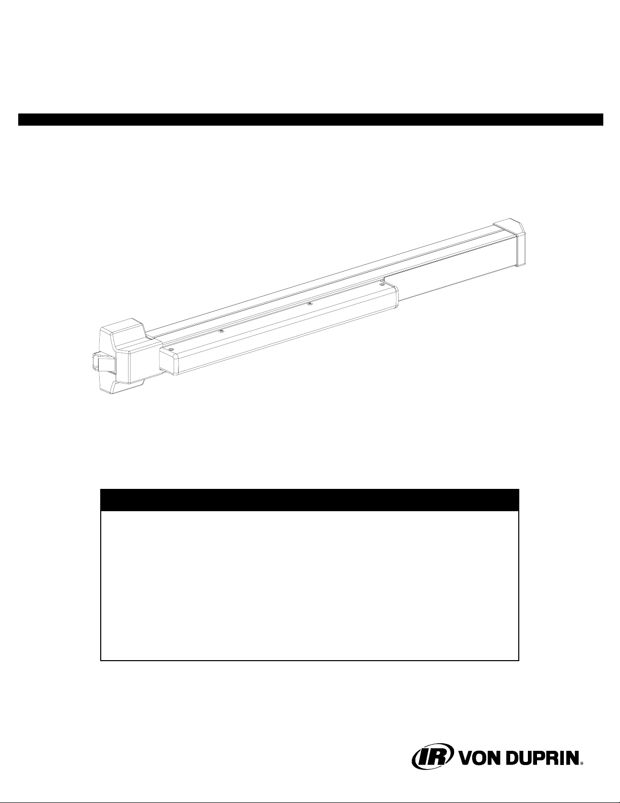
Installation Instructions
22 Rim Device
Devices covered by these instructions:
22 Rim Device
22-F Fire Exit Rim Device
BEFORE STARTING INSTALLATION
1. Check hardware schedule for strikes, fasteners, and other special requirements.
2. Check carton label for trim, strikes, options, and order number.
3. Read all instructions, including instructions provided with any options used:
trim, alarm kit, glass bead kit, latch guard kit, and rod guard kit.
4. Gather special tools required: • #10-24 tap • 13/32” dia. drill bit
• #25 drill bit • Hacksaw
• 1/8” dia. drill bit • 7/8” dia. hole saw
• 1/4” dia. drill bit
This product is covered by the following patent numbers:
3,767,238 4,167,280 4,427,223 4,437,693 4,466,643
Copyright © 2003 Ingersoll-Rand. All rights reserved.
911333_00(9)
Page 2
GENERAL INFORMATION
Review pages 2 and 3 so you can identify the hardware and understand the terminology used in the instructions.
See page 10 for the “Metric Conversion Table” if needed.
These exit devices can be installed on the door widths listed below:
Device Size
Code/Standard Requirement
Door Size
Standard 3’ (32”) NFPA101 24-3/4” to 36”
Standard 4’ (44”) NFPA101 30-3/4” to 48”
!
NOTE
Dogging panic device during high traffic periods
will increase life of device. To dog, depress pushbar
and turn hex key one-quarter turn clockwise.
MAINTENANCE
Von Duprin 22 exit devices are designed and built to be maintenance free; however, such factors
as installation, severity of use, environmental conditions, and changes in the condition of the door
opening may require that maintenance and/or device adjustment be performed. The following
guidelines are recommended to the building owner to insure proper device operation:
1. Check device operation for smooth operation periodically.
2. Check strikes (keeper) and latches to insure they are secure.
3. Check latches and other moving parts for binding or sluggish operation due to dirt or chemical
buildup. Clean parts with soap and water and then lubricate with graphite-based or silicone
lubricants. Do not use petroleum-based lubricants.
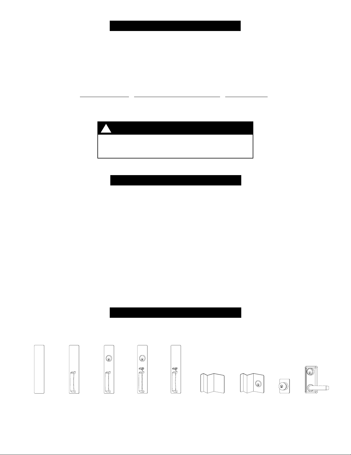
OUTSIDE TRIM
No outside trim supplied for EO (exit only) application
Escutcheon
(optional for
EO application)
911333_00(9) Page 2 of 12
DT
(pull when
dogged)
NL
(key retracts
latch bolt)
TP
(key locks
thumbpiece)
TP-BE
(thumbpiece;
unlocked)
DT
(pull when
dogged)
NL
(key retracts
latch bolt)
K
(key locks
knob)
L
(key locks
lever)
Page 3
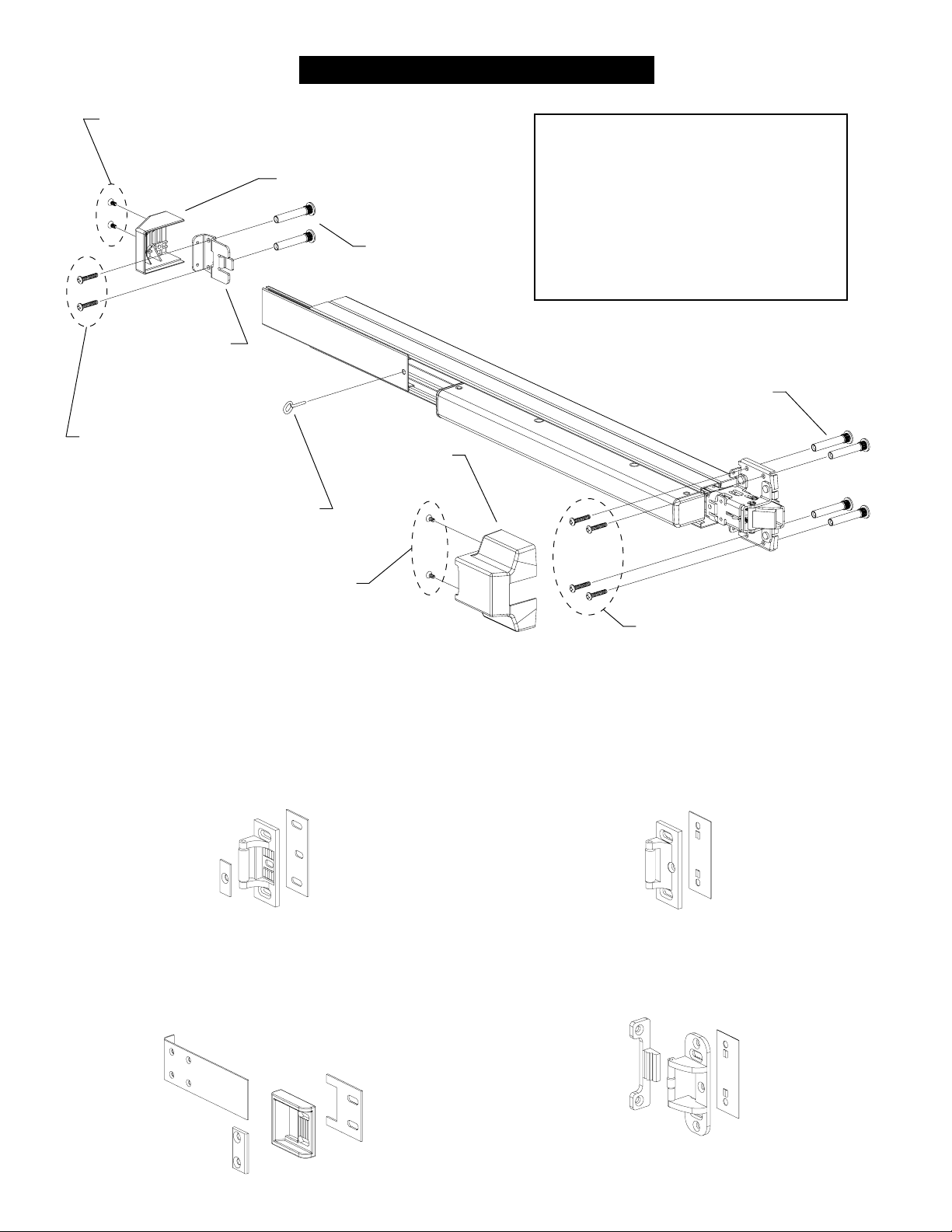
22/22-F PARTS LIST
#8-18 x 1/2” undercut flat head machine screws
(from mechanism end cap package)
Mounting Screw Package
Mechanism case end cap
Mechanism
case mounting
bracket
From mounting
screw package
Dogging key
(panic device)
#8-18 x 1/2” undercut
flat head machine screws
(from mechanism end cap package)
#425 sex bolts
(optional)
Center case
cover
#10-24 x 3/4”machine screws (2)
#10-24 x 1”machine screws (6)
#10-24 x 1-1/8”machine screws (2)
#10-24 x 1-1/2”machine screws (6)
#10 x 1-1/4”sheet metal screws (8)
#425 sex bolts
(optional)
From mounting screw package
Strike Packages
299 Strike Package
(panic device)
#10-24 x 3/4” machine screws (3)
#10 x 1-1/2” wood screws (3)
Strike
Strike
plate
1409/1439 Strike Package (1409 shown)
(panic device, aluminum frame, 1/2” blade stop)
#10-12 x 10-24 x 1-1/4” combinartion screws (2)
Flat head drive rivets (4)
Wear strip
Strike
Adjustment
block
Shim
Shim
299F Strike Package
(fire exit device, single door)
#10-24 x 3/4” machine screws (3)
#10 x 1-1/2” wood screws (3)
Strike
Shim
499F Strike Package
(fire exit device, double door)
#10-24 x 3/4” machine screws (7)
Strike
Strike
hook
Shim
911333_00(9) Page 3 of 12
Page 4
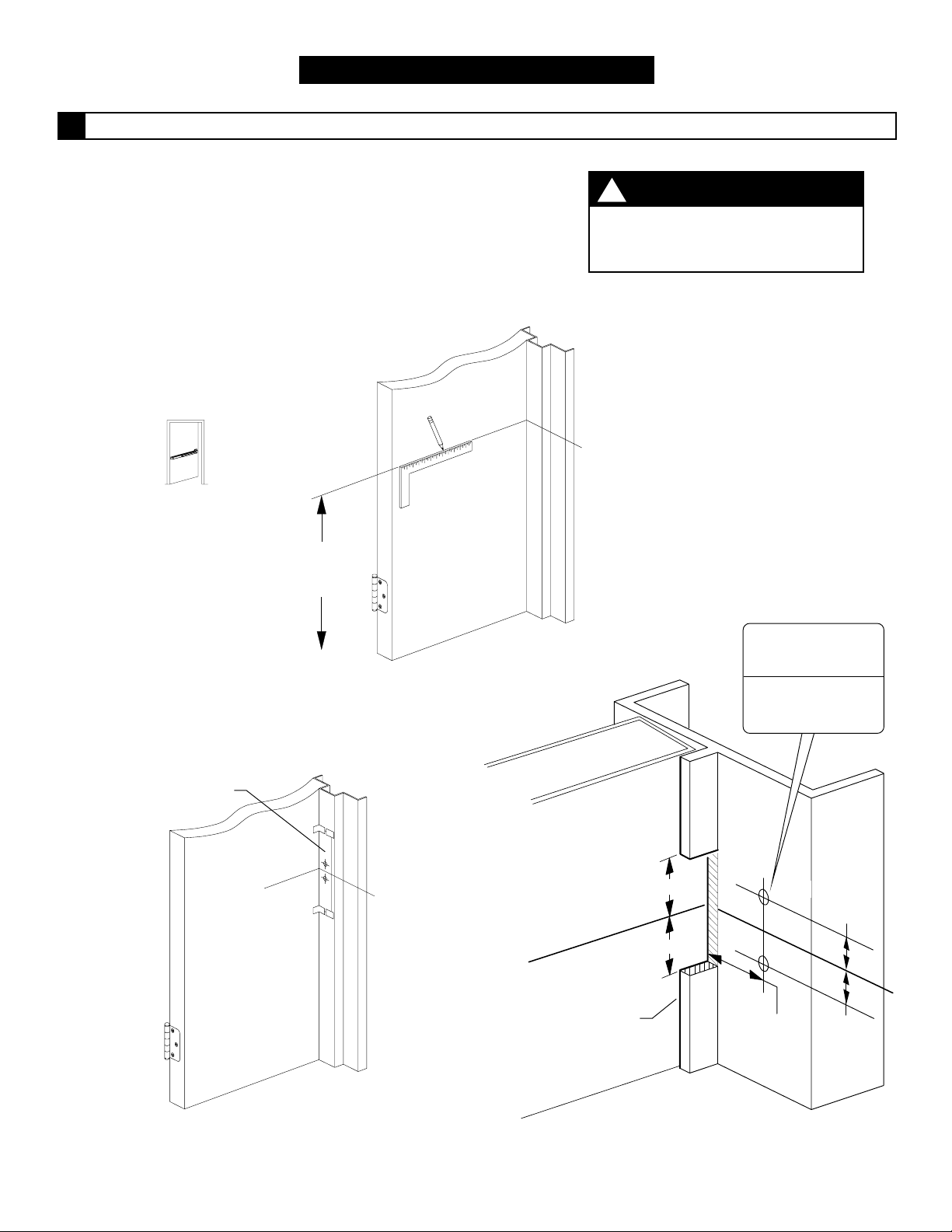
INSTALLATION
For single door, prepare frame for 299, 299F, 1409/1439 strike.
1
1.1. Mark centerline C location as shown in Figure 1-1.
L
1.2. For 299 or 299F strike: Tape strike template to frame
aligned with center line C as shown in Figure 1-2.
L
Mark and prepare mounting holes per template.
For 1409/1439 strike: Prepare frame as shown in Figure 1-3.
RHR shown
C
L
LHR opposite
39-13/16”
to finished
floor
!
NOTE
For double door, mullion is
already prepared for 499F strike.
Skip this step and go to Step #2.
Template
C
#25 Drill
#10-24 tap
MetalWood
Figure 1-1
1/8” Drill pilot
1” deep
Cut -out
L
C
L
Blade stop
7/8”
7/8”
C
L
1-9/16” to
face of
door
7/16”
7/16”
Figure 1-2. 299 or 299F Strike
911333_00(9) Page 4 of 12
Figure 1-3. 1409/1439 Strike
Page 5

Install strike. Use TWO SCREWS ONLY at this time.
2
299 (shown)
or 299F Strike
499F Strike
Door
Door
Stop
Use screws from 299/299F
strike package
#10-24 flat head machine
3/4”
for metal frame
#10 flat head wood
1-1/2”
for wood frame
Use screws from 499F
strike package
#10-24
flat head machine
3/4”
Install strike flush with door side
of stop for 1409 and 1/16” past
door side of stop for 1439
1409/1439
Strike
(1409 shown)
1409/1439
Wear Strip
Door side
of stop
Wear
strip
Mullion
Use screws from
1409/1439 strike package
#10-12 x 10-24 oval
head combination
1-1/4”
1. Center wear strip on strike as shown.
2. Mark and drill 1/8” dia. holes (4 places).
3. Install wear strip with flat head drive rivets
(4 places) from 1409/1439 strike package.
911333_00(9) Page 5 of 12
Page 6

Cut device if necessary.
3
3.1. Device length A must be at least 1-1/2” shorter than B .
A
B
Measure from
inside of stop
Measure from end of center case cover
(not from tip of latch bolt)
3.2. If necessary, cut device so A is at least 1-1/2” shorter than B .
Cover plate flush
with end of pushbar
!
If using ALK exit alarm option, install
ALK cover plate before cutting device.
Tape
Cover plate
Measure
from strike
NOTE
Pushbar
Prepare door for device.
4
4.1. Cut center case template for 1409/1439
strike or for 299/299F/499F strike.
4.2. Tape center case template to inside of door
aligned with center line C as shown.
4.3. Mark and prepare holes per template.
4.4. Prepare door for outside trim (see trim
instructions).
RHR shown
LHR opposite
911333_00(9) Page 6 of 12
L
Place cut edge of
template against stop
C
L
299/299-F/499-F Strike 1409/1439 Strike
C
L
Page 7

Install device to door at center case.
5
5.1. If using cylinder in trim, install tailpiece guide (packaged with trim) in device.
Device cylinder cam
Bottom of
center case
Align tailpiece guide
to match tailpiece
5.2. Install device to door at center case.
Tailpiece guide
Tailpiece
Use screws from device mounting screw package
1”
#10-24 pan head machine
for
metal door surface mount,
sex bolts on 1-3/4” door, or
outside trim on 1-3/4” door
1-1/2”
#10-24 pan head machine
for
sex bolts on 2-1/4” door or
outside trim on 2-1/4” door
#425 sex
bolts (shown)
or outside trim
optional
1-1/4”
#10-24 pan head sheet metal
for
wood door surface mount
911333_00(9) Page 7 of 12
Page 8

Install mechanism case mounting bracket and mechanism case end cap.
6
Slide in
1
mechanism
case mounting
bracket
Bracket flush against
mechanism case
Mark mounting
2
holes and prepare
per chart
Use screws from end
cap package
1/2”
#8-18 undercut flat
head machine
Device level
on door
Surface Mount
Metal Door: #25 drill and #10-24 tap inside
Wood Door: 1/8” pilot drill, 1” deep, inside
Sex Bolts
Metal Door: 1/4” drill inside, 13/32” drill outside
Wood Door: 13/32” drill thru
Install mechanism
case end cap
34
Install
mounting
screws
Use screws from device mounting screw package
3/4”
#10-24 pan head machine
for
metal door surface mount or
sex bolts on 1-3/4” door
If necessary, add strike adjusting shim under strike for 3/16” dimension shown.
7
#10-24 pan head machine
sex bolts on 2-1/4” door
3/16” between center
case cover and strike
Center case
cover
1-1/8”
#10-24 pan head sheet metal
for
wood door surface mount
1-1/4”
for
Frame
911333_00(9) Page 8 of 12
Strike
Shim
Page 9

Prepare remaining strike mounting holes and install screws.
8
299 or 299F Strike
Strike plate
(299 strike only)
Door
#25 drill and #10-24 tap,
#10-24 flat head machine
Use screw from 299/299F strike package
499F Strike
Metal frame:
1/8” drill x 1” deep
#10 flat head wood
3/4”
#25 drill and #10-24 tap,
#10-24 flat head machine
3/4”
Wood frame:
1-1/2”
Door
Strike hook
Use screws from 499F
strike package
Mullion
499F Strike Hook
Center strike hook on device 1/16” from mullion.
Clearance from
mullion
1/16”
Mullion
Inside face
of door
Strike hook
C
L
device
and strike
Mullion
Metal door:
#25 drill and #10-24 tap,
#10-24 flat head machine
3/4”
Use screws from 499-F
strike package
Wood door (#425 sex bolts):
1/4” drill inside,
13/32” drill outside
911333_00(9) Page 9 of 12
Page 10

Metric Conversion Table
inches mm inches mm inches mm inches mm inches mm inches mm
1/16 2
1/8 3
3/16 5
1/4 6
13/32 10
7/16 11
1/2 13
5/8 16
3/4 19
7/8 22
125
1-1/16 27
1-1/8 29
1-1/4 32
1-1/2 38
1-9/16 40
1-11/16 43
1-3/4 45
2-1/4 57
24-3/4 629
30-3/4 781
32 813
36 914
39-11/16 1008
39-13/16 1011
44 1118
48 1219
911333_00(9) Page 10 of 12
Page 11

STRIKE TEMPLATE
Refer to Step 1 (p. 4)
when using this template
C device
L
CENTER CASE TEMPLATE
Template to scale
(dimensions in inches)
LHR
5/8”
1-1/16”
C
L
Refer to Step 4 (p. 6)
when using this template
Template to scale
(dimensions in inches)
5/8”
5/8”
LHR
1-11/16”
C
L
1-1/16”
Prepare holes 2 places:
Metal frame:
#25 drill and #10-24 tap
Wood frame:
1/8” drill x 1” deep
Cut strike template along
this line and place on stop
with this edge against door
7/8” dia. for
NL, K, L, and
TP trim only
Prepare holes 4 places:
Surface Application (no outside trim):
Metal door: #25 drill and #10-24 tap inside
Wood door: 1/8” drill x 1”deep pilot holes
#425 Sex Bolts or Outside Trim:
Metal door: 1/4” drill inside and 13/32” outside
Wood door: 13/32 drill thru
Cut on this line for 1409/1439 strike
For 1409/1439 strike cut center case template along
this line and place on door with this edge against stop
For 299/299F/499F strike place center case
template on door with this edge against stop
1-11/16”
911333_00(9) Page 11 of 12
Page 12

C device
L
STRIKE TEMPLATE
Refer to Step 1 (p. 4)
when using this template
911333-00
RHR
1-11/16”
C
L
CENTER CASE TEMPLATE
Refer to Step 4 (p. 6)
when using this template
Template to scale
(dimensions in inches)
5/8”
5/8”
Template to scale
(dimensions in inches)
RHR
5/8”
1-1/16”
C
L
1-11/16”
7/8” dia. for
NL, K, L, and
TP trim only
Prepare holes 4 places:
Surface Application (no outside trim):
Metal door: #25 drill and #10-24 tap inside
Wood door: 1/8” drill x 1”deep pilot holes
#425 Sex Bolts or Outside Trim:
Metal door: 1/4” drill inside and 13/32” outside
Wood door: 13/32 drill thru
For 1409/1439 strike cut center case template along
this line and place on door with this edge against stop
For 299/299F/499F strike place center case
template on door with this edge against stop
1-1/16”
Prepare holes 2 places:
Metal frame:
#25 drill and #10-24 tap
Wood frame:
1/8” drill x 1” deep
Cut on this line for 1409/1439 strike
Cut strike template along
this line and place on stop
with this edge against door
911333_00(9) Page 12 of 12
 Loading...