

Page 1
Installation Instructions
FIG:LONOpt
This equipment has been tested and found to
This Class (A) digital apparatus meets all t he
Installation Instructions
Issue Date April 9, 2014
FX Supervisory Controller LON Card
Application
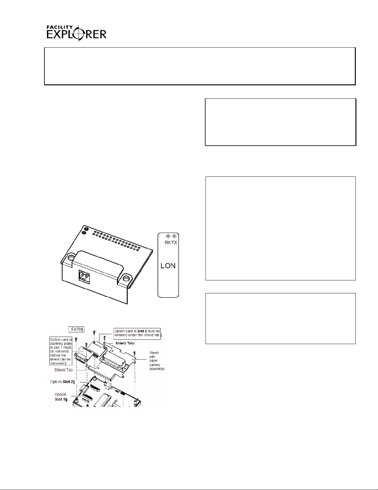
The FX Supervisory Controller LON Option Card
provides L
(FTT)-10A communications capability to the FX
Supervisory Controllers (FX20, FX30E, FX60, FX60E,
and FX70). See Figure 1.
Up to two LON Option Cards may be installed. If one
LON Option Card is installed, it operates as LO N1,
regardless of the slot used. If two LON Opt i on Cards
are installed, LON1 is Option Slot 1 and LON2 is
Option Slot 2 (see Figure 3 for locations of opt i on
slots).
For related information on FX Supervisory Controllers
mounting and wiring, refer to the FX Superviso ry
Controllers Installation Instructions
(Part No. 24-10174-77).
ONWORKS® Free Topology Transceiver
IMPORTANT: For the FX70, carefully pry up the
shield tab to install the option card under the tab. Do
not install the Option Card in slot 2 with the card
resting on top of the shield tab. Otherwise, an
electrical short or some other issue from m isali gned
card header pins may result.
North American Emissions Compliance
United States
comply with the limits for a Class A digital device
pursuant to Part 15 of the FCC Rules. These lim i ts
are designed to provide reasonable protecti on
against harmful interference when this equipm ent is
operated in a commercial environment. This
equipment generates, uses, and can radiate radio
frequency energy and, if not installed and used in
accordance with the instruction manual, may cause
harmful interference to radio communicat i ons.
Operation of this equipment in a residential area is
likely to cause harmful interference, in which case
the user will be required to correct the interference
at his/her own expense.
Figure 1: FX20/FX30E/FX60/FX60E LON Card
Figure 2: FX70 LON Card
© 2014 Johnson Controls, Inc.
Part No. 24-10174-34, Rev. C www.johnsoncontrols.com
Canada
requirements of the Canadian Interferen ce-Causing
Equipment Regulations.
Cet appareil numérique de la Classe (A) respect e
toutes les exigences du Règlement sur le matériel
brouilleur du Canada.
1
Page 2
!
Battery Assembly
(includes cable and
bracket)
Blanking
End Plate
Option Slot 1
Area
Option Slot 2
Area
Screws (4)
FX Supervisory
Controller
Installation
Parts Included
Unpack the LON Option Card and inspect the cont ents
of the package for damaged or missing components. If
any components are damaged, notify the appropriate
carrier and return them for repair or replacem ent.
Included in this package are the following items:
• one LON Option Card, along with connector end
plate
• one 2-position terminal plug for wiring to a
ONWORKS Twisted Pair/Free Topology
L
(TP/FT)-10 network
• FX Supervisory Controller LON Card Installation
Instructions (Part No. 24-10174-34)
Special Tools Needed
The following supplies and tools are required for
installation:
• #2 Phillips screwdriver: used to install the LON
card
• small flat-blade screwdriver: used for making
wiring connections to the L
Safety Precautions
The following information relates to the installation and
startup of the LON Option Card.
ONWORKS network
IMPORTANT: Avoid hot plug-in or removal of any
option card from the FX Supervisory Controlle rs; that
is, do not remove any card with power applied. If the
unit switches to battery operation, wait for al l Light
Emitting Diodes (LEDs) to go out.
Mounting
Mount the LON Option Card in either of the option
slots on the FX Supervisory Controller, as avai l able.
Follow these instructions:
1. If a station is running, stop the stat i on using the
platform Application Director view.
2. Remove power from the FX Supervisory
Controller.
3. Remove the FX Supervisory Control ler cover or
covers. Press in the four tabs on both ends of t he
controller and lift off the cover.
Note: If accessory modules are plugged into
the FX Supervisory Controller, you may need to
slide them away from the unit to access the cover
tabs.
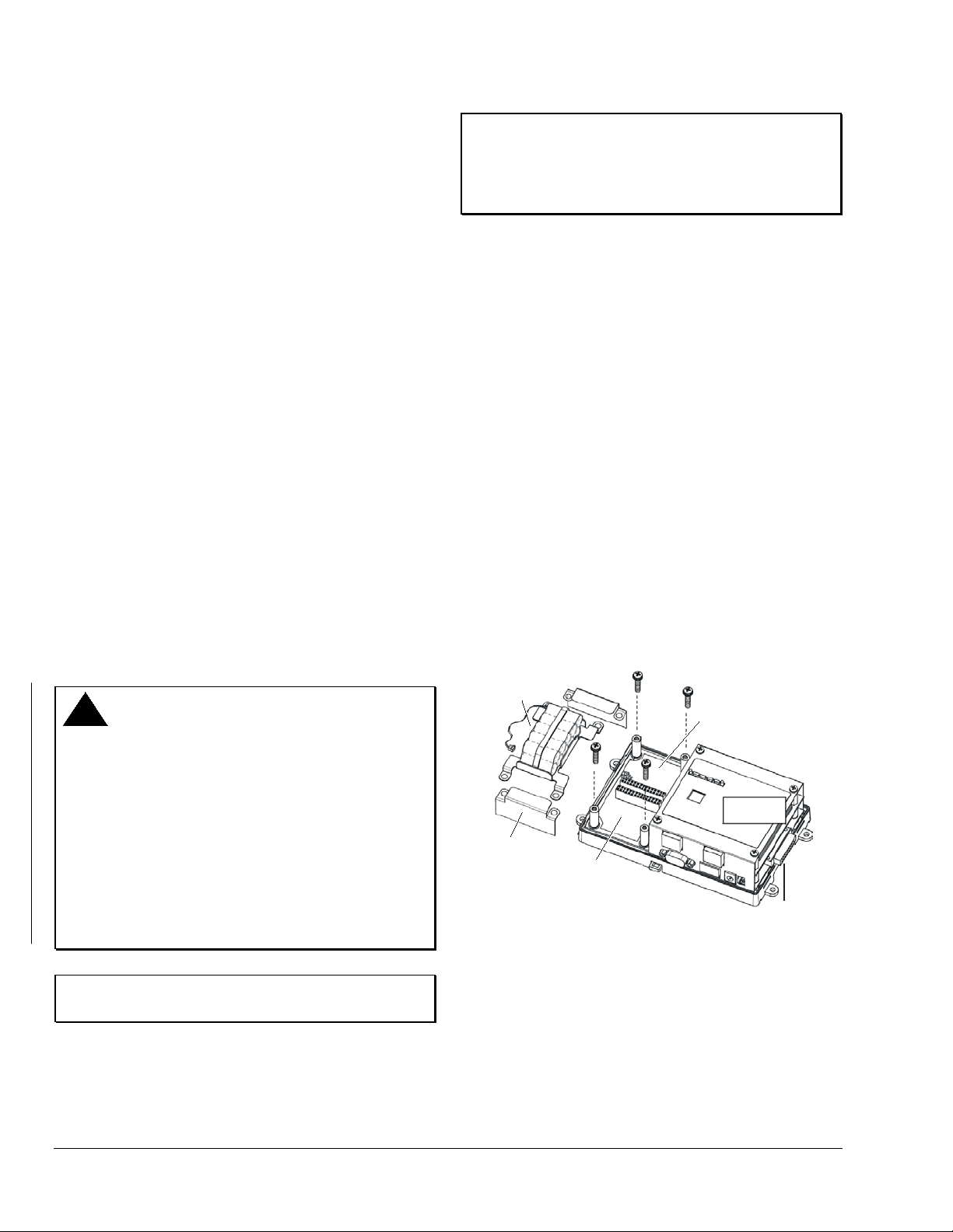
4. If the battery assembly is installed, remove it by
taking out the four screws holding it in place. Set
the screws aside for later.
5. Unplug the battery from the conne ct or on the FX
Supervisory Controller (see Figure 3).
Disconnect power supply before making electrical
connections. Contact with components carrying
hazardous voltage can cause electric shock and
may result in severe personal injury or deat h.
AVERTISSEMENT: Risque de décharge
électrique Débrancher l'alimentation avant de
réaliser tout branchement électrique. Tout contact
avec des composants conducteurs de tensions
dangereuses risque d'entraîner une décharge
électrique et de provoquer des blessures grav es,
voire mortelles
IMPORTANT: Be careful to plug any option card
into its connector properly (pins aligned).
2 FX Supervisory Controllers LON Card Installation Instructions
WARNING: Risk of Electric Shock.
Figure 3: Removing Battery Assembly
6. Remove the blanking end plate for the slot into
which you are installing the Option Card. Retain
the blanking end plate in case you need to
remove the Option Card at a later date.
Page 3
Insert LO N card
int o opti o n c ar d slo t
carefully with pins aligned.
Fully sea t c ard.
P la ce LO N car d c ust om
en d plate over end.
FX S upervisory Controller
Battery Connector
FIG:FasnScrws
Lightly tighten the
four screws into the
standoffs by going
through the battery
bracket and end plates.
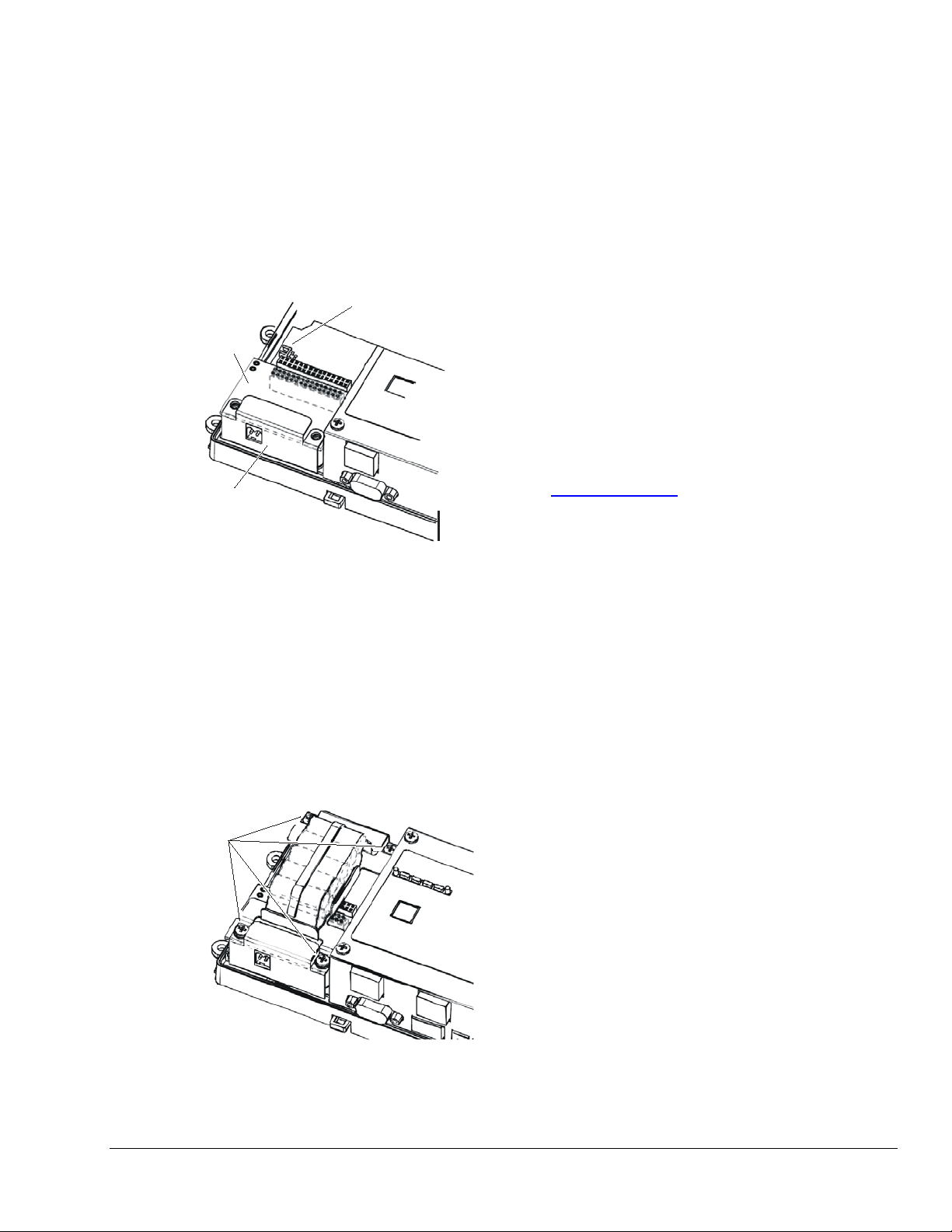
7. Carefully insert the pins of the LO N card into the
socket of the appropriate option slot. The
mounting holes on the LON card should line up
with the standoffs on the FX Supervisory
Controller. If they do not, the connector is not
properly aligned. Press until the LON card is
completely seated.
8. Place the custom end plate that came with the
LON card over its connector (see Figure 4).
Figure 4: Inserting LON Card
12. Replace the FX Supervisory Controller cover. If
accessory modules were unplugged, plug them
back into the FX Supervisory Controller as before,
and secure.
13. Restore p ower to the controller and verify normal
operation.
Wiring
Connect the LONWORKS network communications
wiring to the 2-position connector of the LON Option
Card. Polarity is not a factor with L
wiring.
Refer to the L
ONWORKS FTT-10A Free Topology
Transceiver User’s Guide (078-0156-01) for technical
guidelines associated with free topology restrictions.
Refer to the Junction Box and Wiring Guideline s f or
Twisted Pair L
ONWORKS Networks (005-0023-01) for
more detailed information on wiring specificat i ons.
These documents are available on the Echelon® Web
www.echelon.com).
site (
ONWORKS TP/FT
9. If installing/replacing the battery and bracket, plug
the battery cable into the battery connector on the
FX Supervisory Controller (see Figure 4 for
location).
10. Set the battery and bracket assembly back over
the option slots, with the mounting holes al i gned
with the standoffs.
11. Place the f our screws through the battery bracket,
through the end plates, and into the standoffs on
the FX Supervisory Controller (Figure 5). Lightly
tighten these screws with a screwdriver.
Figure 5: Refastening Screws
FX Supervisory Controllers LON Card Installation Instructions 3
Page 4

Building Efficiency
Operation
LEDs
Two LEDs are visible on the top of the LON Optio n
Card. To see them, remove the cover from the FX
Supervisory Controller. The LEDs operate as f ol l ows:
• RX (green): Receive—indicates that another
ONWORKS device is transmitting a message.
L
• TX (yellow): Transmit—indicates that the FX
Supervisory Controller is transmitting a mes sage
on the L
ONWORKS network.
These LEDs are labeled on the top of the LON card
(see Figure 1).
Repair Information
If the LON Option Card fails to operate within its
specifications, replace the unit. For a replac em ent
Option Card, contact the nearest Johnson Controls®
representative.
507 E. Michigan Street, Milwaukee, WI 53202
Johnson Controls® is a registered trademark of Johnson Controls, Inc.
All other marks herein are the marks of t heir respective owners. © 2014 Johnson Controls, Inc.
4 FX Supervisory Controllers LON Card Installation Instructions
 Loading...