

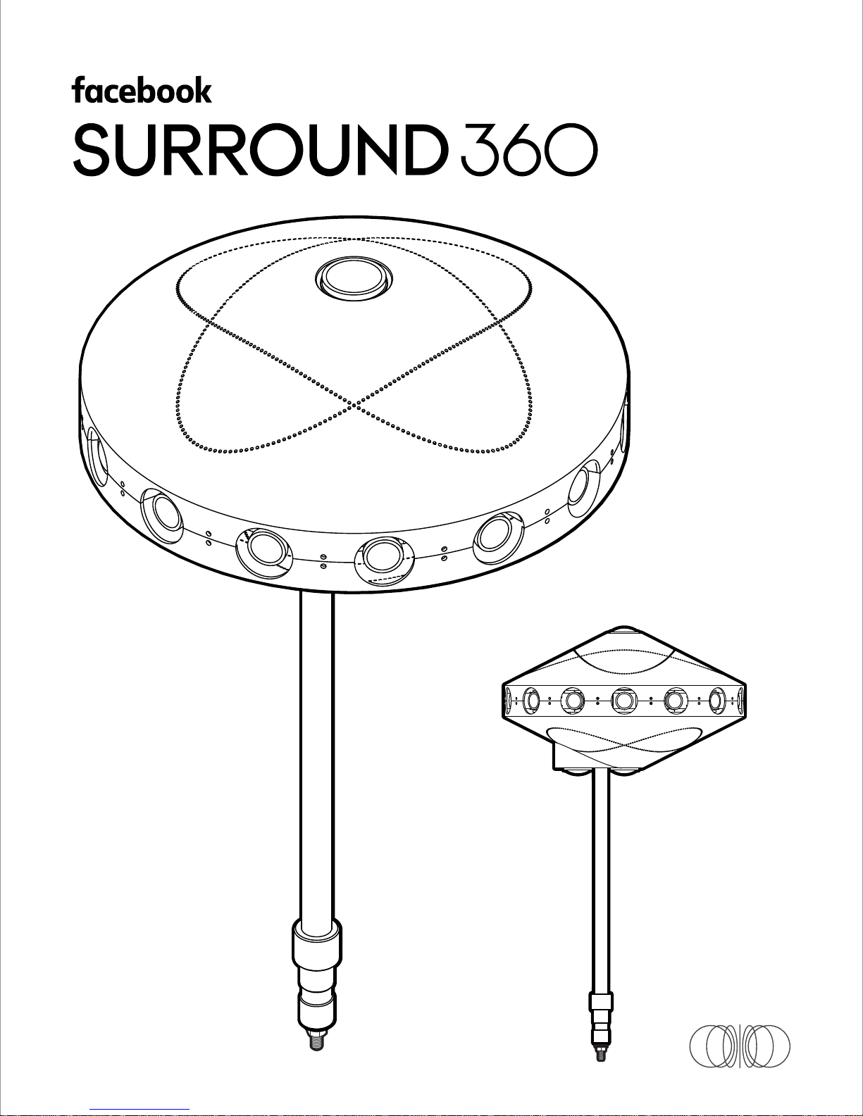
Page 1
Page 2

Page 3

Table of Contents
1. 1 - 9
Parts List
2. 1 - 6
Before You Start
3. 1 - 18
Camera Assembling Instructions
4. 1 - 2
Camera Info
5. 1 - 7
System Set Up Instructions
6. 1 - 6
Capturing & Rendering Instructions
7. 1 - 5
Pro Tips
8. 1 - 2
System Specifications
Page 4

1
Parts List
Page 5
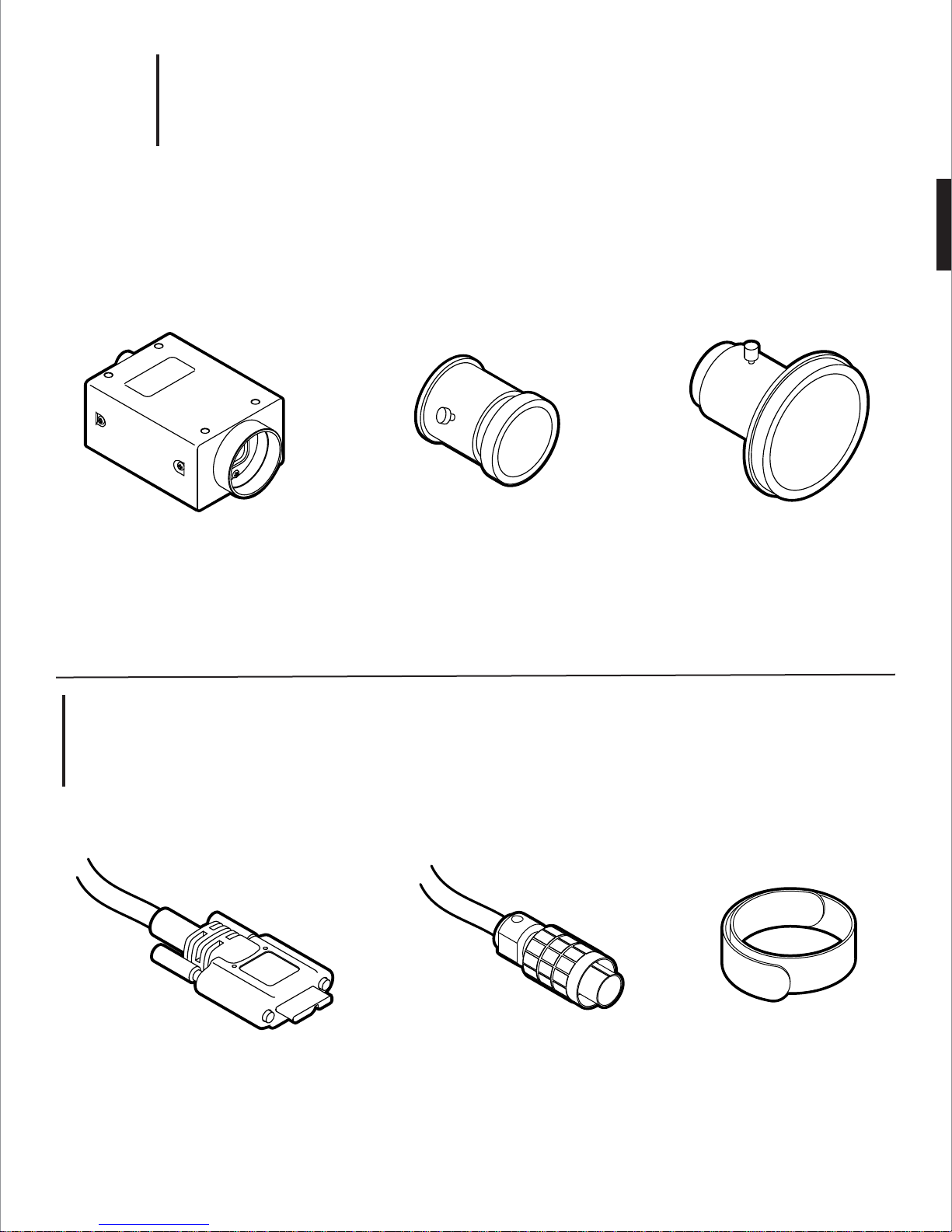
1.
1
17x
Camera Fisheye Lens
Point Grey GS3-U3-41C6C-C
Camera & Lenses
Wide-Angle Lens
with custom focusing barrel
(FB360_V1_05, _33)
Sunex DSL318B-650-F2.4
OPTIONAL:
M3 brass jam nuts (14x)
3x14x
(FB360_V1_06)
Fujinon FE185C086HA-1
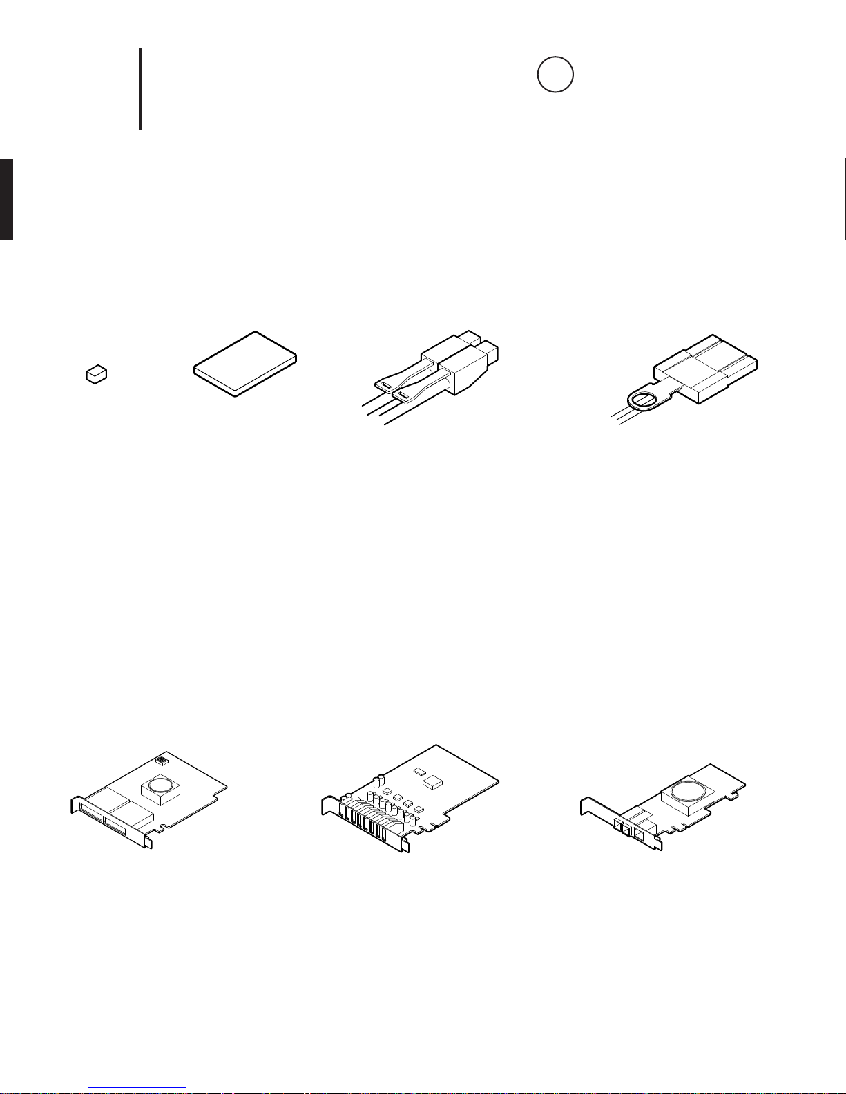
2.
Wiring
17x 17x
USB Cable GPIO Cable
Type A to Micro-B
OPTIONAL:
M2 thread, 0.4mm pitch, 20mm long
replacement screw
(FB360_V1_05, _33)
Hirose HR25 circular connector, 8 pins
Velcro Straps
Page 6
3.
1
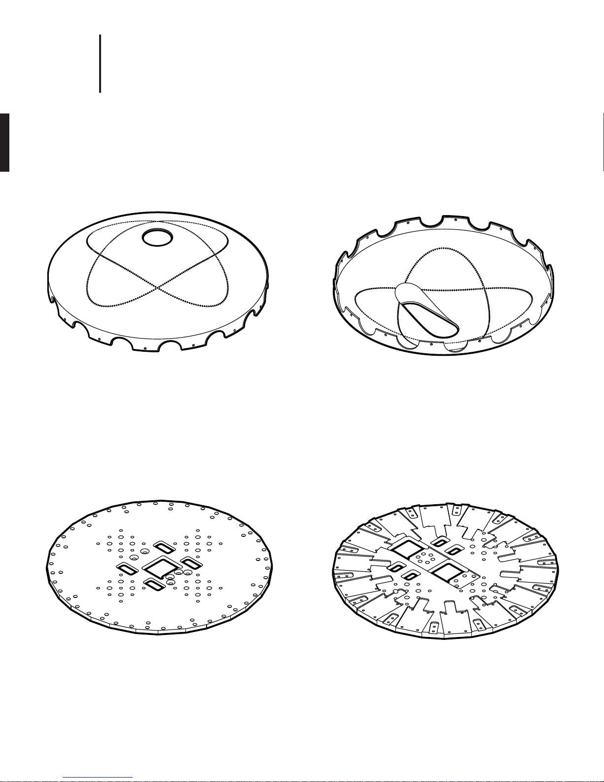
Machined Parts
1x 1x
Top Cover
(FB360_V1_30)
mild steel,
painted finish
Bottom Cover
(FB360_V1_29)
mild steel,
painted finish
1x 1x
Top Plate
(FB360_V1_22)
1/4˝ thick Mic-6 aluminum,
black anodize finish
Base Plate
(FB360_V1_21)
3/8˝ thick Mic-6 aluminum,
black anodize finish
Page 7
4.
1
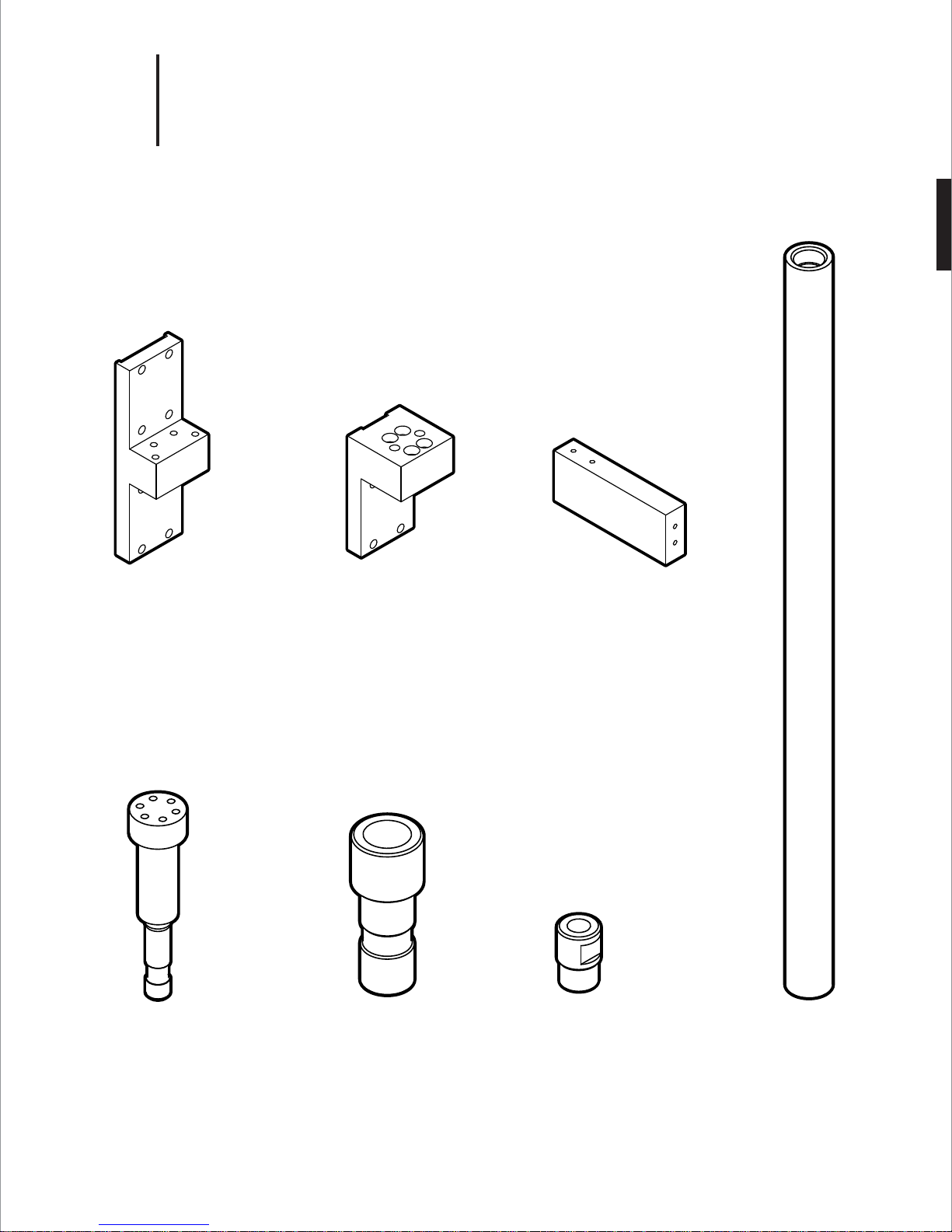
Machined Parts
1x 1x
1x
14x
Upright
(FB360_V1_23)
6061 aluminum,
black anodize finish
Camera Bracket
(FB360_V1_24)
6061 aluminum,
black anodize finish
Shell Support
(FB360_V1_28)
6061 aluminum,
black anodize finish
1x 1x 1x
Post
(FB360_V1_25)
1144 carbon steel,
black oxide finish
Adapter
(FB360_V1_27)
1144 carbon steel,
black oxide finish
Stop Nut
(FB360_V1_31)
Brass
Support Tube
(FB360_V1_26)
4130 CR tubing,
black oxide finish
Page 8
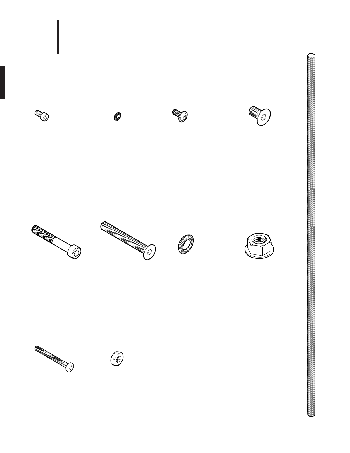
5.
1
152x
M3 Socket-Head
Cap Screw
Type 18-8 stainless steel
M3 thread, 6mm length,
0.5mm pitch
2x
Hardware
152x
M3 Belleville Spring
Lock Washer
Type 18-8 stainless steel
M3 screw size
4x
28x
M3 Flanged
Button-Head
Socket Cap Screw
Black-oxide,
M3 thread, 10mm length,
0.5mm pitch
16x
8x
M6 Flat-Head Screw
Type 18-8 stainless steel
M6 thread, 14mm length,
1.0mm pitch
1x
M6 Socket-Head
Cap Screw
Type 18-8 stainless steel
M6 thread, 40mm length,
1.0mm pitch
Optional
M2 Socket-Head
Cap Screw
Type 18-8 stainless steel
M2 thread, 20mm length,
0.4mm pitch
(replace USB locking screws)
M6 Flat-Head Screw
Type 18-8 stainless steel
M6 thread, 50mm length,
1.0mm pitch
M3 Jam Nut
Brass, M3 thread size,
5.5mm Wide, 1.8mm
High
(lock nut for Sunex barrel)
M6 Belleville Spring
Lock Washer
Type 18-8 stainless steel
M6 screw size
Steel Rotating
Flanged Nut
Black-oxide steel,
5/16"-18 thread size
3/4" flange diameter
7/16" overall height
1x
Steel Threaded Rod
(FB360_V1_32)
ASTM A193 grade B7 steel
5/16"-18 thread
20-1/4˝ long
fully threaded
Page 9
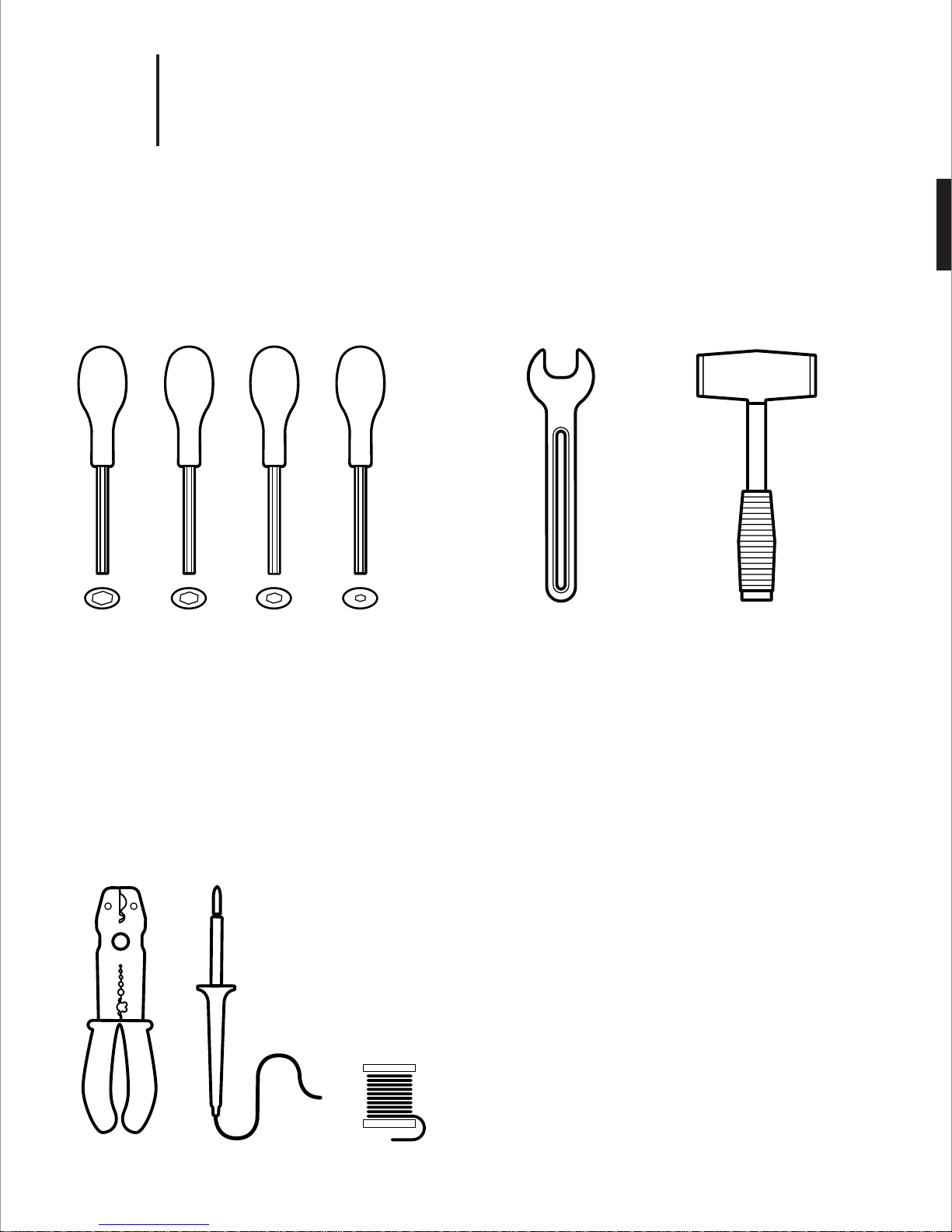
6.
1
Tools
Hand Tools
5mm
HEX
4mm
HEX
2.5mm
HEX
2mm
HEX
9/16˝
Wrench
Rubber
Mallet
Wiring Tools
Wire
Cutter
Soldering
Iron
Solder
Page 10
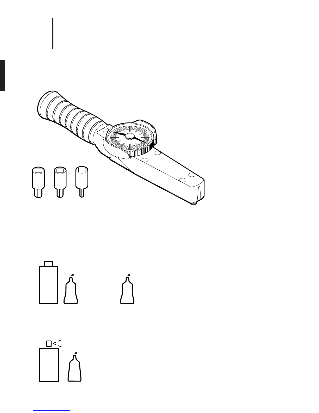
7.
1
Tools
Torque Wrench
Metric 1/4" Square Drive
Hex Bit Socket
Torque Wrench Instructions:
1. Turn the bezel until pointer is resting on zero.
2. Attach a socket or attachment to the square drive.
3. Place the socket or attachment over the fastener to be torqued.
The torque wrench handle must be perpendicular (90 degrees)
to the centerline of the drive, socket and fastener.
4. Load the torque wrench at a slow and steady rate until the pointer
indicates the desired torque.
5. Stop applying force. The pointer should return to zero.
5mm
HEX
4mm
HEX
2.5mm
HEX
Threadlockers & Adhesive
Locktite
7649
Locktite
263
PRIMER
Permanent
Threadlocker
Locktite
7075
Locktite
ACTIVATOR
Cyanoacrylate
Adhesive
RED
324
GLUE
Locktite
222
PURPLE
Removable
Threadlocker
Threadlocker Instructions:
1. Apply primer to surface of bolt and nut.
2. Apply several drops of the threadlocker onto the bolt at the nut
engagement area.
3. Assemble parts and tighten as required. Sets in approximately
10 minutes and fully cures in 24 hours.
Adhesive Instructions:
1. Apply the surface activator to both surfaces.
2. Wait 20 seconds for the activator to completely dry.
3. Apply glue sparingly to one side only using approximately one
drop per square inch of surface.
4. Press parts together immediately.
5. Hold in place for 30 seconds or until bond sets.
Page 11
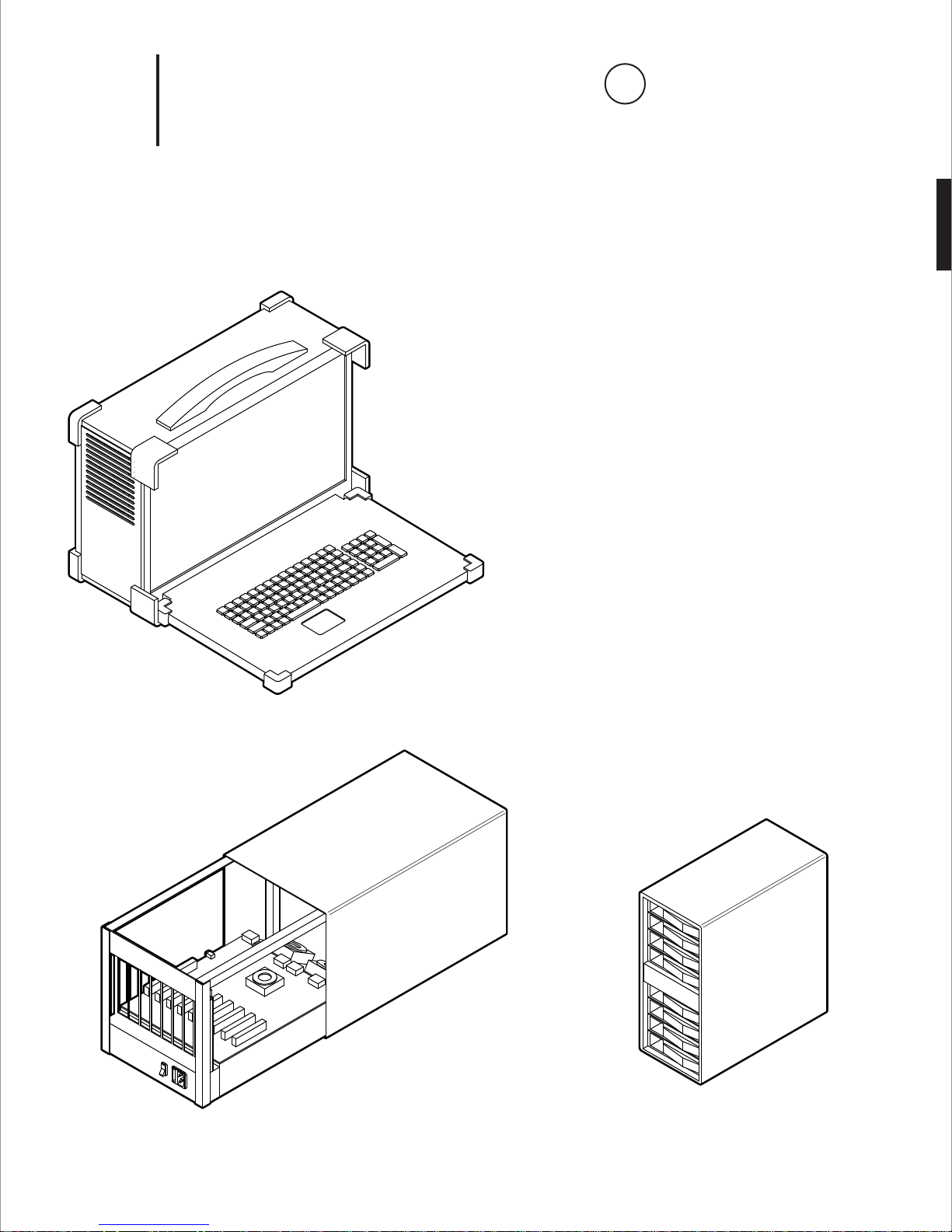
8.
Assembly Note
i
See system setup instructions for details
1
1x
Computer Hardware
Camputer - Ruggedized “Lunchbox” Computer
APOLLO-A1 MODEL
- Intel Core i7-5960X Haswell-E 8-Core 3.0 GHz LGA 2011-v3*
- GIGABYTE GA-X99P-SLI (rev. 1.0) LGA 2011-v3 Intel X99 Motherboard*
- 8GB DDR4 2400 288-PIN Memory = (64GB of Memory Installed)*
- CPU COOLING FAN FOR LGA 2011-v3*
- 1GB NVIDIA PCIe x16 VIDEO CARD*
- 700 WATT POWER SUPPLY*
- 2.5" 128GB SSD*
- OPERATING SYSTEM - UBUNTU 14.04 LTS†
1x
* Recommended
† Required
1x
PCIe Expansion Enclosure
OSS-PCIe3-ENCL-M-CUBE3-8
Expansion Backplane
OSS-BP-452
8-bay 12G SAS RAID Tower
ARC-4038
Page 12
9.
Assembly Note
i
See system setup instructions for details
1
1x
Shunt
Jumper
390088-1
Computer Hardware
8x
1TB SSD
MZ 7KE1T0BW
2x
External 4x HD Mini-SAS Cable
SFF-8644 to SFF-8644
1x
PCIe x8 Active Optical Cable
OSS-PCIe3-CBL-ACT-x8-50M-1x
2x 5x
PCIe x8 Gen 3 Cable Adapter
OSS-PCIe-HIB38-x8-DUAL
USB 3.0 Expansion Card
UE-1008 or UE-1004
1x
PCIe 3.0 x8 SAS RAID Adapter
ARC-1883X
Page 13

2
Before You Start
Page 14
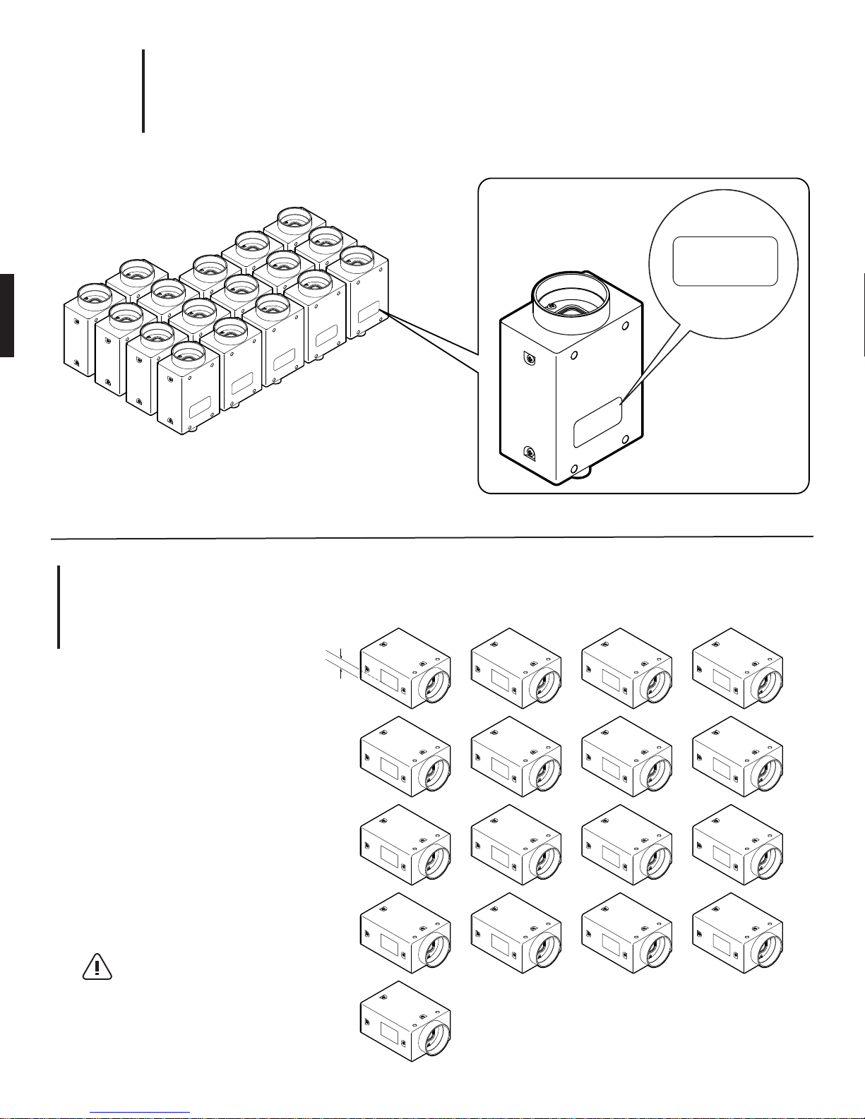
1.
2
GS3-U3-41C6C-C
XXXXXXX
Arrange Cameras in Ascending Sequential Order (Per Serial Number)
GS3-U3-41C6C-C
XXXXXXX
GS3-U3-41C6C-C
GS3-U3-41C6C-C
XXXXXXX
GS3-U3-41C6C-C
XXXXXXX
GS3-U3-41C6C-C
XXXXXXX
GS3-U3-41C6C-C
XXXXXXX
GS3-U3-41C6C-C
XXXXXXX
GS3-U3-41C6C-C
XXXXXXX
GS3-U3-41C6C-C
XXXXXXX
GS3-U3-41C6C-C
XXXXXXX
GS3-U3-41C6C-C
XXXXXXX
GS3-U3-41C6C-C
XXXXXXX
GS3-U3-41C6C-C
GS3-U3-41C6C-C
XXXXXXX
XXXXXXX
XXXXXXX
GS3-U3-41C6C-C
XXXXXXX
GS3-U3-41C6C-C
XXXXXXX
GS3-U3-41C6C-C
XXXXXXX
GS3-U3-41C6C-C
XXXXXXX
2.
Label Cameras # 00 - 16
Tip:
Keep labels 1/8” min. away
from bottom of camera to clear
mounting plate
1/8” min.
00
04
08
12
16
01
05
09
13
02
06
10
14
03
07
11
15
Page 15
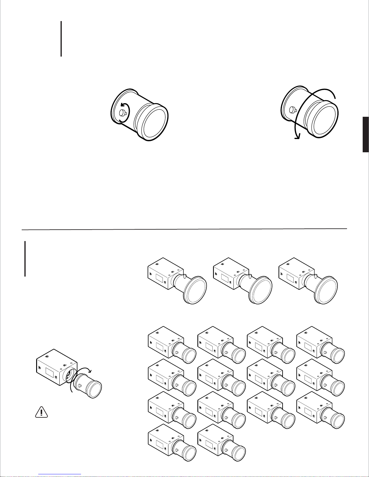
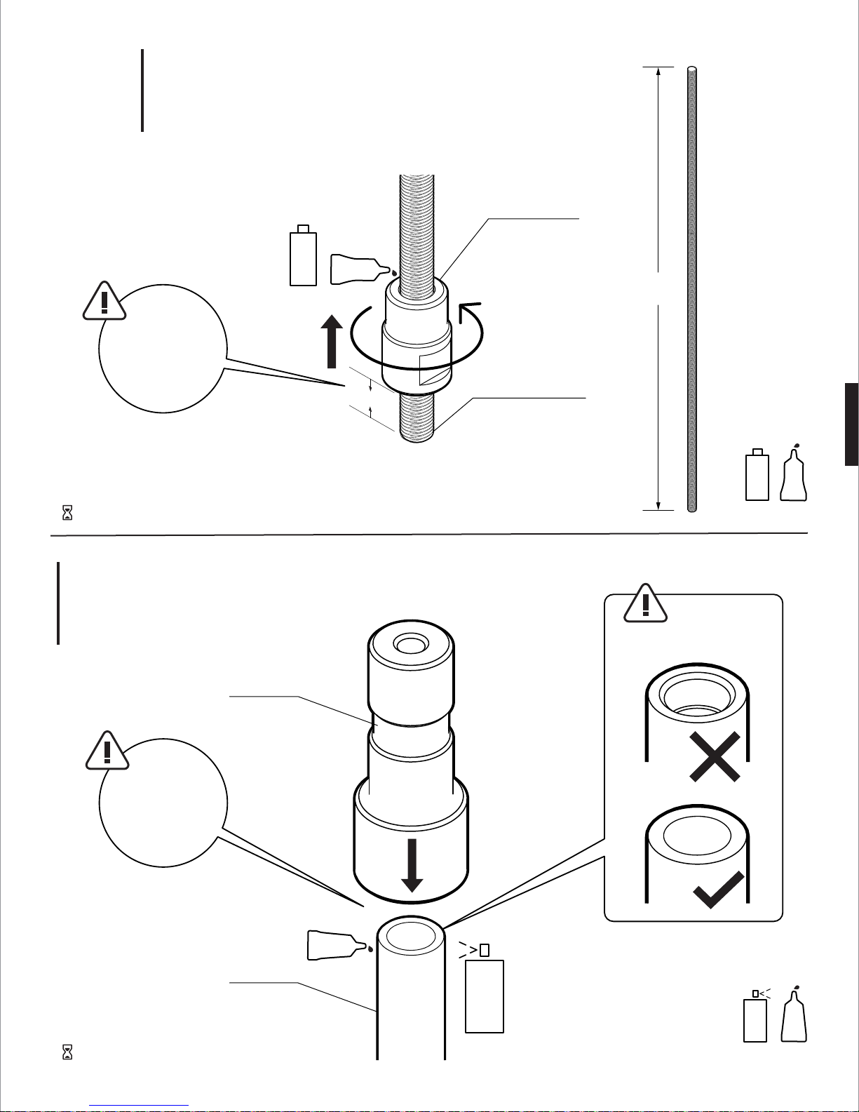
3.
2
Step 1:
Remove thumb screw
Step 3:
Screw on new focusing barrel* clockwise
and tighten thumb screw
Step 4 (Optional):
Tighten optional lock nuts (M3 brass jam nuts)
Replace Focusing Barrel of Wide-Angle Lenses (# 01 - 14)
Step 2:
Remove existing barrel
and internal spring
(counterclockwise)
* Refer to DWG FB360_V1_33
4.
Mount Lenses
Tip:
Screw lens onto camera
clockwise till its snudge
Fujinon Fisheye - # 00, 15, 16
00
Sunex Wide-Angle - # 01 - 14
01
05
09
15
02
06
10
03
07
11
16
04
08
12
13
14
Page 16
5.
2
Firmware Version Required: 2.23.3.0
Follow instructions in camera control README file
Firmware Update
6.
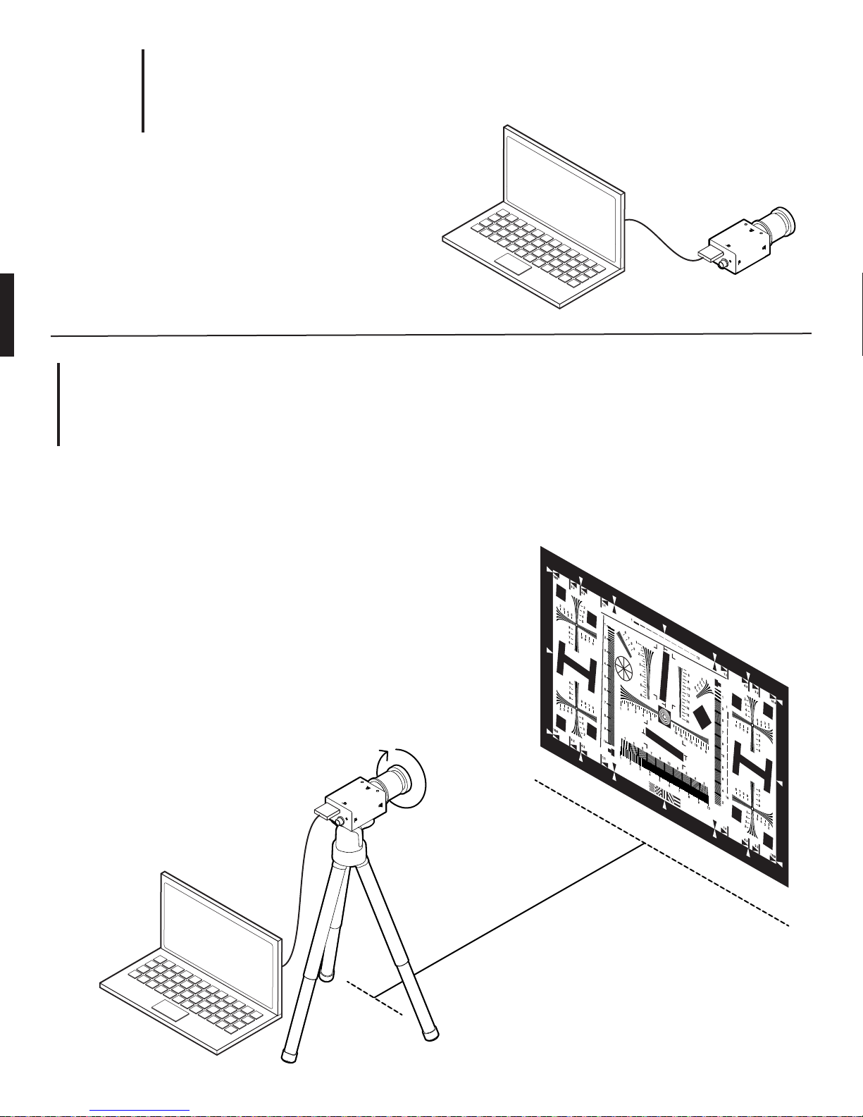
Focusing Lenses
Step 1:
Download and install FlyCapture from Point Grey (https://www.ptgrey.com/support/downloads)
Step 2:
Connect camera (with lens) to PC or Linux computer
Step 3:
Set camera on a tripod about 10 feet away from chart* on wall
Step 4:
Loosen focusing thumb screw on lens and rotate focusing barrel
till image in preview pane is sharp. Zoom in when necessary
Step 5:
Tighten focusing thumb screw
(optional: add lock nut for security)
10´-0"
* Use ISO 12233 chart or equivalent
Page 17
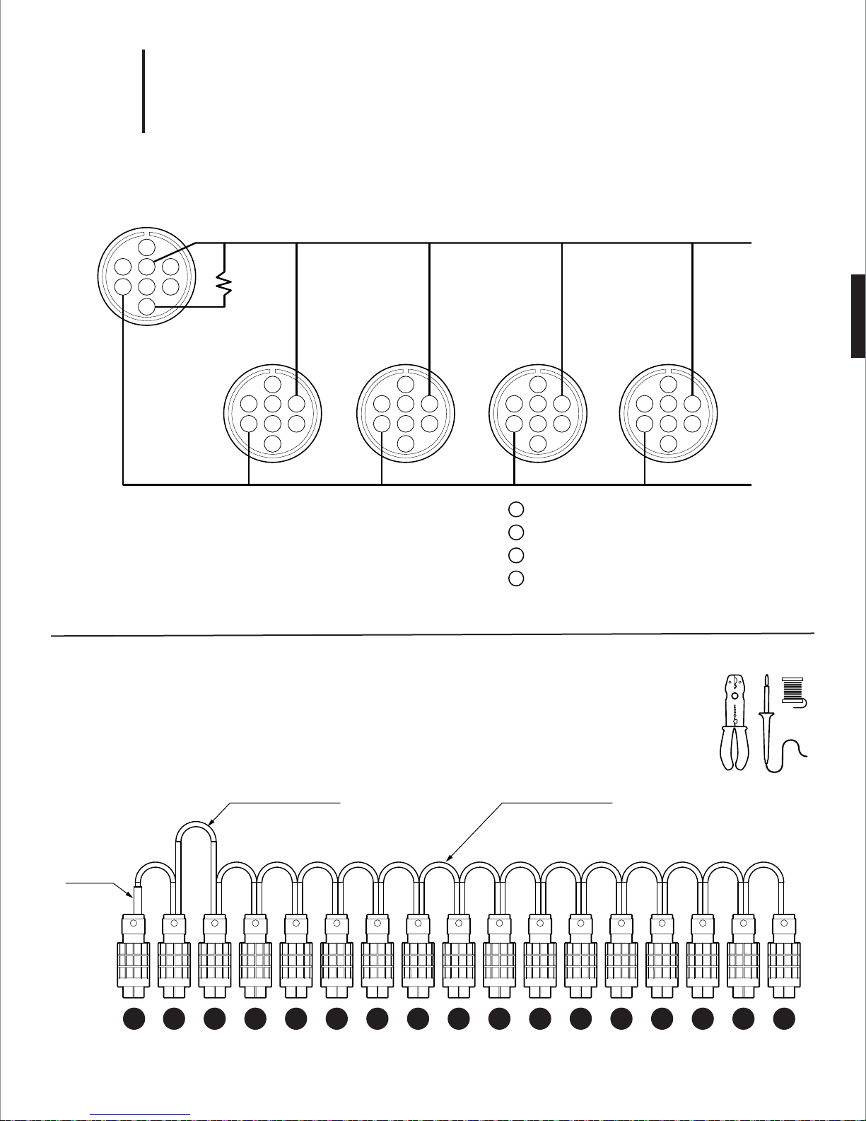
7.
2
A - Wiring Diagram
GPIO Trigger Cable
1
32 4
65 7
8
R=10K
1
32 4
65 7
8
1
32 4
65 7
8
Camera # 00 (Top) = Master Camera
Camera # 01-16 = Slave C0ameras
1
32 4
65 7
8
3
PIN IO2 - Input/Output/Serial Transmit (TX)
4
PIN
PIN
PIN
IO3 - Input/Output/Serial Receive (RX)
5
GND - Ground for bi-directional IO, V
8
+ 3.3V - Power external circuitry up to 150mA
1
32 4
65 7
8
EXT , +3.3V pins
* Refer to DWG FB360_V1_34
B - Cable Lengths From Boot to Boot
6" effective length
from boot to boot
10K
resistor
15 14 13 16 12 11 10 09 08 07 06 05 04 03 02 01
00
3" effective length
from boot to boot
* Refer to DWG FB360_V1_34
Page 18

3
Camera Assembling Instructions
Page 19
1.
3
Tip:
Leaving 1/2˝ gap at
bottom of steel rod
Set aside to wait for threadlocker to set
Screw Brass Nut Onto Threaded Rod
PRIMER
RED
1/2˝
Brass Stop Nut
Steel Threaded Rod
22-1/4˝
Locktite
7649
PRIMER
Locktite
RED
263
2.
Gluing Adapter to Tube
Adapter
Tip:
Apply glue and
activator to tube
before sliding on
adapter
Tube
Check orientation of tube
GLUE
Set aside to wait for threadlocker to set
ACTIVATOR
Locktite
7075
ACTIVATOR
Locktite
324
GLUE
Page 20
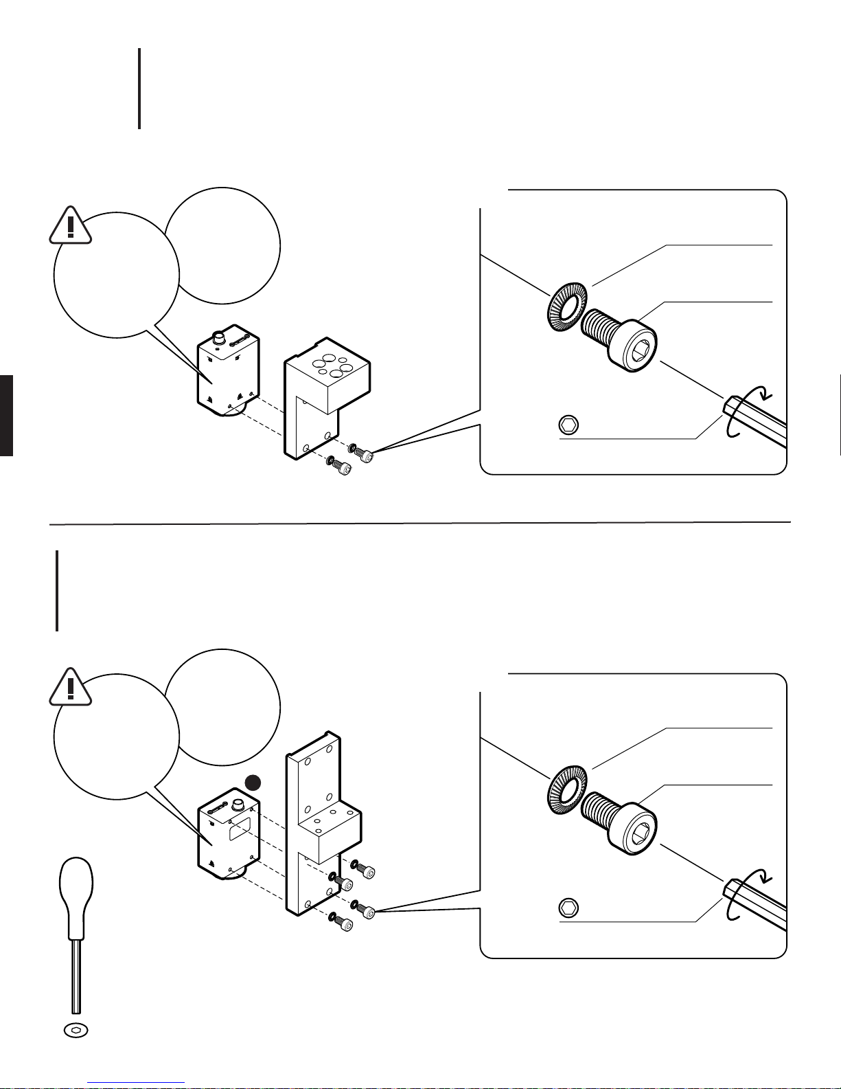
3.
3
Tip:
Mount camera #16
backward.
Use 2 M3 screws
Bottom Camera (#16) & Camera Bracket
2x
Tip:
Remove fisheye
lens from camera
Belleville Spring
Lock Washer
M3 screw size
Socket-Head
Cap Screw
M3, 6mm
2.5mm HEX
Hand tight for now,
will need to remove for wiring
4.
Bottom Camera (#15) & Upright
Tip:
Tip:
Mount camera #15
normally on upright.
Use 4 M3 screws
2.5mm
HEX
Remove fisheye
lens from camera
15
4x
Belleville Spring
Lock Washer
M3 screw size
Socket-Head
Cap Screw
M3, 6mm
2.5mm HEX
Hand tight for now,
will need to remove for wiring
Page 21
3
Tip:
Make sure flathead screws are
flush with top of
bracket
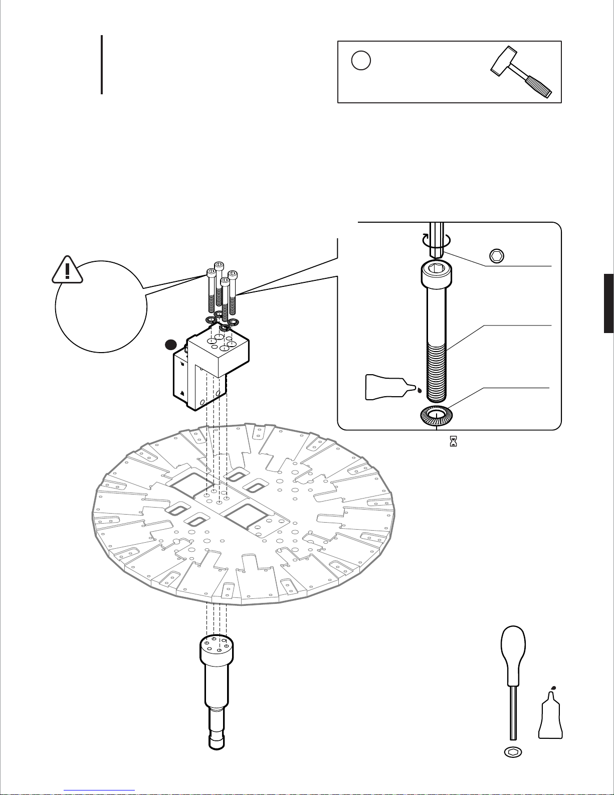
5.
Camera Bracket & Post
16
i
Assembly Note
Use a rubber mallet to gently tap
upright in place if fitting is too tight
4x
5mm HEX
Recommended
torque: 40 in-lb
Socket-Head
Cap Screw
M6, 40mm
PURPLE
Belleville Spring
Lock Washer
M6 screw size
Wait for threadlocker to set
5mm
HEX
PURPLE
Locktite
222
Page 22

6.
Assembly Note
i
Flip 180˚ to tighten screws
180˚
3
Upright
i
Assembly Note
Use a rubber mallet to gently tap
upright in place if fitting is too tight
4mm
HEX
PURPLE
Locktite
222
4x
PURPLE
Flat-Head Screw
M6, 12mm
4mm HEX
Recommended
torque: 40 in-lb
Wait for threadlocker to set
Page 23

7.
Assembly Note
i
Flip 180˚ to tighten screws
180˚
3
Side Cameras (Camera #01-14)
12
11
10
09
08
13
Camera 01 location.
Camera numbers
increase clockwise
07
14
06
01
02
03
04
05
2.5mm
HEX
56x
Belleville Spring
Lock Washer
M3 screw size
Socket Head
Cap Screw
M3, 6mm
2.5mm HEX
Recommended
torque: 15 in-lb
Page 24

8.
Assembly Note
i
Flip 180˚ to tighten screws
180˚
3
Blocks
2.5mm
HEX
28x
Belleville Spring
Lock Washer
M3 screw size
Socket-Head
Cap Screw
M3, 6mm
2.5mm HEX
Recommended
torque: 15 in-lb
Page 25

9.
3
Top Camera (Camera #00)
00
12
11
10
09
08
13
07
06
14
01
02
03
04
05
2.5mm
HEX
4x
Belleville Spring
Lock Washer
M3 screw size
Socket Head
Cap Screw
M3, 6mm
2.5mm HEX
Hand tight for now,
will need to remove for wiring
Page 26

10.
Assembly Note
i
Flip 180˚ for this step
180˚
3
First...
Mount fisheye lens to both
bottom cameras
Threaded Rod & Stop Nut
Brass Stop Nut +
Steel Threaded Rod
Post
Tip:
Hand tight is
enough; do not
use excessive
force
Page 27

11.
Assembly Note
i
Flip 180˚ for this step
180˚
3
Tube & Adapter
Tip:
Be careful not to
overtighten
flange nut
Flanged Nut
Threaded Rod
Adapter
9/16˝
Wrench
Page 28

12.
3
17x
GPIO Trigger Cable
GPIO Trigger Cable
11
10
09
08
12
16
07
00
13
Tip:
Remove cameras to attach cable
when necessary. Check torque
on M3 screws when finished
14
01
02
03
15
04
05
06
See GPIO wiring diagram
DWG FB360_V1_34
Wire
Cutter
Soldering
Iron
Solder
Page 29

13.
3
17x
USB 3.0 Cables
USB 3.0 Locking Cables
Tip:
Remove cameras to attach cable
when necessary. Check torque
on M3 screws when finished
Tip:
Replace locking screws
with M2 thread, 0.4mm
pitch, 20mm long panhead screws as needed
Pull cables through rectangular holes
of bottom plate
Assembly Note
i
Label USB cables with camera number
Page 30

3
14.
Bottom Shell
14x
M3 Flanged
Button-Head
Socket Cap Screw
M3, 10mm
2mm HEX
Hand tight
Tip:
All USB cables should
fit through opening of
bottom shell
2mm
HEX
Assembly Note
i
Install screws in star pattern for better fit
Page 31

15.
Assembly Note
i
Optional: Connect cameras to computer to test first
3
Tip:
Make sure all cables
fit well. DO NOT
push top plate down
with excessive force
Top Plate
Page 32

16.
Assembly Note
i
Install M3 socket-head cap screws in star pattern for better fit
3
2x
Top Plate Hardware
4x
4 mm HEX
Recommended
Torque: 40 in-lb
Socket-Head
Cap Screw
M6, 50mm
4 mm HEX
Recommended
Torque: 40 in-lb
Socket-Head
Cap Screw
M6, 12mm
56x
2.5 mm HEX
Recommended
Torque: 15 in-lb
Socket-Head
Cap Screw
M3, 6mm
Belleville Spring
Lock Washer
M3 screw size
4mm
HEX
2.5mm
HEX
Page 33

17.
Assembly Note
i
Install screws in star pattern for better fit
3
First...
Mount fisheye lens to top
camera before putting shell
on
Top Shell
14x
M3 Flanged
Button-Head
Socket Cap Screw
M3, 10mm
2mm HEX
Hand tight
2mm
HEX
Page 34

18.
3
Cable Management & Stand
Organize and arrange
USB cables around
tube and secure with
Velcro straps
Mount camera onto
sturdy stand with
junior pin socket
Velcro
Straps
Page 35

4
Camera Info
Page 36

1a.
4
Mounting the Camera to Standard Grip Equipment
Baby Pin
Junior Pin
1b.
Attachment Options 89 MULTIPURPOSE MOUNTING HOLES
61x 1/4-20 Tapped Holes
28x 3/8-16 Tapped Holes
TOP PLATE BOTTOM PLATE
Page 37

2a.
4
Blind Spot for Mounting Accessories
Camera Blind Spot
185˚
77˚ 77˚
185˚
2b.
Bull’s-Eye Level (Optional)
Surface mount bull’s-eye level
1-3/4" Base Diameter
Tapped Holes - M2 Thread, 0.4 pitch
(McMaster-Carr #2198A87)
Page 38

5
System Set Up Instructions
Page 39

1.
5
1
Surround 360 System Overview
2
3
4
SURROUND 360 SYSTEM with Fiber Optic Extension
1
Surround 360 Camera
2
USB 3.0 High Speed Type A to Micro-B Cables x17
3
Fiber Optic Breakout Box
4
PCIe x8 Active Optical Cable
5
Lunchbox Computer (Camputer)
6
SFF-8644 to SFF-8644 MiniSAS Cable x2
7
Raid Tower
8
Power Supply
1
SURROUND 360 Camera
- 17x Point Grey Grasshopper Cameras
- 14x Wide-Angle Lenses
- 3x Fisheye Lenses
- GPIO Trigger Cable
3
FIBER OPTIC BREAKOUT BOX
- 1x
Backplane With Power Supply
- 5x PCIe x4, 4 Ports USB 3.0 Expansion Card
PCIe x16 Host Interface Card
- 1x
5
CAMPUTER SPECIFICATIONS
- Intel Core i7-5960X Haswell-E 8-Core 3.0 GHz LGA 2011-v3*
- GIGABYTE GA-X99P-SLI (rev. 1.0) LGA 2011-v3 Intel X99 Motherboard*
- 8GB DDR4 2400 288-PIN Memory = (64GB of Memory Installed)*
- CPU COOLING FAN FOR LGA 2011-v3*
- 1GB NVIDIA PCIe x16 VIDEO CARD*
- 700 WATT POWER SUPPLY*
- 2.5" 128GB SSD*
- OPERATING SYSTEM - UBUNTU 14.04 LTS†
5
6
7
7
RAID TOWER SPECIFICATIONS
- 8 x 1TB SSD RAID: 1 Hour of Continuous Raw Video Capture
(Bandwidth: 2.1 GB/s)
8
POWER SUPPY
- 110V AC
- 350W max.
- Alternative Options: UPS Backup Battery or Quiet Generator
* Recommended
† Required
8
Page 40

2a.
5
STEP 1
Insert jumper to a header on the backplane labeled J1
Fiber Optic Breakout Box
Shunt Jumper
0.196" x 0.247"(w x h)
0.100" Pitch
Au(30) over Ni(50)
RoHS Compliant
J1 Header
Backplane
Enclosure box
STEP 2
Insert PCIe x8 Gen 3 cable adapter and set dip switch setting
Dip Switch
Cable Adapter
Dip Switch Setting
ON 51
1234
Page 41

2b.
5
STEP 3
Insert 5 PCIe x4
Fiber Optic Breakout Box
USB 3.0 Expansion Card
s
USB 3.0 Expansion Card
Enclosure box
STEP 4
Close enclosure and connect power cable
IEC Power Cord
Page 42

3.
5
Camputer - Lunchbox PC
Dip Switch Setting
ON 51
1234
Cable Adapter
RAID Controller
STEP 1
Insert PCIe x8 Gen 3 cable adapter and set dip switch setting
STEP 3
Insert PCIe x8 Gen3 SAS RAID controller
Page 43

4.
5
RAID Tower
STEP 1
Screw 8 x 1TB SSDs into enclosure
8TB 1 hour of continuous raw video capture
RAID Enclosure
1TB SSD
STEP 2
Connect power cable
IEC Power Cord
Page 44

5.
5
Fiber Optic Breakout Box
PCIe x8 Active Optical Cable
Connect TARGET end to adapter card
top slot (furthest from backplane)
17 x USB 3.0 Cables
Plug camera USB 3.0 cables:
4 per adapter, every other slot,
extra one any slot on remaining card
Cable Connections
RAID Enclosure
External 4x HD Mini-SAS Cable
Camputer
PCIe x8 Active Optical Cable
Connect HOST end to adapter card
left slot (furthest from display)
External 4x HD Mini-SAS Cable
Page 45

6.
5
Power on devices in the following order:
1. Fiber Optic Breakout Box
2. RAID Tower
3. Camputer
Power On Devices
7.
Set Up Surround 360 Camera Control Software
Follow README file to setup Camputer:
https://github.com/facebook/surround360
Page 46

6
Capturing & Rendering Instructions
Page 47

1a.
6
Step 1. Start Preview
To access the web GUI, open a browser (Chrome preferred; no Safari) and navigate to
http://localhost
The web capture GUI provides all of the controls necessary to operate the Surround 360 and preview live images
from any 4 of its 17 camera
Record Video
Label
Shutter 20.000 ms
Gain 0.000 dB
Preview
Choose 4 cameras:
How to Capture with Web GUI
http://localhost
Start Preview Reset Params
1468888778
min0 30
0
4 5 6 7
8 8 10 11
12 17 14 15
16
1 2 3
sec
Select Preview Cameras :
Up to 4 cameras
Actions :
- Start preview
- Reset previously set parameters
Label
- Folder & file prefix (must be unique)
Duration of Capture
Shutter Speed
- in milliseconds
- DO NOT go longer than 20 ms (1/50 second)
- for a 180º shutter angle at 30 fps, target 16.7 ms
Gain - in dB
- in general, use 0dB
- try hard not to go above 3dB
PREVIEW
IMAGE
FROM
CAMERA 1
PREVIEW
IMAGE
FROM
CAMERA 3
Latest Video Stats
Latest Previews
Preview Panels
PREVIEW
IMAGE
FROM
CAMERA 2
PREVIEW
IMAGE
FROM
CAMERA 4
Page 48

1b.
6
Step 2. Start Recording
GUI control changes once you hit the start program button.
You will be able to stop the capture and update the live preview while the camera is capturing.
Record Video
Label
Shutter 20.000 ms
Gain 0.000 dB
Start Recording
http://localhost
1468888778
min0 30
sec
Update PreviewStop Preview Start Recording
Actions :
- Stop preview
- Start recording
- Update preview with new parameters
Preview
Choose 4 cameras:
0
4 5 6 7
8 8 10 11
12 17 14 15
16
1 2 3
PREVIEW
IMAGE
FROM
CAMERA 1
PREVIEW
IMAGE
FROM
CAMERA 3
PREVIEW
IMAGE
FROM
CAMERA 2
PREVIEW
IMAGE
FROM
CAMERA 4
Latest Video Stats
Latest Previews
Page 49

1c.
6
Step 3. Recording in Progress
GUI control changes once you hit the start program button.
You will be able to stop the capture and update the live preview while the camera is capturing.
Record Video
Elapsed time: 00 m 20 s, FPS: 29.9, Dropped frames so far: 0
Shutter 20.000 ms
Gain 0.000 dB
Stop recording
http://localhost
Stop Recording
Action:
- Stop recording
Progress Info
- Elapsed time, frames per second and drop frames
Preview
Choose 4 cameras:
0
4 5 6 7
8 8 10 11
12 17 14 15
16
1 2 3
PREVIEW
IMAGE
FROM
CAMERA 1
PREVIEW
IMAGE
FROM
CAMERA 3
PREVIEW
IMAGE
FROM
CAMERA 2
PREVIEW
IMAGE
FROM
CAMERA 4
Latest Video Stats
Latest Previews
Tips
It is safe to stop capture midway
Page 50

2.
6
Open FlyCapture (Point Grey capturing software)
| flycap
- Confirm all connections are USB 3.0 and total of 17 cameras detected
Camera List (17 cameras detected) Camera Information
Serial #
15355848
15636785
15636826
15636828
15636829
15636830
15636831
15636832
15636834
How to Verify Camera Connections (Optional)
FlyCapture 2 Camera Selection 2.9.3.43
Model
Grasshopper3 GS3-U3-41C6C
Grasshopper3 GS3-U3-41C6C
Grasshopper3 GS3-U3-41C6C
Grasshopper3 GS3-U3-41C6C
Grasshopper3 GS3-U3-41C6C
Grasshopper3 GS3-U3-41C6C
Grasshopper3 GS3-U3-41C6C
Grasshopper3 GS3-U3-41C6C
Grasshopper3 GS3-U3-41C6C
Interface
USB 3.0
USB 3.0
USB 3.0
USB 3.0
USB 3.0
USB 3.0
USB 3.0
USB 3.0
USB 3.0
IP Address
N/A
N/A
N/A
N/A
N/A
N/A
N/A
N/A
N/A
Serial Number:
Model:
Vendor:
Sensor:
Resolution:
Interface:
Bus Speed:
IIDC Version:
Firmware Version:
Firware Build Time:
Driver
00
16130496
Grasshopper3 GS3-U3-41C6C
Point Grey Research
CMOSIS CMV4000 (1” Color CMOS)
2048x2048
USB 3.0
S5000
1.32
2.14.3.0
Tue Apr 21 18:51:25 2015
None
Auto Force IP
Optional : Check focus by clicking on individual camera
All cameras are pre-focused, but critical focus should be
checked before capturing. To check the focus of each lens,
open a live preview by double clicking on the camera.
Manually adjust the focus of the camera.
Refresh OK Configure Selected Cancel
Make sure ALL 17 cameras
are recognized as USB 3.0
Tips
If a camera is not connected, or a camera says it is connected using USB 2.0, unplug cables from the breakout box
and re-seat them in different buses until all 17 cameras are connected as USB 3.0. Remember that each camera
must be alone in a USB 3.0 port pair in order to satisfy the requirement that there is only 1 camera per bus.
If this doesn't resolve the problem, try the following steps:
1. quit flycap
2. reset physical USB connections
3. run the following USB reset command:
| /home/facebook1/vr_camera_hw/scripts/usbreset.sh
Page 51

3a.
6
How to use Flycapture to Preview (Optional)
Step 1. Select a camera to preview
Camera are arranged in ascending sequential order starting with top camera (# 00).
Camera # 00
FlyCapture 2 Camera Selection 2.9.3.43
Camera List (17 cameras detected) Camera Information
Sort Serial #
Serial #
15355848
15636785
15636826
15636828
15636829
15636830
15636831
15636832
15636834
Model
Grasshopper3 GS3-U3-41C6C
Grasshopper3 GS3-U3-41C6C
Grasshopper3 GS3-U3-41C6C
Grasshopper3 GS3-U3-41C6C
Grasshopper3 GS3-U3-41C6C
Grasshopper3 GS3-U3-41C6C
Grasshopper3 GS3-U3-41C6C
Grasshopper3 GS3-U3-41C6C
Grasshopper3 GS3-U3-41C6C
Interface
USB 3.0
USB 3.0
USB 3.0
USB 3.0
USB 3.0
USB 3.0
USB 3.0
USB 3.0
USB 3.0
IP Address
N/A
N/A
N/A
N/A
N/A
N/A
N/A
N/A
N/A
Serial Number:
Model:
Vendor:
Sensor:
Resolution:
Interface:
Bus Speed:
IIDC Version:
Firmware Version:
Firware Build Time:
Driver
00
16130496
Grasshopper3 GS3-U3-41C6C
Point Grey Research
CMOSIS CMV4000 (1” Color CMOS)
2048x2048
USB 3.0
S5000
1.32
2.14.3.0
Tue Apr 21 18:51:25 2015
None
Auto Force IP
Step 2. Go to setting panel from preview panel
Set the following values:
- shutter speed in milliseconds
- gain (usually 0)
- framerate (usually 30)
FlyCapture 2 Camera Control 2.9.3.4 3 - Grasshopper3 GS3-U3-41C6C (15355848)
Camera Settings
Trigger / Strobe
Camera Settings
Standard Video Modes
Custom Video Modes
Camera Information
Camera Registers
Trigger / Strobe
Advanced Camera Settings
High Dynamic Range
Look Up Table
Frame Buffer
Data Flash
System Information
Bus Topology
Help/Support
FPS : Usually 30 fps
Camera Settings
Brightness
Sharpness
Saturation
Frame Rate
W.B. (Red)
W.B. (Blue)
Temperature
Absolute mode
Exposure
Hue
Gamma
Iris
Focus
Zoom
Pan
Tilt
Shutter
Gain
Power
Refresh OK Configure Selected Cancel
Auto On/Off
5.078
0.170
1024
0.000
100.000
1.250
%
EV
deg
%
Shutter: Max 20 ms for 30 fps
Gain: Usually 0 dB
20.002
0.000
30.000
482
762
309.5K / 36.4C /97.4F
ms
dB
fps
One
Push
Page 52

3b.
6
Step 3. Back to preview panel to check focus
All cameras are pre-focused, but critical focus should be checked before capturing. To check the focus of each lens, open a
live preview by double clicking on the camera. Manually adjust the focus of the camera.
Camera
Selection
How to use Flycapture to Preview (Optional)
FlyCapture 2 2.9.3.43 - Grasshopper3 GS3-U3-41C6C (15355848)
File View Settings Help
100%
Frame rate
Timestamp
Image
Embedded Image Info
Diagnostics
Camera Settings
PREVIEW
IMAGE
FROM
SELECTED
CAMERA
Tips
Each time you capture using the Surround 360, all camera settings are set to capture settings, and preview is disabled.
When you load flycap (e.g., to change settings), you'll see the Point Grey logo instead of a preview. To re-enable
preview, find the “Trigger/Strobe” settings and uncheck “Trigger Control.”
Page 53

4.
6
Power down devices in the following order:
1. Camputer
2. RAID Tower
3. Fiber optic breakout box
Shutting Down System
Tips
Never disconnect the RAID before unmounting it. The
safest way to unmount the RAID is to shut the computer
down.
Page 54

5.
6
How to Render
To start the rendering process
Run the following script
| cd <path_to_surround360>/surround360_render && python scripts/run_all.py
Surround 360 - Process Dataset
Settings
Surround 360 - Process Dataset
Required Arguments
Data Directory
directory containing .bin files
Optional Arguments
Quality
final output quality
6K 0
Location of captured data
Default - NONE
Browse
Options: 3K, 4K, 6K & 8K
Default - 6K
Location of output directory
Default - NONE
Destination Directory
destination directory
Start Frame
start frame
Browse
First frame to render
Default - 0
Frame Count
0 = all
0 0
Cubemap Format
photo or video
video
Flow Algorithm
optical flow algorithm
pixflow_low
Pole Masks Directory
diretory containing pole masks
surround 360/surround360_render/res/pole_masks
Rectification File
rectification file [or NONE]
NONE
Number of frames to render
Default - 0 = all frames
Cubemap Format
Default - video
Options: Low, med, ultra
Default - pixflow_low
Browse
Browse
Render with top camera
enable_top
enable top camera
Default - unchecked
Render with pole removal
enable_pole_removal
Fale = use primary bottom camera
Default - unchecked
Cubemap Face Resolution
0 = no cubemaps
Steps
[unpack,arrange,color_adjust,isp,render,ffmpeg,all]
0
Cubemap output
Default - 0 = No cubemap
Rendering steps
Default - 0 = all steps
Camera to ISP Mappings File
camera to isp config file
60_render/res/config/isp/cam_to_isp_config.json
Intrinsic Parameters File
intrinsic parameter files
surround360_render/res/config/sunex_intrinsic.xml
Rig Geometry File
json file with rig geometry info
360_render/res/config/isp/cam_to_isp_config.json
enable_bottom
enable bottom camera
save_debug_images
save debug images
Render with bottom camera
Default - unchecked
Save debug image
Default - unchecked
Browse
Browse
Browse
dryrun
do not execute steps
Dryrun
Default - unchecked
verbose
increase output verbosity
Increase output verbosity
Default - unchecked
Cancel Start
Page 55

6.
6
Output
Output Directory
Output
cube_frames eqr_frames logs pole_masks raw single_cam vid
Equirectangular output Temp folder unpacking
Cubemap output Masks files Rendering of single camera
(Optional)
Frame OutputsLogs
vid
vid
0000001 0000002 0000003 0000004 0000005 0000006 0000007 0000008 0000009
Data from individual frames
0000010 0000011 0000012 0000013 0000014 0000015 0000016 0000017 0000018
0000001
0000001
flow flow_images isp_out projections raw
Optical flow outputs Equirectangular Projections
Optical flow inputs RGB Outputs RAW Outputs
Page 56

7
Pro Tips
Page 57

1.
7
Level Camera for Level Horizon Line
Remove top shell first!
Page 58

2.
7
Avoid Close Objects
5
'
-0˝ min.*
-0˝ min.*
'
5
* recommendation only
-0˝ min.*
'
5
5
'
-0˝ min.*
Page 59

3.
7
Be Aware of Camera Height for Better VR Experience
* recommendation only
4'-10˝ min.*
6'-2˝ max.*
Page 60

4.
7
Avoid Low Light Condition to Minimize Noise in Footage
Tip:
ISO: 600
Dynamic Range:
9 stops
Min. 130 Lux *
* recommendation only
Page 61

5a.
7
Placement of Surround 360
1
LEGEND
1
SURROUND 360
2
USB 3.0 Cables
3
Fiber Optic Breakout Box
2
7
3
4
Optical Cable
5
Camputer
6
Raid Tower
7
Power Supply
OPTION 1:
Hide Behind Large Objects in Scene
4
6
5
7
Page 62

5b.
7
Placement of Surround 360
1
LEGEND
1
SURROUND 360
2
USB 3.0 Cables
3
Fiber Optic Breakout Box
4
Optical Cable
5
Camputer
6
Raid Tower
7
Power Supply
2
OPTION 2:
4
3
5
6
Place All Components Beneath Camera
and Remove in Post-Production
7
Page 63

8
Camera Specifications
Page 64

1.
8
Specifications
Type Spherical and stereoscopic video capture
Sensor Type CMOS, global shutter
Sensor Name CMOSIS CMV4000-3E5
Sensor Array 17 synchronized 1” sensors
Pixel Size 5.5 µm
ADC 10 bit
ISO 600
Dynamic range 9 stops
Coverage Area Full spherical, 360 x 180 degrees
Stereoscopic Coverage Centerline +/- 144(h), 77(v) degrees
Lens Angle of View 77 degrees diagonal (center), 185 degrees (top and bottom)
Relative Aperture f/2.4 (wide-angle lens), f/1.8
Lens Mount C mount
Resolution 8192 x 4096 per eye equirect * 2 = 8192 x 8192
Interface USB 3.0
Capture Format RAW
Capture Frame Rate 30 fps (max 60 fps)
Bandwidth 17 Gb/s (@ 30 fps)
Dimensions - camera only 460 x 460 x 307.65mm
Dimensions - with mount 460 x 460 x 796.60mm
Total Weight - camera only 16 kgs
Construction Milled aluminum alloy & steel
Color Black
Operating Temperature 0° to 50°C
Storage Temperature -30° to 60°C
Operating Humidity 20% to 80% (no condensation)
Storage Humidity 20% to 95% (no condensation)
Power Consumption 350 watts max
Page 65

2a.
8
Bill of Material
CAMERA & LENSES
Point Grey Camera Body GS3-U3-41C6C-C 17
Sunex Lens DSL318 14
Fujinon Fisheye Lens FE185C086HA-1 3
MACHINED PART
Base Plate FB360_V1_21 1
Top Plate FB360_V1_22 1
Upright FB360_V1_23 1
Camera Bracket FB360_V1_24 1
Post FB360_V1_25 1
Support Tube FB360_V1_26 1
Adapter FB360_V1_27 1
Shell Support FB360_V1_28 14
Bottom Cover FB360_V1_29 1
Top Cover FB360_V1_30 1
Stop Nut FB360_V1_31 1
Threaded Rod FB360_V1_32 1
Lens Mounts/Barrels FB360_V1_33 14
FASTENER
M3 X 6 SHCS 18-8 152
M3 Lockwasher 152
M6 X 14 FHCS 18-8 8
M6 X 50 FHCS 18-8 2
M6 X 35 SHCS 18-8 4
M3 X 8 BHCS 28
5/16-18 Flange Nut 1
M3 Jam Nut (Optional) 14
M2 x 20 PHCS (Optional) 10
Page 66

2b.
8
Bill of Material
COMPUTER
Ruggedized “Lunchbox” Computer APOLLO-A1 MODEL 1
- Intel Core i7-5960X Haswell-E 8-Core 3.0 GHz LGA 2011-v3
- GIGABYTE GA-X99P-SLI (rev. 1.0) LGA 2011-v3 Intel X99 Motherboard
- 8GB DDR4 2400 288-PIN Memory = (64GB of Memory Installed)
- CPU COOLING FAN FOR LGA 2011-v3
- 1GB NVIDIA PCI-EX16 VIDEO CARD
- 700 WATT POWER SUPPLY
- SAMSUNG 850 Pro Series 2.5" 128GB SSD
- OPERATING SYSTEM - UBUNTU 14.04 LTS
PCIe x8 Gen 3 Cable Adapter OSS-PCIe-HIB38-x8-DUAL 1
PCIe 3.0 x 8 SAS RAID Adapter ARC-1883X 1
FIBER OPTIC BREAKOUT BOX
PCIe Expansion Enclosure OSS-PCIe3-ENCL-M-CUBE3-8 1
Expansion Backplane OSS-BP-452 1
PCIe x8 Gen 3 Cable Adapter OSS-PCIe-HIB38-x8-DUAL 1
USB 3.0 Expansion Card UE-1008 / UE-1004 5
Shunt Jumper 390088-1 1
RAID TOWER
8-bay 12G SAS RAID Tower ARC-4038 1
1TB SSD MZ 7KE1T0BW 8
CABLES
HR25 GPIO connector FB360_V1_34 17
USB3
type A to micro B locking cables 17
External 4x HD Mini-SAS Cable SFF-8644 to SFF-8644 2
PCIe x8 Active Optical Cable OSS-PCIe3-CBL-ACT-x8-50M-1x 1
Page 67

Page 68

COPYRIGHT (C) 2016-PRESENT
FACEBOOK, INC.
ALL RIGHTS RESERVED.
THESE DESIGN FILES ARE
LICENSED UNDER A CREATIVE
COMMONS LICENSE FOUND IN
THE LICENSE_DESIGN FILE IN
THE ROOT DIRECTORY OF THIS
SUBPROJECT.
 Loading...