

Page 1

FabiaTech Corporation
IPC Solution
Website: http://www.fabiatech.com
Email: [email protected]
Expansion Card
PCIe 4LAN/PoE Card
FB4070 User’s Manual
Part Number: FB4070
MAR 2016
Version: 1.1
Page 2

Copyright
Copyright © 2015 FabiaTech Corporation. The content of this publication may not
be reproduced in any part or as a whole, transcribed, stored in a retrieval system,
translated into any language, or transc ribed in any form or by any means,
electronic, mechanical, magnetic etc. or otherwise without the prior written
permission of FabiaTech Corporation.
Disclaimer
FabiaTech makes no representation of warranties wi th respect to the contents of
this publication. In an effort to continuously improve the product and add features,
FabiaTech reserves the right to revise the publication or change specifications
contained in it from time to time without prior notice of any kind from time to time.
FabiaTech shall not be reliable for technical or editorial errors or omissions, which
may occur in this document. FabiaTech shall not be reliable for any indirect,
special, incidental or consequential damages resulting from the furnishing,
performance, or use of this document.
Trademarks
Trademarks, brand names and products names mentioned in this publication are
used for identification purpose only and are the properties of their respective
owners.
Technical Support
If you have problems or difficulties in using the system board, or setting up the
relevant devices, and software that are not explained in this manual, please
contact our service engineer for service, or send email to [email protected]
Returning Your Board For Service & Technical Support
If your board requires servicing, contact the dealer from whom you purchased the
product for service information. You can help assure efficient servicing of your
product by following these guidelines:
A list of your name, address, telephone, facsimile number, or email address
where you may be reached during the day
Description of you peripheral attachments
Description of you software (operating system, version, application software,
etc.) and BIOS configuration
Description of the symptoms (Extract wording any message)
For updated drivers, manuals, or product information, please visit us at
www.fabiatech.com
.
ii
Page 3

Table of Contents
FB4070 PCIe 4LAN/PoE CardUser’s Manual..................................................................i
Chapter 1 Introducing the FB4070 PCIe/PoE 4 LAN Card........................................................i
Overview...................................................................................................................................i
Series Comparison Table.......................................................................................................2
Layout.......................................................................................................................................3
Specifications..........................................................................................................................4
Packing List..............................................................................................................................5
Chapter 2 Hardware Installation ............................................................................................... 7
Before Installation...................................................................................................................7
Hardware Features.................................................................................................................8
CN2: 4 LAN Ports RJ45 Connector....................................................................9
CN1 & CN7: DC-In Terminal Block Connector .............................................10
Install FB4070 PCIe PoE/LAN card to System- Host Computer...................11
Chapter 3 Software Installation and Setting........................................................................... 13
LAN Driver (Intel I210AT).......................................................................................................13
WIN7/8/8.1 Server 2008 R2/2012 R2 X86/X64 Driver ..............................................13
LAN Driver Configuration Setting .......................................................................................16
Advanced Setting Driver ..........................................................................................16
Chapter 4 Technical Reference.............................................................................................. 19
Technical Reference............................................................................................................19
Physical and Environmental.....................................................................................19
Appendix................................................................................................................................... 20
Dimension ..............................................................................................................................20
iii
Page 4

Chapter 1 Introducing the FB4070 PCIe/PoE 4 LAN Card
Overview
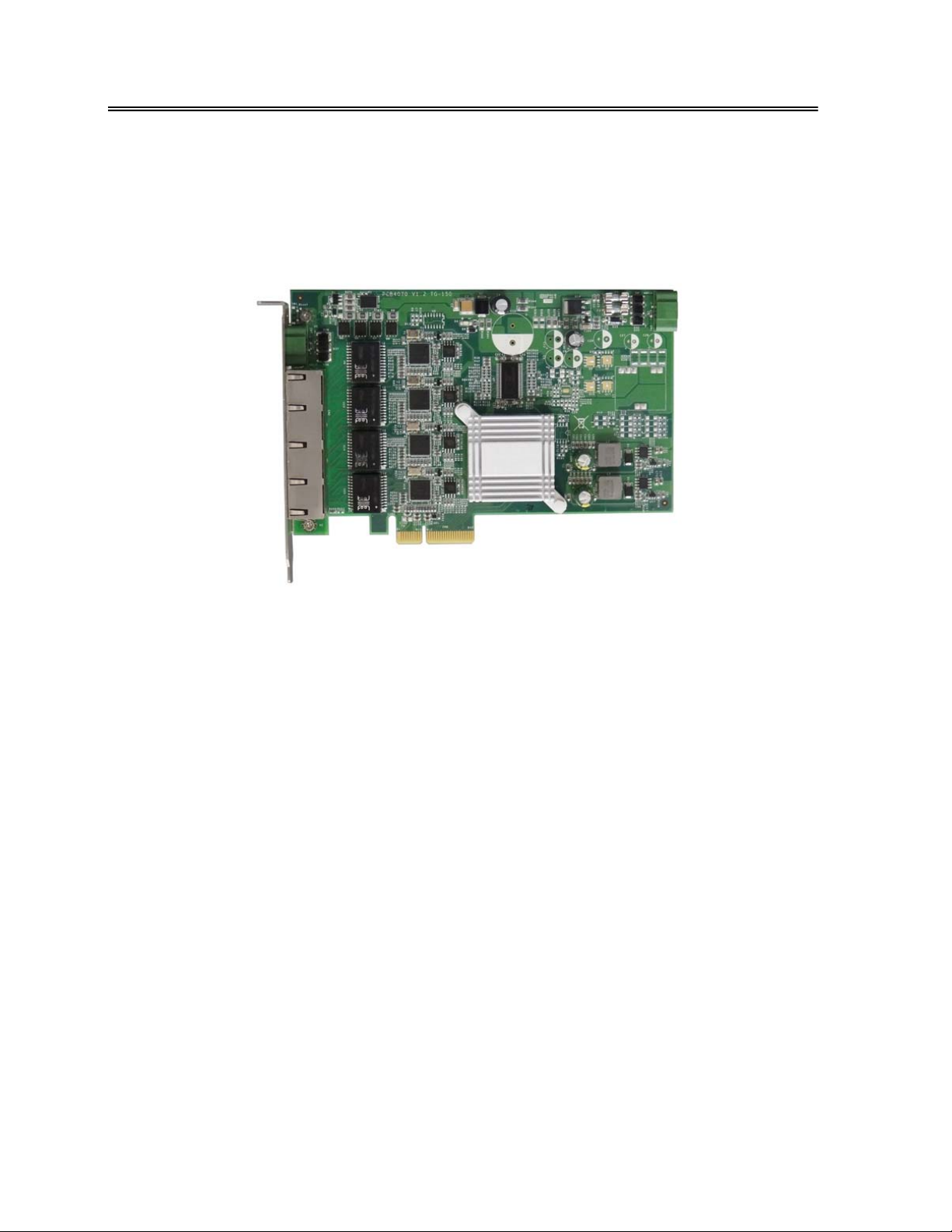
The FB4070 is x4 PCIe/PoE Giga LAN card with support for four PoE ports independent
Intel® i210AT Gigabit Ethernet.
The FB4070 supports IEEE802.3af/at Power over Ethernet (PoE) Power Sourcing
Equipment (PSE) and can detect an IEEE802.3af/at compliant Powered D evice (PD).
Using external 48V to 55V DC power inputs through Terminal Block, data and power
can be trans m itted to a Pow ered Device (PD) over the same twiste d - p a ir Ethern e t
cable through LAN port. It provides auto-detection to ensure compatibility with both
PoE and conventional non-PoE devices, the PoE (Power over Ethernet) is a technology
to supply electrical power along with data on a standard Ethernet cable. And the
each port can delivers 15.4 W or 25.5 W of power and 1000 Mb/s bandwidth over a
CAT-5(e)/ CAT-6 cable of up to 100 meters.
The FB4070 features supports 9 KB jumbo frame, link aggregation (LAG), which conduct
exceptional throughout performance for receiver large data.
The FB4070 PoE LAN card is perfect for multi LAN, powering IP telephones, wireless LAN
access points, webcams, Ethernet hubs and switches and many more devices.
1
Page 5

FabiaTech Corporation
Series Comparison Table
Model FB4070
LAN Chipset Intel ® i210
RJ45 LAN port
(100/1000Mbps)
Jumbo Frame 9KB
Link Aggregation (LAG)
PoE Capability *
Cable Requirement CAT 5(e) or CAT 6
PCIe BUS Interface x4 PCI Express
Operating Temperature 0~+ 55℃ (32~131℉) With Air Flow
Storage Temperature -20~+85℃(-4~185℉)
Dimensions (Unit: mm) 167.7(D) x 107.7(W)
IEEE 802.3af Compliant
Each port up to 15.4W
IEEE 802.3at Compliant
Each Port up to 25.5W
Four
Yes
100 Meters Max.
* The PoE DC power supply from external DC Power Unit. ( Optional )
2
Page 6
FabiaTech Corporation
Layout
3
Page 7

FabiaTech Corporation
Specifications
PCI Express® x4 compliant
Four Intel® i210 Gigabit Ethernet Mac Controller and PHY ports
¾ Support 9KB Jumbo Frame and Link Aggregation (Teaming)
¾ Supports IEEE 802.1 Audio Video Bridging (AVB)
¾ Supports IEEE 802.3u Auto-Negotiation
¾ Support IEEE 1588 compliant
Supports PoE (Power over Ethernet) IEEE 802.3 af/at compliant
¾ Powered Device (PD) auto detection and classification
¾ Supports Inrush current, current limit, and short-circuit protection
LED indicator –RJ45
¾ LAN Data access
¾ PoE Powered Device (PD) connectivity status
Power requires
¾ Base on FB4070:+3.3V/2.4A, +12V/220mA Max.
¾ PoE Power Input: 48V/1.6A Max. (Power consumption: 75W Max.)
¾ PoE Power Input: 48V/2.5A Max. (Power consump tion: 120W Max.)
48VDC Terminal Block power input for 15.4W or 25.5W per PoE port
EMI Considered on every output signals.
Compact size, 167.7 mm x 107.7 mm.
4
Page 8

FabiaTech Corporation
Packing List
Upon receiving the package, verify the following things. Should any of the mentioned
happens, contact us for immediate service.
• Unpack and inspect the FB4070 package for possible damage that may occur
during the delivery process.
• Verify the accessories in the package according to the packing list and see if
there is anything missing or incorrect package is included.
• If the cable(s) you use to install the FB4070 is not supplied from us, please make
sure the specification of the cable(s) is compatible with the FB4070 system
board.
Note: after you install the FB4070, it is recommended that you keep the diskette or
CD that contains drivers and document files, document copies, and
unused cables in the cartoon for future use.
The following lists the accessories that may be included in your FB4070 package.
Some accessories are optional items that are only shipped upon order.
• One FB4070x PCIe/PoE Giga LAN card with anti-Static bag.
• One 2-pin apartable terminal block for DC Power-In.
• One compact disc containing manual file in PDF format and necessary
drivers and utilities
Optional:
• One AC100~240VAC-48VDC/1.6A 75W Power Supply. (P/N: 1601210010R)
• One AC100~240VAC-48VDC/3.3A 150W Power Supply. (P/N: 1601210009R)
5
Page 9

FabiaTech Corporation
6
Page 10

FabiaTech Corporation
Chapter 2 Hardware Installation
This chapter introduces the board connectors, jumper settings and then guides you to
apply them for field application.
Before Installation
Before you install the system board, make sure you follow the following descriptions.
1. Before re moving the board from its anti-static bag, wear an anti-static strap to
prevent the generation of Electricity Static Discharge (ESD). The ESD may be
created from human body that touches the board. It may do damage to the
FB4070 board circuit.
2. Install or unplug the FB4070 card, be sure that the power is disconnected from the
system. If not, this may damage the system board components, module, or the
FB4070 card.
3. The FB4070 can be installed in a PCI Express x4, x8, or x16 slot. And please make
sure that there PCI Express slot available on your system board. Before you install
the board, be careful with the pin orientations.
7
Page 11

FabiaTech Corporation
Hardware Features
The following lists the connectors and jumpers to install the FB4070.
Item Description
CN1 Internal PoE power connector with 2-pin DC-In terminal block
CN2 4 LAN Ports and LED’s status with RJ45 Connect or
CN7 External PoE power connector with 2-pin DC-In terminal block
8
Page 12
FabiaTech Corporation
CN2: 4 LAN Ports RJ45 Connector
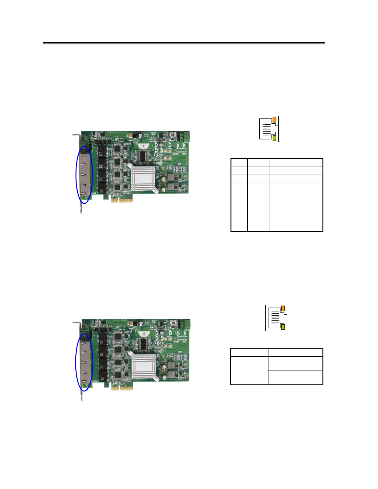
The CN2 -RJ45 has 4 PoE LAN ports, each of which has 2 LED’s indicators. The upside
LED (orange) indicates LAN port accessing data. The downside LED (green) indicates
PSE power status on while Power Device (PD) is hooked. The following lists the pin
assignment with RJ45 of CN2.
RJ45
(Fron t V iew)
8
1
¾
CN2: PoE LAN LED Power Status
RJ45 10/100 Giga PoE
TPTX+ MDI0+ DC_48V
1
TPTX - MDI0- DC_48V
2
TPRX+ MDI1+ DC_0V
3
FBG1 MDI2+ DC_48V
4
5 FBG1
6 TPRX 7 FBG2
8 FBG2
MDI2- DC_48V
MDI1- DC_0V
MDI3+ DC_0V
MDI3- DC_0V
The FB4070 provides green LED to indicate operating conditions of the PoE LAN
ports. The green LED is on while connect to Powered Device (PD) and it is off when
the Powered Device (PD) is removed. The table below is to illustrate PoE LED status.
LED Status
Green
RJ45
8
1
(Fron t V iew)
Light_On
PoE On
Light_Off
PoE Off
9
Page 13
FabiaTech Corporation
CN1 & CN7: DC-In Terminal Block Connector
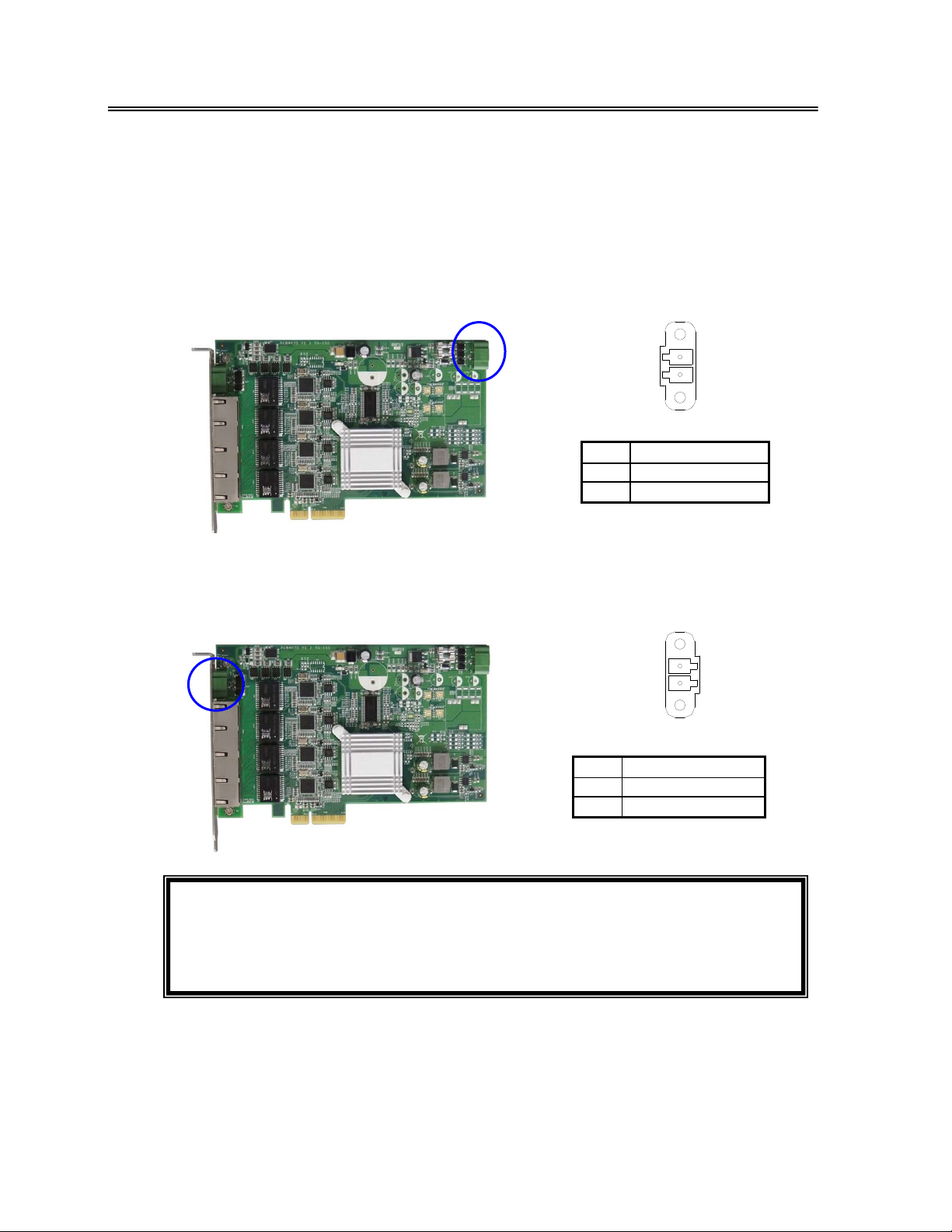
The PoE power source comes from either the CN1 or CN7, DC-in terminal block
connecto rs, both of which a re connected to external po wer source 48~55 VDC input.
connecto rs, both of which a re connected to external po wer source 48~55 VDC input.
Use external 2-pin apartable terminal block to connect CN1 or CN7. See following
Use external 2-pin apartable terminal block to connect CN1 or CN7. See following
figure and a side pictures.
figure and a side pictures.
¾ CN1: DC-in Terminal Block Connector ¾ CN1: DC-in Terminal Block Connector
al block
+
-
DC IN
48V~55V
Terminal Block
PinPin
+ DC_IN_+48V
- Ground
Description
¾ CN7: DC-in Terminal Block Connector ¾ CN7: DC-in Terminal Block Connector
DC IN
48V~55V
-
+
Terminal Block
Pin
+ DC_IN_+48V
- Ground
: 1. Ensure the correct voltage and correct the positive (+) and the GND (-)
Note
Description
before connecting CN1 or CN7 DC-In terminal block.
2. The PoE end de vice ( Lik e Acc ess p oin t, IP came ra, IP P hon e, and othe r
device) need conforming to PoE Specification.
10
Page 14
FabiaTech Corporation
Install FB4070 PCIe PoE/LAN card to System- Host Computer
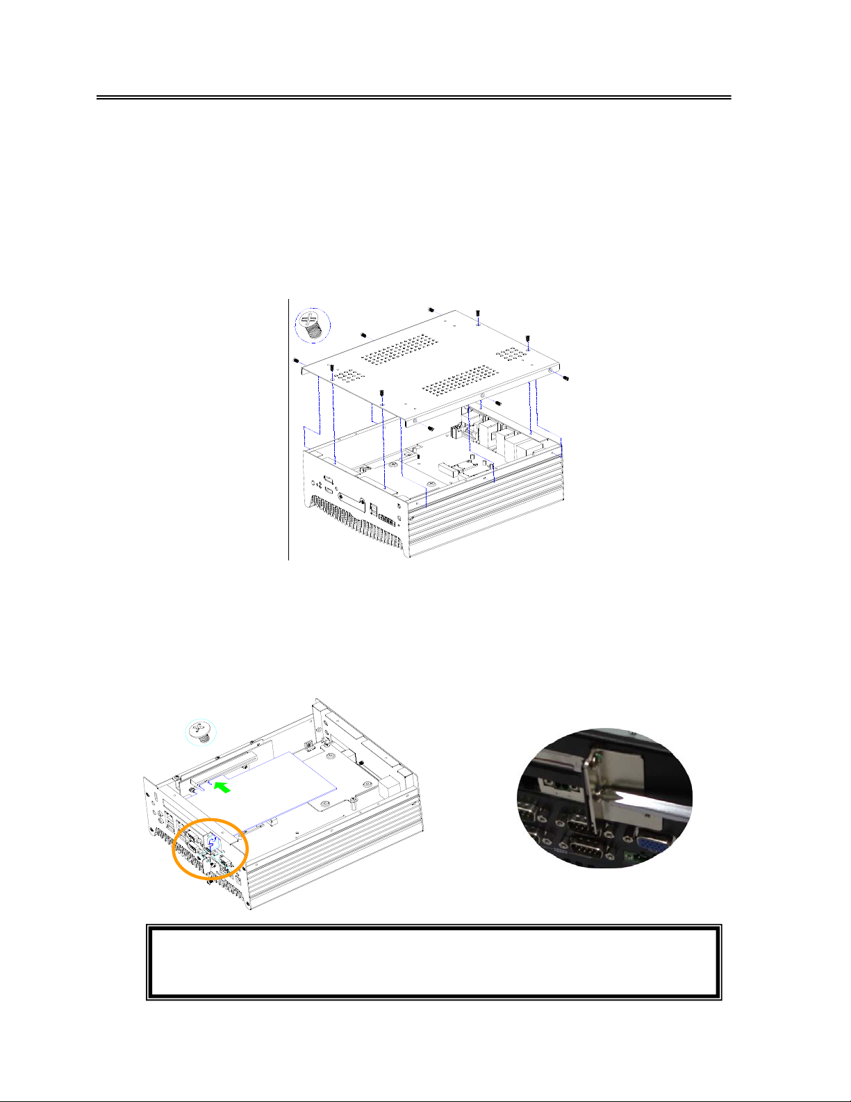
If installing the FB4070, can remove the chassis cover of host computer then insert to
x4 PCI Express slot (Or x8, x16 slot). Below example: Install FB4070 PCIe PoE LAN card
to FX5637S1 system. (Please see the spots circled.)
¾ a. Unscrew Bottom cover
Use a cross-head screwdriver to remove ten screws that secure the bottom cover.
¾ b. Installing FB4070 PCIe PoE LAN card
The following figure will guide you how to install FB4070 card and screw the L-Type
Metal on the PCIE card Bracket and expansion card holder. See following figures.
b1. To installing Expansion Card – PCI/PCIE Card
D
R
A
C
h
t
g
)
n
h
e
l
c
_
n
f
i
l
6
a
.
h
6
(
s
s
F
e
E
r
p
R
x
E
m
I
m
8
C
6
P
1
: 1. The FB4070 need the +12V/250mA and +3.3V/1.1A from PCIE Bus.
Note
2. The FX5637S1 PCIE bus supports x1/x2/x4 lanes via PCIE x16 slot.
11
Page 15
FabiaTech Corporation
b2. Installing FX5637K2 Kit (Optional) - Expansion card holder
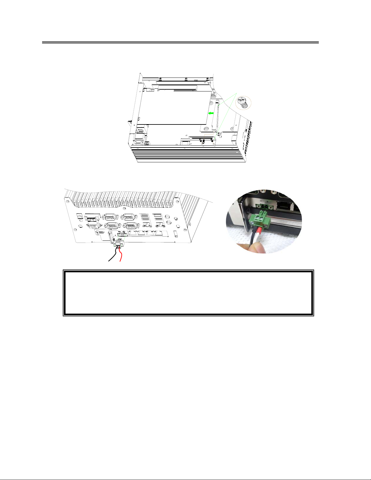
¾ c. Connector External VDC Power Supply to CN7 of FB4070
FX5637K2 (OPTION )
: 1. The PoE of PD needs using the CN1 or CN7 to connect with external
Note
power supply DC-IN +48V ~55V input (+48V/2.4A Max).
2. When inserting LAN cable of the Powered Device (PD) to CN2 (RJ45),
the indicator of the green LED status will be on.
12
Page 16
FabiaTech Corporation
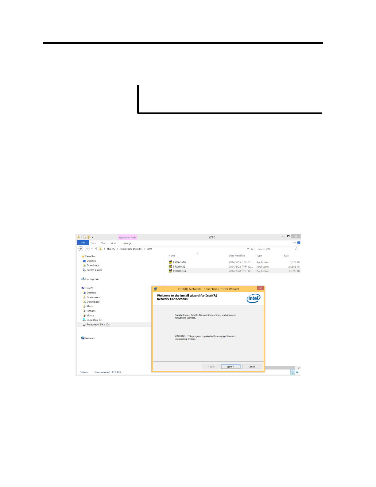
Chapter 3 Software Installation and Setting Chapter 3 Software Installation and Setting
The enclosed CD diskette includes FB4070 LA N driver. To install driver and configure
The enclosed CD diskette includes FB4070 LA N driver. To install driver and configure
setup you FB4070 card, you need to perform the following steps.
setup you FB4070 card, you need to perform the following steps.
LAN Driver (Intel I210AT) LAN Driver (Intel I210AT)
WIN7WIN7/8/8.1 Server 2008 R2/2012 R2 X86/X64 Driver /8/8.1 Server 2008 R2/2012 R2 X86/X64 Driver
Step 1: Step 1: To install the LAN driver, insert the DVD ROM into the CD ROM device, and
To install the LAN driver, insert the DVD ROM into the CD ROM device, and
enter DRIVER>LAN>I210AT.
enter DRIVER>LAN>I210AT.
Step 2: Step 2: Execute PROWin32.exe file or PROWinx64.exe. Execute PROWin32.exe file or PROWinx64.exe.
13
Page 17
FabiaTech Corporation
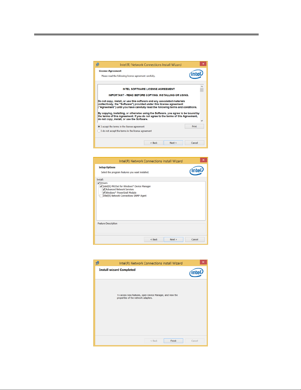
Step 3: Click “Next “to License Agreement. (Need select “I accept the teams in
the license agreement”.)
Step 4: Click “Next” to continue installation.
Step 4: Click “Finish” to Install wizard completed!
14
Page 18
FabiaTech Corporation
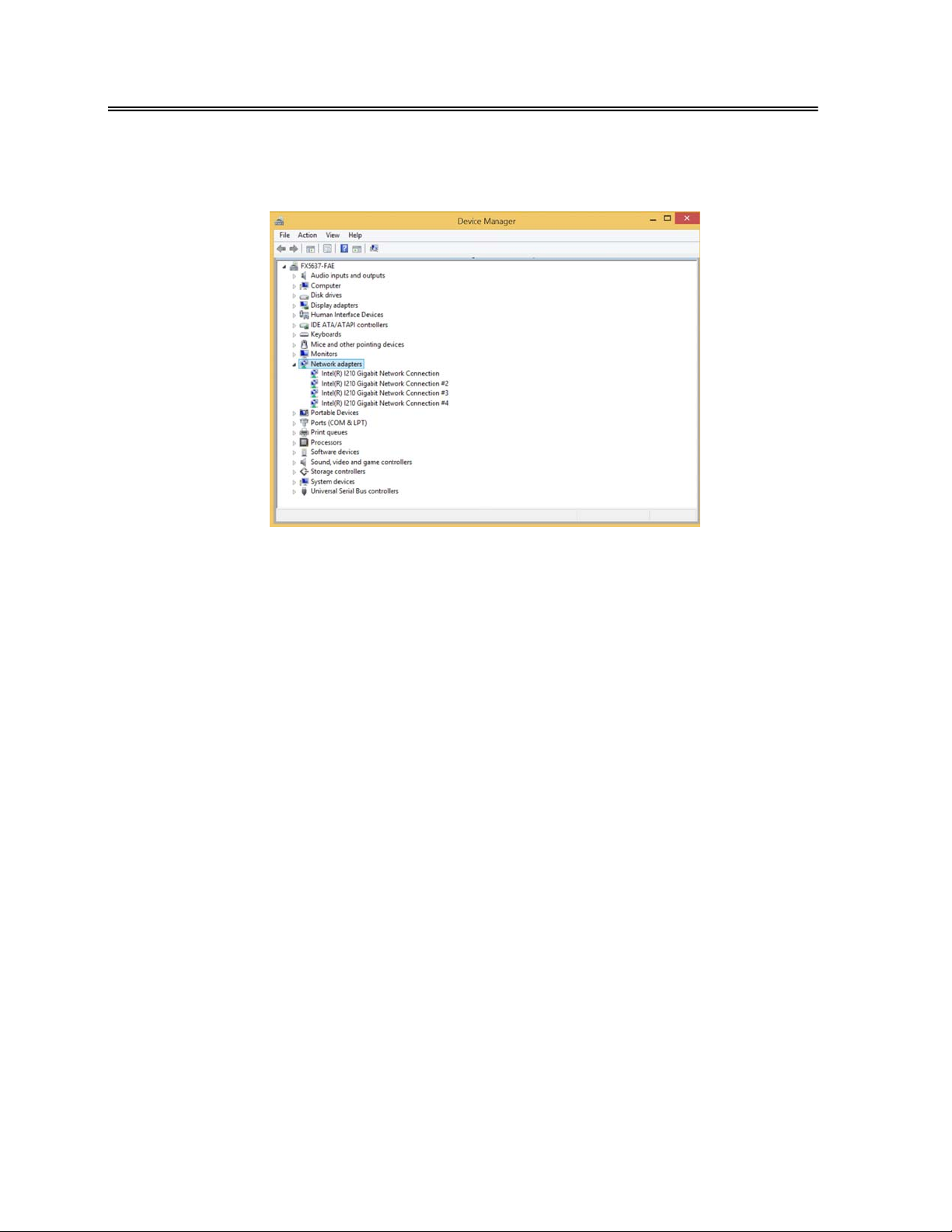
Step 5: You will see the 4 Intel ® i210 Gigabit Network Connection LAN device
completed show the Device Manager!
15
Page 19
FabiaTech Corporation
LAN Driver Configuration Setting
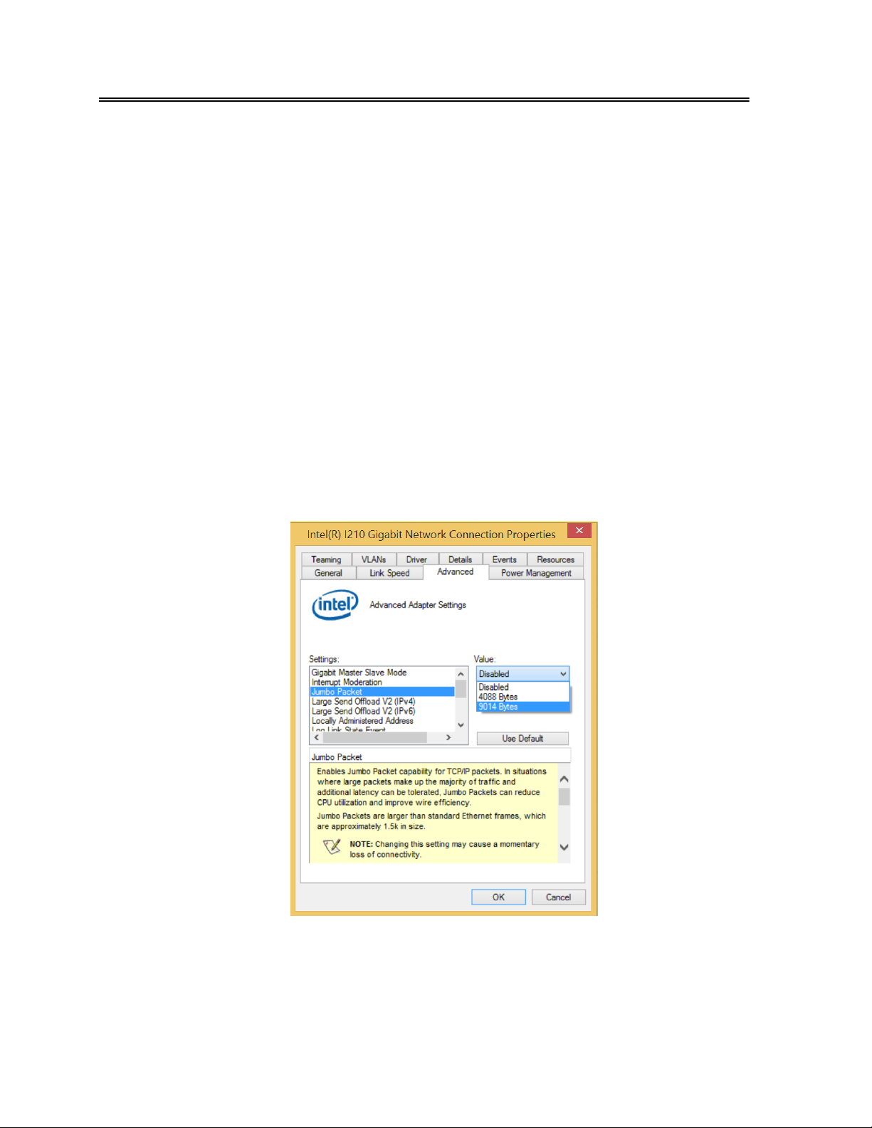
The LAN configuration setting with scroll down to and double-click the "Network
adapters" header in the Device Manager list. Right-click the Intel ® i 210 Gigabit
Network Connection and click "Properties" on the context menu. The context menu
settings listed in the "Advanced" tab enable you to customize how the adapter
handles Receiver Buffers, Transmit Buffers, Jumbo Packet, and other capabilities. When
connecting to a high-speed PoE or Non-PoE device, that’s can settings of drivers can
get the better performance.
Advanced Setting Driver
Click the "Advanced" tab in the Intel ® i210 Gigabit Network Connec tion Proper ties
window, in this section, we’ll discuss these settings. You can refer to the information to
fine tune your system.
¾ Jumbo Packet
Jumbo Frames can increase throughput and decrease CPU utilization by putting more
data in each frame, thereby sending out fewer frames. The standard ether- net frame
size is 1514 bytes, while Jumbo Frames can contain 4088, or 9014 bytes.
16
Page 20
FabiaTech Corporation
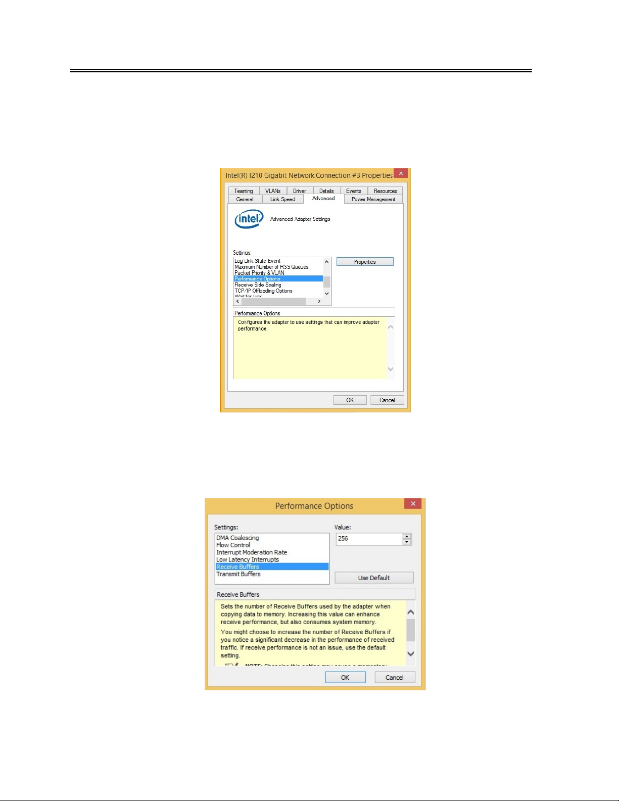
¾ Performance Options
Receive Buffers and Transmit Buffers are sets the number of Buffers used by the
adapter when copying data to memory. Increasing this value can enhance receive
performance, but consumes system memory.
Receive Buffers
You might choose to increase the number of Receive Buffers if you notice a significant
decrease in the performance of received traffic. If receive performance is not an issue,
use the default setting.
17
Page 21
FabiaTech Corporation
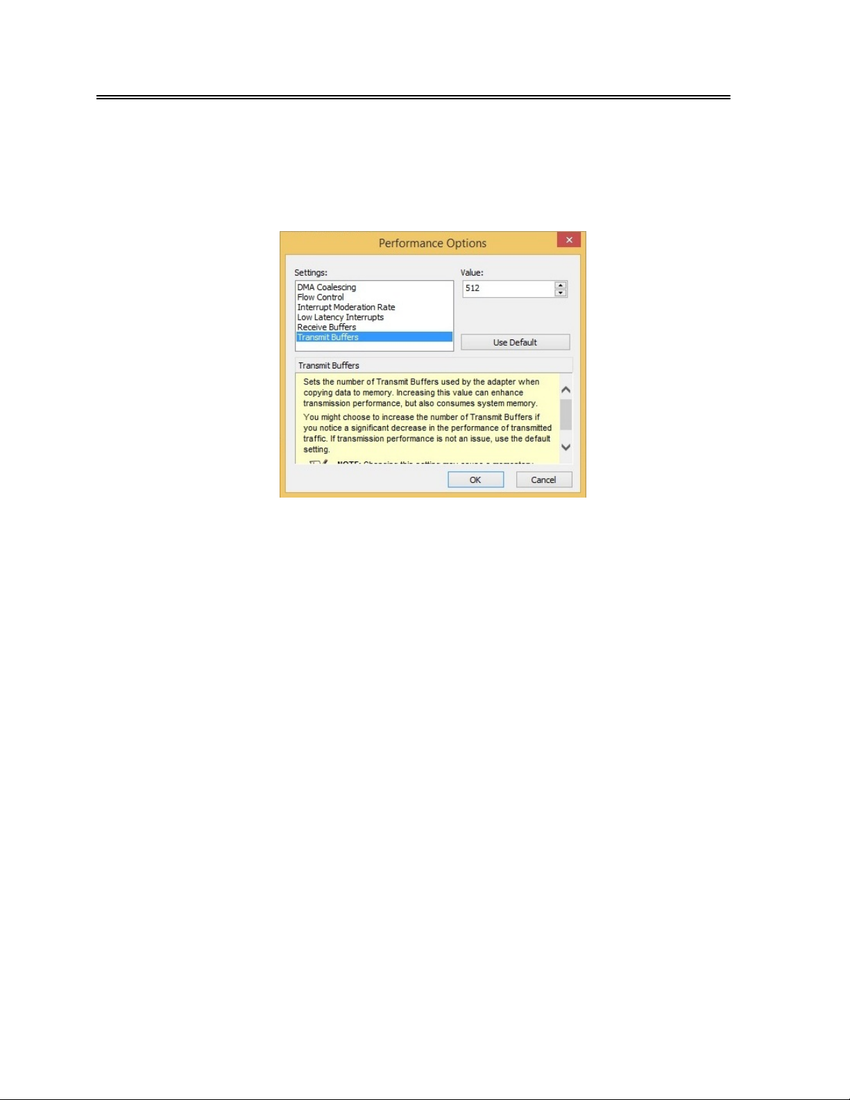
Transmit Buffers
You might choose to increase the number of Transmit Buffers if you notice a significant
decrease in the performance of transmit traffic. If transmit performance is not an issue,
use the default setting.
18
Page 22

FabiaTech Corporation
Chapter 4 Technical Reference
This section provider description the hardware that may occur when you
operate the system, and also gives you the suggestions on solving the
problems.
Topic include:
z Technical Reference
z FB4070 Dimension
Technical Reference
Physical and Environmental
Temperature: Operating 0°C ~ 60°C
Relative humidity 5 % to 95 % non-condensing
For PoE input Power Supply:
Input AC Voltage Range: 115V/2A ~ 230V/1.2A, 50Hz ~60Hz
Output DC Voltage: 48V/1.6A/75W for IEEE 802.3 af
48V/3.3A/150W for IEEE 802.3 at
19
Page 23
FabiaTech Corporation
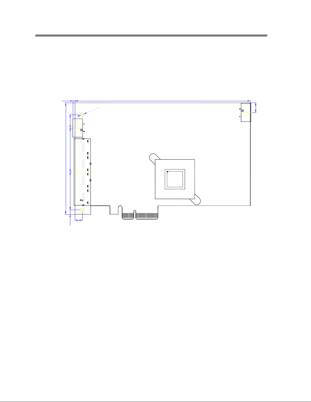
Dimension
Appendix
2.1
167.7
5
.
3
O
8
.
2
1
48Vin
1
.
2
4
7
.
6
0
1
1
.
6
3
6.9
4
.
4
48Vin
3
.
9
20
 Loading...