

Page 1
- Libretto di Istruzioni
- Instructions Manual
- Manual de instrucciones
Page 2

Page 3
INDICE
STEAM OFF SYSTEM........................................................................................................................................................... 3
CONSIGLI E SU
CARATTERI
INSTALLAZ
USO ..............................................................................................................................
MANUTENZIONE ................................................................................................................................................................ 14
GGERIMENTI.............................................................................................................................................. 4
STICHE.............................................................................................................................................................. 7
IONE .................................................................................................................................................................. 8
........................................................ 1 2
IT
INDEX
STEAM OFF SYSTEM......................................................................................................................................................... 15
RECOMMENDATIONS AND SUGGESTIONS ................................................................................................................... 16
CHARACTERISTICS ........................................................................................................................................................... 19
INSTALLAT
USE ...............................................................
MAINTENANCE ..............................................................................................................................
ION.................................................................................................................................................................... 20
....................................................................................................................... 24
..................................... 26
INDICE
STEAM OFF SYSTEM..........................................................................................................................................................27
CONSEJOS Y SUGERENCIAS........................................................................................................................................... 28
CARACTERÍSTICAS ........................................................................................................................................................... 31
INSTALACIÓN ..................................................................................................................................................................... 32
USO...................................................................................................................................................................................... 36
MANTENIMIENTO ............................................................................................................................................................... 38
SCHEMA ELETTRICO - ELECTRIC DIAGRAM - ESQUEMA ELéCTRICO..................................................................... 39
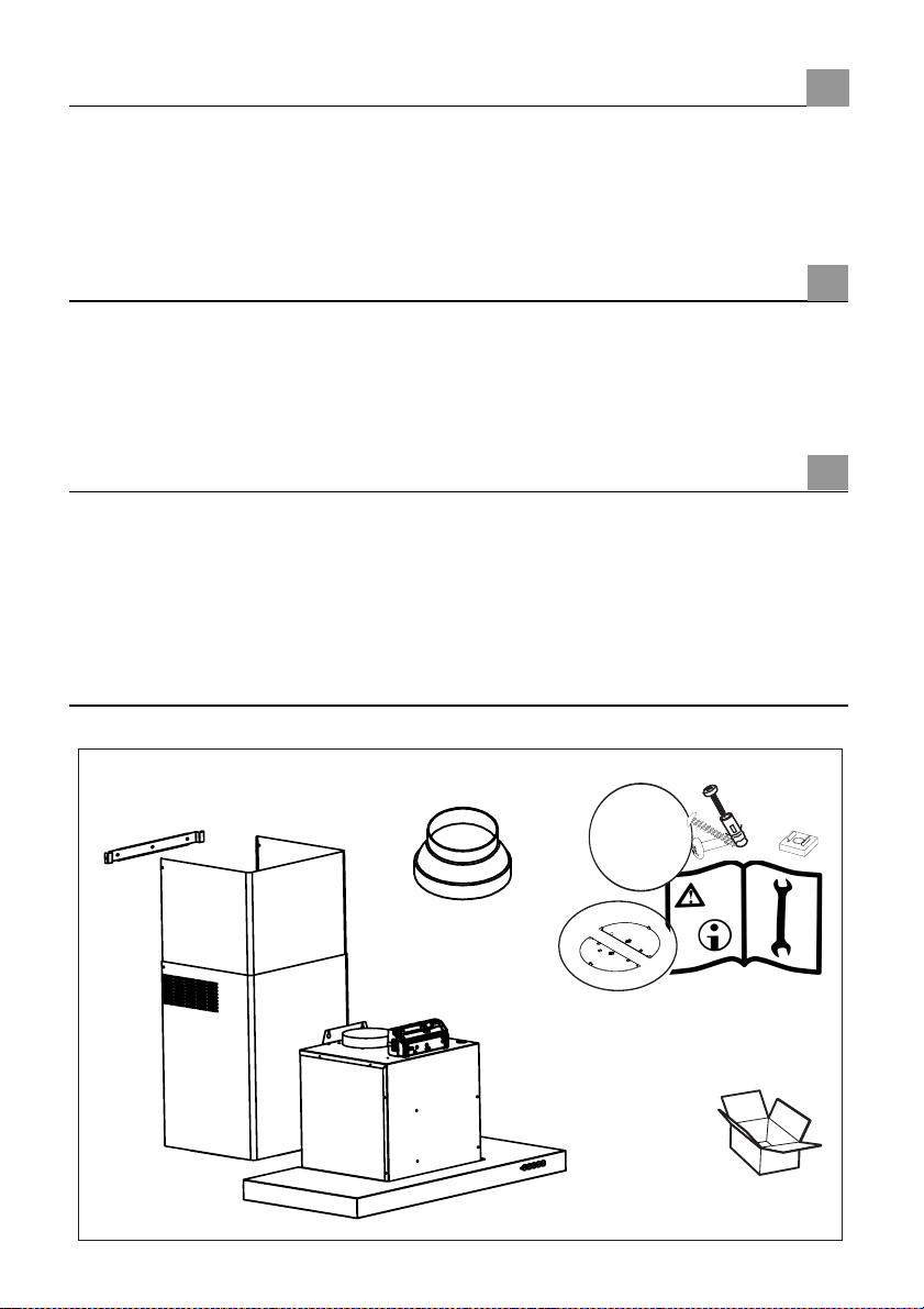
7x(Ø5x40)
2x(Ø4x6)
4x(M4x10)
EN
ES
4x
± 25Kg
Page 4
STEAM OFF SYSTEM
STEAM OFF
COMFORT ESCLUSIVO
SENZA CONDENSA
•
Nei piani a induzione, il differenziale termico che si crea tra la parte calda
adiacente alla cottura e l’aria più fredda sotto la parte aspirante della
cappa provoca un effetto condensa e gocciolamento che fino ad oggi
nessuno era riuscito a risolvere. La dispersione del vapore tende inoltre a
coinvolgere l’ambiente
ante e basi dei pensili. Con Steam Off System tutto questo viene
eliminato.
circostante e la parte strutturale della cucina come
SYSTEM
UNA CAPPA
CHE “RESPIRA”
•
Getti di aria controllata rilasciati in forma elicoida-le e a geometria variabile
creano due
Steam Off System quindi la cappa non solo aspira ma emette anche dei
getti d’aria che creano una vorticosità ed accelerazione e favoriscono il
convogliamento e la captazione del vapore.
Finita la condensa ed il suo deposito sotto e intorno alla cappa!
IT
vortici grazie ai quali si controlla la salita di fumi e vapore. Con
3
3
Page 5
CONSIGLI E SUGGERIMENTI
Le Istruzioni per l’uso si riferiscono ai diversi modelli di questo
apparecchio. Pertanto, si potrebbero trovare descrizioni di singole
caratteristiche che non appartengono al proprio apparecchio specifico.
INSTALLAZIONE
• Il fabbricante non potrà ritenersi responsabile per eventuali danni risultanti
da un’installazione o utilizzazione impropria.
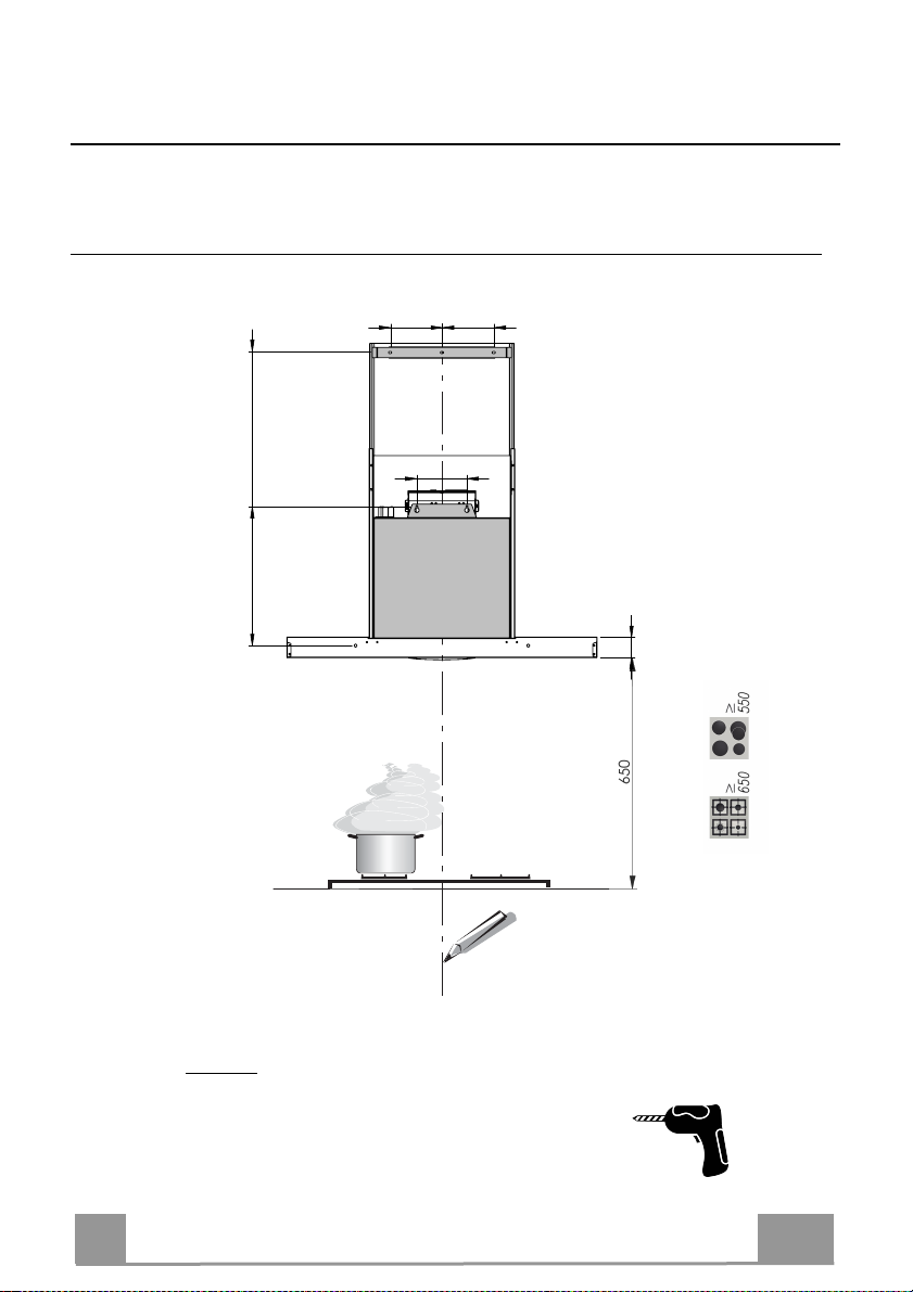
• La distanza minima di sicurezza tra il piano cottura
e la cappa aspirante è di 650 mm (alcuni modelli
possono essere installati a un’altezza inferiore;
vedere il paragrafo relativo alle dimensioni di lavoro
e all'installazione).
• Controllare che la tensione di rete corrisponda a
quella indicata sulla targa dati applicata all’interno
della cappa.
• Per gli apparecchi di Classe I, controllare che la rete di alimentazione
domestica disponga di un adeguato collegamento a massa.
Collegare l'aspiratore al condotto dei fumi mediante un tubo con diametro
minimo di 120 mm. Il percorso dei fumi deve essere il più corto possibile.
• Non collegare la cappa aspirante ai condotti fumari che trasportano fumi di
combustione (per es. caldaie, camini ecc.).
• Se l’aspiratore è utilizzato in combinazione con
apparecchi non elettrici (per es. apparecchi a gas),
deve essere garantito un sufficiente grado di
aerazione nel locale per impedire il ritorno di flusso
dei gas di scarico. La cucina deve avere un'apertura
comunicante direttamente con l'esterno per garantire
l'afflusso di aria pulita. Quando la cappa per cucina è utilizzata in
combinazione con apparecchi non alimentati dalla corrente elettrica, la
pressione negativa nel locale non deve superare 0,04 mbar per evitare che i
fumi vengano riaspirati nel locale dalla cappa.
• In caso di danneggiamento del cavo di alimentazione, occorre farlo sostituire
dal produttore o dal reparto di assistenza tecnica per evitare qualsiasi
rischio.
2°
IT
4
Page 6
• Se le istruzioni di installazione del piano cottura a gas specificano una
distanza maggiore di quella sopra indicata, è necessario tenerne conto.
Devono essere rispettate tutte le normative riguardanti lo scarico dell'aria.
• Usare solo viti e minuteria di tipo idoneo per la cappa.
Avvertenza: la mancata installazione delle viti o dei dispositivi di fissaggio in
conformità alle presenti istruzioni può comportare rischi di scosse elettriche.
• Collegare la cappa all'alimentazione di rete mediante un interruttore bipolare
con distanza tra i contatti di almeno 3 mm.
USO
• La cappa aspirante è progettata esclusivamente per l’uso domestico allo
scopo di eliminare gli odori dalla cucina.
• Non usare mai la cappa per scopi diversi da quelli per cui è stata progettata.
• Non lasciare mai fiamme alte sotto la cappa quando è in funzione.
• Regolare l'intensità della fiamma in modo da dirigerla esclusivamente verso
il fondo del recipiente di cottura, assicurandosi che non ne avvolga i lati.
• Le friggitrici devono essere costantemente
controllate durante l’uso: l’olio surriscaldato
potrebbe incendiarsi.
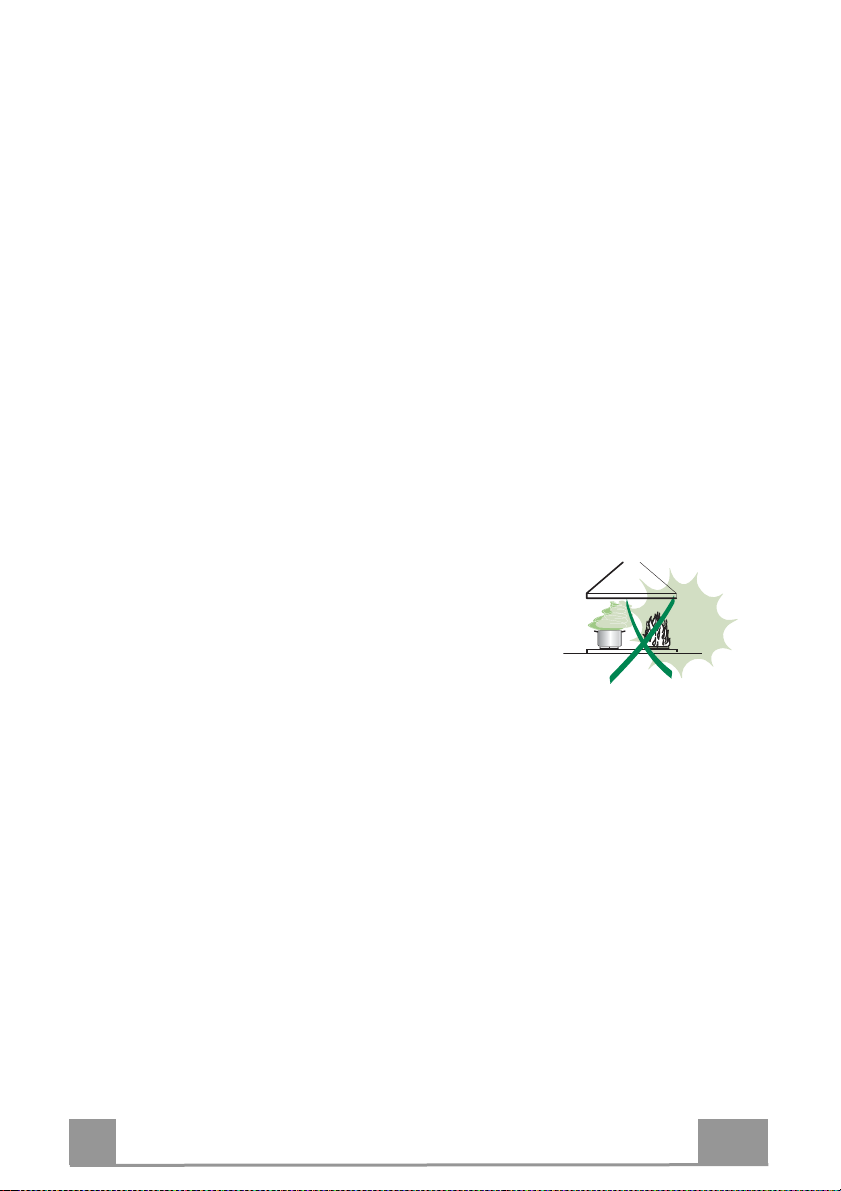
• Non cuocere al flambé sotto la cappa: si potrebbe
sviluppare un incendio.
• Questo apparecchio può essere utilizzato da
bambini di età non inferiore a 8 anni e da persone con ridotte capacità psicofisico-sensoriali o con esperienza e conoscenze insufficienti, purché
attentamente sorvegliati e istruiti su come utilizzare in modo sicuro
l'apparecchio e sui pericoli che ciò comporta. Assicurarsi che i bambini non
giochino con l'apparecchio. Pulizia e manutenzione da parte dell'utente non
devono essere effettuate da bambini, a meno che non siano sorvegliati.
IT
5
Page 7

• “ ATTENZIONE: le parti accessibili possono diventare molto calde durante
l’uso degli apparecchi di cottura ”.
MANUTENZIONE
• Spegnere o scollegare l’apparecchio dalla rete di alimentazione prima di
qualunque operazione di pulizia o manutenzione.
• Pulire e/o sostituire i filtri dopo il periodo di tempo specificato (pericolo di
incendio).
• I filtri antigrasso devono essere puliti ogni 2 mesi di funzionamento o più
frequentemente in caso di utilizzo molto intenso e possono essere lavati in
lavastoviglie.
• Il filtro al carbone attivo non è lavabile né è rigenerabile e deve essere
sostituito ogni 4 mesi di funzionamento circa o più frequentemente in caso di
utilizzo molto intenso.
• "Vi è il rischio di incendio se la pulizia non viene effettuata secondo le
istruzioni".
• Pulire la cappa utilizzando un panno umido e un detergente liquido neutro.
Il simbolo sul prodotto o sulla sua confezione indica che il prodotto non
può essere smaltito come un normale rifiuto domestico. Il prodotto da smaltire
deve essere conferito presso un apposito centro di raccolta per il riciclaggio
dei componenti elettrici ed elettronici. Assicurandosi che questo prodotto sia
smaltito correttamente, si contribuirà a prevenire potenziali conseguenze
negative per l’ambiente e per la salute che potrebbero altrimenti derivare dal
suo smaltimento inadeguato. Per informazioni più dettagliate sul riciclaggio di
questo prodotto, contattare il Comune, il servizio locale di smaltimento rifiuti
oppure il negozio dove è stato acquistato il prodotto.
IT
6
Page 8
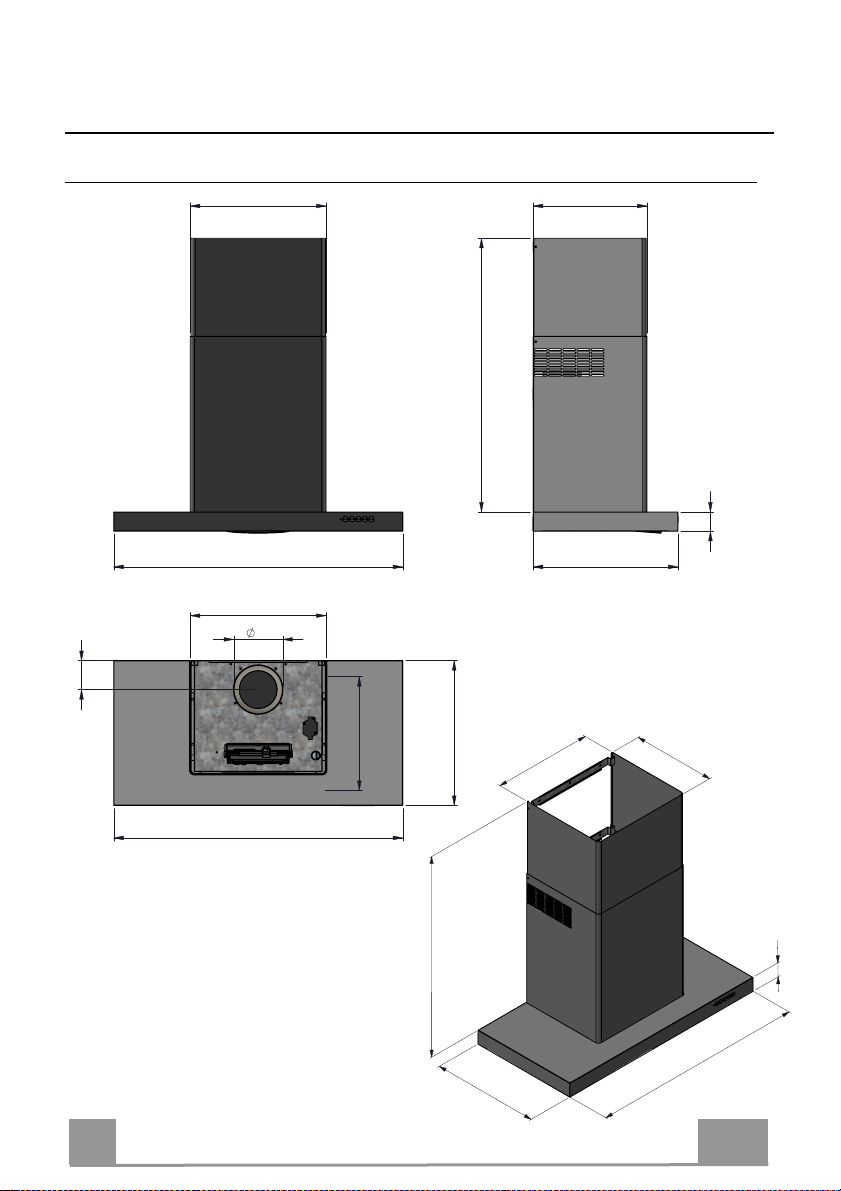
CARATTERISTICHE
422
Ingombro
354
MIN.545 - MAX.850
60
90
600-900-1200
422
150
600-900-1200
354
450
422
MIN.545 - MAX.850
450
450
354
60
600-900-1200
IT
7
Page 9
INSTALLAZIONE
MIN165-MAX448
403
Foratura Parete e Fissaggio Staffe
150 150
III
BI-B
145
II
AI-A
II
CI-C
60
IT
LEGGERE le istruzioni prima di adoperarsi al montaggio
I.
II.
Disegnare sulla parete i 7 punti indicati e forare:
AI-AII : Fori per fissaggio box motore
o
o
o
III
BI-B
: Fori per fissaggio staffa del tubo
CI-CII : Fori per fissaggio di sicurezza
!
8
Page 10
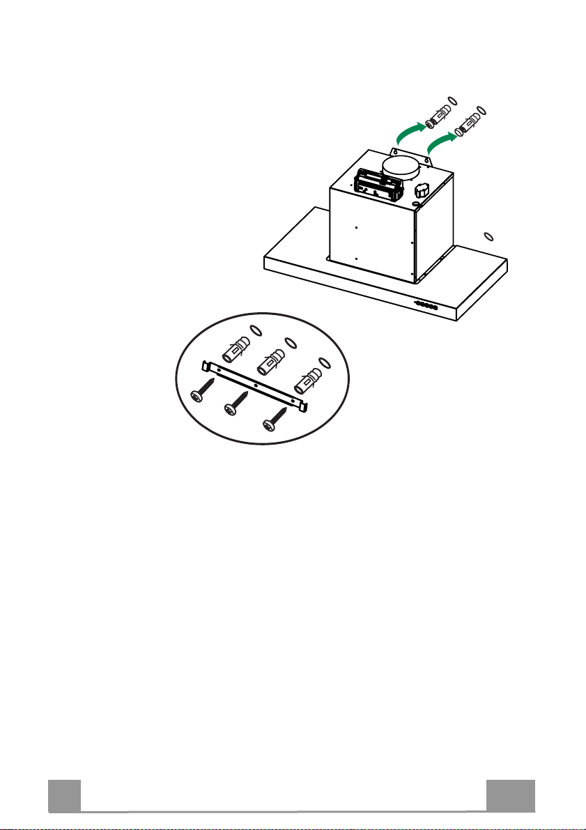
Inserire le viti 2x (Ø5x40)
III.
nei tasselli in AI-AII senza stringere;
agganciare gli occhielli del corpo cappa
e stringere nei punti A'-A''
Fissare la staffa dei tubi
IV.
con le viti 3x (Ø5x40) in
posizione BI-B
III
I
A
II
A
II
C
I
B
II
B
III
B
E' possibile un fissaggio di sicurezza agendo
V.
sui fori C'-C'' e avvitando 2x (Ø5x40) dall'interno
della cappa, dopo aver rimosso i filtri antigrasso.
IT
9
Page 11
Connessioni
USCITA ARIA VERSIONE ASPIRANTE
Per installazione in Versione Aspirante co
tubazione di uscita per mezzo di un tubo rigido o flessibile di
ø150 o 120 mm, la cui scelta è lasciata all'installatore.
Per collegamento con tubo ø120 mm, inserire la Flangia di
•
ri
duzione sull’Uscita del Corpo Cappa.
Fissare
•
•
il tubo con adeguate fascette st
materiale occorrente non è in dotazione.
Togliere eventuali Filtri Antiodore al
Collegare la Flangia X di riduzione alla bocca del motore
•
• Fissare il Raccordo T nel tubo inferiore utilizzando 4 viti (4.2x6.5)
Procedere con il fissaggio dei tubi al corpo cappa
Assicurarsi della presenza del Filtro Antiodore al Carbone attivo.
•
llegare la Cappa alla
ringitubo. Il
Carbone attivo.
USCITA ARIA VERSIONE FILTRANTE
ø 120ø 150
IT
T
X
10
Page 12
CONNESSIONE ELETTRICA
La tensione di rete deve corrispondere alla tensione riportata
•
sull’etichetta caratteristiche situata all’interno della cappa. Se
provvista di spina, allacciare la cappa ad una presa conforme
alle norme vigenti posta in zona accessibile. Se sprovvista di
spina (collegamento diretto alla rete), o la spina non è posta in
zona accessibile, applicare un interruttore bipolare a norma che
assicuri la disconnessione completa della rete nelle condizioni
della categoria di sovratensione III, conformemente alle regole
di installazione.
Sostituzione Led
!
Per la sostituzione contattare l’Assistenza Tecnica.
Montaggio Camino
Inserire la coppia di tubi fino ad aderire al motore
•
Camino superiore
Fissare lateralmente alla Staffa con le viti in dotazione
•
2x (Ø4x6)
Camino inferiore
può essere fissato utilizzando le 4asole poste alla base
•
del tubo inferiore. In esse va incastrato il dado in gabbia
4x ( ) [vedi A]. Poi, dopo aver tolto i filtri,
si serra con le viti 4x (M4x10) dal fondo della cappa
A
A
IT
11
Page 13
USO
Quadro comandi
Accende/Spegne il motore alla prima velocità, il led del tasto si accende, e rimane
acceso a tutte le velocità motore.
Premuto brevemente accende il motore, se premuto da qualsiasi velocità spegne il
motore.
quando tutti i carichi sono spenti (Motore e luci OFF), in caso di allarme filtri CA
•
o Grassi attivo, si effettua il reset dei medesimi tenendo il tasto premuto per
circa 2 sec. visualizzando il triplo lampeggio di tutti i led.
Accende il motore alla velocità 2, il led del tasto si accende solo alla vel. 2.
• Tenendo il tasto premuto per circa 2 sec., quando tutti i carichi sono spenti
(Motore e luci OFF), si attiva l’allarme Filtri Carbone esauriti visualizzando un doppio
lampeggio del led relativo al tasto 1 . Per disattivare l’allarme Filtri Carbone
esauriti, si preme di nuovo il tasto per altri 2 sec. visualizzando un singolo lampeggio
del led relativo al tasto 1.
Accende il motore alla velocità 3, il led del tasto si accende solo alla vel. 3.
• Tenendo premuto il tasto per circa 2 sec. accende il motore alla velocità
INTENSIVA, il led del tasto lampeggia ogni 0.5”. Questa velocità è temporizzata a 6
minuti. Terminato il tempo, il sistema ritorna automaticamente alla velocità
precedentemente selezionata. Se attivata da motore spento una volta finito il tempo
passa alla modalità OFF. Si disattiva premendo il medesimo tasto , un tasto velocità
qualsiasi, o il tasto per spegnere il motore.
Accende/Spegne lo STEAM_SYSTEM (la funzione va attivata solo dopo aver avviato la
normale aspirazione). A sistema inserito il tasto si accende.
• A carichi spenti (Motore e luci OFF),tenendo il tasto premuto per circa 2 sec. si
disabilita il telecomando visualizzando un singolo lampeggio del led relativo al tasto
1. Tenendolo premuto nuovamente per 2 sec. si abilita il telecomando visualizzando
un doppio lampeggio del led relativo al tasto 1.
IT
Accende/Spegne le luci, il led del tasto si accende.
ALLARME FILTRI
La saturazione dei filtri antigrasso avviene dopo 100 ore di
•
funzionamento continuo della capp
volta al secondo del led
La saturazione dei filtri antiodori (carbone) avviene dopo 200 ore di
•
funzionamento continuo della cappa, e viene indicata con il lampeggio 1
volta ogni 0,5” del led
a, e viene indicata con il lampeggio 1
12
Page 14
Telecomando (OPZIONALE)
Questo apparecchio può essere comandato per mezzo di un
telecomando, alimentato con pile alcaline zinco-carbone da
1,5 V del tipo standard LR03-AAA (non incluse).
• Non riporre il telecomando in prossimità di fonti di calore.
• Non disperdere le pile nell’ambiente, depositarle negli
appositi contenitori.
Motore
Luce Accende/Spegne le luci.
Delay Funzione non implementata
Intensiva
Accende/Spegne il motore alla prima velocità. Lunga pressione accende lo
Steam_OFF_System
Decrementa la velocità del motore 3 > 2 > 1
Incrementa la velocità del motore. 1 > 2 > 3
Accende il motore alla velocità INTENSIVA. Questa velocità è temporizzata
a 6 minuti. Terminato il tempo, il sistema ritorna automaticamente alla
velocità precedentemente selezionata. Se attivata da motore spento una
volta finito il tempo passa alla modalità OFF. Si disattiva premendo il
medesimo tasto o il tasto “OFF motore”
IT
13
Page 15

MANUTENZIONE FILTRI
Filtri antigrasso
PULIZIA FILTRI ANTIGRASSO METALLICI AUTOPORTANTI
Sono lavabili anche in lavastoviglie, e necessitano di essere
•
lavati ogni 2 mesi circa di utilizzo o più frequentemente, per un
uso particolarmente intenso.
Togliere i Filtri uno alla volta, spingendoli verso la parte posteriore
•
del gruppo e tirando contemporaneamente
Lavare i Filtri evitando di piegarli, e lasciarli asciugare prima
•
di rimontarli.
Rimontarli facendo attenzione a mantenere la maniglia verso la
•
parte visibile esterna.
Filtro antiodore (Versione Filtrante)
SOSTITUZIONE FILTRO ANTIODORE AL CARBONE ATTIVO
Non è lavabile e non è rigenerabile, va sostituito almeno ogni 4
•
mesi o più frequentemente, per un uso particolarmente intenso.
Togliere i Filtri antigrasso metallici.
•
Rimuovere il Filtro antiodore al Carbone attivo saturo, agendo
•
sugli appositi agganci.
Montare il nuovo Filtro al Carbone agganciandolo nella sua sede.
•
Rimontare i Filtri antigrasso metallici.
•
verso il basso.
MANUTENZIONE SoS
E' necessario pulire SoS ogni 2 mesi circa di
•
utilizzo o più frequentemente, per un uso
particolarmente intenso.
Togliere i Filtri antigrasso.
•
Rimuovere SoS nel suo alloggio
•
metallico, svitando le 4 viti.
Pulire SoS con un panno umido
•
e rimontare.
IT
14
Page 16

STEAM OFF SYSTEM
STEAM OFF
EXCLUSIVE,
CONDENSATION-FREE COMFORT
•
In induction hobs, the thermal differential created between the hot part
adjacent to the cooking top and the cooler air under the extractor side of the
hood causes condensation and dripping that no one had yet managed to
solve.
Steam dispersion also tends to involve the surrounding environment and the
structural elements of the
units.
All this is eliminated with the Steam Off System.
kitchen, such as the doors and bases of the wall
SYSTEM
A HOOD
THAT “BREATHES”
Controlled air jets released in a helical shape and with variable geometry
•
create two vortices that control the rise of smoke and steam. With Steam Off
System, therefore, the hood not only sucks in but also emits air jets that
create a vortical motion and acceleration and help to convey and capture the
steam. This puts an end to condensation and its depositing under and
around the hood!
EN
15
Page 17

RECOMMENDATIONS AND SUGGESTIONS
The Instructions for Use apply to several versions of this appliance.
Accordingly, you may find descriptions of individual features that do not
apply to your specific appliance.
INSTALLATION
• The manufacturer will not be held liable for any damages resulting from
incorrect or improper installation.
• The minimum safety distance between the cooker top
and the extractor hood is 650 mm (some models can
be installed at a lower height, please refer to the
paragraphs on working dimensions and installation).
• Check that the mains voltage corresponds to that
indicated on the rating plate fixed to the inside of the
hood.
• For Class I appliances, check that the domestic
power supply guarantees adequate earthing.
Connect the extractor to the exhaust flue through a pipe of minimum
diameter 120 mm. The route of the flue must be as short as possible.
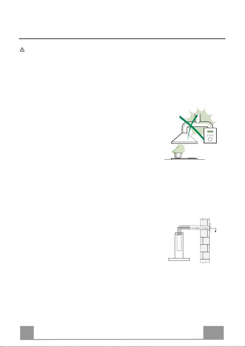
• Do not connect the extractor hood to exhaust ducts carrying combustion
fumes (boilers, fireplaces, etc.).
• If the extractor is used in conjunction with nonelectrical appliances (e.g. gas burning
appliances), a sufficient degree of aeration must
be guaranteed in the room in order to prevent the
backflow of exhaust gas. The kitchen must have
an opening communicating directly with the open
air in order to guarantee the entry of clean air.
When the cooker hood is used in conjunction with
appliances supplied with energy other than electric, the negative pressure in
the room must not exceed 0,04 mbar to prevent fumes being drawn back
into the room by the cooker hood.
• In the event of damage to the power cable, it must be replaced by the
manufacturer or by the technical service department, in order to prevent any
risks.
2°
EN
16
Page 18

• If the instructions for installation for the gas hob specify a greater distance
specified above, this has to be taken into account. Regulations concerning
the discharge of air have
• Use only screws and small parts in support of the hood.
Warning: Failure to install the screws or fixing device in accordance with
these instructions may result in electrical hazards.
• Connect the hood to the mains through a two-pole switch having a contact
gap of at least 3 mm.
to be fulfilled.
USE
• The extractor hood has been designed exclusively for domestic use to
eliminate kitchen smells.
• Never use the hood for purposes other than for which it has been designed.
• Never leave high naked flames under the hood when it is in operation.
• Adjust the flame intensity to direct it onto the bottom of the pan only, making
sure that it does not engulf the sides.
• Deep fat fryers must be continuously monitored
during use: overheated oil can burst into flames.
• Do not flambè under the range hood; risk of fire.
• This appliance can be used by children aged from
8 years and above and persons with reduced
physical, sensory or mental capabilities or lack of
experience and knowledge if they have been given supervision or instruction
concerning use of the appliance in a safe way and understand the hazards
involved. Children shall not play with the appliance. Cleaning and user
maintenance shall not be made by children without supervision.
EN
17
Page 19

• “CAUTION: Accessible parts may become hot when used with cooking
appliances.”
MAINTENANCE
• Switch off or unplug the appliance from the mains supply before carrying out
any maintenance work.
• Clean and/or replace the Filters after the specified time period (Fire hazard).
• The Grease filters must be cleaned every 2 months of operation, or more
frequently for particularly heavy usage, and can be washed in a dishwasher.
• The Activated charcoal filter is not washable and cannot be regenerated,
and must be replaced approximately every 4 months of operation, or more
frequently for particularly heavy usage.
• "Failure to carry out cleaning as indicated will result in a fire hazard".
• Clean the hood using a damp cloth and a neutral liquid detergent.
The symbol on the product or on its packaging indicates that this product
may not be treated as household waste. Instead it shall be handed over to the
applicable collection point for the recycling of electrical and electronic
equipment. By ensuring this product is disposed of correctly, you will help
prevent potential negative consequences for the environment and human
health, which could otherwise be caused by inappropriate waste handling of
this product. For more detailed information about recycling of this product,
please contact your local city office, your household waste disposal service or
the shop where you purchased the product.
EN
18
Page 20

CHARACTERISTICS
Dimensions
90
422
600-900-1200
422
150
354
MIN.545 - MAX.850
450
422
354
60
450
354
EN
600-900-1200
MIN.545 - MAX.850
450
60
600-900-1200
19
Page 21

INSTALLATION
MIN165-MAX448
403
Wall drilling and bracket fixing
150 150
III
BI-B
145
II
AI-A
II
CI-C
60
I. READ the instructions before assembling
II. Draw the points on the wall and drill 7 holes:
o AI-AII : Holes for the engine box support
o
o
III
BI-B
: Holes for the engine box support
CI-CII : Holes for security fixing
EN
!
20
Page 22

Insert screws 2x (Ø5x40)
III.
into the wall plugs in AI-AII without
tightening; then, hook to the body
hood grommets and tighten into the
points A'-A''
Secure the bracket of
IV.
the pipes with the
screws 3x (Ø5x40) in
III
BI-B
It is possible a security fixing using the holes
V.
C'-C" and screwing 2x (Ø5x40) from inside the
hood, after removing grease filters.
I
A
II
A
II
C
I
B
II
B
III
B
EN
21
Page 23

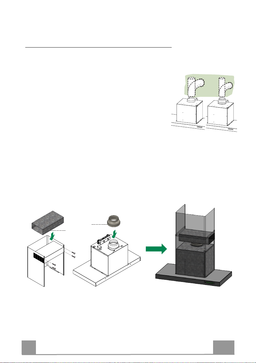
Connections
DUCTED VERSION AIR EXHAUST SYSTEM
When installing the ducted version, connect the hood to
the chimney using either a flexible or rigid pipe ø 150 or 120
mm, the choice of which is left to the installer.
To install a ø 120 mm air exhaust connection, insert the
•
reducer flange on the hood body outlet.
Fix the pipe in position using sufficient pipe clamps (not sup-
•
plied).
Remove any activated charcoal filters.
•
AIR OUTLET – RECIRCULATION VERSION
Fasten the Reducer Flange X to the Motor.
•
Fix the Air Outlet Connection T in the lower tube using 4 screws (4.2x6.5)
•
Proceed wirh assembling th
Make sure that the Activated charcoal odour filter has been fitted.
•
e tubes to the hood body.
ø 120ø 150
EN
T
X
22
Page 24

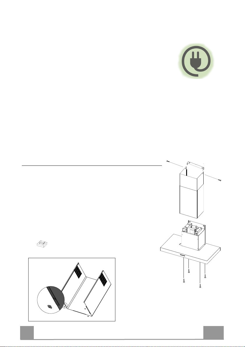
ELECTRICAL CONNECTION
The mains voltage must match that given on the ratings label
•
inside the hood itself. If the hood has a power plug, connect the
hood to an easily accessible regulatory power socket. If it does
not (direct connection to the mains), or the socket is not easily
accessible, install a two-pole regulatory switch to enable total
disconnection from the mains in case of category III overv
as required by th
stallation regulations.
e in
LED Replacement
!
For replacement contact technical support.
Tubes Assembly
Plug a set of pipes up to overlap to the engine
•
Upper Tube
Secure the sides to the brackets by using the 2 screws supplied
•
2x (Ø4x6)
oltage,
Lower Tube
It may be fixed, using the slots at the base of the lower
•
tube. In them, insert the cage nut 4x ( ) [see A ].
Then, after removing filters, tighten the screws 4x (M4x10)
from the bottom of the hood.
A
A
EN
23
Page 25

USE
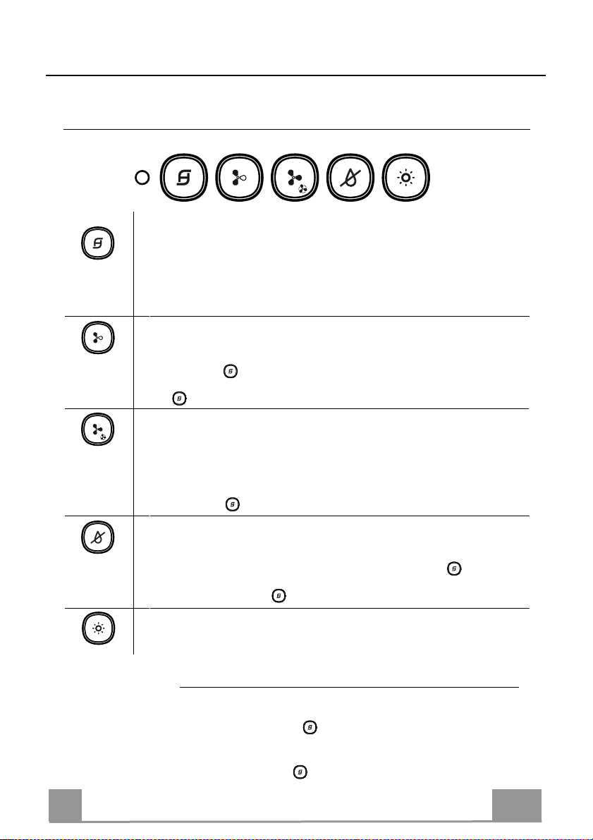
Control panel
Turns the motor on/off at speed one, the relevant button LED turns on, and stays
on at all speeds.
Press briefly to start the motor, if pressed by any speed the motor turns off.
With all the loads turned off (Motor and Light), if the filters alarm is active, reset
•
the alarm by pressing this button for approximately 2 seconds: all Leds will flash 3
times.
Turns the Motor on at speed two, the relevant button LED turns on only at 2° speed.
Press and hold the button for approximately 2 seconds, with all the loads turned
•
off (Motor and Lights), to turn the Activated Charcoal Filter alarm on. The LED
flashes twice to confirm. To turn the alarm off, press the button again and hold for
at least 2 seconds. The LED flashes once.
Turns the Motor on at speed three, the relevant button LED turns on only at 3° speed.
Press and hold the button for approximately 2 seconds to turns the Motor on at
•
INTENSIVE Speed, the LED flashes every 0.5”. This speed is timed to run for 6
minutes. At the end of this time, the system returns automatically to the
speed that was set before. If it is activated with the motor turned off, it will switch
to OFF at the end of the time. It is deactivated by pressing the same button, or any
speed button or the button to turn off the motor.
Turns the STEAM_SYSTEM on/off (this function is enabled only after starting the
regular aspiration). When the SoS is on, the relevant LED turns on.
With all the loads turned off (Motor and Light),pressing and holding the button
•
for approximately 2 seconds, the remote control is disabled, indicated by the LED
flashing just once. Pressing again, the remote control is enabled, indicated by the
LED flashing twice.
EN
Turns the lights ON/OFF and also the relevant LED.
FILT
ERS ALARM
The Metal Grease Filter saturation occurs after the Hood has been in
•
operation for 100 working hours, indicated by the LED flashing
every 1"
The Activated Charcoal Filter saturation occurs after the Hood has been
•
in operation for 200 working hours, ndicated by the LED flashing
every 0.5"
24
Page 26

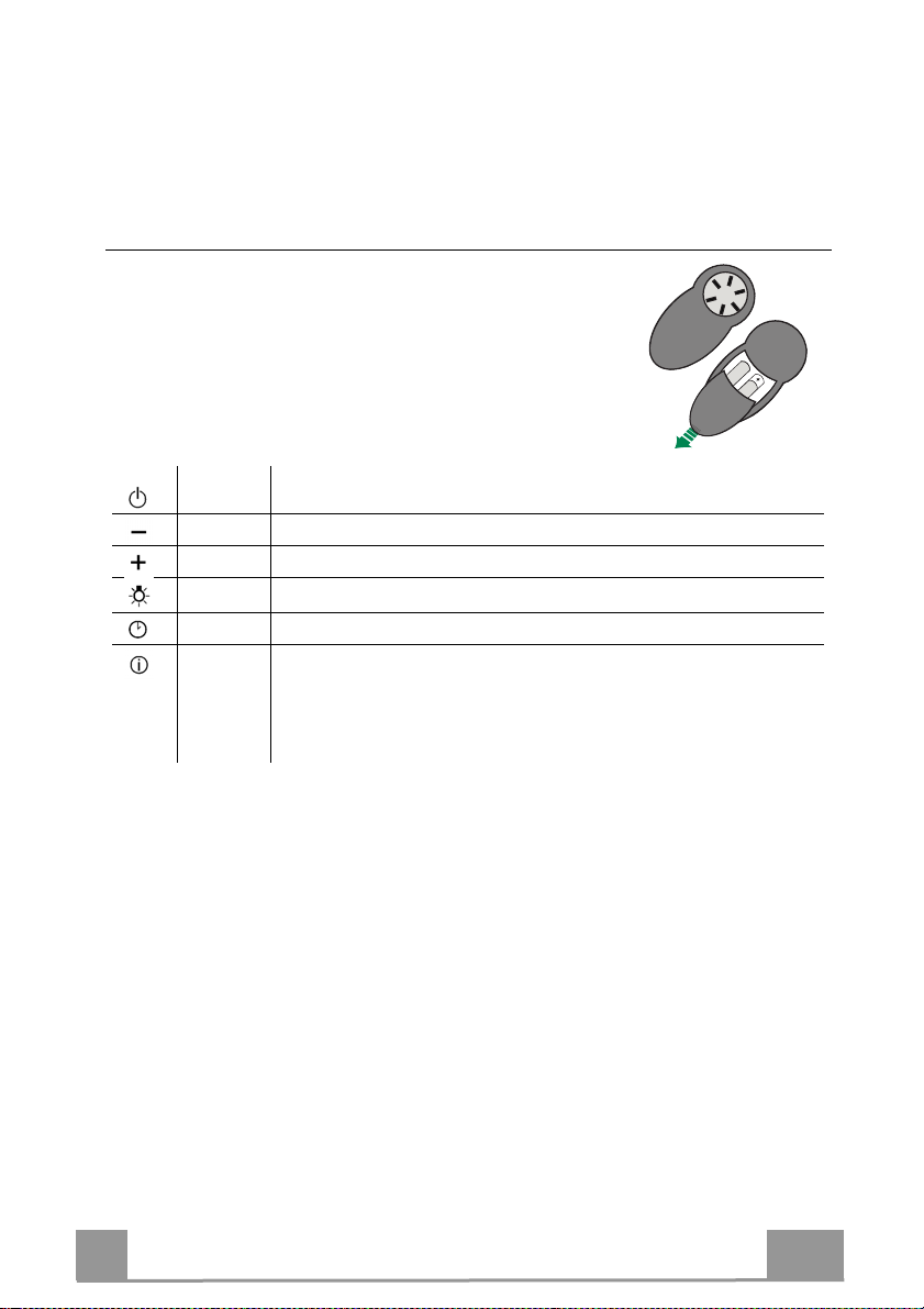
Remote Control (OPTIONAL)
The appliance can be controlled using a remote control
powered by a 1.5 V carbon-zinc alkaline batteries of the
standard LR03-AAA type (not included).
• Do not place the remote control near to heat sources.
• Used batteries must be disposed of in the proper manner.
Motor
Light Lights On / Off
Delay Function not implemented
Intensive
Motor On / Off on first speed. Long keypression to activate the
Steam_OFF_System
Decreases the working speed 3 > 2 > 1
Increases the working speed 1 > 2 > 3
Activates the INTENSIVE function. This speed is timed to run for 6 minutes.
At the end of this time, the system returns automatically to the
speed that was set before. If it is activated with the motor turned off, it will
switch to OFF at the end of the time. It is deactivated by pressing the same
button or the “Motor OFF”
EN
25
Page 27

FILTERS MAINTENANCE
Grease filters
CLEANING METAL SELF- SUPPORTING GREASE FILTERS
The filters must be cleaned every 2 months of operation, or
•
more frequently for particularly heavy usage, and can be
washed in a dishwasher.
Remove the filters one at a time by pushing them towards
•
the back of
Wash the filters, taking care not to bend them. Allow them
•
dry
When refitting the filters, make sure that the handle is visible
•
on the outside.
the group and pulling down at the
before refitting.
Activated charcoal filter (Recirculation version)
REPLACING THE ACTIVATED CHARCOAL FILTER
The filter is not washable and cannot be regenerated, and
•
must be replaced approximately every 4 months of
operation, or more frequently for particularly heavy usage.
Remove the metal grease filters.
•
Remove the saturated activated carbon filter by releasing
•
the fixing hooks.
Fit the new carbon filter by hooking it into its seating.
•
Refit the metal grease filters.
•
same
time.
to
SoS MAINTENANCE
The filters must be cleaned every 2 months of
•
operation, or more frequently for
particularly heavy usage.
Remove the grease filters.
•
Remove the SoS in his metalic shell,
•
unscrewing the 4 screws.
Clean the SoS with a damp cloth
•
and reassemble.
EN
26
Page 28

STEAM OFF SYSTEM
STEAM OFF
CONFORTEXCLUSIVO
SINCONDENSACIÓN
•
En las placas de inducción, el diferencial térmico que se crea entre la parte
caliente de la cocción y el aire más frío bajo la parte aspirante de la
campana provoca un efecto condensación y goteo que hasta hoy nadie
había conseguido resolver. La dispersión del vapor tiende además a
afectar al entorno próximo y a la parte estructural de la cocina como son
las puertas y las partes inferiores de los muebles. Con Steam Off System
todo ésto ha sido eliminado.
SYSTEM
UNACAMPANA
QUERESPIRA
•
Corrientes de aire controladas liberadas en forma helicoidal y con
geometría variable crean dos vórtices gracias a los cuáles se controla la
salida de humos y vapores. Con Steam Off System la campana no sólo
aspira sino que generan unas corrientes de aire que crean un movimiento
y aceleración vortical favoreciendo la recogida y la captación del vapor.
¡Se ha acabado la condensación y sus depósitos debajo y en torno a la
campana!
ES
27
Page 29

CONSEJOS Y SUGERENCIAS
Las instrucciones de uso se aplican a varios modelos de este aparato. Por lo
tanto, usted puede encontrar descripciones de características individuales que no
pertenecen a su aparato en concreto.
INSTALACIÓN
• El fabricante no se hace responsable de los daños provocados por una instalación
o uso indebido.
• La distancia mínima de seguridad entre el plano de
cocción y la campana extractora es de 650 mm
(algunos modelos pueden ser instalados a una altura
inferior; véase el párrafo relativo a las dimensiones de
trabajo y la instalación).
• Compruebe que la tensión de alimentación corresponda
a la indicada en la placa de datos colocada en el interior
de la campana.
• Para los aparatos de Clase I, compruebe que la red
eléctrica doméstica tenga una conexión a tierra adecuada.
Conecte la campana extractora al conducto de humo a través de un tubo con un
diámetro mínimo de 120 mm. La trayectoria del humo debe ser lo más corta
posible.
• No conecte la campana extractora a los conductos de humo que transportan humo
de combustión (ej. calderas, chimeneas, etc.).
• Si la campana extractora se utiliza en combinación con
aparatos no eléctricos (por ejemplo, aparatos de gas),
debe garantizarse un grado suficiente de ventilación en el
recinto para evitar el retorno del flujo de los gases de
escape. La cocina debe tener una abertura comunicante
directamente con el exterior para asegurar la entrada de
aire fresco. Cuando se utiliza la campana para cocina en
combinación con aparatos no alimentados por corriente eléctrica, la presión
negativa en el recinto no debe superar los 0,04 mbar para evitar que el humo sea
reaspirado en el recinto por la campana.
• En caso de daños en el cable de alimentación, éste debe ser sustituido por el
fabricante o el departamento de servicio para evitar cualquier riesgo.
2°
ES
28
Page 30

• Si las instrucciones de instalación del plano de cocción de gas especifican una
distancia mayor de la indicada anteriormente, es necesario tenerlo en cuenta. Se
tienen que respetar todas las normativas con respecto a la descarga del aire.
• Utilizar sólo los tornillos y accesorios metálicos de un tipo adecuado para la
campana.
Advertencia: No instalar tornillos o sujetadores de acuerdo con estas instrucciones
puede provocar descargas eléctricas.
• Conectar la campana a la alimentación de red interponiendo un interruptor bipolar
con distancia entre los contactos de por lo menos 3 mm.
USO
• La campana extractora está diseñada exclusivamente para uso doméstico, para
eliminar los olores de la cocina.
• Nunca utilice la campana para fines distintos de aquellos para los que fue diseñada.
• No deje nunca llamas altas bajo la campana cuando está en funcionamiento.
• Ajuste la intensidad de la llama para dirigirla sólo a la parte inferior del recipiente de
cocción, asegurándose de que no llegue a los lados.
• Las freidoras deben ser controladas continuamente
durante su uso: el aceite recalentado puede
incendiarse.
• No realice flambeados bajo la campana: se podría
producir un incendio.
• Este aparato puede ser usado por niños de edad no
inferior a 8 años y por personas con reducidas capacidades psicológicas, físicas y
sensoriales o con experiencia o conocimiento inadecuados, siempre que estén
cuidadosamente supervisados e instruidos sobre cómo utilizar de forma segura el
equipo y los peligros que esto implica. Asegúrese de que los niños no jueguen con
el aparato. La limpieza y mantenimiento por parte del usuario no deben ser
realizados por los niños, a menos que sean supervisados.
ES
29
Page 31

• ATENCIÓN: las partes accesibles pueden calentarse mucho durante el uso de
aparatos de cocción.
MANTENIMIENTO
• Apague o desconecte el aparato de la red eléctrica antes de cualquier operación de
limpieza o mantenimiento.
• Limpie y/o reemplace los filtros después del período de tiempo especificado (peligro
de incendio).
• Los filtros de grasa deben limpiarse cada 2 meses de operación, o con mayor
frecuencia si se utilizan muy frecuentemente y se pueden lavar en el lavavajillas.
• El filtro de carbón activo no se puede lavar ni regenerar, y se debe cambiar cada 4
meses de funcionamiento aproximadamente, o con mayor frecuencia si se utiliza
muy frecuentemente.
• “Existe el riesgo de incendio si la limpieza no se realiza conforme a las
instrucciones”.
• Limpie la campana con un paño húmedo y un detergente líquido suave.
El símbolo en el producto o en el embalaje indica que el producto no se debe
considerar un desecho doméstico normal. El producto a eliminar se debe llevar a un
centro de recogida apropiado para el reciclado de equipos eléctricos y electrónicos.
Mediante la eliminación de este producto de manera apropiada, se contribuye a evitar
consecuencias negativas para el medio ambiente y para la salud, que pudieran
derivarse de una eliminación inadecuada del producto. Para obtener informaciones
más detalladas sobre el reciclaje de este producto, ponerse en contacto con el
ayuntamiento, el servicio local de eliminación de desechos o la tienda donde se
compró el producto.
ES
30
Page 32

CARACTERÍSTICAS
Dimensiones
90
422
600-900-1200
422
150
354
MIN.545 - MAX.850
450
422
354
60
450
354
ES
600-900-1200
MIN.545 - MAX.850
450
60
600-900-1200
31
Page 33

INSTALACIÓN
MIN165-MAX448
403
Taladrado pared y fijación de las bridas
150 150
III
BI-B
145
II
AI-A
II
CI-C
60
I. LEA las instrucciones antes de los trabajos de montaje
II. Dibuja los puntos en la pared y perfore los 7 agujeros:
o AI-AII : Agujeros de fijación del soporte del motor
o
o
III
BI-B
: Agujeros de fijación del soporte del tubo
CI-CII : Agujeros para la fijación de seguridad
ES
!
32
Page 34

Introduzca los tornillos 2x (Ø5x40)
III.
en los anclajes de AI-AIi sin apretar;
adjuntar los ojales de motor
y apriete los puntos A'-A''
Fije el soporte de los tubos
IV.
con tornillos 3x (Ø5x40)
en posición BI-B
se puede tener un fijación de seguridad en C'-C" y
V.
atornillar 2x (Ø5x40) desde el interior de la campana, después
III
I
B
II
B
III
B
de quitar los filtros de grasa
I
A
II
A
II
C
ES
33
Page 35

Conexiones
SALIDA DEL AIRE VERSIÓN ASPIRANTE
Para la instalación de la versión aspirante, conectar la campana al
tubo de salida mediante un tubo rígido
mm, a discreción del instalador.
Para la conexión con el tubo de ø120 mm, introducir la brida de
•
reducción en la salida del cuerpo de la campana.
Fijar el tubo con abrazaderas adecuadas. Este material no se
•
proporciona en dotación.
Quitar los filtros antiolor al carbón activo.
•
•
Fijiar el racor de salida de aire T dentro de la chimenea inferior
con 4 tornillos (4.2x6.5).
Connectar la brida de reducción X en el motor.
•
Proceder con la fijación de los tubos a la campana.
Comprobar la presencia del filtro antiolor de carbón activo.
•
o flexible de ø150 o 120
SALIDA DE AIRE VERSIÓN FILTRANTE
ø 120ø 150
IT
T
X
34
Page 36

CONEXIÓN ELÉCTRICA
La tensión de red tiene que coincidir con el valor de tensión
•
indicado en la etiqueta de características que se encuentra en el
interior de la campana. Si el aparato tiene clavija, conectarla a
una toma conforme a las normas vigentes, situada en una zona
accesible. Si el aparato no tiene clavija (conexión directa a la red)
o la clavija queda en una zona inaccesible, se deberá aplicar un
interruptor bipolar conforme a las normas, que asegure la
desconexión completa de la red en las condiciones establecidas
por la categoría de sobretensión III, de conformidad con las
normas de instalación.
Reemplazo LED
!
Para el reemplazo , póngase en contacto con el soporte
técnico.
Montaje de la chimenea
Inserte la pareja de chimeneas para unirse con el motor
•
Chimenea superior
Fijar a los lados de las bridas con los 2 tornillos en dotación
•
2x (Ø4x6)
Chimenea inferior
se puede bloquear usando las ranuras en la base de la chim
•
inferior. Usted tiene que poner la tuerca de alojamiento
4x ( ) en las ranuras [ver A]. Entonces, después de quitar los
filtros, apretar los tornillos 4x (M4x10) desde la parte inferior de
la campana.
A
A
ES
enea
35
Page 37

USO
Panel de mandos
Enciende/Apaga el motor a la primera velocidad, el LED del botón correspondiente se
enciende y permanece encendido en todas las velocidades. Presionar brevemente para
arrancar el motor, si se presiona por cualquier otra velocidad el motor se apaga.
•
Con todas las cargas apagadas (motor y luz), si la alarma filtros está activo,
restablecer la alarma presionando este botón durante unos 2 segundos: Todos los
LED parpadearán 3 veces.
Enciende el motor a la velocidad dos, el LED del botón correspondiente se enciende
sólo en la segunda velocidad.
Pulse y mantenga pulsado el botón durante unos 2 segundos, con todas las cargas
•
apagadas (el motor y las luces), para activar la alarma de el filtro de carbón. El LED
parpadea dos veces para confirmar. Para desactivar la alarma, pulse de nuevo el
botón pulsado durante al menos 2 segundos. El LED parpadea una vez.
Enciende el motor a la velocidad 3, el LED del botón correspondiente se enciende sólo
en la 3^ velocidad.
Pulse y mantenga pulsado el botón durante unos 2 segundos para enciender el
•
motor a la velocidad INTENSIVA, el LED parpadea cada 0.5”segundo. Dicha
velocidad està temporizada en 6 minutos. Al final del tiempo el sistema regresa
a la velocidad implementada precedentemente. Si se activa con el motor apagado,
se cambia a OFF al final del tiempo. Se desactiva presionando la misma tecla, el
botón de cualquier velocidad o apagando el motor o con la tecla .
Enciende/Apaga el STEAM_SYSTEM on/off (la función se activa sólo después de iniciarla
aspiración regular). Cuando SoS está encendido, el LED correspondiente se enciende.
Con todas las cargas apagadas (Motor y Luz), manteniendo pulsado el botón
•
durante unos 2 segundos, el mando a distancia está desactivado, indicato por el
LED una sola vez. Si se pulsa de nuevo, el control remoto está activado, indicato
por el LED parpadeante dos veces.
ES
Enciende/Apaga las luces y también el LED correspondiente
ALARMA FILTROS
La saturación de los filtros antigrasa metálicos ocurre después de
•
oras de trabajo efectivo de la campana, indicato por el LED
100 h
que parpadea cada 1"
La saturación de los filtros de Carbón activo ocurre después de 100
•
horas de trab
parpadea cada 0.5"
ajo efectivo de la campana, indicato por el LED que
36
Page 38

Telecomandos (OPCIONAL)
El aparato puede comandarse con un mando a distancia
que funciona con pilas alcalinas zinkcarbón de 1,5 V del tipo
standard LR03-AAA (no incluido).
• No dejar el mando a distancia cerca de una fuente de
calor.
• Tirar las pilas, cuando se hayan agotado, en los
contenedores especiales colocados con dicho fin.
Motore
Luce Enciende/Apaga las luces
Delay Función no implementada
Intensiva
Enciende/Apaga el motor a la primera velocidad. Una presión prolongada
enciende el Steam_OFF_System
Decrementa la velocidad de ejercicio a cada presión 3 > 2 > 1
Incrementa la velocidad de ejercicio a cada presión 1 > 2 > 3
Enciender el motor a la velocidad INTENSIVA. Dicha velocidad està
temporizada en 6 minutos. Al final del tiempo el sistema regresa a la
velocidad implementada precedentemente. Si se activa con el motor
apagado, se cambia a OFF al final del tiempo. Se desactiva presionando la
misma tecla.
ES
37
Page 39

MANTENIMIENTO FILTROS
Filtros antigrasa
LIMPIEZA DE LOS FILTROS ANTIGRASA METÁLICOS
Se pueden lavar en el lavavajillas y requieren un lavado cada 2
•
meses aproximadamente o más a menudo si su uso es muy intenso.
Quitar los filtros uno por vez, operando en los enganches
•
co-rrespondientes.
Lavar los filtros evitando que se doblen y dejarlos secar antes
•
de volverlos a montar.
Montar los filtros prestando atención en mantener la
•
manija hacia la parte visible exterior..
Filtro antiolor (Versión filtrante)
SUSTITUCIÓN DEL FILTRO DE CARBÓN ACTIVO
No se puede lavar ni regenerar, se debe cambiar cada 4 meses
•
aproximadamente o más a menudo si su uso es muy intenso.
Quitar el filtro antigrasa metálico.
•
Quitar el filtro antiolor de carbón activo saturado, operando
•
en los enganches correspondientes.
Montar el nuevo filtro de carbón enganchándolo en su asiento.
•
Montar nuevamente el filtro antigrasa.
•
MANTENIMIENTO SoS
Requiere un lavado cada 2 meses aproximadamente
•
o más a menudo si
Quitar los filtro antigrasas.
•
Retire el SoS en su concha metálica,
•
aflojando los 4 tornillos.
Limpiar el SoS con un paño húmedo
•
y reensamblar.
ES
su uso es muy intenso.
38
Page 40

SCHEMA ELETTRICO - ELECTRIC DIAGRAM - ESQUEMA ELéCTRICO
SPEED 2
ARANCIONE (ORANGE)
ROSSO (RED)
IN 230Vac
L
NN
MOTOR 120W
1,2Watt
LED 350mA
1,2Watt
LED 350mA
NERO (BLACK)
ROSSO (RED)
NERO (BLACK)
ROSSO (RED)
NERO (BLACK)
ROSSO (RED)
ROSSO (RED)
ROSA (PINK)
NERO (BLACK)
VIOLA (PURPLE)
LUX1
LUX2
-
+
PRI
230v
SEC
In AC
DC 10W
350mA ku2
MOTOR
IR
ROSSO (RED)
ARANCIONE (ORANGE)
CELESTE (BLUE)
MARRONE (BROWN)
GIALLOVERDE (YELLOWGREEN)
1
2
1
2
ROSA (PINK)
VIOLA (PURPLE)
ARANCIONE (ORANGE)
ROSSO (RED)
CELESTE (BLUE)
GIALLOVERDE (YELLOWGREEN)
MARRONE (BROWN)
MARRONE (BROWN)
BLU (BLUE)
ROSSO (RED)
NERO (BLACK)
BIANCO (WHITE)
MARRONE (BROWN)
ARANCIONE (ORANGE)
1
234
5
6
123
456
BLU (BLUE)
ROSSO (RED)
NERO (BLACK)
BIANCO (WHITE)
ARANCIONE (ORANGE)
M
39
Page 41

__________________________________________________________
__________________________________________________________
__________________________________________________________
__________________________________________________________
__________________________________________________________
__________________________________________________________
__________________________________________________________
__________________________________________________________
__________________________________________________________
__________________________________________________________
__________________________________________________________
__________________________________________________________
__________________________________________________________
__________________________________________________________
__________________________________________________________
__________________________________________________________
__________________________________________________________
__________________________________________________________
__________________________________________________________
__________________________________________________________
__________________________________________________________
__________________________________________________________
__________________________________________________________
__________________________________________________________
__________________________________________________________
__________________________________________________________
__________________________________________________________
__________________________________________________________
__________________________________________________________
__________________________________________________________
__________________________________________________________
Page 42

__________________________________________________________
__________________________________________________________
__________________________________________________________
__________________________________________________________
__________________________________________________________
__________________________________________________________
__________________________________________________________
__________________________________________________________
__________________________________________________________
__________________________________________________________
__________________________________________________________
__________________________________________________________
__________________________________________________________
__________________________________________________________
__________________________________________________________
__________________________________________________________
__________________________________________________________
__________________________________________________________
__________________________________________________________
__________________________________________________________
__________________________________________________________
__________________________________________________________
__________________________________________________________
__________________________________________________________
__________________________________________________________
__________________________________________________________
__________________________________________________________
__________________________________________________________
__________________________________________________________
__________________________________________________________
__________________________________________________________
Page 43

Page 44

991.0._0- 1
D002588_0
3011000048700.04
 Loading...