

Page 1
INSTALLATION INSTRUCTIONS KIT LINE24ST
INSTRUCTIONS D'INSTALLATION KIT LINE24ST
Refer to Faber U&C Guides for Installation Instructions.
Reportez-vous aux guides Faber U&C pour les instructions d'installation.
Pre-Planning Your Installation - Important: The recommended height to install
this hood off the cooktop is a minimum of 24" electric cooking surfaces and
a maximum of 30” gas surfaces for maximum effectiveness. Also consult the
cooktop manufacturer’s recommendation.
Planiez votre installation - Important : La hauteur recommandée pour installer
cette hotte au-dessus de la surface de cuisson est d’un minimum de 24” surfaces
de cuisson électriques et d’un maximum de 30” surfaces de gaz pour un ma-
ximum d’efcacité. De plus, nous vous recommandons consulter le manuel de
recommandations du fabricant de la surface de cuisson.
Page 2
The Inca Smart requires 5" round ductwork. To ensure that the blower performs to its
highest possible capacity, ductwork should be as short and straight as possilbe.
Make your ductrun as straight and short as possible. The ductrun should not exceed 25
equivalent feet if ducted with the required minimum of 5" round duct. Count 45º angles
as 3 feet, 90º elbows as 5 feet, and 90º at elbows as 12 feet.
For best results, use no more than three 90° elbows. Make sure that there is a minimum
of 24" of straight duct between elbows if more than one is used. Do not install two
elbows together. If you must elbow right away, do it as far away from the hood's
exhaust opening as possible.
FOR INSTALLATIONS WITH LINERS
PARTS SUPPLIED FOR INSTALLATION
• 1 Backdraft Damper
• 10 Screws
• Field Wiring Box
• 1 Literature Package
PARTS NEEDED FOR INSTALLATION
• 2 Conduit Connectors
• Power Supply Cable
• Scews for Field Wiring Box
• 1 Wall or Roof Cap
• All Metal Ductwork
OPTIONAL ACCESSORIES AVAILABLE
• Charcoal Filter Kit
For recirculating installations only,
replace charcoal lters as needed
part # FILTER4
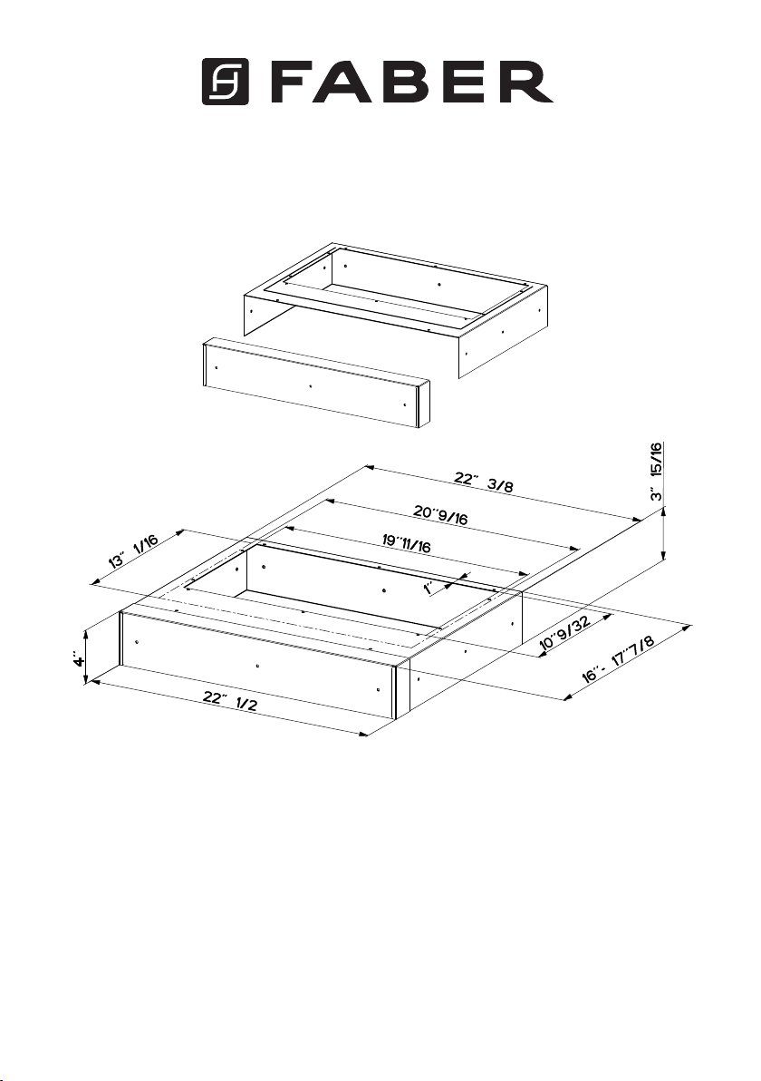
• Liners
Create a perfectly-sealed, non-combustible
perimeter around the Inca Smart. Depth adjustable
from 16" - 17
7/8"
.
Standard Liner 30 Stainless - part #
LINE30ST
Standard Liner 36 Stainless - part #
LINE36ST
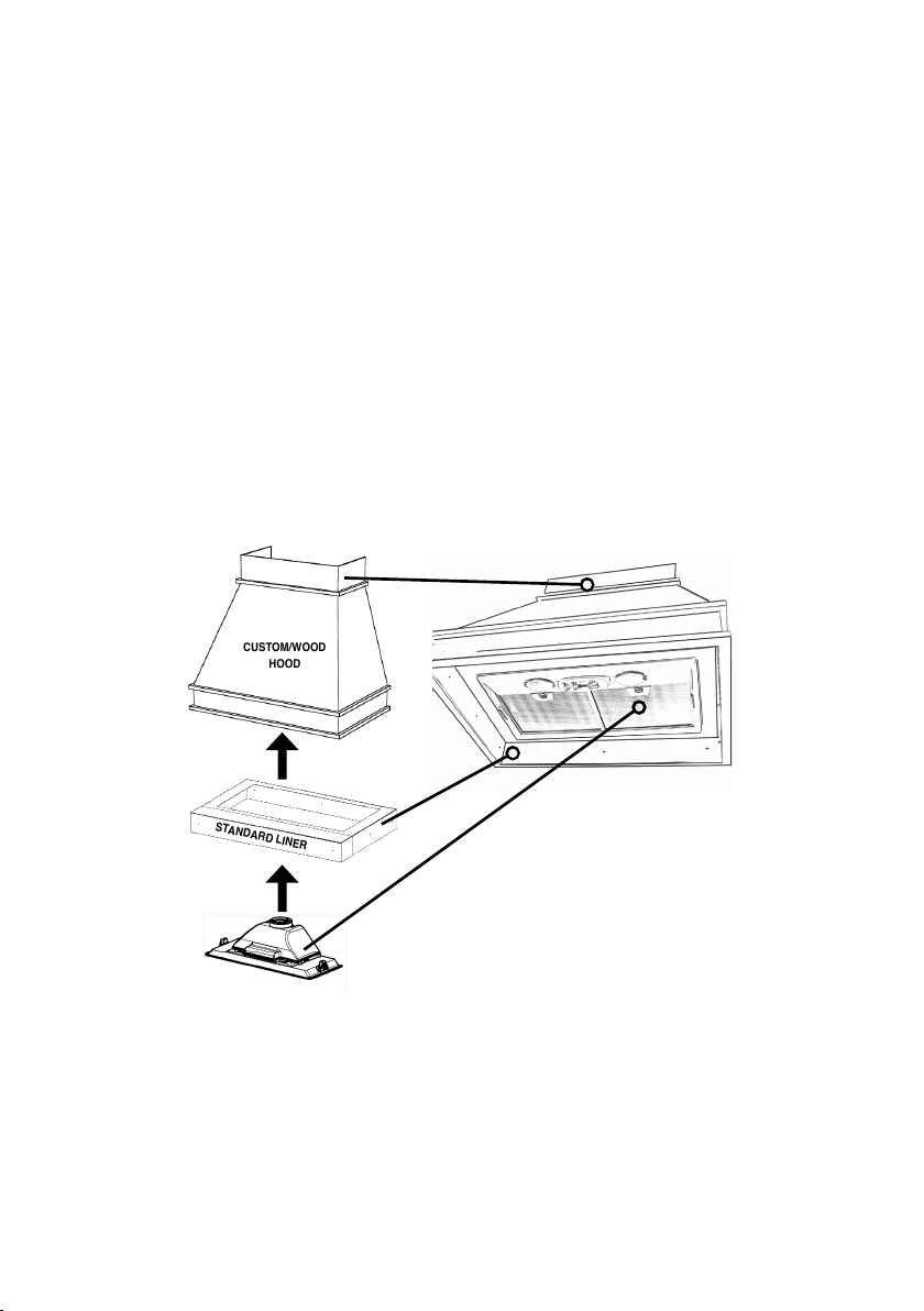
CUSTOM/WOOD
HOOD
STANDARD LINER
INCA SMART
FOR INSTALLATION WITH LINERS
1. The custom/wood hood must have a sturdy base (3/4" plywood recommended)
to accomodate the cut-out for the Hood. The base must be recessed to accomodate the height of the Liner. The Liner attaches to the bottom of the base using
screws appropriate for the size and material of your custom/wood hood. The
Hood inserts into the cut-out in the Liner and base.
2.Position the rear section of the Liner so that it abuts the back edge of your
hood. Using a pen, trace the outline of the pre-cut out. Install both sections of the
Liner and proceed to INSTALL THE RANGEHOOD.
2
Page 3

The Inca Smart requires 5" round ductwork. To ensure that the blower performs to its
highest possible capacity, ductwork should be as short and straight as possilbe.
Make your ductrun as straight and short as possible. The ductrun should not exceed 25
equivalent feet if ducted with the required minimum of 5" round duct. Count 45º angles
as 3 feet, 90º elbows as 5 feet, and 90º at elbows as 12 feet.
For best results, use no more than three 90° elbows. Make sure that there is a minimum
of 24" of straight duct between elbows if more than one is used. Do not install two
elbows together. If you must elbow right away, do it as far away from the hood's
exhaust opening as possible.
FOR INSTALLATIONS WITH LINERS
PARTS SUPPLIED FOR INSTALLATION
• 1 Backdraft Damper
• 10 Screws
• Field Wiring Box
• 1 Literature Package
PARTS NEEDED FOR INSTALLATION
• 2 Conduit Connectors
• Power Supply Cable
• Scews for Field Wiring Box
• 1 Wall or Roof Cap
• All Metal Ductwork
OPTIONAL ACCESSORIES AVAILABLE
• Charcoal Filter Kit
For recirculating installations only,
replace charcoal lters as needed
part # FILTER4
• Liners
Create a perfectly-sealed, non-combustible
perimeter around the Inca Smart. Depth adjustable
from 16" - 17
7/8"
.
Standard Liner 30 Stainless - part #
LINE30ST
Standard Liner 36 Stainless - part #
LINE36ST
CUSTOM/WOOD
HOOD
STANDARD LINER
INCA SMART
INSTALLATIONS AVEC CADRES
1.La hotte encastrable doit avoir une base vigoureuse (3/4” contre-plaqué recommandé) pour adapter au coupe-circuit pour la hotte. La base doit être enfoncée
pour adapter à la taille du Cadre. Les attaches de Cadre au fond de la base à
l’aide des vis appropriées pour la hotte encastrable. La hotte est installé dans le
coupe-circuit dans le Cadre et la base.
2.Placez la section arrière du Cadre de sorte qu’il aboute le bord arrière de votre
hotteencastrable. En utilisant un stylo, tracez le contour de la sortie précoupée.
Installez les deux sections du Cadre et procédez INSTALLATION DE LA HOTTE.
3
Page 4

991.0554.842_02 - 190206
D00004932_01
 Loading...