

Faber LI_991.0431.691 Instruction Manual

Felhasználói Kézikönyv
Instructions Manual
Manuel d’Instructions
Bedienungsanleitung
Gebruiksaanwijzing
Manual de instrucciones
Εγχειρίδιο οδηγιών
Руководство по эксплуатации
Kullanim Kilavuzu
Naudojimosi instrukcija
Instrukcijas Grāmata
Kasutusjuhend

2
2
INDEX
RECOMMENDATIONS AND SUGGESTIONS ..................................................................................................................... 4
CHARACTERISTICS ............................................................................................................................................................. 7
INSTALLATION...................................................................................................................................................................... 8
USE ...................................................................................................................................................................................... 11
MAINTENANCE................................................................................................................................................................... 13
SOMMAIRE
CONSEILS ET SUGGESTIONS.......................................................................................................................................... 15
CARACTERISTIQUES......................................................................................................................................................... 18
INSTALLATION.................................................................................................................................................................... 19
UTILISATION ....................................................................................................................................................................... 22
ENTRETIEN......................................................................................................................................................................... 24
INHALTSVERZEICHNIS
EMPFEHLUNGEN UND HINWEISE ................................................................................................................................... 26
CHARAKTERISTIKEN......................................................................................................................................................... 29
MONTAGE ........................................................................................................................................................................... 30
BEDIENUNG........................................................................................................................................................................ 33
WARTUNG........................................................................................................................................................................... 35
INHOUDSOPGAVE
ADVIEZEN EN SUGGESTIES............................................................................................................................................. 37
EIGENSCHAPPEN .............................................................................................................................................................. 40
INSTALLATIE....................................................................................................................................................................... 41
GEBRUIK ............................................................................................................................................................................. 44
ONDERHOUD...................................................................................................................................................................... 46
ÍNDICE
CONSEJOS Y SUGERENCIAS........................................................................................................................................... 48
CARACTERÍSTICAS ........................................................................................................................................................... 51
INSTALACIÓN ..................................................................................................................................................................... 52
USO...................................................................................................................................................................................... 55
MANTENIMIENTO............................................................................................................................................................... 57
ΠΕΡΙΕΧΟΜΕΝΑ
ΣΥΜΒΟΥΛΕΣ ΚΑΙ ΣΥΣΤΑΣΕΙΣ............................................................................................................................................ 59
ΧΑΡΑΚΤΗΡΙΣΤΙΚΑ............................................................................................................................................................... 62
ΕΓΚΑΤΑΣΤΑΣΗ.................................................................................................................................................................... 63
ΧΡΗΣΗ ................................................................................................................................................................................. 66
ΣΥΝΤΗΡΗΣΗ........................................................................................................................................................................ 68
EN
FR
DE
NL
ES
GR

3
3
УКАЗАТЕЛЬ
СОВЕТЫ И РЕКОМЕНДАЦИИ .......................................................................................................................................... 70
ХАРАКТЕРИСТИКИ............................................................................................................................................................ 73
УСТАНОВКА........................................................................................................................................................................ 74
ЭКСПЛУАТАЦИЯ................................................................................................................................................................ 77
УХОД.................................................................................................................................................................................... 79
IÇERIKLER
TAVSİYELER VE ÖNERİLER.............................................................................................................................................. 81
ÖZELLIKLER........................................................................................................................................................................ 84
MONTAJ............................................................................................................................................................................... 85
KULLANIM ........................................................................................................................................................................... 88
BAKIM .................................................................................................................................................................................. 90
TURINYS
PATARIMAI IR NUORODOS............................................................................................................................................... 92
PRIETAISO APRAŠYMAS .................................................................................................................................................. 95
MONTAVIMAS..................................................................................................................................................................... 96
NAUDOJIMAS...................................................................................................................................................................... 99
VALYMAS IR PRIEŽIŪRA ................................................................................................................................................. 101
INDEKSS
IETEIKUMI UN PRIEKŠLIKUMI......................................................................................................................................... 103
TEHNISKIE DATI............................................................................................................................................................... 106
UZSTĀDĪŠANA.................................................................................................................................................................. 107
IZMANTOŠANA ................................................................................................................................................................. 110
APKOPE............................................................................................................................................................................. 112
INDEKS
SOOVITUSED JA ETTEPANEKUD................................................................................................................................... 114
OMADUSED....................................................................................................................................................................... 117
PAIGALDAMINE ................................................................................................................................................................ 118
KASUTAMINE.................................................................................................................................................................... 121
HOOLDUS.......................................................................................................................................................................... 123
MUTATÓUJJ
TANÁCSOK ÉS JAVASLATOK .........................................................................................................................................125
JELLEMZŐK ...................................................................................................................................................................... 128
FELSZERELÉS.................................................................................................................................................................. 129
HASZNÁLAT ...................................................................................................................................................................... 132
KARBANTARTÁS .............................................................................................................................................................. 134
RU
TR
LT
LV
EE
HU

EN
4
4
RECOMMENDATIONS AND SUGGESTIONS
The Instructions for Use apply to several versions of this appliance.
Accordingly, you may find descriptions of individual features that do not
apply to your specific appliance.
INSTALLATION
• The manufacturer will not be held liable for any damages resulting from
incorrect or improper installation.
• The minimum safety distance between the cooker top and the extractor hood
is 650 mm (some models can be installed at a lower height, please refer to
the paragraphs on working dimensions and installation).
• Check that the mains voltage corresponds to that indicated on the rating
plate fixed to the inside of the hood.
• For Class I appliances, check that the domestic power supply guarantees
adequate earthing.
Connect the extractor to the exhaust flue through a pipe of minimum
diameter 120 mm. The route of the flue must be as short as possible.
• Do not connect the extractor hood to exhaust ducts
carrying combustion fumes (boilers, fireplaces, etc.).
• If the extractor is used in conjunction with non-electrical
appliances (e.g. gas burning appliances), a sufficient
degree of aeration must be guaranteed in the room in
order to prevent the backflow of exhaust gas. The
kitchen must have an opening communicating directly
with the open air in order to guarantee the entry of clean air. When the
cooker hood is used in conjunction with appliances supplied with energy
other than electric, the negative pressure in the room must not exceed 0,04
mbar to prevent fumes being drawn back into the room by the cooker hood.
• The air must not be discharged into a flue that is used for
exhausting fumes from appliances burning gas or other
fuels (not applicable to appliances that only discharge the
air back into the room).
• In the event of damage to the power cable, it must be
replaced by the manufacturer or by the technical service
department, in order to prevent any risks.
2°

EN
5
5
• If the instructions for installation for the gas hob specify a greater distance
specified above, this has to be taken into account. Regulations concerning
the discharge of air have to be fulfilled.
• Use only screws and small parts in support of the hood.
Warning: Failure to install the screws or fixing device in accordance with
these instructions may result in electrical hazards.
• Connect the hood to the mains through a two-pole switch having a contact
gap of at least 3 mm.
USE
• The extractor hood has been designed exclusively for domestic use to
eliminate kitchen smells.
• Never use the hood for purposes other than for which it has been designed.
• Never leave high naked flames under the hood when it is in operation.
• Adjust the flame intensity to direct it onto the bottom of the pan only, making
sure that it does not engulf the sides.
• Deep fat fryers must be continuously monitored
during use: overheated oil can burst into flames.
• Do not flambè under the range hood; risk of fire.
• This appliance can be used by children aged from
8 years and above and persons with reduced
physical, sensory or mental capabilities or lack of
experience and knowledge if they have been given supervision or instruction
concerning use of the appliance in a safe way and understand the hazards
involved. Children shall not play with the appliance. Cleaning and user
maintenance shall not be made by children without supervision.
• This appliance is not intended for use by persons (including children) with
reduced physical, sensory or mental capabilities, or lack of experience and
knowledge, unless they have been given supervision or instruction
concerning use of the appliance by a person responsible for their safety.

EN
6
6
• “CAUTION: Accessible parts may become hot when used with cooking
appliances.”
MAINTENANCE
• Switch off or unplug the appliance from the mains supply before carrying out
any maintenance work.
• Clean and/or replace the Filters after the specified time period (Fire hazard).
• The Grease filters must be cleaned every 2 months of operation, or more
frequently for particularly heavy usage, and can be washed in a dishwasher.
• The Activated charcoal filter is not washable and cannot be regenerated,
and must be replaced approximately every 4 months of operation, or more
frequently for particularly heavy usage.
• "Failure to carry out cleaning as indicated will result in a fire hazard".
• Clean the hood using a damp cloth and a neutral liquid detergent.
The symbol on the product or on its packaging indicates that this product
may not be treated as household waste. Instead it shall be handed over to the
applicable collection point for the recycling of electrical and electronic
equipment. By ensuring this product is disposed of correctly, you will help
prevent potential negative consequences for the environment and human
health, which could otherwise be caused by inappropriate waste handling of
this product. For more detailed information about recycling of this product,
please contact your local city office, your household waste disposal service or
the shop where you purchased the product.

EN
7
7
CHARACTERISTICS
Dimensions
ø150
247
360
400
905
1000
1000
962
582
8
68
377
532
493
820 - 1140
252
740
80
ø120
ø150
ø120
532
493
820 - 1140
252
900
147
325
400
606
900
310
78
122
740
377
68
582
962
8
Components
Ref. Q.ty Product Components
1 1 Hood Body, complete with: Controls, Light, Blower,
Filters
2 1 Telescopic Chimney comprising:
2.1 1 Upper Section
2.2 1 Lower Section
9 1 Reducer Flange ø 150-120 mm
14.1 2 Air Outlet Connection Extension
15 1 Air Outlet Connection
Ref. Q.ty Installation Components
7.1 1 Hood Connector Support
7.2.1 2 Upper Chimney Section Fixing Brackets
11 12 Wall Plugs
12a 12 Screws 4,2 x 44,4
12e 6 Screws 2,9 x 9,5
12r 2 Screws 4,2 x 12,7
Q.ty Documentation
1 Instruction Manual
12a
11
7.1
2.1
2.2
2
1
9
14.1
15
12a
7.2.1
11
12r
12e

EN
8
8
INSTALLATION
Wall drilling and bracket fixing
357
X
1÷2
650 min.
7.2.1
7.1
12a
11
11
12a
12r
Wall marking:
• Draw a horizontal line at 650 mm above the hob.
• Place bracket 7.2.1 on the wall as shown about 1-2 mm from the ceiling or upper limit.
• Mark the wall at the centres of the holes in the bracket.
• Place bracket 7.2.1 on the wall as shown at X mm below the first bracket (X = height of the
upper chimney section supplied).
• Mark the wall at the centres of the holes in the bracket.
• Place the Hood Connector Support 7.1 on the wall as shown at 357 mm above the horizontal
reference line, making sure that the holes used to fix the corner to the wall are equidistant.
• Mark the wall at the centres of the holes in the Support.
• Drill ø 8 mm holes at all the centre points marked.
• Insert the wall plugs 11 in the holes.
• Fix the brackets and the Support using the 12a (4,2 x 44,4) screws supplied.
• Insert the two screws 12r (4,2 x 12,7) supplied in the hood body fixing holes, located on the
front plate of the Hood Connector Support, leaving a gap of 5-6 mm between the Support
and the head of the screw.
EN
9
9
Mounting the hood body
• Before attaching the hood body, tighten the two screws Vr lo-
cated on the hood body mounting points.
• Hook the hood body onto the screws 12r (4,2 x 12,7).
• Fully tighten support screws 12r (4,2 x 12,7).
• Adjust screws Vr to level the hood body.
12r
Vr
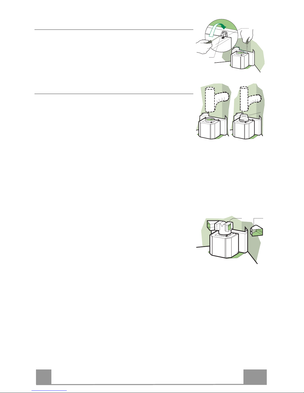
Connections
DUCTED VERSION AIR EXHAUST SYSTEM
When installing the ducted version, connect the hood to the
chimney using either a flexible or rigid pipe ø 150 or 120 mm,
the choice of which is left to the installer.
• To install a ø 120 mm air exhaust connection, insert the re-
ducer flange 9 on the hood body outlet.
• Fix the pipe in position using sufficient pipe clamps (not supplied).
• Remove possible charcoal filters.
ø 150
9
ø 120
RECIRCULATION VERSION AIR OUTLET
• Push fit connection 15 onto the hood body outlet.
• Insert the connection extension pieces laterally 14.1 in connection 15.
• Make sure that the outlet of the extension pieces 14.1 is horizontally and vertically aligned with the chimney outlets. If this
is not the case, adjust the position by either reversing the connection extension pieces 14.1 and then reassemble as described
previously.
• Ensure that the activated charcoal filters have been inserted.
14.1
15

EN
1
10
ELECTRICAL CONNECTION
• Connect the hood to the mains through a two-pole switch having a contact gap of at least 3 mm.
• Remove the grease filters (see paragraph Maintenance) being
sure that the connector of the feeding cable is correctly inserted
in the socket placed on the side of the fan.
Chimney assembly
Upper exhaust Chimney
• Slightly widen the two sides of the upper chimney and hook
them behind the brackets 7.2.1, making sure that they are well
seated.
• Secure the sides to the brackets using the 4 screws 12c (2,9 x
9,5) supplied.
Lower exhaust Chimney
• Slightly widen the two sides of the chimney and hook them
between the upper chimney and the wall, making sure that they
are well seated.
• Fix the lower part laterally to the hood body using the 2 screws
12c (2,9 x 9,5) supplied.
7.2.1
2.1
2.2
2
12e
12e

EN
1
11
USE
L
V1 V2 V3
S
0 - 1
MID
MAX
0 - 1
L Light Switches the lighting system on and off.
S Led Motor running led.
V1 Motor Switches the extractor motor on and off at low speed. Used to provide a
continuous and silent air change in the presence of light cooking vapours.
V2 Speed Medium speed, suitable for most operating conditions given the optimum
treated air flow/noise level ratio.
V3 Speed Maximum speed, used for eliminating the highest cooking vapour emission,
including long periods.

EN
1
12
T2
T1
L
T3
Control panel
BUTTON LED FUNCTIONS
T1 Speed On Turns the Motor on at Speed one.
Turns the Motor off.
T2 Speed On Turns the Motor on at Speed two.
T3 Speed Fixed When pressed briefly, turns the Motor on at Speed three.
Flashing Pressed for 2 Seconds.
Activates Speed four with a timer set to 6 minutes, after which
it returns to the speed that was set previously. Suitable to deal
with maximum levels of cooking fumes.
L Light Turns the Lighting System on and off.
Warning: Button T1 turns the motor off, after first passing to speed one.

EN
1
13
MAINTENANCE
Grease filters
CLEANING METAL SELF- SUPPORTING GREASE FILTERS
• The filters must be cleaned every 2 months of operation, or
more frequently for particularly heavy usage, and can be
washed in a dishwasher.
• Remove the filters one at a time by pushing them towards the
back of the group and pulling down at the same time.
• Wash the filters, taking care not to bend them. Allow them to
dry before refitting.
• When refitting the filters, make sure that the handle is visible
on the outside.
Activated charcoal filter (Recirculation version)
REPLACING THE ACTIVATED CHARCOAL FILTER
• The filter is not washable and cannot be regenerated, and must
be replaced approximately every 4 months of operation, or
more frequently for particularly heavy usage.
• Remove the metal grease filters.
• Remove the saturated activated carbon filter by releasing the
fixing hooks.
• Fit the new filter by hooking it into its seating.
• Refit the metal grease filters.

EN
1
14
Lighting
LIGHT REPLACEMENT
20 W halogen light.
• Remove the 2 screws fixing the Lighting support, and
pull it out of from the Hood.
• Extract the lamp from the Support.
• Replace with another of the same type, making sure
that the two pins are properly inserted in the lamp
holder socket holes.
• Refit the Support, fixing it in place with the two
screws removed as above.
Lamp Power (W) Socket Voltage (V) Dimension (mm) ILCOS Code
28 E14 220 – 240 104 x 35
HSGSB/C/UB-28-220/240-E14
28 E14 230 85x25
HDG-28-230-E14-25
20 G4 12 33 x 9 HSG/C/UB-20-12-G4
35 GU10 230 51 x 50,7 HAGS-35-230-GU10-51/40
50 GU10 230 51 x 50,7 HAGS-35-230-GU10-51/20
20 GU4 12 40 x 35 HRGS-20-12-GU4-35/30
20 GU5.3 12 46 x 51 HRGS-20-12-GU5.3-50/10
16 G13 95 720 x 26
FD-16/40/1B-E-G13-26/720
18 G13 57 589,8 x 26
FD-18/40/1B-E-G13-26/600
9 G23
60 (lamp)
220-240 (starter)
167 x 28 FSD-9/27/1B-I-G23
11 G23
91 (lamp)
220-240 (starter)
235,8 x 28 FSD-11/40/1B-I-G23

FR
1
15
CONSEILS ET SUGGESTIONS
Les instructions pour l’utilisation se réfèrent aux différents modèles de cet
appareil. Par conséquent, certaines descriptions de caractéristiques particulières
pourraient ne pas appartenir spécifiquement à cet appareil.
INSTALLATION
• En aucun cas le fabricant ne peut être tenu pour responsable d’éventuels
dommages dus à une installation ou à une utilisation impropre.
• La distance de sécurité minimum entre le plan de cuisson et la
hotte aspirante est de 650 mm (certains modèles peuvent être
installés à une hauteur inférieure ; voir le paragraphe
concernant les dimensions de travail et l’installation).
• Assurez-vous que la tension de votre secteur correspond à
celle indiquée sur la plaque des données appliquée à l’intérieur de la hotte.
• Pour les appareils de Classe I, s’assurer que l’installation électrique de votre
intérieur dispose d’une mise à la terre adéquate.
Relier l’aspirateur au conduit de cheminée avec un tube d’un diamètre minimum
de 120 mm. Le parcours des fumées doit être le plus court possible.
• Ne pas relier la hotte aspirante aux conduits de cheminée qui
acheminent les fumées de combustion (par exemple de
chaudières, de cheminées, etc.).
• Si vous utilisez l’aspirateur en combinaison avec des
appareils non électriques (par ex. appareils à gaz), vous
devez garantir un degré d’aération suffisant dans la pièce,
afin d’empêcher le retour du flux des gaz de sortie. La cuisine doit présenter une
ouverture communiquant directement vers l’extérieur pour garantir l’amenée d’air
propre. Si vous utilisez la hotte de cuisine en combinaison avec des appareils non
alimentés à l’électricité, la pression négative dans la pièce ne doit pas dépasser
0,04 mbar afin d’éviter que la hotte ne réaspire les fumées dans la pièce.
• Ne pas évacuer l’air à travers un tube flexible utilisé pour l’aspiration des fumées
des appareils alimentés au gaz ou avec d’autres combustibles (ne pas utiliser
avec des appareils ayant une seule sortie d’air dans la pièce).
• Si le cordon d’alimentation est endommagé, veuillez le faire remplacer par le
fabricant ou par un service après-vente agréé pour éviter tout risque d’accident.
2°

FR
1
16
• Si les instructions d’installation du plan de cuisson à gaz spécifient une distance
supérieure à celle indiquée ci-dessus, veuillez impérativement en tenir compte.
Toutes les normes concernant l’évacuation de l’air doivent être respectées.
• Utiliser exclusivement des vis et des petites pièces du type adapté pour la hotte.
Attention : toute installation des vis et des dispositifs de fixation non conforme aux
présentes instructions peut entraîner des risques de décharges électriques.
• Brancher la hotte à l’alimentation de secteur avec un interrupteur bipolaire ayant une
ouverture des contacts d’au moins 3 mm.
UTILISATION
• Cette hotte aspirante a été conçue exclusivement pour un usage domestique, dans
le but d’éliminer les odeurs de cuisine.
• Ne jamais utiliser la hotte pour des objectifs différents de ceux pour lesquels elle a
été conçue.
• Ne jamais laisser un feu vif allumé sous la hotte lorsque celle-ci est en fonction.
• Régler l’intensité du feu de manière à l’orienter exclusivement vers le fond de la
casserole, en vous assurant qu’il ne déborde pas sur les côtés.
• Contrôler constamment les friteuses durant leur utilisation : l’huile surchauffée risque
de s’incendier.
• Ne pas flamber des mets sous la hotte : sous risque de
provoquer un incendie.
• Cet appareil n’est pas destiné à être utilisé par des enfants
d’un âge inférieur à 8 ans, ni par des personnes dont les
capacités physiques, sensorielles ou mentales sont
diminuées ou qui ont une expérience et des connaissances insuffisantes, à moins
que ces enfants ou ces personnes ne soient attentivement surveillés et instruits sur
la manière d’utiliser cet appareil en sécurité et sur les dangers que cela comporte.
Assurez-vous que les enfants ne jouent pas avec cet appareil. Le nettoyage et
l’entretien de la part de l’utilisateur ne doivent pas être effectués par des enfants, à
moins que ce ne soit sous la surveillance d’une personne responsable.
• Cet appareil n’est pas destiné à être utilisé par des personnes (enfants compris)
dont les capacités physiques, sensorielles ou mentales sont diminuées ou ayant
une expérience et des connaissances insuffisantes, à moins que ces personnes ne
soient attentivement surveillées et instruites par un responsable de leur sécurité.

FR
1
17
• ATTENTION : les parties accessibles peuvent devenir très chaudes durant
l’utilisation des appareils de cuisson.
ENTRETIEN
• Avant d’effectuer toute opération de nettoyage et d’entretien, éteindre ou
débrancher l’appareil du secteur.
• Nettoyer et/ou remplacer les filtres après le délai indiqué (danger
d’incendie).
• Nettoyer les filtres à graisse tous les 2 mois de fonctionnement ou plus
souvent en cas d’utilisation particulièrement intense. Ces filtres peuvent être
lavés au lave-vaisselle.
• Le filtre à charbon actif ne peut être ni lavé ni régénéré et il doit être
remplacé environ tous les 4 mois de fonctionnement ou plus souvent en cas
d’utilisation particulièrement intense.
• Effectuer le nettoyage selon les instructions, sous risque d'incendie.
• Nettoyer la hotte avec un chiffon humide et un détergent liquide neutre.
Le symbole marqué sur le produit ou sur son emballage indique que ce
produit ne peut pas être éliminé comme déchet ménager normal. Lorsque ce
produit doit être éliminé, veuillez le remettre à un centre de collecte prévu pour
le recyclage du matériel électrique et électronique. En vous assurant que cet
appareil est éliminé correctement, vous participez à prévenir des
conséquences potentiellement négatives pour l'environnement et pour la
santé, qui risqueraient de se présenter en cas d’élimination inappropriée. Pour
toute information supplémentaire sur le recyclage de ce produit, contactez
votre municipalité, votre déchetterie locale ou le magasin où vous avez acheté
ce produit.

FR
1
18
CARACTERISTIQUES
Encombrement
ø150
247
360
400
905
1000
1000
962
582
8
68
377
532
493
820 - 1140
252
740
80
ø120
ø150
ø120
532
493
820 - 1140
252
900
147
325
400
606
900
310
78
122
740
377
68
582
962
8
Composants
Réf. Q.té Composants de Produit
1 1 Corps Hotte équipé de:Comandes, Lumière, Groupe
Ventilateur, Filtres
2 1 Cheminée Télescopique formée de :
2.1 1 Cheminée Supérieure
2.2 1 Cheminée Inférieure
9 1 Flasque de Réduction ø 150-120 mm
14.1 2 Rallonge Raccord Sortie Air
15 1 Raccord Sortie Air
Réf. Q.té Composants pour l ’installation
7.1 1 Support de Fixation de la Hotte
7.2.1 2 Brides Fixation Cheminée Supérieure
11 12 Chevilles
12a 12 Vis 4,2 x 44,4
12e 6 Vis 2,9 x 9,5
12r 2 Vis 4,2 x 12,7
Q.té Documentation
1 Manuel d’instructions
12a
11
7.1
2.1
2.2
2
1
9
14.1
15
12a
7.2.1
11
12r
12e

FR
1
19
INSTALLATION
Perçage Paroi et Fixation Brides
Tracer sur la paroi:
• une ligne horizontale à 650 mm min. au-dessus du plan de cuisson.
• Poser comme indiqué une bride 7.2.1 sur la paroi à 1-2 mm du plafond ou de la limite supé-
rieure.
• Marquer les centres des trous rainurés de la bride.
• Poser comme indiqué la bride 7.2.1 à X mm sous la première bride (X = hauteur cheminée
supérieure fournie).
• Marquer les centres des trous rainurés de la bride.
• Poser comme indiqué le Support de Fixation de la Hotte 7.1 à 357 mm au-dessus de la ligne
horizontale de repère, en contrôlant l’équidistance des trous pour la fixation depuis le coin
de la paroi.
• Marquer les centres des trous rainurés du Support.
• Percer de ø 8 mm tous les points marqués.
• Insérer les chevilles 11 dans les trous.
• Fixer les brides et le Support en utilisant les vis 12a (4,2 x 44,4) fournies.
• Visser les 2 vis 12r (4,2 x 12,7) fournies dans les trous de fixation du corps hotte, qui se
trouvent sur la plaque frontale du Support de Fixation de la Hotte, en laissant un espace de
5-6 mm entre le Support et la tête de la vis.
357
X
1÷2
650 min.
7.2.1
7.1
12a
11
11
12a
12r

FR
2
20
Montage Corps Hotte
• Avant d’accrocher le corps hotte, serrer les deux vis Vr situées
sur les points d’accrochage du corps hotte.
• Accrocher le corps hotte aux vis 12r (4,2 x 12,7) prévues à cet
effet.
• Serrer définitivement les vis 12r (4,2 x 12,7) de support.
• Agir sur les vis Vr pour niveler le corps hotte.
12r
Vr
Branchements
SORTIE AIR VERSION ASPIRANTE
Pour l’installation en version aspirante, relier la hotte au tube de
sortie au moyen d’un tube rigide ou flexible de ø 150 ou 120 mm
dont le choix est laissé à l’installateur.
• Pour la liaison avec le tube ø120 mm, insérer la buse de réduc-
tion 9 sur la sortie du corps de la hotte.
• Fixer le tube avec des colliers serre-tube appropriés. Le
matériel nécessaire n’est pas fourni.
• Retirer les filtres anti-odeur à charbon actif éventuels.
ø 150
9
ø 120
SORTIE AIR VERSION FILTRANTE
• Insérer sous pression le raccord 15 sur la rallonge corps hotte
14.
• Insérer latéralement les rallonges raccord 14.1 sur le raccord
15.
• S’assurer que la sortie des rallonges raccord 14.1 se trouve au
niveau des bouches de la cheminée aussi bien en horizontal
qu’en vertical. Si tel n’est pas le cas, ajuster la position en inversant les rallonges raccord 14.1 et remonter les pièces
comme décrit au préalable.
• S’assurer de la présence des filtres anti-odeur au charbon actif.
14.1
15

FR
2
21
BRANCHEMENT ELECTRIQUE
• Brancher la hotte sur le secteur en interposant un interrupteur
bipolaire avec ouverture des contacts d’au moins 3 mm.
• Enlever les filtres à graisse (voir § "Entretien") et s'assurer que
le connecteur du câble d'alimentation soit bien branché dans la
prise du diffuseur.
Montage Cheminée
Cheminée supérieure
• Elargir légèrement les deux bords latériaux, et les accrocher
derrières les brides 7.2.1; refermer jusqu’à la butée.
• Fixer latéralement aux brides à l’aide des 4 vis 12c fournies.
Cheminée inférieure
• Elargir légèrement les deux bords latériaux de la Cheminée et
les accrocher entre la Cheminée supérieure et la paroi; refermer
jusqu’à la butée.
• Fixer latéralement la partie inférieure au corps hotte, à l’aide
des deux 2 vis 12c fournies.
7.2.1
2.1
2.2
2
12e
12e

FR
2
22
UTILISATION
L
V1 V2 V3
S
0 - 1
MID
MAX
0 - 1
L Lumières Allume et éteint l’installation de l’éclairage.
S Del Del allumage Moteur.
V1 Moteur Met en marche et à l’arrêt le moteur aspiration à vitesse minimale, pour un re-
change d’air permantent particulièrement silencieux en cas de faibles vapeurs
de cuisson.
V2 Vitesse Vitesse moyenne pour la plupart des conditions d’utilisation, étant donné le
rapport optimal entre débit d’air traité et niveau sonore.
V3 Vitesse Vitesse maximum, pour faire face aux émissions maximum de vapeur de cuis-
son, même pendant des temps prolongés.

FR
2
23
T2
T1
L
T3
Tableau des commandes
TOUCHE VOYANT FONCTIONS
T1 Vitesse Allumé Démarre le moteur en première vitesse.
Coupe le moteur.
T2 Vitesse Allumé Démarre le moteur en deuxième vitesse.
T3 Vitesse Fixe Appuyée brièvement, démarre le moteur en troisième vitesse.
Clignotant Appuyée pendant 2 secondes.
Démarre la quatrième vitesse avec une temporisation de 6 minu-
tes, après lesquelles le moteur retourne à la vitesse précédemment programmée. Fonction indiquée pour faire face aux pointes
d’émission de fumées de cuisson.
L Lumière Branche et débranche l’éclairage.
Attention : La touche T1 coupe le moteur en passant toujours par la première vitesse.

FR
2
24
ENTRETIEN
Filtres anti-graisse
NETTOYAGE FILTRES ANTI-GRAISSE METALLIQUES AUTOPOR-
TEURS
• Lavables au lave-vaisselle, ils doivent être lavés environ tous
les 2 mois d’emploi ou plus fréquemment en cas d’emploi particulièrement intense.
• Retirer les filtres l’un aprés l’autre, en les poussant vers la partie arrière du groupe et en tirant simultanément vers le bas.
• Laver les filtres en évitant de les plier et les laisser sécher avant
de les remonter.
• Remonter les filtres en veillant à ce que la poignée reste vers la
partie visible externe
Filtre anti-odeur (Version filtrante)
REMPLACEMENT FILTRE AU CHARBON ACTIF
• Ni lavable, ni régénérable, le remplacer au moins tous les 4
mois d’emploi ou plus fréquemment en cas d’emploi particulièrement intense.
• Retirer les filtres anti-graisse métalliques.
• Retirer le filtre anti-odeur au charbon actif colmaté, en agissant
sur les crochets prévus à cet effet.
• Monter le nouveau filtre anti-odeur au charbon actif.
• Remonter les filtres anti-graisse métalliques.

FR
2
25
Eclairage
REMPLACEMENT LAMPES
Lampe halogène de 20 W.
• Retirer les 2 Vis qui fixent le Support éclairage et
ôter ce dernier de la Hotte.
• Extraire la Lampe du Support.
• Remplacer par une nouvelle lampe possédant les
mêmes caractéristiques, en veillant à ce que les deux
fiches soient correctement insérées dans le logement
de la Douille.
• Remonter le Support en le fixant à l’aide des deux
Vis précédemment retirées.
Ampoule Absorption (W) Culot Voltage (V) Dimensions (mm) Code ILCOS
28 E14 220 – 240 104 x 35
HSGSB/C/UB-28-220/240-E14
28 E14 230 85x25
HDG-28-230-E14-25
20 G4 12 33 x 9 HSG/C/UB-20-12-G4
35 GU10 230 51 x 50,7 HAGS-35-230-GU10-51/40
50 GU10 230 51 x 50,7 HAGS-35-230-GU10-51/20
20 GU4 12 40 x 35 HRGS-20-12-GU4-35/30
20 GU5.3 12 46 x 51 HRGS-20-12-GU5.3-50/10
16 G13 95 720 x 26
FD-16/40/1B-E-G13-26/720
18 G13 57 589,8 x 26
FD-18/40/1B-E-G13-26/600
9 G23
60 (ampoule)
220-240 (starter)
167 x 28 FSD-9/27/1B-I-G23
11 G23
91 (ampoule)
220-240 (starter)
235,8 x 28 FSD-11/40/1B-I-G23

DE
2
26
EMPFEHLUNGEN UND HINWEISE
Diese Gebrauchsanleitungen beziehen sich auf die verschiedenen Modelle
der Abzugshaube. Darum kann es möglich sein, dass die Beschreibung
bestimmter Merkmale für das vorliegende Gerät nicht zutrifft.
INSTALLATION
• Der Hersteller haftet nicht für etwaige Schäden, die durch die fehlerhafte
Installation oder falschen Gebrauch entstehen könnten.
• Der min. Sicherheitsabstand zwischen Kochfeld und
Abzugshaube beträgt 650 mm (einige Modelle können auch
niedriger installiert werden; siehe Absatz Installation).
• Kontrollieren Sie, ob die Netzspannung den Daten des
Typenschilds im Innern der Haube entspricht.
• Für Geräte der Klasse I muss kontrolliert werden, ob das
häusliche Versorgungsnetz korrekt geerdet ist.
Die Absaughaube mit Hilfe eines Rohrs mit einem Mindestdurchmesser von
120 mm mit dem Rauchabzug verbinden. Der Verlauf des Rauchabzugs soll
so kurz wie möglich sein.
• Die Abzugshaube darf nicht an einen Schacht angeschlossen werden, in den
Rauchgase geleitet werden (z. B. von Heizkessel, Kaminen, usw.).
• Falls in dem Raum neben dem Abzug auch nicht mit Strom
betriebene Geräte (zum Beispiel Gasgeräte) eingesetzt
werden, muss für eine ausreichende Belüftung gesorgt
werden, damit der Rückfluss der Abgase verhindert wird. Die
Küche muss eine direkte Öffnung nach Außen aufweisen,
damit ein ausreichender Luftaustausch gewährleistet wird. Wird die
Abzugshaube zusammen mit nicht mit Strom betriebenen Geräte eingesetzt,
darf der Unterdruck im Raum 0,04 mbar nicht überschreiten, damit die Abgase
nicht wieder angesaugt werden.
• Die Luft darf nicht über das flexible Rohr der Rauchabsaugung über mit Gas
oder einem anderen Brennstoff betriebenen Kochstellen nach außen geleitet
werden (nicht mit Geräten einsetzen, die die Luft lediglich in den Raum
auslassen).
• Schadhafte Kabel müssen durch den Hersteller oder vom Kundendienst
ausgewechselt werden, damit jedes Risiko ausgeschlossen wird.
2°

DE
2
27
• Falls die Montageanweisungen für die gasbetriebene Kochmulde einen größeren
Abstand vorschreiben, als der oben angegebene, muss diese Vorgabe befolgt
werden. Es sind sämtliche Abluftvorschriften zu beachten.
• Nur für die Abzugshaube geeignete Schrauben und Kleinteile verwenden.
Achtung: Werden die Schrauben und Befestigungselemente nicht entsprechend
der vorliegenden Anleitungen verwendet, besteht Stromschlaggefahr.
• Die Abzugshaube mittels zweipoligem Schalter mit einer Öffnung der Kontakte
von mindestens 3 mm an das Netz anschließen.
GEBRAUCH
• Die Abzugshaube wurde ausschließlich für den häuslichen Gebrauch entwickelt,
um Kochdünste zu beseitigen.
• Die Haube darf nur für die ihr zugedachten Zwecke benutzt werden.
• Unter der eingeschalteten Haube keine offenen Flammen benutzen.
• Die Flamme so regulieren, dass sie nicht über den Boden des Kochgeschirrs
hinausreicht.
• Fritteusen müssen während des Gebrauchs ständig
überwacht werden: überhitztes Öl könnte sich entzünden.
• Auf keinen Fall unter der Haube flambieren: Brandgefahr.
• Kinder ab 8 Jahren und Personen mit eingeschränkten
physischen, sensorischen oder psychischen Fähigkeiten,
oder mit mangelnden Erfahrungen oder Kenntnissen dürfen nicht mit dem Gerät
umgehen, es sei denn, sie werden von einer für ihre Sicherheit verantwortlichen
Person beaufsichtigt oder angeleitet. Sicherstellen, dass Kinder nicht mit dem
Gerät herumspielen können. Reinigungs- und Wartungsarbeiten dürfen nicht von
unbeaufsichtigten Kindern durchgeführt werden.
• Dieses Gerät darf nicht von Personen (einschließlich Kindern) mit
eingeschränkten physischen, sensorischen oder psychischen Fähigkeiten, oder
mit mangelnden Erfahrungen oder Kenntnissen benutzt werden, es sei denn, sie
werden von einer für ihre Sicherheit verantwortlichen Person beaufsichtigt oder
angeleitet.

DE
2
28
• ACHTUNG: Die zugänglichen Teile können während des Gebrauchs der
Kochgeräte sehr heiß werden.
WARTUNG
• Vor Reinigungs- oder Wartungsarbeiten am Gerät, muss dieses
ausgeschaltet und spannungslos gemacht werden.
• Die Filter stets nach den angegebenen Intervallen reinigen oder
auswechseln (Brandgefahr).
• Die Fettfilter sind alle 2 Monate oder bei intensiver Nutzung öfter zu reinigen
und können in der Spülmaschine gespült werden.
• Der Aktivkohlefilter ist weder waschbar, noch regenerierbar und muss bei
normalem Betrieb zirka alle 4 Monate oder auch öfter ausgewechselt
werden, je nach Intensität des Gebrauchs.
• „Wenn die Reinigung nicht nach den Anweisungen durchgeführt wird,
besteht Brandgefahr“.
• Die Haube mit einem feuchten Lappen und einem neutralen
Reinigungsmittel abwischen.
Das Symbol am Produkt oder auf der Verpackung weist darauf hin, dass
das Gerät nicht als normaler Hausmüll entsorgt werden darf. Das ausrangierte
Gerät muss vielmehr bei einer speziellen Sammelstelle für elektrische und
elektronische Geräte abgegeben werden. Mit der vorschriftsmäßigen
Entsorgung des Gerätes trägt der Benutzer dazu bei, schädliche
Auswirkungen auf Umwelt und Gesundheit zu vermeiden. Weitere
Informationen zum Recycling dieses Produktes können bei der zuständigen
Behörde, der örtlichen Abfallbeseitigung oder bei dem Händler, der das Gerät
verkauft hat, eingeholt werden.

DE
2
29
CHARAKTERISTIKEN
Platzbedarf
ø150
247
360
400
905
1000
1000
962
582
8
68
377
532
493
820 - 1140
252
740
80
ø120
ø150
ø120
532
493
820 - 1140
252
900
147
325
400
606
900
310
78
122
740
377
68
582
962
8
Komponenten
Pos. St. Produktkomponenten
1 1 Haubenkörper mit Schaltern, Beleuchtung, Gebläse-
gruppe, Filter
2 1 Teleskopkamin bestehend aus:
2.1 1 oberer Kaminteil
2.2 1 unterer Kaminteil
9 1 Reduzierflansch ø 150-120 mm
14.1 2 Verlängerung Luftaustritt-Anschlussstück
15 1 Luftaustritt-Anschlussstück
Pos. St. Montagekomponenten
7.1 1 Halterung Haubenbefestigung
7.2.1 2 Befestigungsbügel oberer Kaminteil
11 12 Bügel
12a 12 Schrauben 4,2 x 44,4
12e 6 Schrauben 2,9 x 9,5
12r 2 Schrauben 4,2 x 12,7
St. Dokumentation
1 Bedienungsanleitung
12a
11
7.1
2.1
2.2
2
1
9
14.1
15
12a
7.2.1
11
12r
12e

DE
3
30
MONTAGE
Bohren der Befestigungslöcher und Fixieren der Befestigungsbügel
Nachstehende Linien an die Wand zeichnen:
• eine horizontale Linie mit einem minimalen Abstand von 650 mm zur Kochfläche.
• Einen Bügel 7.2.1 zirka 1-2 mm unter der Decke oder oberen Begrenzung an die Wand le-
gen.
• Die Mitte der beiden Bügellöcher an der Wand markieren.
• Den zweiten Bügel 7.2.1 an die Wand legen, wobei ein Abstand X mm vom oberen Bügel
einzuhalten ist (X = Höhe des jeweiligen oberen Kaminteils).
• Die Mitte der Bügellöcher an der Wand markieren.
• Die Halterung Haubenbefestigung 7.1 357 mm oberhalb der horizontalen Bezugslinie aufle-
gen und kontrollieren, ob sich die Befestigungslöcher im gleichen Abstand zur Mauerecke
befinden.Die Mitte der Halterungslöcher an der Wand markieren.
• Mit einem Bohrer ø 8 mm die markierten Punkte bohren.
• Die Dübel 11 in die Bohrungen einfügen.
• Die Bügel und die Halterung mit den mitgelieferten Schrauben 12a (4,2 x 44,4) fixieren.
• 2 der mitgelieferten Schrauben 12r (4,2 x 12,7) bei den Befestigungslöchern des Hauben-
körpers, die an der vorderseitigen Platte der Halterung Haubenbefestigung positioniert sind,
einschrauben, wobei zwischen Halterung und Schraubenkopf ein Freiraum von 5-6 mm zu
belassen ist.
357
X
1÷2
650 min.
7.2.1
7.1
12a
11
11
12a
12r
 Loading...