

Page 1
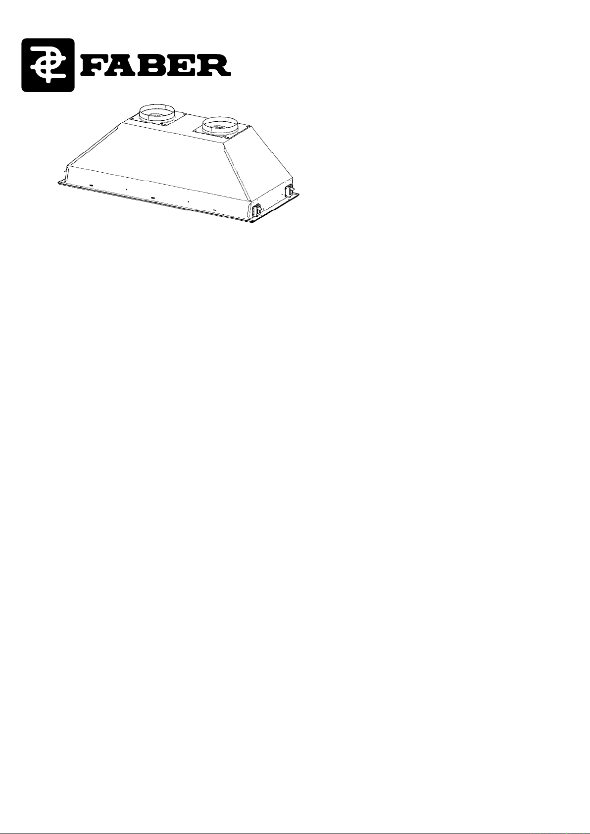
INCA PRO 38
Power Pack
• Installation Instructions
• Use and Care Information
READ AND SAVE THESE INSTRUCTIONS
The Installer must leave these instructions with the homeowner.
The homeowner must keep these instructions for future reference
and for local electrical inspectors' use.
READ THESE INSTRUCTIONS BEFORE YOU START INSTALLING THIS RANGEHOOD
WARNING: - TO REDUCE THE RISK OF A RANGE TOP GREASE FIRE: a) Never leave surface units unattended at high settings.
Boilovers cause smoking and greasy spillovers that may ignite. Heat oils slowly on low or medium setting. b) Always turn hood
ON when cooking at high heat or when ambeing food (i.e. Crepes Suzette, Cherries Jubilee, Peppercorn Beef Flambé). c) Clean
ventilating fans frequently. Grease should not be allowed to accumulate on fan or lter. d) Use proper pan size. Always use
cookware appropriate for the size of the surface element.
WARNING: - TO REDUCE THE RISK OF INJURY TO PERSONS IN THE EVENT OF A RANGE TOP GREASE FIRE, OBSERVE THE
FOLLOWING: SMOTHER FLAMES with a close-tting lid, cookie sheet, or metal tray, then turn off the burner. BE CAREFUL TO
PREVENT BURNS. If the ames do not go out immediately EVACUATE AND CALL THE FIRE DEPARTMENT. NEVER PICK UP A
FLAMING PAN - You may be burned. DO NOT USE WATER, including wet dishcloths or towels - a violent steam explosion will
result. Use an extinguisher ONLY if: 1. You know you have a Class ABC extinguisher, and you already know how to operate it. 2.
The re is small and contained in the area where it started. 3. The re department is being called. 4. You can ght the re with
your back to an exit.
ALL WALL AND FLOOR OPENINGS WHERE THE RANGEHOOD IS INSTALLED MUST BE SEALED.
This rangehood requires at least 24" of clearance between the bottom of the rangehood and the cooking surface or countertop. This minimum
clearance may be higher depending on local building code. For example, for gas ranges, a minimum of 30" may be required. The maximum
depth of overhead cabinets is 13". Overhead cabinets on both sides of this unit must be a minimum of 18" above the cooking surface or
countertop. Consult the cooktop or range installation instructions given by the manufacturer before making any cutouts. MOBILE HOME
INSTALLATION The installation of this rangehood must conform to the Manufactured Home Construction and Safety Standards, Title 24
CFR, Part 3280 (formerly Federal Standard for Mobile Home Construction and Safety, Title 24, HUD, Part 280). Four wire power supply
must be used and the appliance wiring must be revised. See Electrical Requirements.
LISEZ BIEN CETTE FICHE AVANT D'INSTALLER LA HOTTE
AVERTISSEMENT - POUR MINIMISER LE RISQUE D’UN FEU DE GRAISSE SUR LA TABLE DE CUISSON : a) Ne jamais laisser un
élément de la table de cuisson fonctionner sans surveillance à la puissance de chauffage maximale; un renversement/débordement de matière graisseuse pourrait provoquer une inammation et le génération de fumée. Utiliser toujours une puissance de
chauffage moyenne ou basse pour le chauffage d’huile. b) Veiller à toujours faire fonctionner le ventilateur de la hotte lors d’une
cuisson avec une puissance de chauffage élevée ou lors de la cuisson d’un mets à amber (i.e. Crepes Suzette, Cherries Jubilee,
Peppercorn Beef Flambé). c) Nettoyer fréquemment les ventilateurs d’extraction. Veiller à ne pas laisser de la graisse s’accumuler
sur les surfaces du ventilateur ou des ltres. d) Utiliser toujours un ustensile de taille appropriée. Utiliser toujours un ustensile
de taille adapté à la taille de l’élément chauffant.
AVERTISSEMENT: - POUR PRÉVENIR LES BLESSURES EN CAS DE FEU SUIVRE LES RECOMMANDATIONS SUIVANTES: ÉTOUFFEZ
LE FEU avec un couvercle métallique et fermez le brûleur. Si le feu ne s'éteint pas tout de suite, QUITTEZ LES LIEUX ET APPELEZ
LES POMPIERS. NE TOUCHEZ JAMAIS UNE CASSEROLE EN FLAMMES. N'UTILISEZ JAMAIS DE L'EAU ou un torchon mouillé
pour éteindre le feu - ce qui pourrait causer une explosion de vapeur. N'utilisez un extincteur que si: 1. Vous avez un modèle
ABC et vous connaissez bien son mode d'emploi. 2. Le feu est petit et peu répandu. 3. Les pompiers sont déjà prévenus. 4.
Vous avez une sortie derrière vous.
TOUTE OUVERTURE DANS LE MUR OU LE PLANCHER À PROXIMITÉ DE LA HOTTE DOIT ÊTRE SCELLÉ
Gardez 24 po. de hauteur entre le bas de la hotte et la surface de cuisson. Cette hauteur minimum peut être plus haute suivant le code
municipal. Par exemple, les cuisinières à gaz peuvent requérir 30 po. de hauteur. Les armoires au-dessus ne dépasseront pas 13 po. de
profondeur. Les armoires au-dessus de chaque côté devront être au moins à 18 po. au-dessus de la surface de cuisson. Consultez la
che technique avant de découper les armoires. L'installation de cette hotte doit être conforme aux Réglements de Manufactured Home
Construction and Safety Standards, titre 24 CFR, Section 3280 (anciennement Federal Standard for Mobile Home Construction and Safety
Standards, titre 24 CFR, Section 3280 (anciennement Federal Standard for Mobile Home Construction and Safety, titre 24, HUD, Section
280). Le branchement électrique se fait avec une raccordement à 4 ls. Consultez la che technique électrique.
Version 7/07 - Page 1
Page 2
VENTING REQUIREMENTS
!
!
Determine which venting method is best for your application.
Ductwork can extend either through the wall or the roof.
When making the electrical connection, cut a 1 1/4" hole in the
wall. A hole cut through wood must be sanded until smooth. A
hole through metal must have a grommet.
The length of the ductwork and the number of elbows should
be kept to a minimum to provide efcient performance. The
size of the ductwork should be uniform. Do not install two elbows together. Use duct tape to seal all joints in the ductwork
system. Use caulking to seal exterior wall or oor opening
around the cap.
Flexible ductwork is not recommended. Flexible ductwork
creates back pressure and air turbulence that greatly
reduces performance.
Make sure there is proper clearance within the wall or oor for
exhaust duct before making cutouts. Do not cut a joist or stud
unless absolutely necessary. If a joist or stud must be cut, then
a supporting frame must be constructed.
FOR MORE SPECIFIC DUCTWORK INFORMATION, GO
TO PAGE 6.
WARNING - To Reduce The Risk Of Fire, Use Only Metal
Ductwork.
WARNING
• Venting system MUST terminate outside the
home.
• DO NOT terminate the ductwork in an attic or
other enclosed space.
• DO NOT use 4" laundry-type wall caps.
• Flexible-type ductwork is not recommended.
• DO NOT obstruct the ow of combustion and
ventilation air.
• Failure to follow venting requirements may result
in a re.
ELECTRICAL REQUIREMENTS
WARNING - TO REDUCE THE RISK OF FIRE OR ELECTRIC
SHOCK, do not use this fan with any solid-state speed
control device.
WARNING - TO REDUCE THE RISK OF FIRE, ELECTRICAL
SHOCK, OR INJURY TO PERSONS, OBSERVE THE FOL-
LOWING: Use this unit only in the manner intended by
the manufacturer. If you have any questions, contact the
manufacturer.
Before servicing or cleaning unit, switch power off at service
panel and lock the service disconnecting means to prevent
power from being switched on accidentally. When the
service disconnecting means cannot be locked, securely
fasten a prominent warning device, such as a tag, to the
service panel.
WARNING - TO REDUCE THE RISK OF SHOCK: This fan
must be installed with an isolating wall control/switch.
CAUTION: For General Ventilating Use Only. Do Not Use To
Exhaust Hazardous or Explosive Materials and Vapors.
WARNING - TO REDUCE THE RISK OF FIRE, ELECTRICAL
SHOCK, OR INJURY TO PERSONS, OBSERVE THE FOL-
LOWING: Installation Work And Electrical Wiring Must
Be Done By Qualied Person(s) In Accordance With All
Applicable Codes And Standards, Including Fire-Rated
Construction.
Sufcient air is needed for proper combustion and exhausting of gases through the ue (chimney) of fuel burning
equipment to prevent backdrafting. Follow the heating
equipment manufacturer's guideline and safety standards
such as those published by the National Fire Protection
Association (NFPA), and the American Society for Heating,
Refrigeration and Air Conditioning Engineers (ASHRAE),
and the local code authorities.
When cutting or drilling into wall or ceiling, do not damage
electrical wiring and other hidden utilities.
A 120 volt, 60 Hz AC-only electrical supply is required on a separate 15 amp fused circuit. A time-delay fuse or circuit breaker
is recommended. The fuse must be sized per local codes in
accordance with the electrical rating of this unit as specied
on the serial/rating plate located inside the unit near the eld
wiring compartment. THIS UNIT MUST BE CONNECTED
WITH COPPER WIRE ONLY. Wire sizes must conform to the
requirements of the National Electrical Code, ANSI/NFPA 70
- latest edition, and all local codes and ordinances. Wire size
and connections must conform with the rating of the appliance.
Copies of the standard listed above may be obtained from:
National Fire Protection Association
Batterymarch Park
Quincy, Massachusetts 02269
This appliance should be connected directly to the fused
disconnect (or circuit breaker) through exible, armored or
nonmetallic sheathed copper cable. Allow some slack in the
cable so the appliance can be moved if servicing is ever necessary. A UL Listed, 1/2" conduit connector must be provided
at each end of the power supply cable (at the appliance and
at the junction box)
For residential use only.
Ducted fans must always be vented to the outdoors.
WARNING
• Electrical ground is required on this rangehood.
• If cold water pipe is interrupted by plastic,
nonmetallic gaskets or other materials, DO NOT
use for grounding.
• DO NOT ground to a gas pipe.
• DO NOT have a fuse in the neutral or grounding
circuit. A fuse in the neutral or grounding circuit
could result in electrical shock.
• Check with a qualied electrician if you are in doubt
as to whether the rangehood is properly grounded.
• DO NOT use this appliance with any solid state fan
speed control device.
• Failure to follow electrical requirements may result
in a re.
Version 7/07 - Page 2
Page 3
RÈGLEMENTS D'ÉVACUATION
!
!
Conrmer la sortie d'évacuation - soit par le mur, soit par le
toit.
AVERTISSEMENT - POUR RÉDUIRE LE RISQUE D'INCENDIE
OU DE CHOC ELECTRIQUE, ne pas utiliser ce ventilateur
en conjonction avec un dispositif de réglage de vitesse à
semi-conducteurs.
Utilisez une longueur de tuyauterie minimale avec les moindres
de coudes pour la plus grande efcacité. Le diamètre de
tuyauterie doit être uniforme. N'installez jamais 2 coudes
ensemble. Scellez bien tous les joints avec un ruban adhésif
métallique à l'intérieur et scellez bien le clapet extérieur avec
du calfeutrage.
Utilisez un tuyau d'évacuation rigide lorsque possible. Un
tuyau exible égale deux fois plus qu'un tuyau rigide, ce qui
réduit la puissance d'évacuation. Un conduit d'évacuation
exible crée une contre-pression et une turbulence de l'air
qui réduisent considérablement la performance.
Veillez à ce que l'espace pour le tuyau soit ample - ainsi on
n'aurait pas besoin de découper les supports de mur intérieur.
Si ce découpage est nécessaire, veillez bien à ce qu'un
renforcement soit mis en place.
RÈGLEMENTS D'ÉVACUATION ADDITIONELL - PAGE 10
AVERTISSEMENT - Pour Ne Pas Risquer Un Feu, Utilisez
Seulement Les Matériaux Métalliques.
AVERTISSEMENT
• Le système d'évacuation DOIT sortir à l'extérieur.
• N'ÉVACUEZ PAS le conduit soit dans une
mansarde soit dans un espace enfermé.
• N'UTILISEZ PAS un clapet de séchoir à 4 pouces.
• N'utilisez pas un conduit exible.
• N'ENCOMBREZ PAS la circulation d'air.
• Faute de suivre cet avertissement pourrait
occasionner un feu.
AVERTISSEMENT – POUR MINIMISER LES RISQUES
D’INCENDIE, CHOC ÉLECTRIQUE OU DOMMAGES
CORPORELS, OBSERVER LES PRESCRIPTIONS
SUIVANTES: Suivez les recommandations du fabricant et
entre en communication avec lui pour toute information.
Fermez le courant avant tout entretien et veillez a ce qu'il
reste fermé. Si on ne peut pas verrouiller le panneaux
du service électrique, afchez un avis de danger sur la
porte.
AVERTISSEMENT – POUR MINIMISER LE RISQUE DE CHOC
ÉLECTRIQUE: Ce ventilateur doit être installé avec un mur
d'isolement iterrupteur de commande.
AVIS: Pour L'évacuation Générale - Veillez à Ne Pas Evacuer
Des Matériaux Ou Vapeurs Explosif.
AVERTISSEMENT – POUR MINIMISER LES RISQUES
D’INCENDIE, CHOC ÉLECTRIQUE OU DOMMAGES
CORPORELS, OBSERVER LES PRESCRIPTIONS
SUIVANTES: L'installation Et Le Raccordement Electrique
Doivent Se Faire Par Un Technicien Qualié Selon Tous
Les Codes Municipaux.
An d'obtenir un rendement maximal en ce qui a trait à la
combustion ainsi qu'à l'évacuation des gaz par la conduite
de cheminée, une bonne aération est nécessaire pour
tous les appareils à combustion. Suivez les conseils et
mesures de sécurité du fournisseur tels que ceux publiés
par l'Association Nationale de la Sauvegarde contre
l'Incendie et l'Association Américaine d'Ingénieurs de
Chauffage, Frigorifaction et Air Climatisé ainsi que les
codes municipaux.
En perçant un mur veillez à ne pas perforer un autre l
électrique.
FICHE TECHNIQUE ÉLECTRIQUE
Le raccordement électrique doit se faire avec un circuit séparé
de 15 ampères fusible à 120V, 60 Hz, courant alternant. On
recommande un coupe-circuit. La taille du fusible doit se
conformer aux codes municipaux suivant la spécication
électrique sur la plaque intérieure. Le diamètre du l devra aussi
se conformer aux règlements du code national électrique, ANSI/
NFPA 70 - ainsi qu'aux règlements locaux et les spécications
de cet appareil. On peut obtenir ces informations chez:
l'Association Nationale de la Prévention du Feu
Batterymarch Park
Quincy, Massachusetts 02269
Raccordez cet appareil directement au coupe-circuit avec un l
exiblle couvert en cuivre en laissant un peu de lâchement dans
le l pour permettre le déplacement de l'appareil. Veillez a ce
qu'un contact d'un demi-pouce (1/2 po.) soit installé à chaque
bout de l (soit à l'appareil ainsi qu'à la boite à fusible).
Faites un trou de 1 1/4 po. dans le mur. S'il s'agit d'un trou en
bois - sablez-le bien, tandis qu'un trou passant par le métal
demande un bouche-trou.
Une ventilateur à évacuation extérieure doit être raccordée
à l'extérieur.
AVERTISSEMENT
• Une prise à terre est nécessaire pout cette hotte.
• N'utilisez pas un tuyau à l'eau froide pour la mise
à terre s'il est branché à un joint plastique, non-
métallique ou autre.
• NE JOIGNEZ PAS la mise à terre à conduit de gaz.
• N'INSTALLEZ PAS un fusible dans le circuit de
mise à terre - ce qui peut causer une secousse
électrique.
• Vériez avec un électricien certié à ce que la hotte
soit bien mise à terre.
• Faute de suivre ces recommandations pourrait
occasionner un feu.
Uniquement pour usage menager.
Version 7/07 - Page 3
Page 4
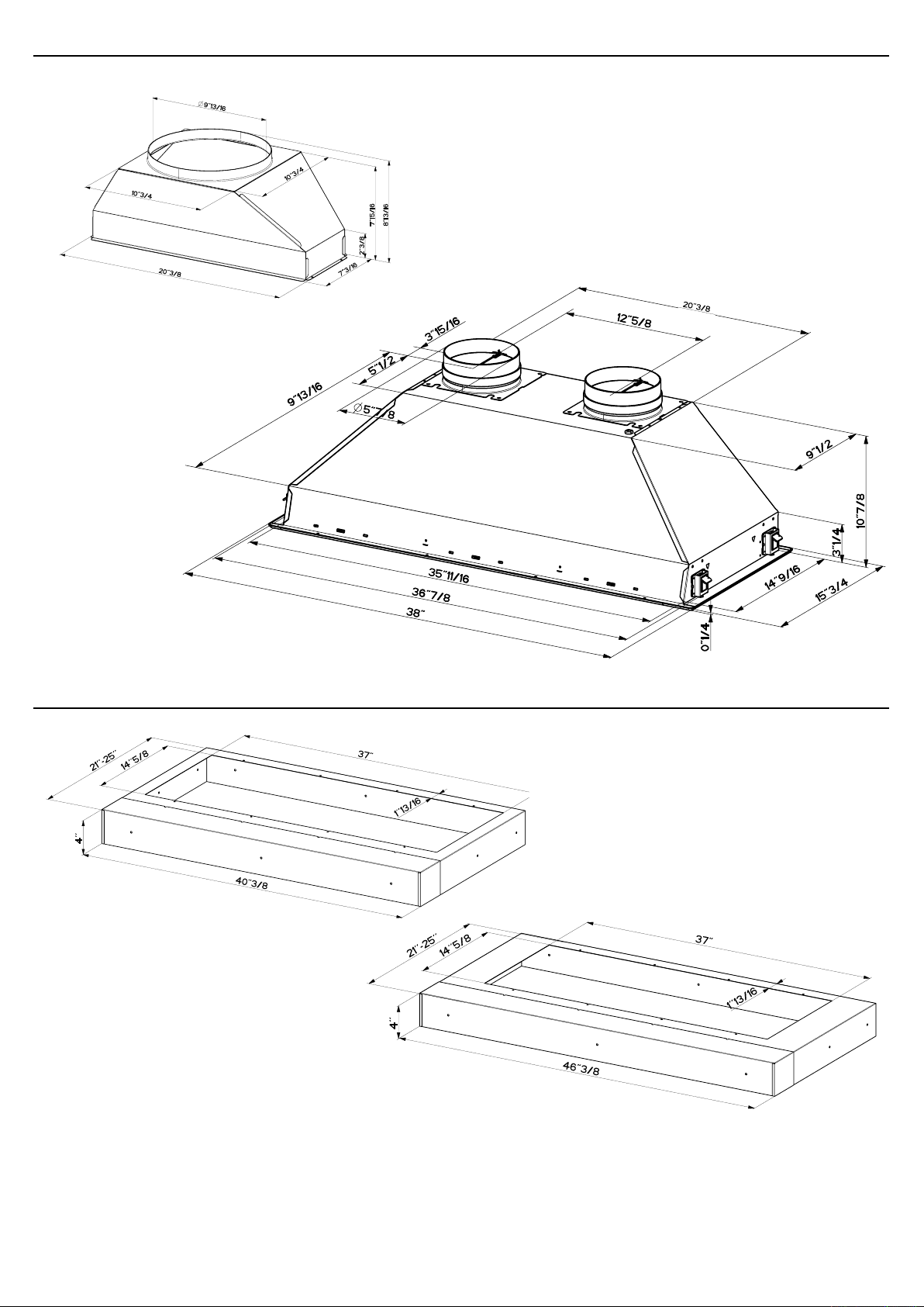
RANGEHOOD DIMENSIONS / DIMENSIONS DE LA HOTTE
OPTIONAL DUCT TRANSITION KIT
RACCORD DE TRANSITION OPTIONELLE
INCA PRO 38
LINER DIMENSIONS / DIMENSIONS DU CADRE
ProLiner 42 Stainless (620000302)
designed for 42” wide installations
Cadre Pro 42 Axier Inoxydable (620000302)
peut être employée les hottes encastrable sur mesure de 42"
ProLiner 48 Stainless (620000303)
designed for 48” wide installations
Cadre Pro 48 Axier Inoxydable (620000303)
peut être employée les hottes encastrable sur mesure de 48"
Pre-Planning Your Installation -
Important: The recommended height to install this
hood off the cooktop is a minimum of 30” for maximum effectiveness. Also consult the cooktop
manufacturer’s recommendation.
Planiez votre installation - Important : La hauteur recommandée pour installer cette hotte
au-dessus de la surface de cuisson est d’un minimum de 30” pour un maximum d’efcacité. De
plus, nous vous recommandons consulter le manuel de recommandations du fabricant de la
surface de cuisson.
Version 7/07 - Page 4
Page 5
!
TOOLS NEEDED FOR INSTALLATION
• Saber Saw or Jig Saw
• Drill
• 1 1/4" Wood Drill Bit
• Pliers
• Phillips Screwdriver
• Wire Stripper or Utility Knife
• Metal Snips
• Measuring Tape or Ruler
• Level
• Pencil
• Caulking Gun
• Duct Tape
OPTIONAL ACCESSORIES AVAILABLE
• Duct Transition Kit
optional kit, transitions two 6" round openings to one 10" round
opening
part # 620000087
• *Charcoal Filters (Order 2 Kits)
* it is highly recommended that professional style cooking always
be vented to the outside; for recirculating installations only, some
ductwork is required to exhaust the unit out of the cabinet.
part # 6093034
YOU MUST ORDER TWO OF PART #6093034 (ONE KIT FOR
EACH OF THE TWO INCA PRO MOTORS)
PARTS SUPPLIED FOR INSTALLATION
• 2 Backdraft Dampers
• 1 Literature Package
PARTS NEEDED FOR INSTALLATION
• 2 Conduit Connectors
• Power Supply Cable
• Screws to Reinforce Atttachment
• Scews for Field Wiring Box
• 1 or 2 Wall or Roof Caps
• All Metal Ductwork
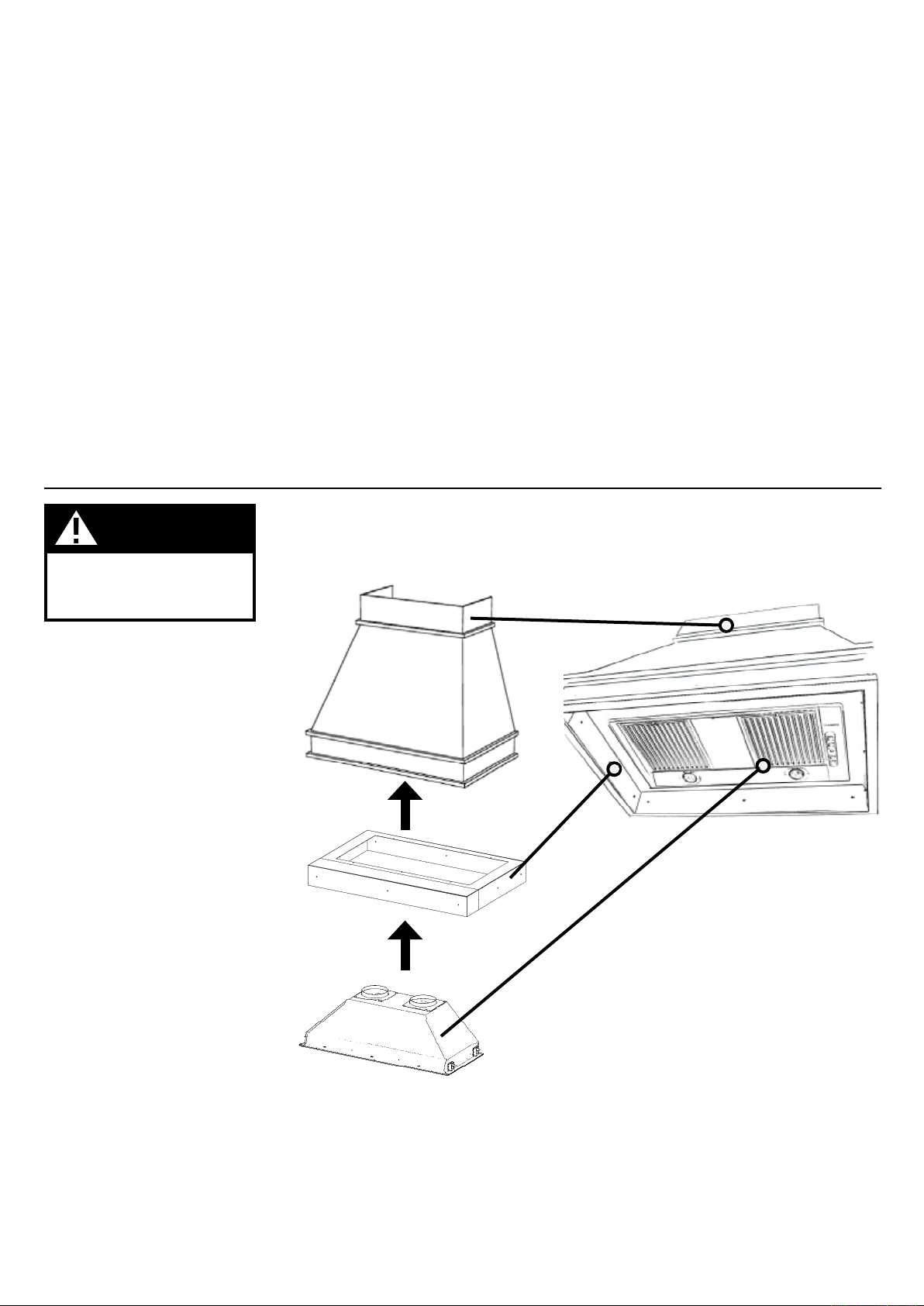
WARNING
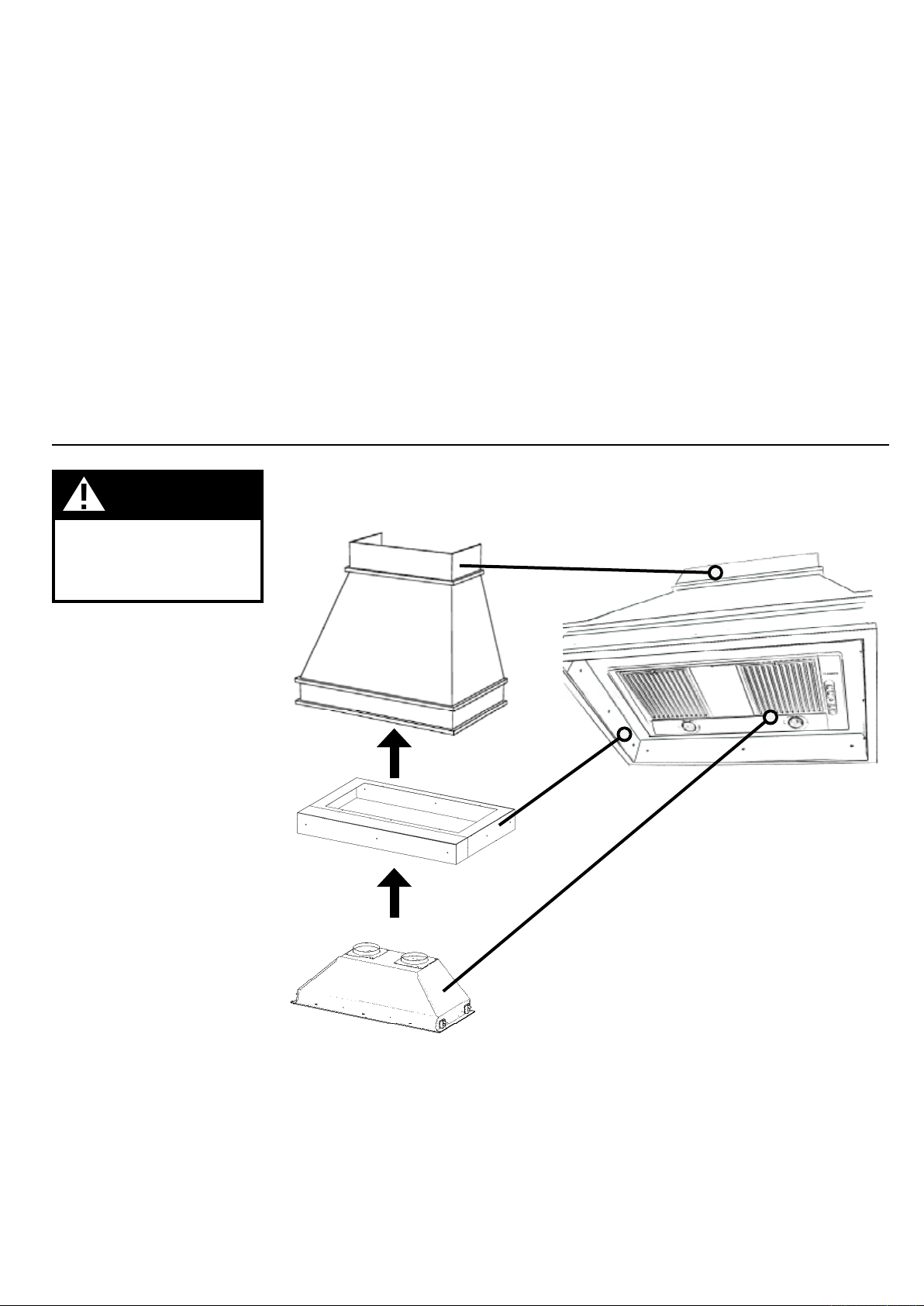
When building a custom hood,
always follow all applicable
codes and standards.
Inca Pro 38 can be used with
custom hoods 40” wide and up.
Choose either a custom liner or our
ProLiner designed for 42” and 48”
wide installations. Liners create a
perfectly-sealed, non-combustible
finish for the underside of your
custom/wood hood.
• Liners
Create a perfectly-sealed, non-combustible perimeter around the
Inca Pro 38. Depth adjustable from 21” - 25”.
ProLiner 42 Stainless - part # 620000302
ProLiner 48 Stainless - part # 620000303
FOR INSTALLATIONS WITH LINERS
CUSTOM/WOOD
HOOD
The ProLiners are made up of two
sections: a larger, rear section
(pre-cut out for insertion of the
Inca Pro 38) and a front section for
a total adjustable depth between
PRO LINER
21" and 25".
Consider the shape, size, and
weight of the Inca Pro 38 and Liner
to determine the configuration
of the custom/wood hood. See
RANGEHOOD DIMENSIONS AND
LINER DIMENSIONS on Page 4.
INCA PRO 38
1. The custom/wood hood must have a sturdy base (3/4" plywood recommended) to accomodate the cut-out for the Inca Pro 38. The
base must be recessed to accomodate the height of the Liner (see LINER DIMENSIONS on Page 4). The Liner attaches to the bottom
of the base using screws appropriate for the size and material of your custom/wood hood. The Inca Pro 38 inserts into the cut-out in the
Liner and base.
2. Position the rear section of the Liner so that it abuts the back edge of your custom/wood hood. Using a pen, trace the outline of the
pre-cut out. Remove the Liner and proceed to MAKE YOUR CUT-OUTS on Page 6. Install both sections of the Liner and proceed to
INSTALL THE RANGEHOOD on Page 7.
Version 7/07 - Page 5
Page 6
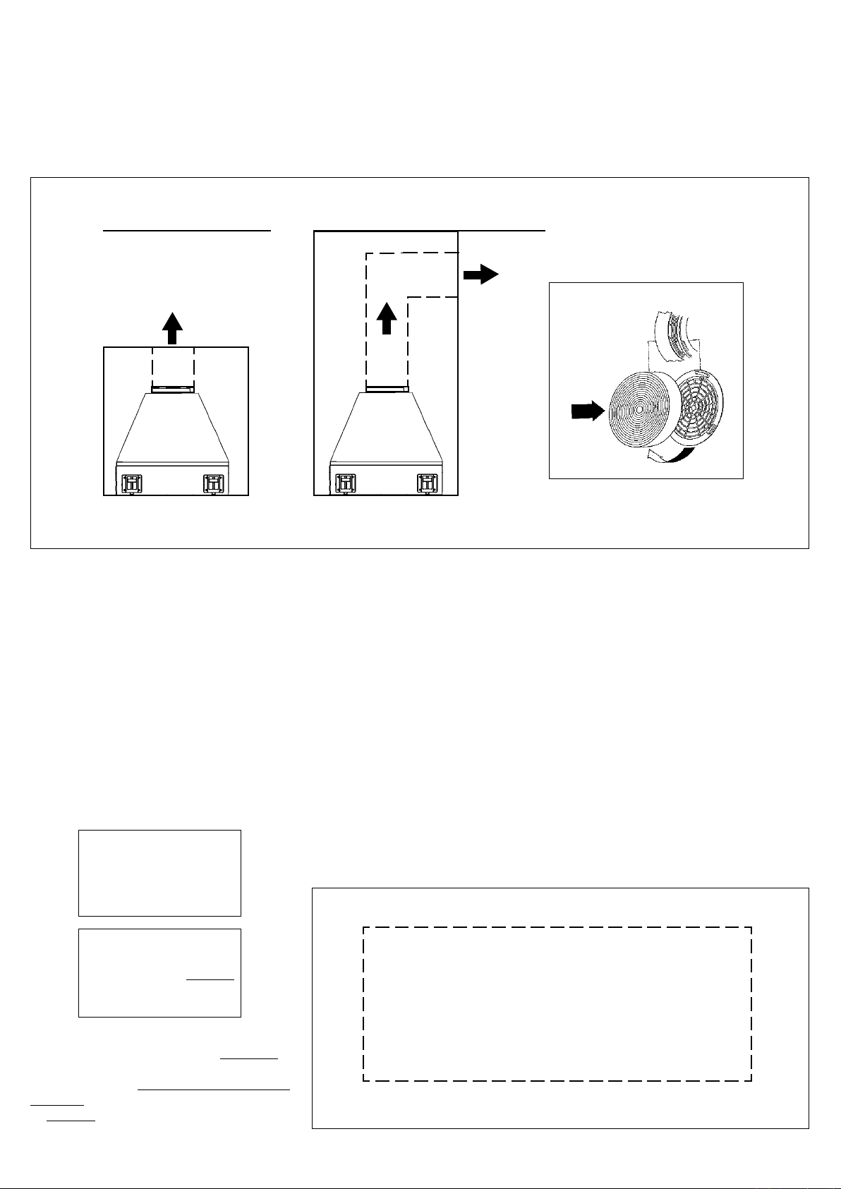
RECIRCULATING INSTALLATIONS
IT IS HIGHLY RECOMMENDED THAT PROFESSIONAL STYLE COOKING ALWAYS BE VENTED TO THE OUTSIDE. For recirculating
installations (FIGURE 1), Charcoal Filters are necessary. Remove all three grease lters and set aside. Attach one charcoal lter to each end
of both blowers. Each charcoal lter attaches to the grid on the side of the blowers. Rotate the lter clockwise to install and counterclockwise
to remove (FIGURE 1A). Replace all three grease lters. Recirculating installations also require some duct work to divert the air out of the
top or face of the cabinet or custom hood. The duct work must not terminate inside the cabinet or custom hood.
ceiling
cabinet
custom
hood
or
duct
work
inca pro 38
PLAN YOUR DUCTWORK
To ensure that the blower performs to its highest
possible capacity, ductwork should be as short
and straight as possilbe.
cabinet
or
custom
hood
duct
work
inca pro 38
FIGURE 1
ceiling
FIGURE 1A
MAKE YOUR CUT-OUTS
1. Disconnect and move freestanding range from cabinet opening to provide easier access
to upper cabinet or custom hood. Put a thick, protective covering over cooktop, set-in range
or countertop to protect from damage or dirt.
The ductrun should not exceed 35 equivalent
feet if ducted using two separate duct runs of
the required minimum of 6" round duct or 55
equivalent feet if ducted with one single 10"
round duct (when using optional Duct Transi-
tion Kit). Calculate the length of the ductwork
by adding the equivalent feet in FIGURE 2 for
each piece of duct in the system An example
is given in FIGURE 3.
45˚ Elbow
90˚ Elbow
90˚ Flat Elbow
Wall Cap
FIGURE 2
9 Feet Straight Duct
2 - 90˚ Elbows
Wall Cap
Total System
FIGURE 3
3.0 feet
5.0 feet
12.0 feet
0.0 feet
9.0 feet
10.0 feet
0.0 feet
19.0 feet
For best results, use no more than three 90°
elbows. Make sure that there is a minimum of
24" of straight duct between elbows if more
than one is used. Do not install two elbows
together. If you must elbow right away, do it
as far away from the hood's exhaust opening
as possible.
2. Determine and clearly mark with a pencil the center line on the cabinet or custom hood
where the rangehood will be installed.
3. Determine and make all necessary cuts in the wall and/or ceiling for the ductwork. Install
the ductwork before the rangehood.
4. Determine the proper location for the Power Supply Cable. Use a 1 1/4" Drill Bit to make
this hole. Install the cable. Use caulking to seal around the hole. DO NOT turn on the
power until installation is complete.
5. Make the cut-out opening where the rangehood will be installed (FIGURE 4).
37"
14 5/8"
CUT-OUT
FIGURE 4
Version 7/07 - Page 6
Page 7
X X
X X
X X
F
G
G
G
G
D
X X
E
A
C
C
B
INSTALL THE RANGEHOOD
1. Remove the rangehood from the carton and place on a at sur-
face. Cover the surface to prevent accidental damage. Remove all
parts including the backdraft dampers and literature package before
discarding the carton.
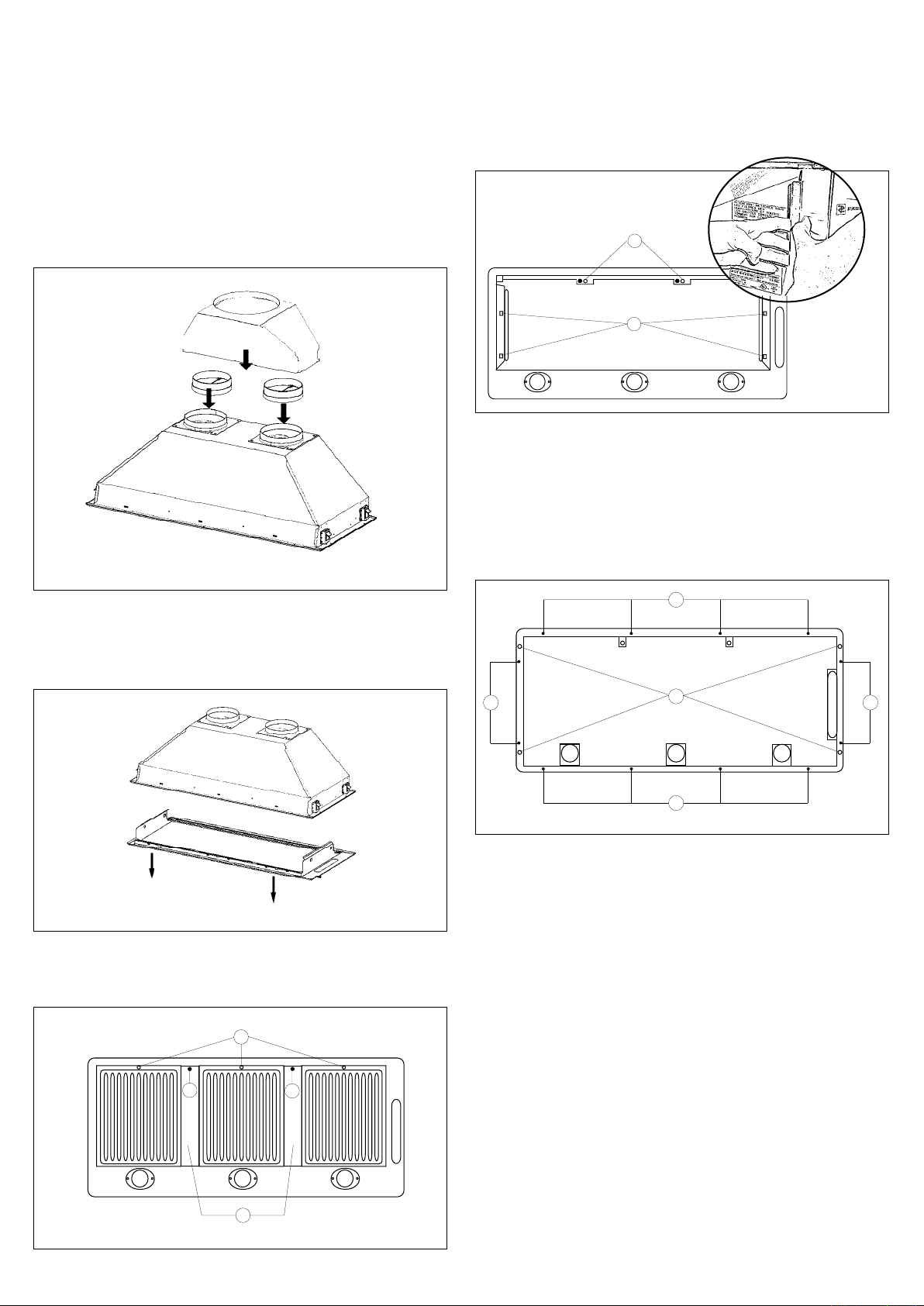
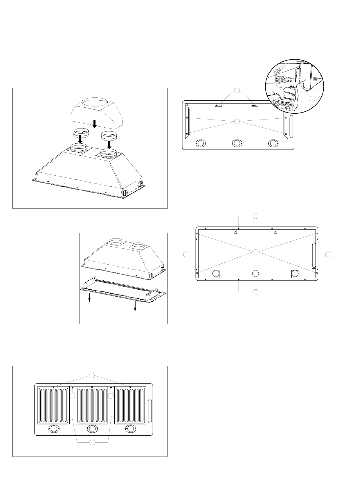
2. Place the round dampers into the exhaust openings of the rangehood and press down as indicated in FIGURE 5. If using optional
Duct Transition Kit, t this over the two round dampers and screw
onto the top of the unit (screws not provided). Use duct tape to secure
if necessary.
FIGURE 5
5. Remove the two philips screws (D in FIGURE 8). Remove the entire
bottom of the rangehood by pushing your thumb into the side holes
(E in FIGURE 8) and pulling the sides free from the rangehood.
FIGURE 8
6. Fix the rangehood to the cabinet or custom hood using the four
spring loaded brackets, two on each side of the rangehood. Using
a philips screwdriver or drill, tighten the adjustment screws (F in
FIGURE 9) until the brackets adhere tightly to the surface.
7. IMPORTANT: There are 12 holes (G in FIGURE 9) for screws
(not provided) to reinforce the rangehood to your cabinet or custom
hood. Use screws appropriate for the size and type of materials of
your cabinet or custom hood.
3. The entire bottom of the rangehood must be removed for installation
as indicated in FIGURE 6. Remove the grease lters USING TWO
HANDS (one to hold the lter so that it doesn't fall on cooktop and
one to turn the knob (A in FIGURE 7) by pulling the knob out and
turning to the left.
FIGURE 6
4. Remove the grease lter dividers (B in FIGURE 7) by rst removing
the plastic screw cover (C in FIGURE 7), then removing the phillips
screw under the screw cover.
FIGURE 7
FIGURE 9
8. Replace the bottom of the rangehood and reinsert the grease lter
dividers and grease lters.
9. Remove the cover from the eld wiring compartment with a phillips
screwdriver. Feed the Power Supply Cable through the electrical
knockout. Connect the Power Supply Cable to the rangehood cable.
Attach the White lead of the power supply to the White lead of the
rangehood with a twist-on type wire connector. Attach the Black lead
of the power supply to the Black lead of the rangehood with a twist-on
type wire connector. Attach the Power Supply Cable grounding lead to
the green screw provided. Using the 4 holes provided screw the eld
wiring compartment to the wall or cabinet as dictated by your Power
Supply Cable location (screws not provided). Replace the cover.
10. Connect the ductwork to the dampers or Duct Transition Kit and
seal all connections with duct tape.
11. Turn the power supply on. Turn on the blower and light. If the
rangehood does not operate, check that the circuit breaker is not
tripped or the house fuse blown. If the unit still does not operate,
disconnect the power supply and check that the wiring connections
have been made properly.
Version 7/07 - Page 7
Page 8
A
USE AND CARE INFORMATION
0 1 0 1 0 1 2
LM V
This rangehood system is designed to remove smoke, cooking vapors
and odors from the cooktop area.
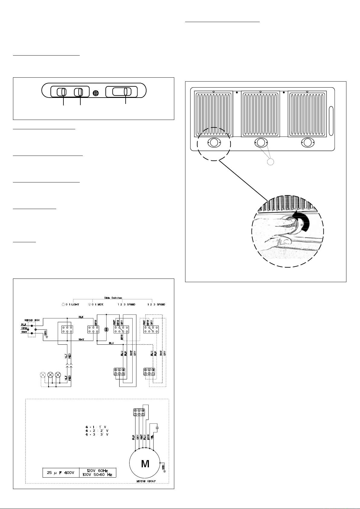
Rangehood Control Panel
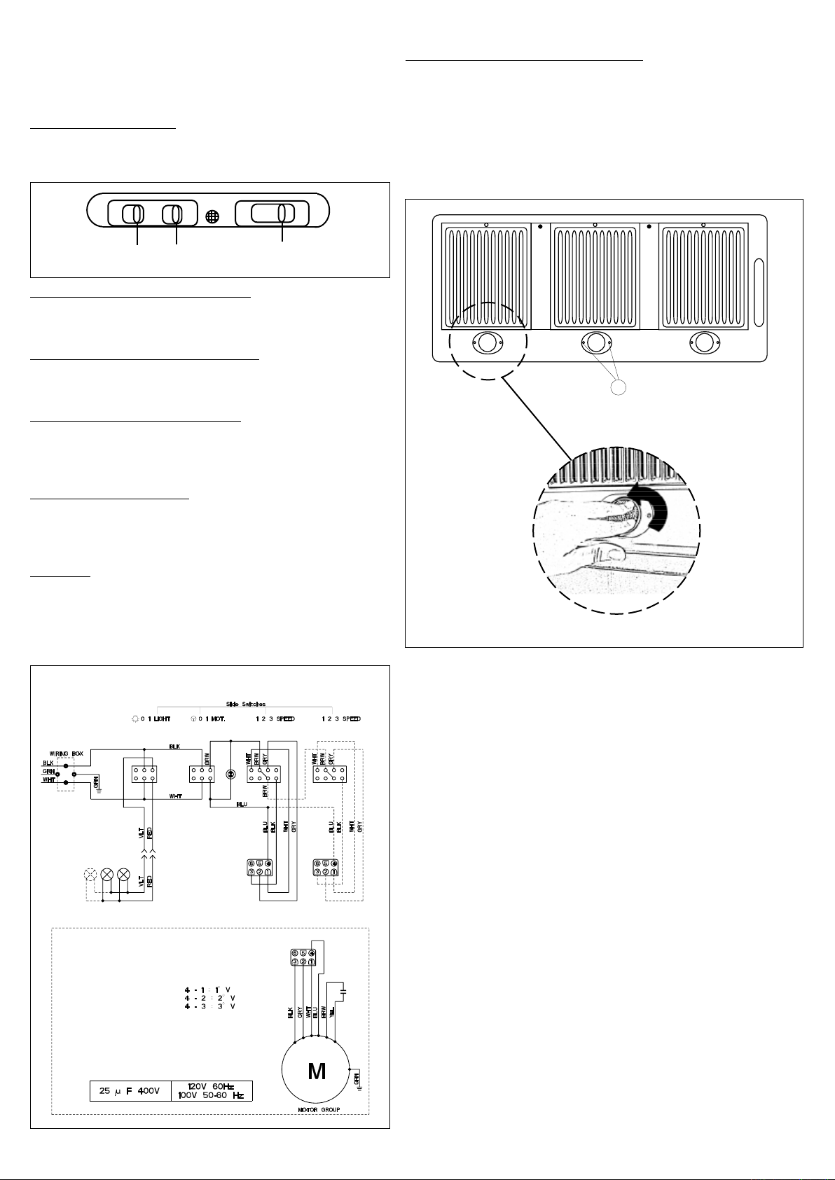
The control panel is located on the right-hand side under the canopy.
The position and function of each control button are indicated in
FIGURE 10.
FIGURE 10
Light On/Off Button ( L )
On/Off switch for the halogen lights. Move the switch to "1" to turn
the light ON and to "0" to turn it OFF.
Blower On/Off Button ( M )
On/Off switch for the blower. Move the switch to "1" to turn the
blower ON and to "0" to turn it OFF.
Blower Speed Button ( V )
Speed control for blower. Move the switch to position 1 for LOW
Speed, 2 for MEDIUM speed and 3 for HIGH speed.
Replacing the Halogen Lamp
Before you begin, make sure that the rangehood is turned off and
that the other lamps have had sufcient time to cool. Halogen lamps
burn extremely hot and serious injury could result from touching a
hot lamp. Press and twist the lamp to remove. If this is difcult for
you, you can remove the stainless bezel which is held in place by two
screws (A in FIGURE 11). Remove the two screws and the bezel.
Then remove the lamp and replace with a new lamp. Once the new
lamp is in place, reinstall the bezel.
For Best Results
Start the rangehood several minutes before cooking to develop proper
airow. Allow the unit to operate for several minutes after cooking is
complete to clear all smoke and odors from the kitchen.
Cleaning
The stainless steel grease lters should be cleaned frequently in hot
detergent solution or washed in the dishwasher. Clean exterior surfaces with a commercially available stainless steel cleaner. Abrasives
and scouring agents can scratch stainless steel nishes and should
not be used to clean nished surfaces.
WIRING DIAGRAM
FIGURE 11
WARRANTY & SERVICE
All Faber products are warranteed against any defect in materials or
workmanship for the original purchaser for a period of 1 year from the
date of original purchase. This warranty covers labor and replacement
parts. The warranty does not cover consumable parts such as lters
and light bulbs. This warranty does not apply if this product has been
subjected to faulty installation, misuse, or neglect. This warranty
excludes any consequential expense or damage resulting from any
use or malfunction of the product. All implied warranties are limited
to the duration of this warranty.
To obtain warranty service, contact the dealer from whom you
purchased the rangehood, or the local Faber distributor. If you cannot
identify a local Faber distributor, contact us at (508) 358-5353 for the
name of a distributor in your area.
• This rangehood uses 45 watt Halogen Lamps.
Version 7/07 - Page 8
Page 9
OUTILS NÉCESSAIRES À L’INSTALLATION
!
• Scie sauteuse ou à découper
• Perceuse
• Mèche à bois 1 1/4 po
• Pinces
• Tournevis Phillips
• Dénude l ou couteau tout usage
• Pince coupante à l métallique
• Ruban à mesurer ou règle
• Niveau
• Crayon
• Outil à calfeutrage
• Ruban à conduit
PIÈCES NÉCESSAIRES POUR L’INSTALLATION
• 2 connecteurs de conduit
• Câble d’alimentation
• 1 ou 2 capuchon de mur ou de toit
• Conduit en métal
• Vis pout réinforcement
• Vis pour compartiment de lage
ACCESSOIRES POUR L’INSTALLATION
• Raccord de Transition
De deux conduits de rond de 6 po à un conduit
rond de 10 po
part # 620000087
PIÈCES FOURNIES POUR L’INSTALLATION
• 2 registres à clapet
• 1 nécessaire de documentation
AVERTISSEMENT
En constuisant une hotte
encastrable sur commande,
suivez toujours tous les codes
et normes applicables.
L’Inca Pro 38 peut être installée
avec les hottes faites sur mesure
40” ou plus.
Pour des hottes encastrable,
choisissez un recouvrement fait
sur commande ou notre Cadre Pro
conçu pour 42” et 48” installations.
Les Cadres créent une finition
parfait-scellée et non-combustible
pour le dessous de votre hotte
encastrable.
• Filtres au Charbon
Pour installation sans conduit
part # 6093034 (Acheter deux 6093034)
• Cadres
21" - 25" prof. ajustable
Cadre Pro 42 - part # 620000302
Cadre Pro 48 - part # 620000303
INSTALLATIONS AVEC CADRES
HOTTE
ENCASTRABLE
CADRE PRO
Les Cadres Pro se composent de
deux sections: une plus grande,
arrière section et une section avant
pour une profondeur réglable totale
entre 21” et 25".
Considérez la forme, la taille, et
le poids de l’Inca Pro 38 et du
Cadre déterminer la conguration
INCA PRO 38
de la hotte encastrable. Voir des
DIMENSIONS DE LA HOTTE ET
DIMENSIONS DU CADRE à la
page 4.
1. La hotte encastrable doit avoir une base vigoureuse (3/4” contre-plaqué recommandé) pour adapter au coupe-circuit pour l’Inca Pro
38. La base doit être enfoncée pour adapter à la taille du Cadre (voir les DIMENSIONS DU CADRE à la page 4). Les attaches de Cadre
au fond de la base à l’aide des vis appropriées pour la hotte encastrable. L’Inca Pro 38 est installé dans le coupe-circuit dans le Cadre
et la base.
2. Placez la section arrière du Cadre de sorte qu’il aboute le bord arrière de votre hotte encastrable. En utilisant un stylo, tracez le contour
de la sortie précoupée. Enlevez le Cadre et procédez FAIRE LA COUPE à la page 10. Installez les deux sections du Cadre et procédez
INSTALLATION DE LA HOTTE à la page 11.
Version 7/07 - Page 9
Page 10

INSTALLATION POUR RECIRCULATION D'AIR
Un nécessaire des deux Filtres au Charbon (FIGURE 1A) est requis pour ce type d'installation. Installation pour recirculaton d'air requis
conduit pour divertir l'air à l'extérieur de l'armoire. Ne la conduit terminez pas dan l'armoire.
le plafond
encastrable
hotte
encastrable
conduit
inca pro 38
FIGURE 1 - INSTALLATION POUR RECIRCULATION D'AIR
PLAN DU CONDUIT
Pour assurer que le ventilateur marche le mieux,
le conduit doit être aussi court et aussi droit que
possible.
La longueur du conduit ne doit jamais excéder 35 pi
s’il s’agit de conduit rond de 6 po et 55 pi équivalents
avec conduit rond de 10 po (avec Raccord de
Transition). Calculer la longueur du conduit en
ajoutant l’équivalent en pied de la FIGURE 2 pour
chaque pièce du conduit du système. Un exemple
est donné à la FIGURE 3.
45˚ Elbow
90˚ Elbow
90˚ Flat Elbow
Wall Cap
FIGURE 2
9 Feet Straight Duct
2 - 90˚ Elbows
Wall Cap
Total System
FIGURE 3
3.0 feet
5.0 feet
12.0 feet
0.0 feet
9.0 feet
10.0 feet
0.0 feet
19.0 feet
hotte
conduit
inca pro 38
le plafond
FIGURE 1A
FAIRE LA COUPE
1. Débrancher et enlever la cuisinière an d’avoir un meilleur accès aux armoires su-
périeures et au mur arrière. Placer un recouvrement épais sur la plaque de cuisson, la
cuisinière encastrée ou le dessus du comptoir pour protéger des dommages et de la
poussière.
2. Déterminer et marquer clairement, à l’aide d’un crayon, la ligne centrale sur le mur où
la hotte sera installée.
3. Déterminer et faire toutes les coupes nécessaires dans le mur ou le plafond pour les
conduits. Installer les conduits avant la hotte.
4. Déterminer l’emplacement approprié pour le câble d’alimentation. Utiliser une mèche
de 1 1/4 po pour faire un trou et y passer le câble d’alimentation. Utiliser du calfeutrage
pour sceller tout autour du trou. NE PAS mettre en circuit tant que l’installation n’est pas
complétée.
5. Découper l'ouverture où la hotte sera installée (FIGURE 4).
37"
14 5/8"
CUT-OUT
Pour de meilleurs résultats, ne pas utiliser plus
de trois coudes de 90˚. S’assurer qu’il y ait un
minimum de 24 po de conduit droit entre les
coudes si l’on utilise plus d’un coude. Ne pas
installer deux coudes ensemble.
FIGURE 4
Version 7/07 - Page 10
Page 11
D
X X
E
INSTALLATION DE LA HOTTE
A
C
C
B
X X
X X
X X
F
G
G
G
G
1. Retirer l’appareil de la boîte et le déposer sur une surface plate pour
l’assemblage. Couvrir la surface pour éviter tout dommage. Retirer toutes
les pièces incluant les vis, les registre à clapets et le nécessaire de
documentation avant de jeter la boîte.
2. Placer les registres rond dans les ouvertures d'échappement de la
hotte et appuyer fortement sur le registre (de la FIGURE 5). Si utilisez
le Raccord de Transition, installer au dessus de les registres rond.
FIGURE 5
5. Retirer les deux vis (D in FIGURE 8). Retirer le bas de la hotte
par plasser votre pouce dans les trous (E in FIGURE 8) et tirer le
bas de la hotte.
FIGURE 8
6. Installer la hotte sur l’armoire à l’aide de quatre xations à res-
sort, deux de chaque côté de la hotte. Utiliser un tournevis Phillips
et serrer la vis de reglement (F de la FIGURE 9) tandis que les
xations s'attachent fortement à la surface.
7. IMPORTANT: Installer la hotte sur l’armoire à l’aide des 12 vis (ne
pas fournies) dans les trous (G de la FIGURE 9).
3. Retirer le bas de la hotte
(FIGURE 6). Retirer les ltres
pour la graisse de l’appareil
et mettre de côté. Lors de la
dépose des ltres, tirer/faire
tourner le bouton avec une
main, et tenir le ltre avec
l'autre main pour qu'il ne
tombe pas sur la table de
cuisson. Tirer le bouton (A
de la FIGURE7) vers l'avant
de la hotte en le tournant vers
la guache (sens antihoraire)
pour débloquer le levier de
FIGURE 6
verrouillage.
4. Retirer les séparations de les ltres pour la graisse (B de la FIGURE 7). Retirer le couvercle plastique pour le vis (C de la FIGURE
7); retirer le vis.
FIGURE 7
FIGURE 9
8. Replacer le bas de la hotte et les séparations de les ltres pour la
graisse, et les ltres pour la graisse
9. Retirer le couvercle du compartiment de lage. Passer le câble
d’alimentation dans la pastille enfonçable. Attacher le l blanc du
câble d’alimentation sur le l blanc de la hotte avec une cosse.
Attacher le l noir du câble d’alimentation au l noir de la hotte avec
une cosse. Brancher le l de mise à la terre vert (jaune et vert) sous
la vis de mise à la terre verte. Utiliser les quatre trous fournis et
xer le compartiment de lage au mur ou à l'armoire, déterminé par
l'emplacement du câble d’alimentation (vis non fournies). Replacer
le couvercle.
10. Brancher le conduit sur les registres ou la Raccord de Transition
et sceller toutes les connexions avec du ruban à conduit.
11. Mettre l’alimentation en circuit. Mettre en circuit le ventilateur et la
lumière. Si la hotte ne fonctionne pas, vérier si le disjoncteur n’est
pas fermé ou si le fusible n’est pas grillé. Si l’appareil ne fonctionne
toujours pas, débrancher l’alimentation et vérier si les connexions
ont été effectuées correctement.
Version 7/07 - Page 11
Page 12
0 1 0 1 0 1 2
LM V
A
UTILISATION ET ENTRETIEN
Cette hotte est conçue pour enlever la fumée, les vapeurs de cuisson
et les odeurs de la cuisine.
Panneau de commandes
Le panneau de commandes est situé sur le côté droit sous la hotte.
La position et la fonction de chaque bouton dont indiquées à la
FIGURE 10.
FIGURE 10
Bouton marche-arrêt de la lumière (L)
Interrupteur marche-arrêt pour la lumière. Régler à « 1 » pour mettre
en circuit (ON) ou à « 0 » pour mettre hors circuit (OFF).
Bouton marche-arrêt du ventilateur (M)
Interrupteur marche-arrêt pour le ventilateur. Régler à « 1 » pour
mettre en circuit (ON) ou à « 0 » pour mettre hors circuit (OFF).
Bouton de vitesse du ventilateur (V)
Réglage de la vitesse. Régler à « 1 » pour vitesse basse (LOW),
à « 2 » pour vitesse moyenne (MEDIUM) et à « 3 » pour vitesse
élevée (HIGH).
Remplacement de la lumière halogène
Avant de commencer, s’assurer que la hotte est hors circuit et que
les autres ampoules ne sont pas chaudes. Les ampoules halogènes
sont extrêmement chaudes lorsqu’elles sont allumées et tout contact
peut causer des blessures graves. Pour remplacer l’ampoule, la
bague autour de l’ampoule doit être retirée. La bague est xée par
deux vis (A de la FIGURE 11). Retirer les deux vis et la bague, puis
retirer l’ampoule et la remplacer par une nouvelle ampoule. Dès que
l’ampoule est en place, replacer la bague.
Pour de meilleurs résultats
Mettre la hotte en circuit avant de commencer la cuisson. Laisser
l’appareil fonctionner quelques minutes après la cuisson pour éliminer
la fumée et les odeurs.
Nettoyage
Nettoyer régulièrement les ltres métalliques pour la graisse avec une
solution d’eau chaude et de détergent ou mettre au lave-vaisselle.
Nettoyer les surfaces extérieures avec un détergent pour l’acier
inoxydable. Ne pas employer de produits abrasifs ou de poudre à
récurer qui endommagent les surfaces en acier inoxydable.
DIAGRAMME DE CÂBLAGE
FIGURE 11
GARANTIE ET SERVICE
Faber garantit à l’utilisateur-acheteur d’origine que les produits Faber
vendus neufs par nous sont sans vice de matériel et de main-d’oeuvre
d’origine pour une période d’un an à partir de la date d’achat. La garantie
couvre la main-d’oeuvre et les pièces de remplacement. Par contre, elle
ne couvre pas les pièces reliées à l’usure normale de l’appareil (exemple:
les ltres et les ampoules). La garantie ne s’applique pas si le produit
a été mal installé, utilisé d’une manière inadéquate ou négligé. Cette
garantie exclue toutes les dépenses consécutives dûes à des dommages
résultant d’un mauvais fonctionnement du produit. La présente garantie
remplace toutes autres garanties et déclarations expresses.
An d’obtenir un service sous garantie, communiquer avec le marchand
où la hotte a été achetée ou le distributeur Faber de la région. Si l’on
ne peut trouver de distributeur Faber, communiquer avec nous au (508)
358-5353 an d’obtenir le nom d’un distributeur dans la région.
•Cette hotte utilise des ampoules halogènes de 45 W.
Version 7/07 - Page 12
 Loading...