

Page 1
Instructions Manual
Руководство по эксплуатации
Naudojimosi instrukcija
Instrukcijas Grāmata
Kasutusjuhend
ﺐﻴآﺮﺘﻟا ﻞﻴﻟ
د
Page 2

2
2
INDEX
RECOMMENDATIONS AND SUGGESTIONS ..................................................................................................................... 3
CHARACTERISTICS ............................................................................................................................................................. 6
INSTALLATION...................................................................................................................................................................... 8
USE ...................................................................................................................................................................................... 11
MAINTENANCE................................................................................................................................................................... 12
УКАЗАТЕЛЬ
СОВЕТЫ И РЕКОМЕНДАЦИИ .......................................................................................................................................... 14
ХАРАКТЕРИСТИКИ............................................................................................................................................................ 17
УСТАНОВКА........................................................................................................................................................................ 19
ЭКСПЛУАТАЦИЯ................................................................................................................................................................ 22
УХОД.................................................................................................................................................................................... 23
TURINYS
PATARIMAI IR NUORODOS............................................................................................................................................... 25
PRIETAISO APRAŠYMAS .................................................................................................................................................. 28
MONTAVIMAS..................................................................................................................................................................... 30
NAUDOJIMAS...................................................................................................................................................................... 33
VALYMAS IR PRIEŽIŪRA ................................................................................................................................................... 34
INDEKSS
IETEIKUMI UN PRIEKŠLIKUMI........................................................................................................................................... 36
TEHNISKIE DATI................................................................................................................................................................. 39
UZSTĀDĪŠANA.................................................................................................................................................................... 41
IZMANTOŠANA ................................................................................................................................................................... 44
APKOPE............................................................................................................................................................................... 45
INDEKS
SOOVITUSED JA ETTEPANEKUD..................................................................................................................................... 47
OMADUSED......................................................................................................................................................................... 50
PAIGALDAMINE .................................................................................................................................................................. 52
KASUTAMINE...................................................................................................................................................................... 55
HOOLDUS............................................................................................................................................................................ 56
سﺮﻬﻔﻟا
تﺎﺣاﺮﺘﻗا و تادﺎﺷرا..............................................................................................................................................58
ﺺﺋﺎﺼﺨﻟا........................................................................................................................................................... 61
ﺐﻴآﺮﺘﻟا.............................................................................................................................................................63
ماﺪﺨﺘﺳﻻا............................................................................................................................................................. 66
ﺔﻧﺎﻴﺼﻟا ﺔﻴﻠﻤﻋ....................................................................................................................................................67
EN
RU
LT
LV
EE
SA
Page 3
EN
3
3
RECOMMENDATIONS AND SUGGESTIONS
The Instructions for Use apply to several versions of this appliance.
Accordingly, you may find descriptions of individual features that do not
apply to your specific appliance.
INSTALLATION
• The manufacturer will not be held liable for any damages resulting from
incorrect or improper installation.
• The minimum safety distance between the cooker top and the extractor hood
is 650 mm (some models can be installed at a lower height, please refer to
the paragraphs on working dimensions and installation).
• Check that the mains voltage corresponds to that indicated on the rating
plate fixed to the inside of the hood.
• For Class I appliances, check that the domestic power supply guarantees
adequate earthing.
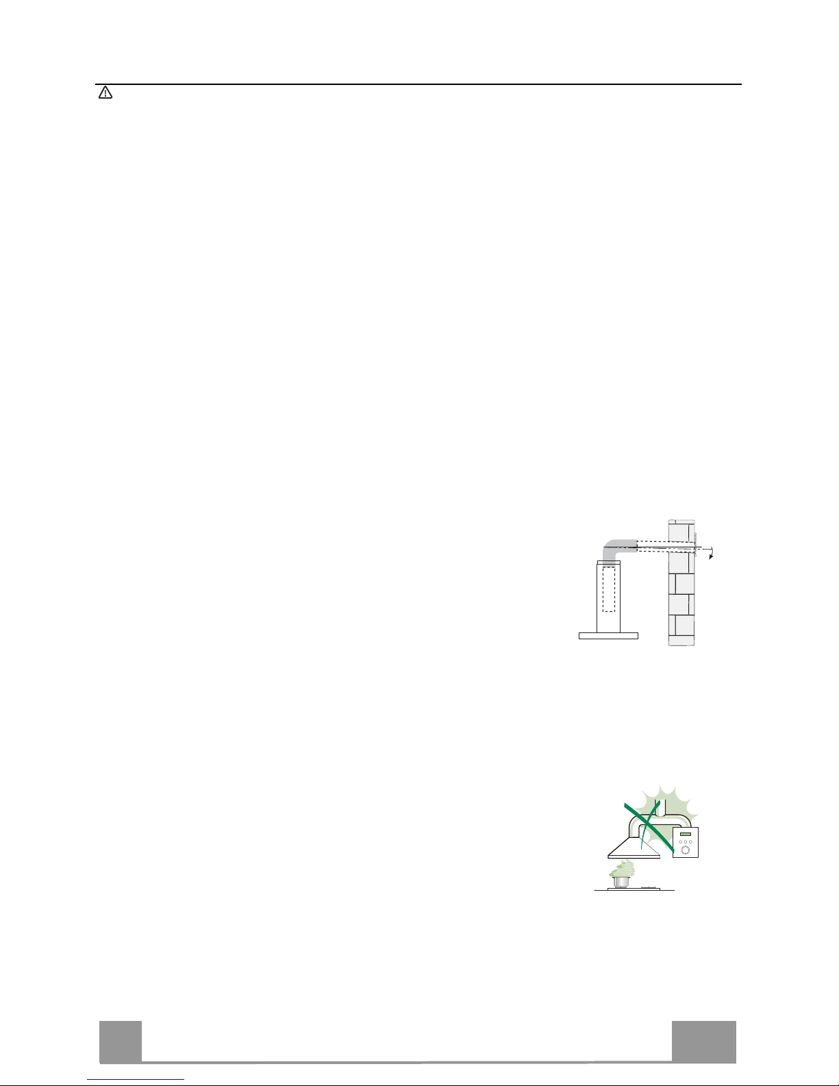
Connect the extractor to the exhaust flue through a pipe of minimum
diameter 120 mm. The route of the flue must be as short as possible.
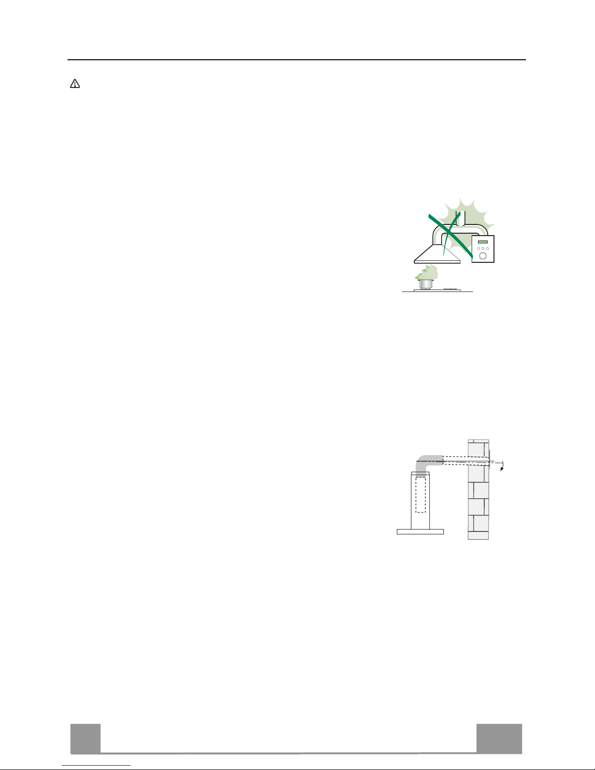
• Do not connect the extractor hood to exhaust ducts
carrying combustion fumes (boilers, fireplaces, etc.).
• If the extractor is used in conjunction with non-electrical
appliances (e.g. gas burning appliances), a sufficient
degree of aeration must be guaranteed in the room in
order to prevent the backflow of exhaust gas. The
kitchen must have an opening communicating directly
with the open air in order to guarantee the entry of clean air. When the
cooker hood is used in conjunction with appliances supplied with energy
other than electric, the negative pressure in the room must not exceed 0,04
mbar to prevent fumes being drawn back into the room by the cooker hood.
• The air must not be discharged into a flue that is used for
exhausting fumes from appliances burning gas or other
fuels (not applicable to appliances that only discharge the
air back into the room).
• In the event of damage to the power cable, it must be
replaced by the manufacturer or by the technical service
department, in order to prevent any risks.
2°
Page 4
EN
4
4
• If the instructions for installation for the gas hob specify a greater distance
specified above, this has to be taken into account. Regulations concerning
the discharge of air have to be fulfilled.
• Use only screws and small parts in support of the hood.
Warning: Failure to install the screws or fixing device in accordance with
these instructions may result in electrical hazards.
• Connect the hood to the mains through a two-pole switch having a contact
gap of at least 3 mm.
USE
• The extractor hood has been designed exclusively for domestic use to
eliminate kitchen smells.
• Never use the hood for purposes other than for which it has been designed.
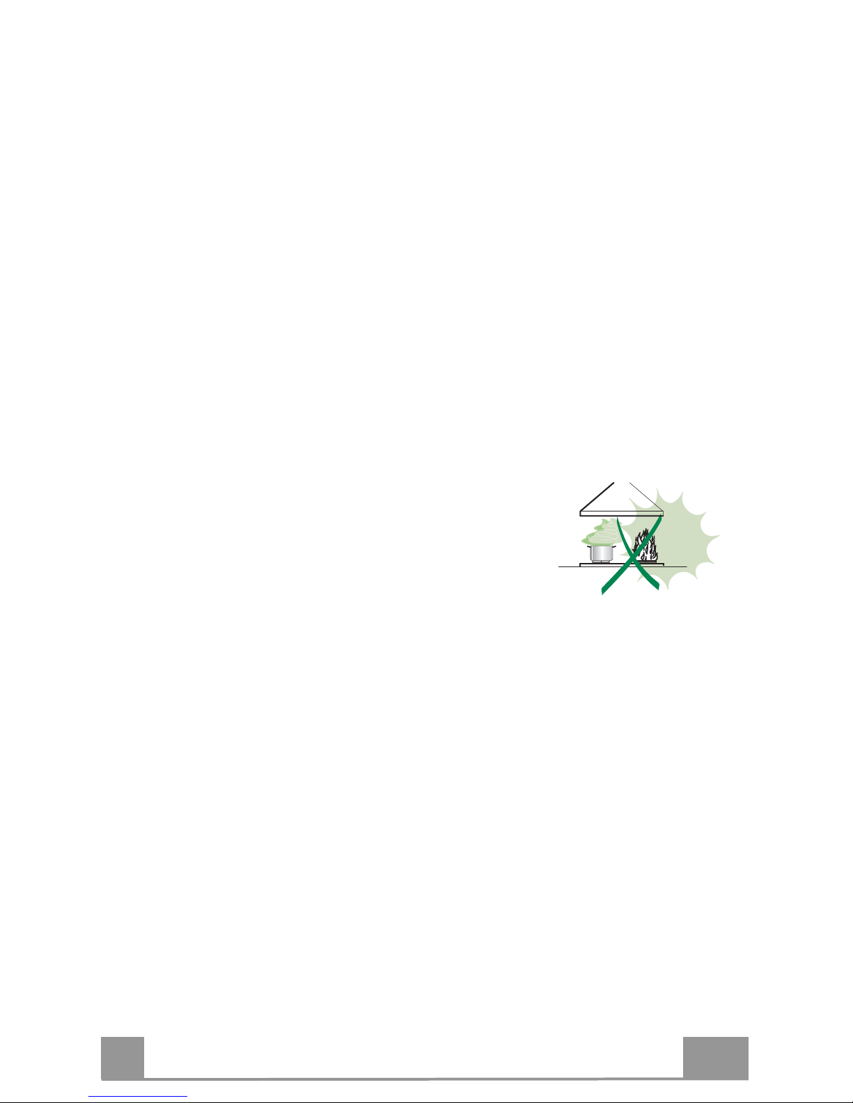
• Never leave high naked flames under the hood when it is in operation.
• Adjust the flame intensity to direct it onto the bottom of the pan only, making
sure that it does not engulf the sides.
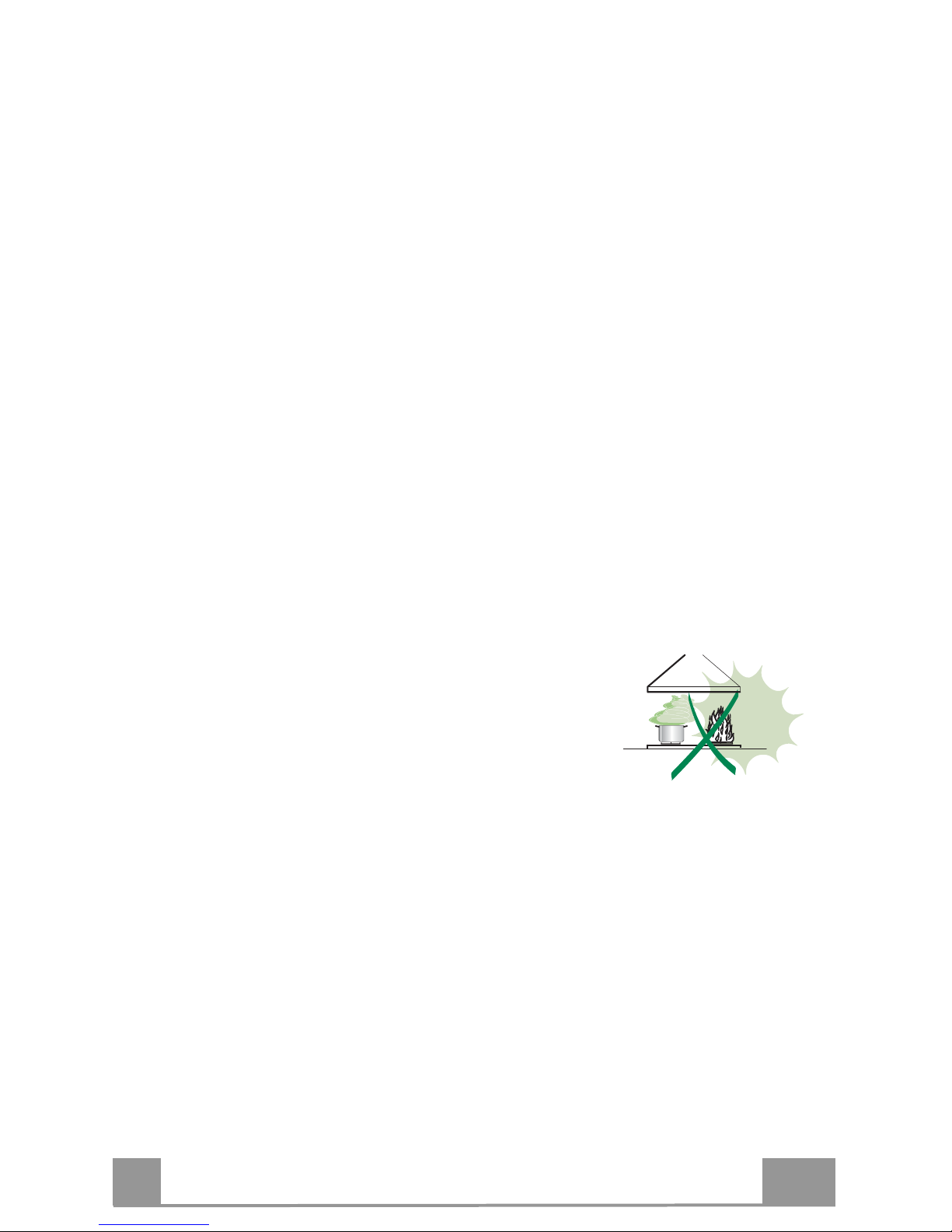
• Deep fat fryers must be continuously monitored
during use: overheated oil can burst into flames.
• Do not flambè under the range hood; risk of fire.
• This appliance can be used by children aged from
8 years and above and persons with reduced
physical, sensory or mental capabilities or lack of
experience and knowledge if they have been given supervision or instruction
concerning use of the appliance in a safe way and understand the hazards
involved. Children shall not play with the appliance. Cleaning and user
maintenance shall not be made by children without supervision.
• This appliance is not intended for use by persons (including children) with
reduced physical, sensory or mental capabilities, or lack of experience and
knowledge, unless they have been given supervision or instruction
concerning use of the appliance by a person responsible for their safety.
Page 5

EN
5
5
• “CAUTION: Accessible parts may become hot when used with cooking
appliances.”
MAINTENANCE
• Switch off or unplug the appliance from the mains supply before carrying out
any maintenance work.
• Clean and/or replace the Filters after the specified time period (Fire hazard).
• The Grease filters must be cleaned every 2 months of operation, or more
frequently for particularly heavy usage, and can be washed in a dishwasher.
• The Activated charcoal filter is not washable and cannot be regenerated,
and must be replaced approximately every 4 months of operation, or more
frequently for particularly heavy usage.
• "Failure to carry out cleaning as indicated will result in a fire hazard".
• Clean the hood using a damp cloth and a neutral liquid detergent.
The symbol on the product or on its packaging indicates that this product
may not be treated as household waste. Instead it shall be handed over to the
applicable collection point for the recycling of electrical and electronic
equipment. By ensuring this product is disposed of correctly, you will help
prevent potential negative consequences for the environment and human
health, which could otherwise be caused by inappropriate waste handling of
this product. For more detailed information about recycling of this product,
please contact your local city office, your household waste disposal service or
the shop where you purchased the product.
Page 6
EN
6
6
CHARACTERISTICS
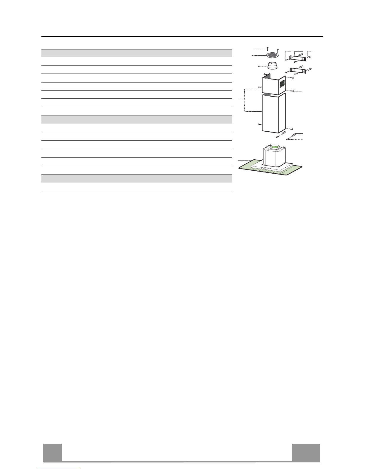
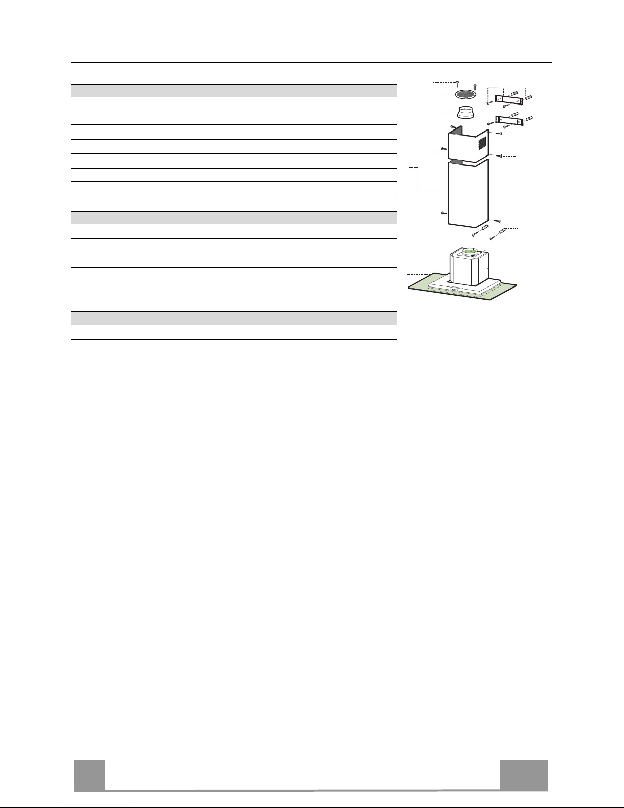
Components
Ref. Q.ty Product Components
1 1 Hood Body, complete with: Controls, Light, Blower, Filters
2 1 Telescopic Chimney comprising:
2.1 1 Upper Section
2.2 1 Lower Section
8 1 Air Outlet Grill
9 1 Reducer Flange ø 150-120 mm
Ref. Q.ty Installation Components
7.2.1 2 Upper Chimney Section Fixing Brackets
11 6 Wall Plugs
12a 6 Screws 4,2 x 44,4
12c 6 Screws 2,9 x 6,5
12e 2 Screws 2,9 x 9,5
Q.ty Documentation
1 Instruction Manual
2.1
2.2
2
12c
12a
7.2.1 11
11
12a
1
9
12e
8
Page 7
EN
7
7
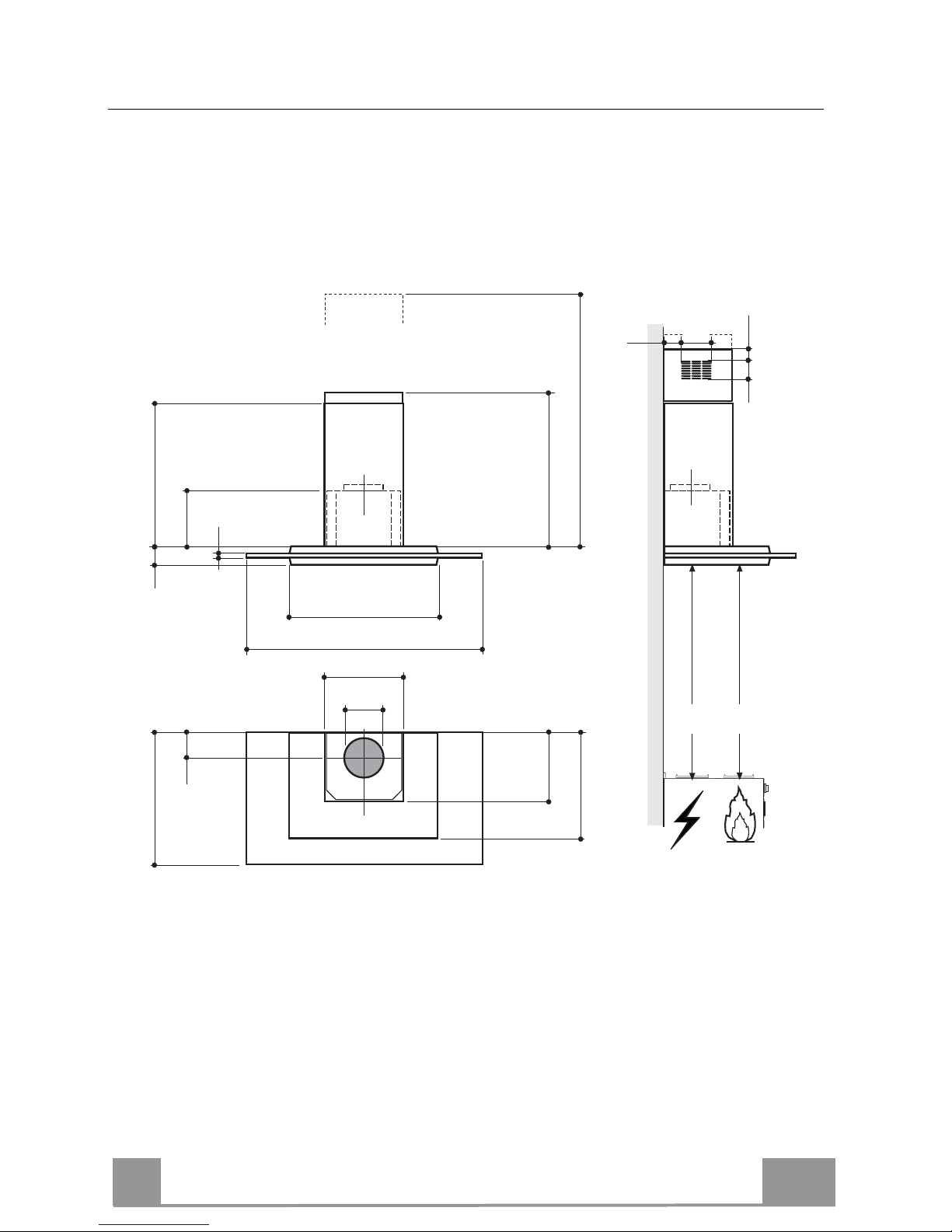
Dimensions
500
400
898
565
68
8
108 259
150
min. 730
max. 1000
540
260
300
Min.
650mm
Min.
650mm
63
4181
126
Page 8
EN
8
8
INSTALLATION
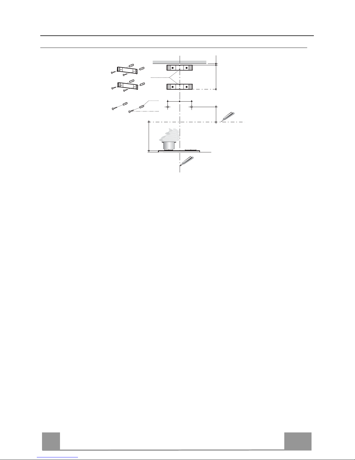
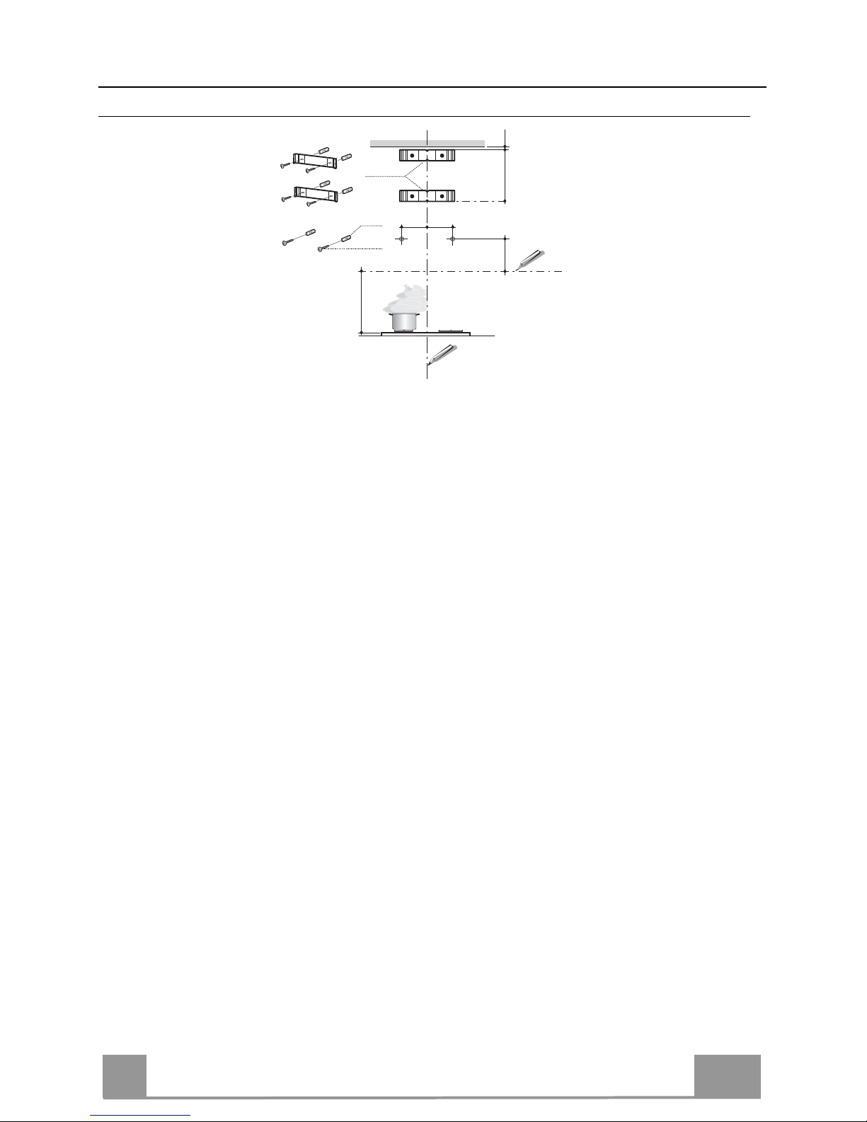
Wall drilling and bracket fixing
Wall marking:
• Draw a vertical line on the supporting wall up to the ceiling, or as high as practical, at the
centre of the area in which the hood will be installed.
• Draw a horizontal line at 650 mm above the hob. Place bracket 7.2.1 on the wall as shown
about 1-2 mm from the ceiling or upper limit aligning the centre (notch) with the vertical
reference line.
• Mark the wall at the centres of the holes in the bracket.
• Place bracket 7.2.1 on the wall as shown at X mm below the first bracket (X = height of the
upper chimney section supplied), aligning the centre (notch) with the vertical line.
• Mark the wall at the centres of the holes in the bracket.
• Mark a reference point as indicated at 116 mm from the vertical reference line and 328 mm
above the horizontal reference line.
• Repeat this operation on the other side.
• Drill ø 8 mm holes at all the centre points marked.
• Insert the wall plugs 11 in the holes.
• Fix the brackets using the 12a (4,2 x 44,4) screws supplied.
• Insert the two screws 12a (4,2 x 44,4) supplied in the hood body fixing holes, leaving a gap
of 5-6 mm between the wall and the head of the screw.
11
12a
328
X
116
1÷2
116
650 min.
7.2.1
Page 9
EN
9
9
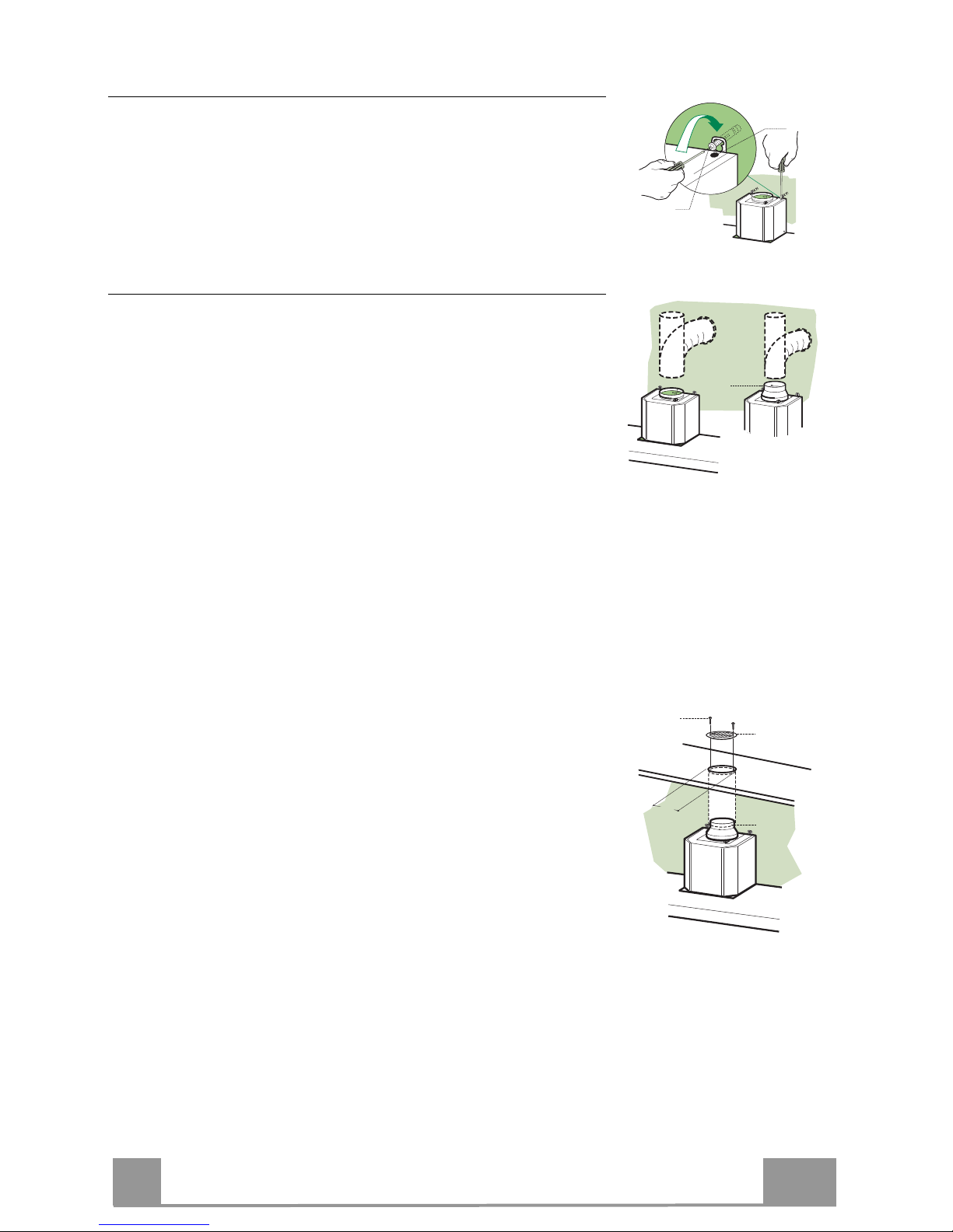
Mounting the hood body
• Before attaching the hood body, tighten the two screws Vr located on the hood body mounting points.
• Hook the hood body onto the screws 12a.
• Fully tighten the support screws 12a.
• Adjust the screws Vr to level the hood body.
12a
Vr
Connections
DUCTED VERSION AIR EXHAUST SYSTEM
When installing the ducted version, connect the hood to the
chimney using either a flexible or rigid pipe ø 150 or 120 mm,
the choice of which is left to the installer.
• To install a ø 120 mm air exhaust connection, insert the reducer flange 9 on the hood body outlet.
• Fix the pipe in position using sufficient pipe clamps (not supplied).
• Remove possible charcoal filters.
9
ø 120ø 150
RECIRCULATION VERSION AIR OUTLET
• Cut a hole ø 125 mm in any shelf that may be positioned over
the hood.
• Insert the reducer flange 9 on the hood body outlet.
• Connect the flange to the outlet on the shelf over the hood by
using a flexible or rigid pipe ø120 mm.
• Fix the pipe in position using sufficient pipe clamps (not supplied).
• Fix the air outlet grid 8 on the recirculation air outlet by using
the 2 screws 12e (2,9 x 9,5) provided.
• Ensure that the activated charcoal filters have been inserted.
9
ø 125
8
12e
Page 10
EN
1
10
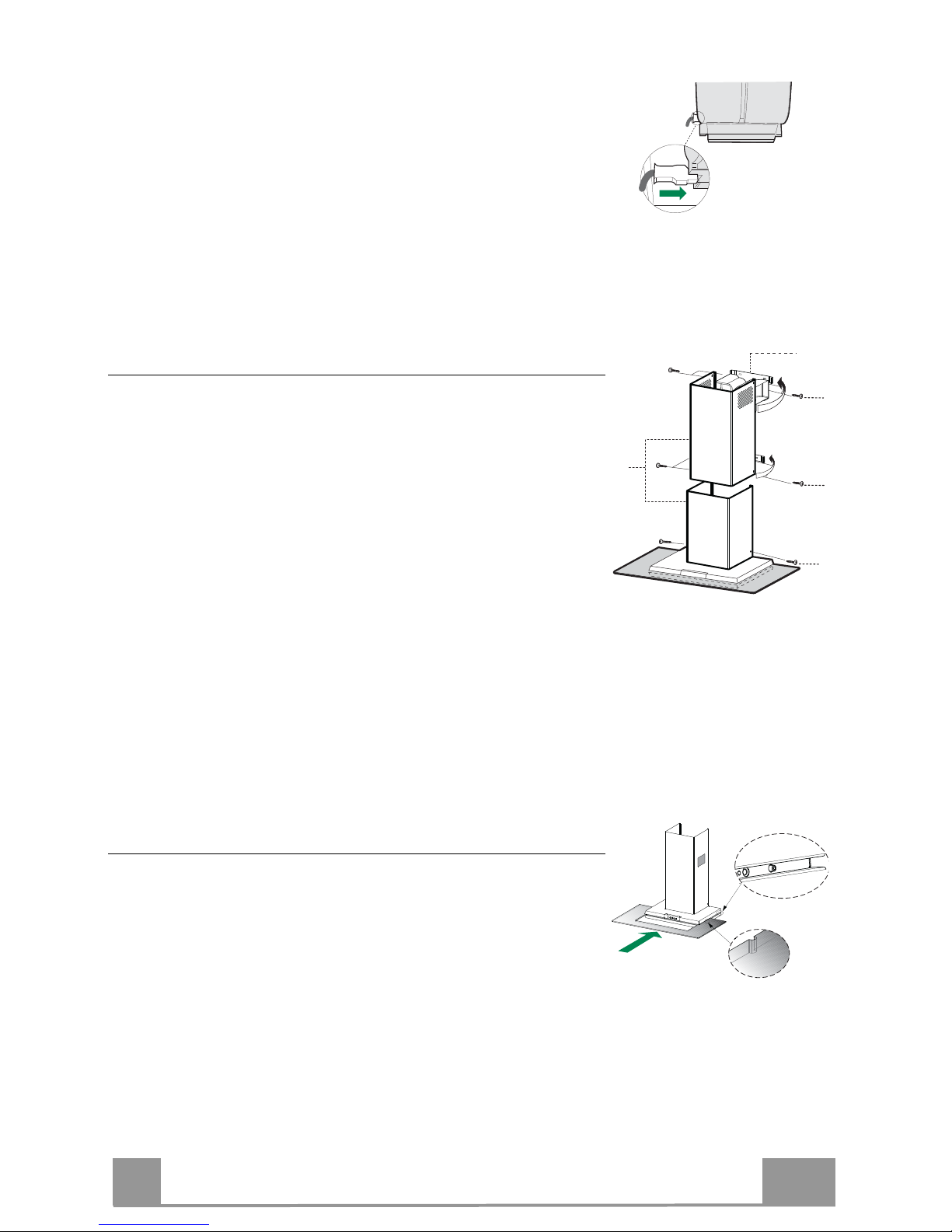
ELECTRICAL CONNECTION
• Connect the hood to the mains through a two-pole switch having a contact gap of at least 3 mm.
• Remove the grease filters (see paragraph Maintenance) being
sure that the connector of the feeding cable is correctly inserted
in the socket placed on the side of the fan.
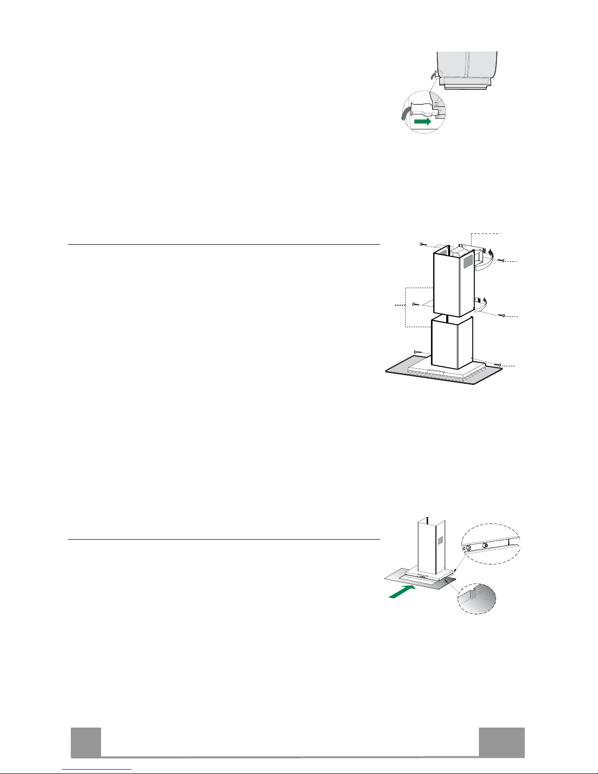
Chimney assembly
Upper exhaust Chimney
• Slightly widen the two sides of the upper chimney and hook
them behind the brackets 7.2.1, making sure that they are well
seated.
• Secure the sides to the brackets using the 4 screws 12c (2,9 x
9,5) supplied.
Lower exhaust Chimney
• Slightly widen the two sides of the chimney and hook them
between the upper chimney and the wall, making sure that they
are well seated.
• Fix the lower part laterally to the hood body using the 2 screws
12c (2,9 x 9,5) supplied.
12c
12c
12c
2.1
2.2
2
7.2.1
Glass assembly
• Push the glass along the groove.
• Check that the pivot “B” is inserted inside the slot “A”.
B
A
Page 11
EN
1
11
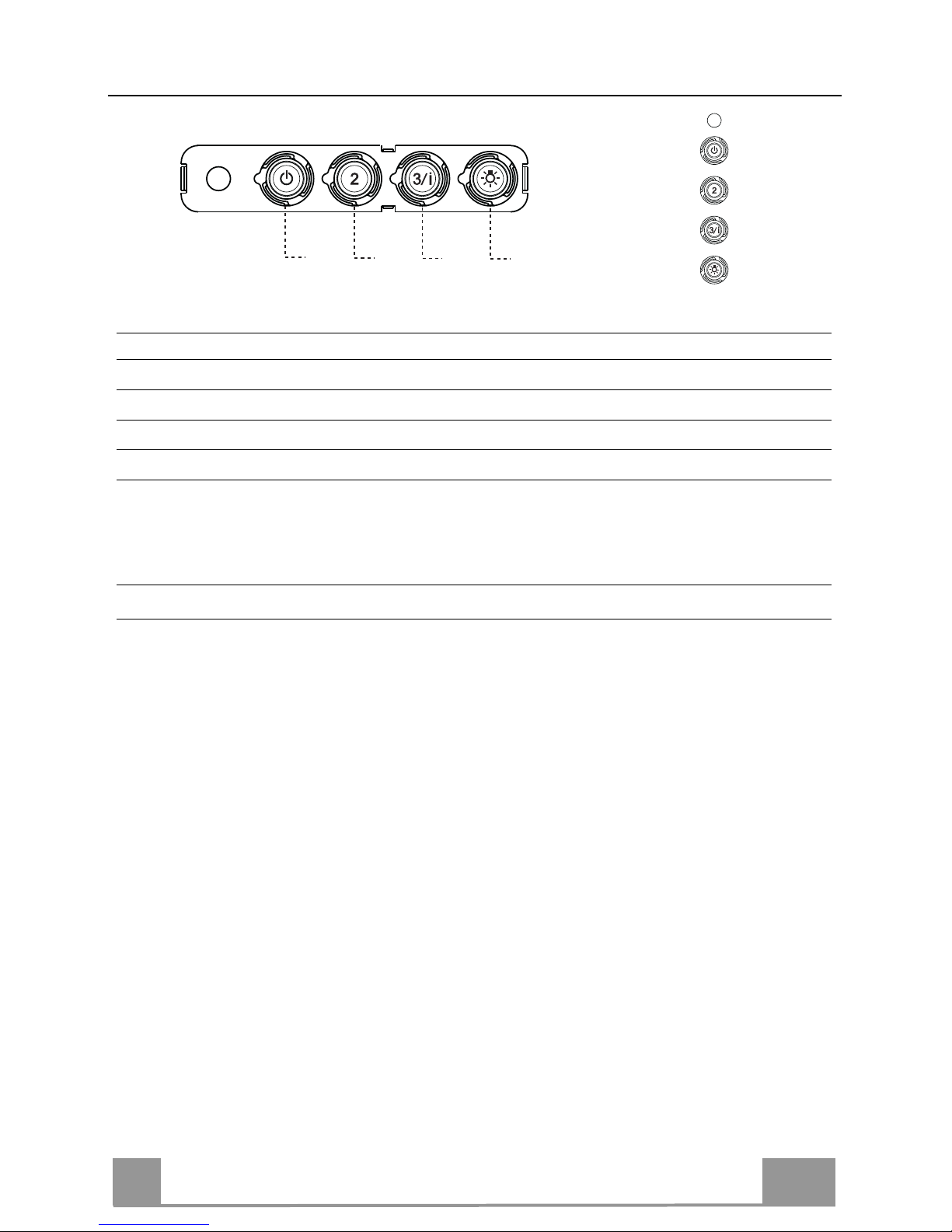
USE
T2
T1
L
T3
Control panel
BUTTON LED FUNCTIONS
T1 Speed On Turns the Motor on at Speed one.
Turns the Motor off.
T2 Speed On Turns the Motor on at Speed two.
T3 Speed Fixed When pressed briefly, turns the Motor on at Speed three.
Flashing Pressed for 2 Seconds.
Activates Speed four with a timer set to 6 minutes, after which
it returns to the speed that was set previously. Suitable to deal
with maximum levels of cooking fumes.
L Light Turns the Lighting System on and off.
Warning: Button T1 turns the motor off, after first passing to speed one.
Page 12
EN
1
12
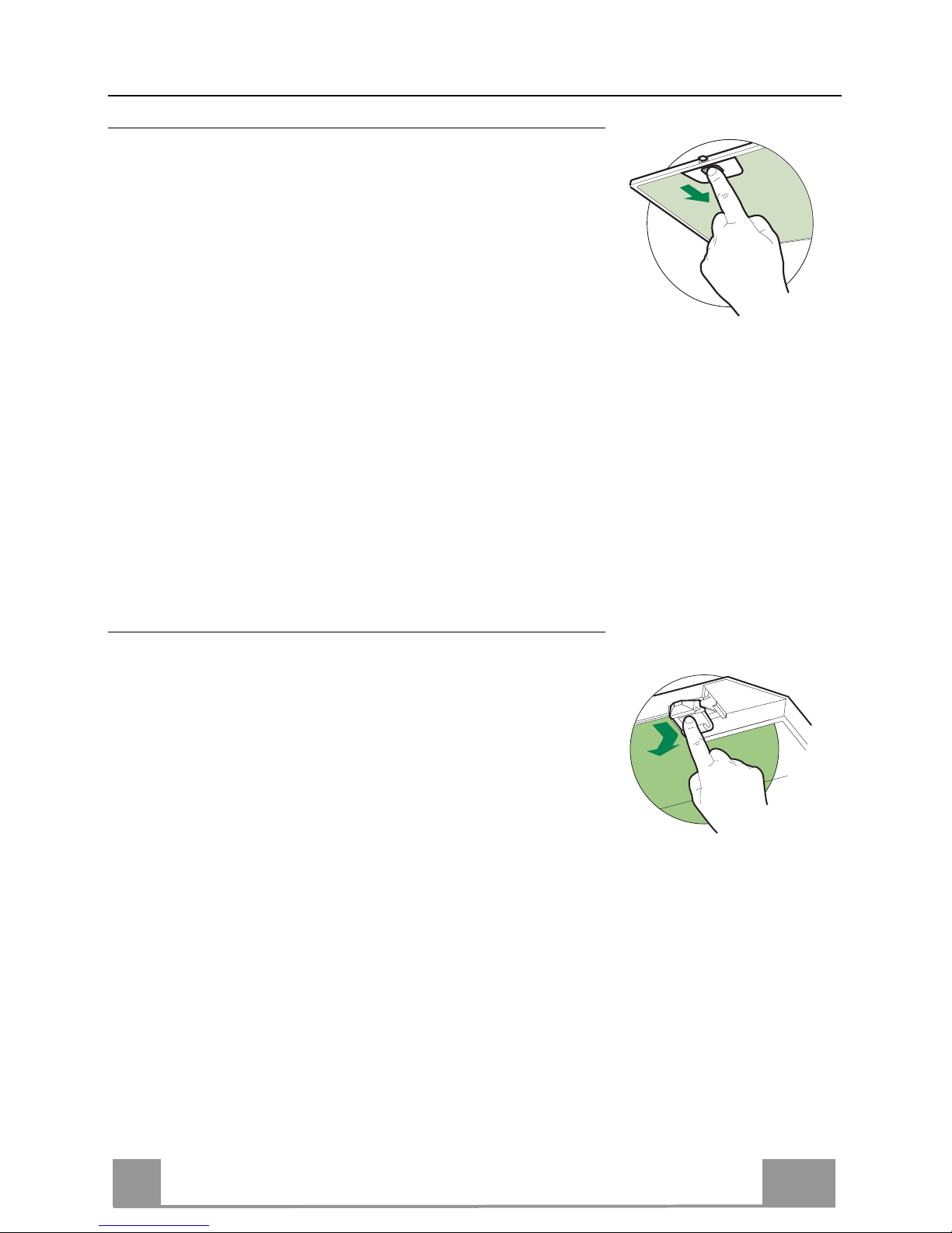
MAINTENANCE
Grease filters
CLEANING METAL SELF- SUPPORTING GREASE FILTERS
• The filters must be cleaned every 2 months of operation, or
more frequently for particularly heavy usage, and can be
washed in a dishwasher.
• Remove the filters one at a time by pushing them towards the
back of the group and pulling down at the same time.
• Wash the filters, taking care not to bend them. Allow them to
dry before refitting.
• When refitting the filters, make sure that the handle is visible
on the outside.
Activated charcoal filter (Recirculation version)
REPLACING THE ACTIVATED CHARCOAL FILTER
• The filter is not washable and cannot be regenerated, and must
be replaced approximately every 4 months of operation, or
more frequently for particularly heavy usage.
• Remove the metal grease filters.
• Remove the saturated activated carbon filter by releasing the
fixing hooks.
• Fit the new filter by hooking it into its seating.
• Refit the metal grease filters.
Page 13
EN
1
13
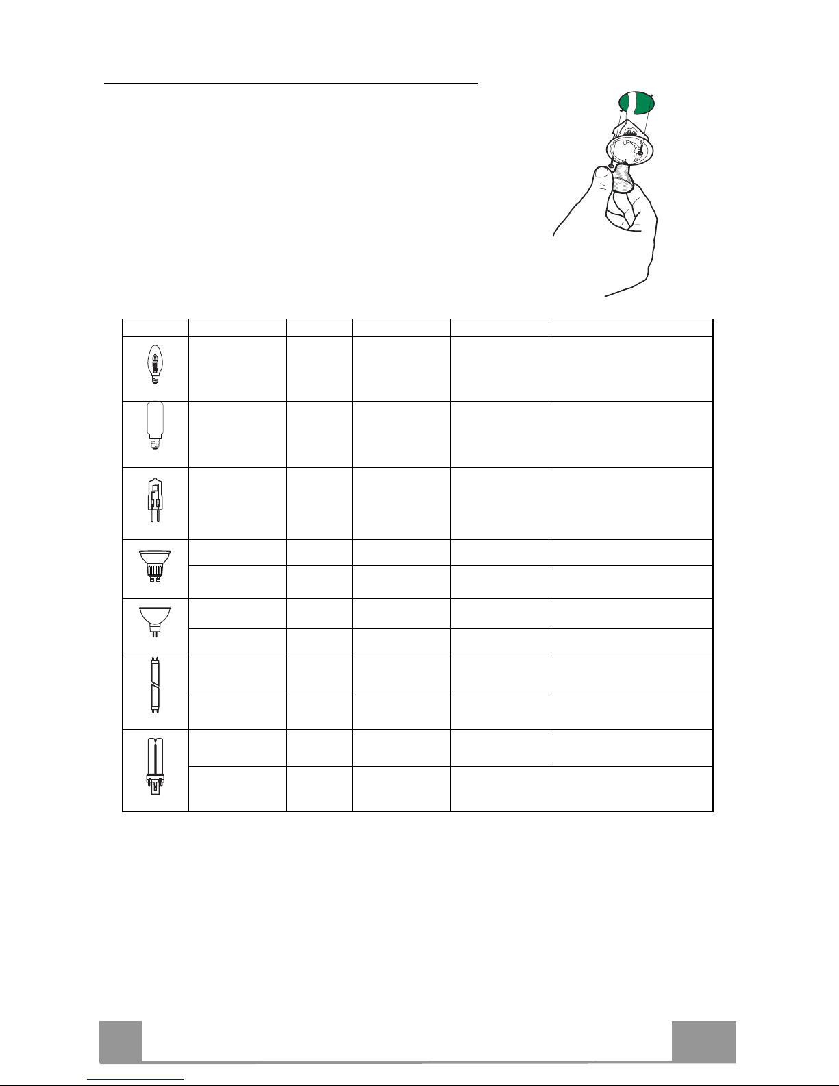
Lighting
LIGHT REPLACEMENT
20 W halogen light.
• Remove the 2 screws fixing the Lighting support, and
pull it out of from the Hood.
• Extract the lamp from the Support.
• Replace with another of the same type, making sure
that the two pins are properly inserted in the lamp
holder socket holes.
• Refit the Support, fixing it in place with the two
screws removed as above.
Lamp Power (W) Socket Voltage (V) Dimension (mm) ILCOS Code
28 E14 220 – 240 104 x 35
HSGSB/C/UB-28-220/240-E14
28 E14 230 85x25
HDG-28-230-E14-25
20 G4 12 33 x 9 HSG/C/UB-20-12-G4
35 GU10 230 51 x 50,7 HAGS-35-230-GU10-51/40
50 GU10 230 51 x 50,7 HAGS-35-230-GU10-51/20
20 GU4 12 40 x 35 HRGS-20-12-GU4-35/30
20 GU5.3 12 46 x 51 HRGS-20-12-GU5.3-50/10
16 G13 95 720 x 26
FD-16/40/1B-E-G13-26/720
18 G13 57 589,8 x 26
FD-18/40/1B-E-G13-26/600
9 G23
60 (lamp)
220-240 (starter)
167 x 28 FSD-9/27/1B-I-G23
11 G23
91 (lamp)
220-240 (starter)
235,8 x 28 FSD-11/40/1B-I-G23
Page 14
RU
1
14
СОВЕТЫ И РЕКОМЕНДАЦИИ
В Инструкциях по эксплуатации описаны различные модели прибора.
Поэтому вы можете встретить описание некоторых характеристик, не
относящихся к приобретенному вами прибору.
УСТАНОВКА
• Изготовитель не несет ответственность за убытки, возникающие в результате
неправильной установки или эксплуатации прибора.
• Безопасное расстояние между варочной панелью и
всасывающей вытяжкой должно быть не менее 650
мм (некоторые модели можно устанавливать ниже; см.
раздел, посвященный рабочим размерам и операциям
по установке прибора).
• Проверьте соответствие напряжения сети указанному
на табличке, закрепленной внутри вытяжки.
• Для приборов класса I проверьте, чтобы в электрической сети вашего дома
была предусмотрена соответствующая система заземления.
Соедините вытяжку с дымоходом с помощью трубы минимального диаметра
120 мм. Труба для отведения дыма должна быть как можно короче.
• Не соединяйте всасывающую вытяжку с дымоходами, по которым выводится
дым, образующийся в процессе горения (например,
отопительные котлы, камины и проч.).
• Если вытяжной аппарат используется в сочетании с
приборами, работающими не от электрического тока
(например, газовые приборы), помещение должно
хорошо проветриваться во избежание обратного
потока отходящих газов. Для притока в помещение
свежего воздуха на кухне должно быть предусмотрено выходящее на улицу
окно. При пользовании кухонной вытяжкой в сочетании с приборами,
работающими не от электрического тока, отрицательное давление в
помещении не должно превышать 0,04 мбар с тем, чтобы дым не всасывался
вытяжкой обратно в помещение.
• Во избежание опасности в случае повреждения кабеля питания, он должен
быть заменен изготовителем или специалистами отдела технического
обслуживания.
2°
Page 15
RU
1
15
• Если в инструкциях по установке газовой плиты сказано, что расстояние до
вытяжки должно быть больше указанного выше, следует
придерживаться предписанных размеров. Соблюдайте все
нормативные требования по отведению отработанного воздуха.
• Используйте только винты и метизы, пригодные для установки
вытяжки. Предупреждение: использование винтов и зажимных
устройств, не соответствующих указаниям данных инструкций, может
привести к возникновению опасных ситуаций и к электрическим ударам.
• Соедините вытяжку с сетью питания с помощью двухполюсного
выключателя с минимальным разведением контактов 3 мм.
ЭКСПЛУАТАЦИЯ
• Всасывающая вытяжка предназначена только для применения в быту
для удаления из кухни запахов от готовки.
• Никогда не пользуйтесь вытяжкой в иных целях, отличных от тех, для
которых она предназначена.
• Никогда не оставляйте высокое пламя под вытяжкой, находящейся в
работе.
• Регулируйте силу пламени таким образом, чтобы оно оставалось под
дном емкости для готовки и не вырывалось за его пределы.
• При готовке во фритюрнице постоянно следите
за ее работой: сильно нагретое масло может
воспламениться.
• Не готовьте блюда фламбе под вытяжкой:
опасность возникновения пожара.
• Прибором могут пользоваться дети старше 8
лет и лица с ограниченными психическими, физическими и сенсорными
способностями, а также не имеющие достаточного опыта и знаний, но
только под присмотром ответственных лиц и при условии, что они
обучены безопасной эксплуатации прибора и знают о связанных с его
неправильным использованием опасностях. Следите, чтобы дети не
играли с прибором. Очистку и уход за прибором должен обеспечивать
пользователь, такие действия могут выполнять и дети, но только под
надзором взрослых.
Page 16

RU
1
16
• “ ВНИМАНИЕ: доступные части вытяжки могут сильно нагреваться во
время работы газовых приборов.
УХОД
• Перед выполнением любой операции по очистке и уходу выключите
или отсоедините прибор от электрической сети.
• Очищайте и/или заменяйте фильтры по истечении указанного периода
времени (опасность возникновения пожара).
• Жировые фильтры необходимо очищать раз в 2 месяца работы или
чаще в случае очень интенсивного использования прибора; жировые
фильтры можно мыть в посудомоечной машине.
• Фильтр на активированном угле нельзя мыть и восстанавливать, его
следует менять примерно раз в 4 месяца работы или чаще в случае
очень интенсивного использования прибора.
• "Опасность возникновения пожара, если очистка прибора не
выполняется в соответствии с инструкциями".
• Очищайте вытяжку влажной тряпкой, смоченной в нейтральном жидком
моющем веществе.
Символ на изделии или на упаковке указывает, что прибор нельзя
выбрасывать, как обычный бытовой мусор. Прибор, подлежащий
уничтожению, необходимо сдать в специальный сборный пункт для
повторного использования электрических и электронных компонентов.
Пользователь, правильно сдающий прибор на переработку, помогает
предотвратить потенциальные негативные последствия для окружающей
среды и для здоровья людей, возникающие в случае неправильного его
уничтожения. За более подробной информацией о вторичном
использовании прибора обращайтесь в городской совет, в местную
службу по переработке отходов или в магазин, где прибор был
приобретен.
Page 17
RU
1
17
ХАРАКТЕРИСТИКИ
cЧасти
Обозн.К-во Части изделия
1 1 Корпус вытяжки в комплекте с ручками управления, освещени-
ем, вентилятором, фильтрами
2 1 Телескопическая дымовая труба, состоящая из:
2.1 1 Верхней дымовой трубы
2.2 1 Нижней дымовой трубы
8 1 Регулируемая решетка
9 1 Переходный фланец ø 150-120 мм
Обозн.К-во Установочные компоненты
7.2.1 2 Крепежные скобы верхней дымовой трубы
11 6 Вкладыши
12a 6 Винты 4,2 x 44,4
12c 6 Винты 2,9 x 6,5
12e 2 Винты 2,9 x 9,5
К-во Документация
1 Bruksanvisning
2.1
2.2
2
12c
12a
7.2.1 11
11
12a
1
9
12e
8
Page 18

RU
1
18
Габариты
500
400
898
565
68
8
108 259
150
min. 730
max. 1000
540
260
300
Min.
650mm
Min.
650mm
63
4181
126
Page 19
RU
1
19
УСТАНОВКА
Сверление стены и крепление скоб
Провести на стене:
• вертикальную линию до потолка или до верхнего предела по центру участка, предусмотренного для установки вытяжки;
• горизонтальную линию на высоте мин. 650 мм от плиты.
Приложить, как показано на рисунке, скобу 7.2.1 к стене на расстоянии 1-2 мм от по-
толка или от верхнего предела, выровняв
ее центр (прорези) по исходной вертикаль-
ной линии.
• Обозначить центры отверстий скобы.
• Приложить, как показано на рисунке, скобу 7.2.1 к стене на расстоянии Х мм под пер-
вой скобой (Х = высота верхней части дымохода, прилагаемого в комплекте), выровнять ее центр (прорези) по исходной вертикальной линии.
• Обозначить центры отверстий скобы.
• Сделать, как показано, отметку на расстоянии 116 мм от исходной вертикальной линии и 328 мм над исходной горизонтальной линией.
• Повторить эту операцию с противоположенной стороны.
• В обозначенным точках просверлить отверстия Ø 8 мм.
• Вставить в отверстия вкладыши 11.
• Закрепить скобы комплектующими винтами 12a ( 4,2 x 44,4).
• Ввинтить 2 прилагаемых винта 12a (4,2 x 44,4) в отверстия крепления
корпуса вытяж-
ки, оставив расстояние 5-6 мм между стеной и головкой винта.
11
12a
328
X
116
1÷2
116
650 min.
7.2.1
Page 20

RU
2
20
Установка корпуса вытяжки
• Прежде чем повесить корпус вытяжки, затянуть 2 винта
Vr, расположенные в точках навески вытяжки.
• Повесить корпус вытяжки на предназначенные винты 12a.
• Затянуть до конца опорные винты 12a.
• Винтами Vr выровнять корпус вытяжки
12a
Vr
Соединения
ВЫПУСК ВОЗДУХА ИЗ ВСАСЫВАЮЩЕЙ ВЫТЯЖКИ
Для установки всасывающей вытяжки соединить ее с выпускной трубой жесткой или гибкой трубкой диаметром 150
или 120 мм, тип которой может выбрать монтажник.
• Для соединения трубкой Ø 120 мм вставить переходный фланец 9 в
выпускное отверстие корпуса вытяжки.
• Закрепить трубку соответствующими трубными зажимами. Необходимый крепежный материал не
входит в ком-
плект.
• Вынуть фильтры от запахов на активном угле.
9
ø 120ø 150
ВЫХОД ВОЗДУХА ИЗ ФИЛЬТРУЮЩЕЙ ВЫТЯЖКИ
• Сделать в полке над вытяжкой отверстие ø 125мм.
• Вставить переходный фланец 9 в выходное отверстие в
корпусе вытяжки.
• Соединить фланец с выпускным отверстием полки над
вытяжкой жесткой или гибкой трубой ø 120 мм.
• Закрепить трубу соответствующими зажимами.
Необходимый для этого материал не входит в комплект
поставки.
•
Закрепить решетку 8 на выпускном отверстии 2
винтами 12e (2,9 x 9,5) (прилагаются).
• Проверить наличие в вытяжке фильтров от запахов на
активном угле.
9
ø 125
8
12e
Page 21
RU
2
21
ЭЛЕКТРИЧЕСКОЕ ПОДКЛЮЧЕНИЕ
• Соединить вытяжку с сетевым напряжением, установив
двухполюсный выключатель с разведением контактов не
менее 3 мм.
• Снять противожировые фильтры (смотри раздел “Уход”)
и проверить правильность положения разъема питающего
кабеля в розетке вытяжки
Установка дымохода
Верхний дымоход
• Слегка развести две боковые кромки дымохода, зацепить
их за скобы 7.2.1 и вновь свести их до упора.
• Закрепить дымоход сбоку 4 входящими в комплект винтами 12c (2,9 x 9,5).
Нижний дымоход
• Слегка развести две боковые кромки дымохода, зацепить
их между верхним дымоходом и стеной и вновь свести их
до упора.
• Закрепить нижнюю часть дымохода сбоку к корпусу вытяжки входящими в комплект 2 винтами 12c (2,9 x 9,5).
12c
12c
12c
2.1
2.2
2
7.2.1
МОНТАЖ СТЕКЛА
• Вставить стекло в ползунки.
• Убедиться в том, что штифт «В» » вошел в углубление
«А».
B
A
Page 22

RU
2
22
ЭКСПЛУАТАЦИЯ
T2
T1
L
T3
Панель управления
КЛАВИША ИНДИКАТОР ФУНКЦИЙ
T1 Скорость Горит Включает двигатель на первой скорости.
Выключает двигатель.
T2 Скорость Горит Включает двигатель на второй скорости.
T3 Скорость Горит Кратким нажатием включает двигатель на
третьей скорости.
Мигает При нажатии в течение 2 секунд.
Включает четвертую скорость на 6 минут, по исте-
чении которых возвращает двигатель на заданную
ранее скорость работы. Функция пригодна для
обработки максимальных объемов дыма от готовки.
L Освещение Включает и выключает осветительную систему.
Внимание: Клавиша T1 выключает двигатель, работа которого всегда проходит через
первую скорость.
Page 23

RU
2
23
УХОД
Противожировые фильтры
ОЧИСТКА МЕТАЛЛИЧЕСКИХ ПРОТИВОЖИРОВЫХ ФИЛЬТРОВ
• Такой фильтр можно также мыть в посудомоечной машине. Мыть фильтр необходимо не реже одного раза в 2 месяца или чаще в случае его активного применения.
• Снять фильтр, для чего прижать его к задней стороне узла
и одновременно потянуть вниз.
• Помыть фильтр, следя за тем,
чтобы он не погнулся, и дать
ему просохнуть.
• Поставить фильтр на место так, чтобы ручка находилась с
наружной стороны и была видна.
Фильтр против запахов (фильтрующая вытяжка)
ЗАМЕНА УГОЛЬНОГО ФИЛЬТРА
• Данный фильтр не моется и не восстанавливается; его следует менять не реже одного раза в 4 месяца или чаще в
случае активного применения.
• Снять металлический противожировой фильтр.
• Отсоединить насыщенный угольный фильтр против запахов
при помощи специальных защелок.
• Установить новый фильтр в положении и закрепить его за
-
щелками.
• Поставить на место металлический противожировой
фильтр.
Page 24

RU
2
24
Освещение
ЗАМЕНА ЛАМП
Галогенные лампы 20 Вт.
• Снять 2 винта крепления патрона и вынуть его из
вытяжки.
• Вынуть из патрона лампу.
• Заменить ее на новую с такими же характеристи-
ками; правильно вставить два штыревых контакта
в гнездо лампового патрона.
• Вновь установить ламповый патрон и закрепить
его снятыми ранее винтами.
Лампа Потребление (Вт) Патрон Напряжение (В) Размер (MM) Код ILCOS
28 E14 220 – 240 104 x 35
HSGSB/C/UB-28-220/240-E14
28 E14 230 85x25
HDG-28-230-E14-25
20 G4 12 33 x 9 HSG/C/UB-20-12-G4
35 GU10 230 51 x 50,7 HAGS-35-230-GU10-51/40
50 GU10 230 51 x 50,7 HAGS-35-230-GU10-51/20
20 GU4 12 40 x 35 HRGS-20-12-GU4-35/30
20 GU5.3 12 46 x 51 HRGS-20-12-GU5.3-50/10
16 G13 95 720 x 26
FD-16/40/1B-E-G13-26/720
18 G13 57 589,8 x 26
FD-18/40/1B-E-G13-26/600
9 G23
60 (лампа)
220-240
(пускатель)
167 x 28 FSD-9/27/1B-I-G23
11 G23
91 (лампа)
220-240
(пускатель)
235,8 x 28 FSD-11/40/1B-I-G23
Page 25

LT
2
25
PATARIMAI IR NUORODOS
Naudojimo instrukcijos taikomos keliems šio prietaiso variantams. Taigi
galite rasti aprašytas tokias savybes, kurios nebūdingos konkrečiam jūsų
prietaisui.
MONTAVIMAS
• Gamintojas nebus atsakingas už jokią žalą, atsiradusią netaisyklingai arba
netinkamai sumontavus prietaisą.
• Mažiausiasis saugus atstumas tarp viryklės
viršaus ir rinktuvo gaubto yra 650 mm (kai kurie
modeliai gali būti montuojami žemiau, žr.
paragrafus apie atstumus ir montavimą).
• Patikrinkite, ar tinklo įtampa atitinka įtampą,
nurodytą ant techninių duomenų lentelės,
esančios gaubto viduje.
• Patikrinkite, ar I klasės prietaisai yra tinkamai
įžeminti.
Rinktuvą prijunkite prie ventiliacijos kanalo, naudokite ne mažesnio kaip 120
mm skersmens vamzdį. Atstumas nuo garų rinktuvo iki ventiliacijos kanalo
turėtų būti kuo trumpesnis.
• Garų rinktuvo nejunkite prie dūmtakių, per kuriuos šalinami degimo metu
susidarę dūmai (boilerių, židinių ir t. t.).
• Jei rinktuvas yra naudojamas ne su elektros
įrenginiais (pvz., dujų degikliais), kambaryje turi
būti įrengta tinkama ventiliacija, kad išmetamosios
dujos nepatektų atgal į patalpą. Tarp virtuvės ir
lauko turi būti tiesioginė orlaidė, kad į patalpą
galėtų patekti gryno oro. Kai gartraukis yra
naudojamas su įrenginiais, kuriems reikalinga
kitokia energijos rūšis (ne elektra), neigiamas
slėgis patalpoje neturi viršyti 0,04 mbar – taip bus užtikrinta, kad gartraukis
nestums garų į patalpą.
• Jei pažeidžiamas elektros kabelis, jį turi pakeisti gamintojas arba techninės
priežiūros skyrius, kad būtų išvengta bet kokių pavojų.
2°
Page 26

LT
2
26
• Jei pagal dujų degiklio įrengimo instrukcijas nurodomas didesnis atstumas, į
tai turi būti atsižvelgta. Tai pat reikia laikytis nurodymų, kurie reguliuoja oro
išmetimą.
• Gartraukiui tvirtinti naudokite tik sraigtus ir mažas dalis.
Įspėjimas! Jei sraigtai ar tvirtinimo priemonės nebus montuojami pagal šias
instrukcijas, tai gali sukelti elektros saugumo pavojų.
• Prijunkite gaubtą į elektros tinklą, naudodami dvipolį jungiklį, tarpas tarp
kontaktų turi būti ne mažesnis nei 3 mm.
NAUDOJIMAS
• Garų rinktuvas buvo sukurtas naudoti tik namuose virtuvės kvapams šalinti.
• Rinktuvo niekada nenaudokite kitiems tikslams, kurie nenumatyti
instrukcijoje.
• Garų rinktuvui veikiant, po juo niekada nepalikite didelės atviros ugnies.
• Sureguliuokite liepsnos intensyvumą taip, kad liepsna būtų nukreipta į
keptuvės apačią, ji negali apimti šonų.
• Naudodami gilią keptuvę, turite būti atidūs:
perkaitęs aliejus gali užsiliepsnoti.
• Po garų surinktuvu negaminkite patiekalų, kuriuos
prieš patiekimą ant stalo užpila spiritu arba
konjaku ir uždega; yra gaisro pavojus.
• Šį prietaisą gali naudoti 8 metų ir vyresni vaikai
bei asmenys, turintys fizinių, jutiminių ar protinių gebėjimų sutrikimų, taip pat
asmenys, nemokėję ir nežinoję, kaip elgtis su prietaisu, jei tokie asmenys
yra prižiūrimi, buvo apmokyti, kaip saugiai su juo elgtis, ir supranta esamą
pavojų. Vaikams negalima žaisti su prietaisu. Vaikams valymo ir priežiūros
darbų atlikti be priežiūros negalima.
Page 27

LT
2
27
• ATSARGIAI! Jei viryklės naudojamos, rankomis paliečiamos dalys gali būti
karštos.
PRIEŽIŪRA
• Prieš atlikdami bet kokius priežiūros darbus, prietaisą išjunkite arba
ištraukite kištuką iš elektros tinklo.
• Po nurodyto laiko išvalykite ir (arba) pakeiskite filtrus (dėl gaisro pavojaus).
• Riebalų filtrai turi būti valomi kas 2 darbo mėnesius arba dažniau, jei viryklė
ir rinktuvas naudojami labai intensyviai; filtrus galima plauti indaplove.
• Aktyvuotos anglies filtras yra neplaunamas ir antrą kartą nenaudojamas, turi
būti pakeistas apytiksliai kas 4 darbo mėnesius arba dažniau, jei viryklė ir
garų surinktuvas naudojami intensyviai.
• Neatlikus numatyto valymo, gali kilti gaisro pavojus.
• Rinktuvą valykite drėgnu skudurėliu, naudodami neutralų skystą ploviklį.
Ant gaminio arba jo pakuotės esantis simbolis nurodo, kad šis prietaisas
nepriskiriamas prie įprastų buities atliekų. Prietaisas turi būti perduotas į
reikiamą surinkimo punktą, užsiimantį elektros ir elektroninės įrangos
perdirbimu. Tinkamai sunaikindami šį gaminį, aplinką ir žmogaus sveikatą
apsaugosite nuo galimų neigiamų pasekmių, kurių gali atsirasti dėl netinkamo
šio gaminio utilizavimo. Norėdami gauti daugiau informacijos apie šio gaminio
utilizavimą, kreipkitės į vietines miesto institucijas, savo buitinių atliekų
tvarkymo tarnybą arba parduotuvę, kurioje prietaisą nusipirkote.
Page 28

LT
2
28
PRIETAISO APRAŠYMAS
Sudedamosios dalys
Nuor. Kiekis Gaminio sudedamosios dalys
1 1 Gaubto korpusas su: valdymo elementais, lempute, pūstuvu, filtrais
2 1 Teleskopinis kaminas, susidedantis iš:
2.1 1 viršutinės sekcijos
2.2 1 apatinės sekcijos
8 1 Oro išleidimo grotelės
9 1 ø 150–120 mm redukcinė jungė
Nuor. Kiekis Montavimo sudedamosios dalys
7.2.1 2 Viršutinės kamino sekcijos fiksavimo laikikliai
11 6 Sienos kamščiai
12a 6 4,2 x 44,4 sraigtai
12c 6 2,9 x 6,5 sraigtai
12e 2 2,9 x 9,5 sraigtai
Kiekis Dokumentacija
1 Instrukcijos vadovas
2.1
2.2
2
12c
12a
7.2.1 11
11
12a
1
9
12e
8
Page 29

LT
2
29
Kliūtis
500
400
898
565
68
8
108 259
150
min. 730
max. 1000
540
260
300
Min.
650mm
Min.
650mm
63
4181
126
Page 30

LT
3
30
MONTAVIMAS
Sienos gręžimas ir laikiklio tvirtinimas
Sienos žymėjimas:
• Ant atraminės sienos nubrėžkite vertikalią liniją iki perdangos arba iki tokio aukščio, koks
būtų praktiškas; brėžkite per vietos, kurioje gartraukis bus montuojamas, centrinę dalį.
• Nubrėžkite horizontalią liniją 650 mm virš degiklio. Laikiklį 7.2.1 tvirtinkite prie sienos
taip, kaip parodyta. Palikite apie 1–2 mm atstumą nuo lubų ar viršutinės ribos; centras
(išpjova) turi atitikti vertikalią orientacinę liniją.
• Sienoje pažymėkite laikiklio skylių centrus.
• Laikiklį 7.2.1 tvirtinkite prie sienos taip, kaip parodyta, X mm žemiau pirmo laikiklio (X =
pateiktos viršutinės kamino dalies aukštis); centras (išpjova) turi atitikti vertikalią liniją.
• Sienoje pažymėkite laikiklio skylių centrus.
• Pažymėkite orientacinį tašką taip, kaip parodyta, 116 mm atstumą palikite nuo vertikalios
orientacinės linijos, 328 mm atstumą – nuo horizontalios orientacinės linijos.
• Pakartokite šį veiksm
ą kitoje pusėje.
• Išgręžkite ø 8 mm skyles visų pažymėtų taškų centruose.
• Į skyles įkiškite sienos kamščius 11.
• Pritvirtinkite laikiklius, naudodami pateiktus sraigtus 12a (4,2 x 44,4).
• Du pateikiamus sraigtus 12a (4,2 x 44,4) įkiškite į gartraukio gaubto tvirtinimo skyles,
palikdami 5–6 mm tarpą tarp sienos ir sraigto galvutės.
11
12a
328
X
116
1÷2
116
650 min.
7.2.1
Page 31

LT
3
31
Gartraukio korpuso montavimas
• Prieš užkabinant gartraukio korpusą prisukti 2 varžtus Vr kurie
randasi gartraukio korpuso prikabinimo vietoje.
• Užkabinti gartraukio korpusą ant varžtų 12a.
• Prisukti glutinai laikymo varžtus Vr kad susilygintų gartraukio
korpusas.
• Gartraukio korpuso balansavimui naudoti Vr varžtus.
12a
Vr
Pajungimas
ORO IŠĖJIMAS TRAUKIMO BŪDU
Norint instaliuoti traukimo versiją pajunkite gartraukį prie
išeinamojo kietojo arba lankstaus 150 arba 120 mm diametro
vamzdžio pagal jūsų pasirinkimą.
• Norint prijungti su 120 mm diametro vamzdžiu įveskite
reduktorių 9 į dūmtraukio korpuso išeigą.
• Pritvirtinti vamzdį su specialiais prisukimo instrumentais. Šie
instrumentai nėra įtraukti į komplektą.
• Išimti kvapą sutraukiančius anglies filtrus.
9
ø 120ø 150
RECIRKULIACINĖS VERSIJOS ORO IŠĖJIMO ANGA
• Išgręžkite 125 mm skersmens skylę bet kurioje lentynoje, kuri
gali būti pritvirtinta virš gaubto.
• Reduktoriaus jungę 9 uždėkite ant gaubto korpuso angos.
• Jungę prijunkite prie ant lentynos esančios angos, naudokite
lankstų arba standų 120 mm skersmens vamzdį.
• Vamzdį pritvirtinkite nustatyta padėtimi, naudokite reikiamus
vamzdžio tvirtinimo elementus (nepateikiami).
• Oro išleidimo groteles 8 pritvirtinkite prie recirkuliacinės oro
angos, naudodami 2 pateikiamus sraigtus 12e (2,9 x 9,5).
• Įsitikinkite, ar aktyvintosios anglies filtrai buvo įdėti.
9
ø 125
8
12e
Page 32

LT
3
32
PAJUNGIMAS PRIE ELEKTROS
• Pajungti gartraukį į tinklą panaudojant bipolinį jungiklį su
mažiausiai 3mm kontaktų atidarymu.
• Išimti riebalų sulaikymo filtrus (žiūreti par. Eksploatacija)
Kamino montavimas
Viršutinis kaminas
• Truputį praplėsti du šoninius kraštus, užkabinti ant laikymo
bėgių 7.2.1 ir uždaryti iki fiksacijos.
• Pritvirtinti laikiklio šoninėse dalyse 4 varžtus 12c (2,9 x 9,5)
kuriuos jūs rasite pakuotėje.
Apatinis kaminas
• Truputį praplėsti du kamino šoninius kraštus, užkabinti juos
tarp viršutinio kamino ir sienos ir uždaryti iki fiksacijos.
• Pritvirtinti iš šonų viršutinę gartraukio korpuso dalį 2 varžtais
12c (2,9 x 9,5) kuriuos jūs rasite pakuotėje.
12c
12c
12c
2.1
2.2
2
7.2.1
Stiklo detalės surinkimas
• Stumtelkite stiklą išilgai griovelio.
• Patikrinkite, ar tvirtinimo detalė „B“ yra įdėta į kiaurymę „A“.
B
A
Page 33

LT
3
33
NAUDOJIMAS
T2
T1
L
T3
VALDYMO SKYDELIS
MYGTUKAS DAVIKLIS FUNKCIJOS
T1 Greitis Įjungtas. Paleidžia variklį pirmu greičiu.
Sustabdo variklį.
T2 Greitis Įjungtas. Paleidžia variklį antru greičiu.
T3 Greitis Nustatytas Trumpai spustelėjus paleidžia variklį trečiu greičiu.
Blykčiojantis Spaudžiamas 2 sekundes. Aktyvuoja ketvirtą greitį, laikmatis
nustatomas 6 minučių, paskui grįžtama prie anksčiau nustatyto
greičio. Tinka tada, kai reikia ištraukti daug garų, susidariusių
gaminant maistą.
L Apšvietimas Įjungia ir išjungia apšvietimo sistemą.
Įspėjimas! Mygtukas T1 sustabdo variklį, pirmiau perėjus prie pirmo greičio.
Page 34

LT
3
34
VALYMAS IR PRIEŽIŪRA
Riebalus sulaikantys filtrai
METALINIŲ RIEBALŲ FILTRŲ VALYMAS
• Gali būti plaunami indų plovimo mašinoje, būtina plauti kas 2
mėnesius ar dažniau jei naudojama ypač daug.
• Nuimti filtus po vieną pastumiant juos tuo pačiu metu į
užpakalinę pusę ir patraukiant į apačią.
• Plaunant stengtis nesulenkti filtrų ir prieš įdėjimą nusausinti.
• Įdėti atgal paliekant rankeną išorinėje, matomoje pusėje.
Kvapų surinkimo filtras (filtravamo būdas)
KVAPŲ SURINKIMO FILTRO PAKEITIMAS Į ANGLIES FILTRĄ
• Šis filtras yra neplaunamas ir neatnaujinamas, turi būti keičia-
mas kas 4 mėnesius ar dažniau, jei naudojama ypač daug.
• Pašalinti riebalų surinkimo metalinius filtrus.
• Nuimti pilnai prisigėrusį kvapo surinkimo anglies filtrą naudojant tam skirtus kabliukus.
• Įdėti naują filtrą pritaisant jį savo buvusioje vietoje.
• Atgal sudėti riebalų surinkimo metalinius filtrus.
Page 35

LT
3
35
Apšvietimas
Lempučių keitimas
20 W halogeninė lemputė.
• Išsukite 2 sraigtus, fiksuojančius lemputės atramą, ir
ištraukite ją iš gaubtuvo.
• Išsukite lemputę iš atramos.
• Keiskite kita to paties tipo lempute, įsitikinę, ar du
kaištukai yra tinkamai įdėti į lemputės laikiklio
skyles.
• Vėl įdėkite atramą, užfiksuodami ją anksčiau
išsuktais sraigtais.
Lemputė Galingumas (W) Lizdas Įtampa (V) Matmenys (mm) ILCOS kodas
28
E14
220–240
104 x 35 HSGSB/C/UB-28-220/240-E14
28 E14 230 85x25
HDG-28-230-E14-25
20 G4 12 33 x 9 HSG/C/UB-20-12-G4
35 GU10 230 51 x 50,7 HAGS-35-230-GU10-51/40
50 GU10 230 51 x 50,7 HAGS-35-230-GU10-51/20
20 GU4 12 40 x 35 HRGS-20-12-GU4-35/30
20 GU5.3 12 46 x 51 HRGS-20-12-GU5.3-50/10
16 G13 95 720 x 26
FD-16/40/1B-E-G13-26/720
18 G13 57 589,8 x 26
FD-18/40/1B-E-G13-26/600
9 G23
60 (lemputė)
220–240
(starteris)
167 x 28
FSD-9/27/1B-I-G23
11 G23
91 (lemputė)
220–240
(starteris)
235,8 x 28 FSD-11/40/1B-I-G23
Page 36

LV
3
36
IETEIKUMI UN PRIEKŠLIKUMI
Lietošanas norādījumi attiecas uz vairākām šīs ierīces versijām. Tādējādi
iespējams, ka atradīsit atsevišķas funkcijas, kas nepiemīt konkrētajai
ierīcei.
UZSTĀDĪŠANA
• Izgatavotājs neuzņemas atbildību par bojājumiem, kas radušies nepareizas
uzstādīšanas rezultātā.
• Minimālais drošais attālums starp plīts virsmu un
tvaiku nosūcēju ir 650 mm (dažus modeļus var
uzstādīt zemāk, skatiet sadaļu par darba izmēriem
un uzstādīšanu).
• Pārbaudiet vai strāva mājas elektrotīklā atbilst
tehnisko datu plāksnītē norādītajā, kas
piestiprināta nosūcēja iekšpusē.
• 1. klases ierīces gadījumā pārbaudiet, vai mājas
elektrotīkls nodrošina pareizu zemējumu.
Pievienojiet nosūcēju izvades plūsmai ar cauruli 120 mm diametrā. Plūsmas
ceļam jābūt pēc iespējas īsākam.
• Nepievienojiet nosūcēju izplūdes cauruļvadiem, kas izvada sadegšanas
atlikuma produktus (boileri, kamīni utt.).
• Ja nosūcējs tiek izmantots kopā ar neelektriskām
ierīcēm (piem., gāzes plītīm), telpā jānodrošina
pietiekama ventilācija, lai nepieļautu izvadāmi
gāzu plūšanu atpakaļ. Virtuvei jābūt aprīkotai ar
atveri, pa kuru var ieplūst āra gaiss. Ja tvaika
nosūcējs uzstādīts savienojumā ar neelektriskā
ierīcēm, telpas negatīvais spiediens nedrīkst
pārsniegt 0,04 mbar, lai nepieļautu garaiņu
ieplūšanu atpakaļ telpā.
• Gadījumā, ja bojāts strāvas padeves kabelis, to jānomaina izgatavotāja vai
tehniskās apkalpošanas dienesta pārstāvim, lai nepieļautu nekādus riskus.
2°
Page 37

LV
3
37
• Ja gāzes plīts uzstādīšanas instrukcijās norādīts lielāks attālums, nekā
noteikts iepriekš, tad tas ir jāņem vērā. Jāizpilda noteikumi, kas saistīti ar
gaisa atbrīvošanu.
• Tvaika nosūcēja atbalstam izmantot tikai skrūves un mazās sastāvdaļas.
Brīdinājums: Ja skrūvju vai stiprinājuma ierīces uzstādīšanā nav ievērotas
šīs instrukcijas, tad var rasties elektriskās strāvas trieciena riski.
• Pievienojiet elektrotīklam ar divu polu slēdža palīdzību, kam saskares
atstarpe ir vismaz 3 mm.
IZMANTOŠANA
• Tvaika nosūcējs ir izstrādāts ekskluzīvi lietošanai mājsaimniecībā, lai
novērstu virtuves smakas.
• Nekad nelietot tvaika nosūcēju tādiem mērķiem, kādiem to nav paredzēts
lietot.
• Nekad zem funkcionējoša tvaika nosūcēja neatstāt lielas atklātas liesmas.
• Noregulēt liesmas intensitāti tikai tieši zem pannas, pārliecinoties, ka liesma
atrodas arī ārpus pannas malām.
• Dziļās tauku cepšanas ierīces lietošanas laikā ir
nepārtraukti jānovēro: pārkarsēta eļļa var liesmās
sadegt.
• Neuzstādīt zem tvaika nosūcēja gabarītiem;
aizdegšanās risks.
• Šo ierīci lietot drīkst 8 gadus veci un vecāki bērni,
kā arī personas ar ierobežotām fiziskām, sensoriskām vai garīgām spējām,
vai personas, kam nav pieredzes un zināšanu, ja tām ir nodrošināta
uzraudzība vai instrukcijas, kas saistītas ar drošu ierīces lietošanu un
ietverto bīstamības risku izpratni. Bērni nedrīkst spēlēties ar ierīci. Tīrīšanu
un ierīces kopšanu nedrīkst veikt bērni, ja tie netiek uzraudzīti.
Page 38

LV
3
38
• “ UZMANĪBU: Atklātās detaļas gatavošanas iekārtu izmantošanas laikā var
kļūt karstas.”
APKOPE
• Pirms jebkādu apkopes darbu veikšanas atslēdziet ierīci no elektrotīkla.
• Tīriet un/vai mainiet filtrus pēc noteikta laika perioda (aizdegšanās
briesmas).
• Tauku filtri jātīra ik pēc 2 darbības mēnešiem vai biežāk, ja ierīce tiek
intensīvi lietota, filtrus var mazgāt trauku mazgājamajā mašīnā.
• Aktīvās ogles filtrs nav mazgājams un nav atjaunojams, to jāmaina apmēram
pēc 4 mēnešu darbības vai biežāk, ja ierīce tiek izmantota intensīvi.
• Nespēja veikt tīrīšanu, kā norādīts var izraisīt ugunsbīstamību.
• Nosūcēju tīriet ar mitru lupatiņu un neitrālu šķidru mazgāšanas līdzekli.
Simbols uz izstrādājuma un tam pievienotajos dokumentos nozīmē, ka šo
ierīci nedrīkst izmest kopā ar parastiem sadzīves atkritumiem. Tā jānodod
elektrisko vai elektronisko preču savākšanas punktā, kur tos pieņem
pārstrādei. Nodrošinot šī izstrādājuma pareizu utilizāciju, Jūs palīdziet novērst
potenciāli negatīvu ietekmi uz vidi un cilvēku veselību, kas tomēr var notikt, ja
neievērosiet šī izstrādājuma utilizācijas noteikumus. Lai iegūtu
papildinformāciju par šī produkta pārstrādi, sazinieties ar savu pašvaldību,
vietējo atkritumu savākšanas dienestu vai veikalu, kurā iegādājāties šo
produktu.
Page 39

LV
3
39
TEHNISKIE DATI
Sastāvdaļas
Ats. Daudz. Izstrādājuma sastāvdaļas
1 1 Tvaiku nosūcēja korpuss, komplektā ar: vadības elementiem,
apgaismojumu, ventilatoru, filtriem
2 1 Izbīdāmais dūmenis, kas sastāv no:
2.1 1 Augšējā daļa
2.2 1 Apakšējā daļa
8 1 Gaisa izplūdes režģis
9 1 Sašaurināšanas uzmava ø 150-120 mm
Ats. Daudz. Uzstādīšanas sastāvdaļas
7.2.1 2 Augšējās dūmvada daļas fiksācijas kronšteini
11 6 Sienas dībeļi
12a 6 Skrūves 4,2 x 44,4
12c 6 Skrūves 2,9 x 6,5
12e 2 Skrūves 2,9 x 9,5
Daudz. Dokumentācija
1 Lietošanas pamācība
2.1
2.2
2
12c
12a
7.2.1 11
11
12a
1
9
12e
8
Page 40

LV
4
40
Izmēri
500
400
898
565
68
8
108 259
150
min. 730
max. 1000
540
260
300
Min.
650mm
Min.
650mm
63
4181
126
Page 41

LV
4
41
UZSTĀDĪŠANA
Sienas urbšana un kronšteinu nostiprināšana
Atzīmes uz sienas:
• Novelciet vertikālu līniju uz balsta sienas līdz griestiem, vai, ja tas ir praktiskāk, tās vietas
centrā, pie kuras nosūcējs tiks uzstādīts.
• Novelciet horizontālu līniju 650 mm virs plīts virsmas. Pielieciet kronšteinu 7.2.1 pie sienas
kā parādīts apmēram 1-2 mm no griestiem vai augšējā ierobežojuma, salāgojot centru
(ierobi) ar vertikālo atsauces līniju.
• Atzīmējiet uz sienas kronšteinu atveru centrus.
• Atbalstīt kronšteinu 7.2.1 pie sienas, kā norādīts, X mm attālumā zem pirmā kronšteina (X =
uzstādītās dūmvada augšdaļas augstums), izlīdzinot tā centru (gropes) l
īdz ar vertikālo
atsauces līniju.
• Atzīmējiet uz sienas kronšteinu atveru centrus.
• Atzīmējiet atsauces punktu kā parādīts, 116 mm no vertikālās atsauces līnijas un 328 mm
virs horizontālās atsauces līnijas.
• Atkārtojiet šo darbību otrā pusē.
• Izurbt ø 8 mm atveres visos atzīmētajos centra punktos.
• Ievietot atverēs sienas dībeļus 11.
• Nofiksēt kronšteinus, izmantojot komplektā ietvertās 12a skrūves (4,2 x 44,4).
• Ievietot divas komplektā ietvertās skrūves 12a (4,2 x 44,4) tvaika nosūcēja fiksācijas
atverēs, atstājot atstarpi 5-6 mm starp sienu un skrūves galviņu.
11
12a
328
X
116
1÷2
116
650 min.
7.2.1
Page 42

LV
4
42
Atsūcēja korpusa uzstādīšana
• Pirms pievienojat atsūcēja korpusu, pievelciet divas skrūves
Vr, kas atrodas korpusa montāžas punktos.
• Uzāķējiet korpusu uz skrūvēm 12a.
• Līdz galam pievelciet atbalsta skrūves 12a.
• Noregulējiet skrūves Vr līdz atsūcēja korpusa līmenim.
12a
Vr
Savienojums
CAURUĻVADU VERSIJAS IZPLŪDES SISTĒMA
Uzstādot cauruļvada versiju, pievienojiet nosūcēju dūmvadam,
izmantojot elastīgu vai cietu cauruli ø 150 vai 120 mm, izvēli atstājiet uzstādītāja ziņā.
• Lai uzstādītu ø 120 mm gaisa izplūdes savienojumu, ievietojiet
samazinātāja uzmavu 9 tvaika nosūcēja korpusa izvadē.
• Fiksējiet cauruli ar atbilstošām caurules skavām (nav ietverti).
• Izņemt iespējamos aktivētās ogles filtrus.
9
ø 120ø 150
RECIRKULĀCIJAS VERSIJAS IZPLŪDE
• Izgrieziet ø 125 atveri visos plauktos, zem kuriem tiks uzstādīts
atsūcējs.
• Ievietojiet samazinātāja atloci 9 atsūcēja korpusa izvadē.
• Savienojiet atloci ar izplūdi plauktā virs atsūcēja ar elastīgu vai
cietu ø120 mm cauruli.
• Fiksējiet cauruli ar atbilstošām caurules skavām (nav ietvertas
komplektā)
• Piestipriniet izplūdes režģi 8 pie recirkulācijas gaisa izplūdes,
izmantojot 2 komplektā ietvertās skrūves 12e (2,9 x 9,5).
• Pārliecinieties, ka aktīvās ogles filtri ir uzstādīti.
9
ø 125
8
12e
Page 43

LV
4
43
ELEKTRISKAIS SAVIENOJUMS
• Pievienojiet elektrotīklam ar divu polu slēdža palīdzību, kam
saskares atstarpe ir vismaz 3 mm.
• Izņemiet tauku filtrus (skatiet sadaļu „Apkope”), pārliecinoties,
ka padeves kabelis ir pareizi ievietots kontaktligzdā, kas atrodas ventilatora sānos.
Dūmvada montāža
Augšējais izplūdes dūmvads
• Nedaudz paplašiniet augšējā dūmvada abas puses un aizāķējiet
tās aiz skavām 7.2.1, pārliecinoties, ka tās labi piegulst.
• Nostipriniet sānus pie skavām ar 4 komplektā ietilpstošajām
skrūvēm 12c (2,9 x 9,5).
Apakšējais izplūdes dūmvads
• Nedaudz paplašiniet augšējā dūmvada abas puses un aizāķējiet
tās starp augšējo dūmvadu un sienu, pārliecinoties, ka tās labi
piegulst.
• Fiksējiet apakšējo daļu šķērsām nosūcēja korpusam, izmantojot
2 komplektā ietilpstošās skrūves 12c (2,9 x 9,5).
12c
12c
12c
2.1
2.2
2
7.2.1
Stikla konstrukcija
• Bīdīt stiklu gar gropi.
• Pārbaudīt, vai šarnīrs "B" ir ievietots gropes "A" iekšpusē.
B
A
Page 44

LV
4
44
IZMANTOŠANA
T2
T1
L
T3
Vadības panelis
TAUSTIŅŠ DIODE FUNKCIJAS
T1 Ātrums Iesl. Ieslēdz motoru ar pirmo ātrumu.
Izslēdz motoru.
T2 Ātrums Iesl. Ieslēdz motoru ar otro ātrumu.
T3 Ātrums Fiksēts Viegli piespiežot, ieslēdz motoru ar trešo ātrumu.
Mirgo Piespiests uz 2 sekundēm.
Aktivizē ceturto ātrumu ar laika slēdzi iestatītu uz 6 minūtēm, pēc tam
ieslēdzas iepriekš iestatītais ātrums. Piemērots darbībām, kad
gatavošanas laikā izdalās daudz tvaiku.
L Apgaismojums Ieslēdz un izslēdz apgaismojuma sistēmu.
Brīdinājums: Ar taustiņu T1 izslēdz motoru, vispirms ieslēdzot pirmo ātrumu.
Page 45

LV
4
45
APKOPE
Tauku filtri
METĀLA PAŠBALSTOŠO TAUKU FILTRU TĪRĪŠANA
• Filtri jātīra ik pēc 2 darbības mēnešiem vai biežāk, ja ierīce tiek
intensīvi lietota, filtrus var mazgāt trauku mazgājamajā mašīnā.
• Izņemiet filtrus pa vienam, spiežot tos virzienā uz grupas aizmuguri un vienlaicīgi velkot uz leju.
• Izmazgājiet filtrus, uzmanieties, lai nesalocītu. Pirms uzstādī-
šanas rūpīgi izžāvējiet.
• Uzstādot filtrus atpakaļ, pārliecinieties, ka rokturis ir redzams
no ārpuses.
Aktivētās ogles filtrs (Recirkulācijas versija)
AKTIVĒTĀS OGLES FILTRA MAIŅA
• Filtrs nav mazgājams un nav atjaunojams, to jāmaina apmēram
pēc 4 mēnešu darbības vai biežāk, ja ierīce tiek izmantota intensīvi.
• Noņemiet metāla tauku filtrus.
• Izņemiet piesārņotos aktivētās ogles filtrus, atlaižot fiksācijas
āķus.
• Uzstādiet jauno filtru, iekabinot to savā vietā.
• Noņemiet metāla tauku filtrus.
Page 46

LV
4
46
Apgaismojums
SPULDŽU MAIŅA
20 W halogēna spuldze
• Izņemiet 2 skrūves, kas fiksē atbalstu un izvelciet to ārā
no tvaiku atsūcēja.
• Izņemiet spuldzi no balsta.
• Nomainiet ar jaunu tāda paša tipa spuldzi, pārliecinieties,
ka divas tapiņas ir pareizi ievietota spuldzes turētāja
atverēs.
• Uzlieciet atpakaļ balstu, fiksējiet to savā vietā ar divām
pirms tam izņemtajām skrūvēm.
Lampa Jauda (W) Ligzda Spriegums (V) Gabarīti (mm) ILCOS kods
28 E14 220 – 240 104 x 35
HSGSB/C/UB-28-220/240-E14
28 E14 230 85x25
HDG-28-230-E14-25
20 G4 12 33 x 9 HSG/C/UB-20-12-G4
35 GU10 230 51 x 50,7 HAGS-35-230-GU10-51/40
50 GU10 230 51 x 50,7 HAGS-35-230-GU10-51/20
20 GU4 12 40 x 35 HRGS-20-12-GU4-35/30
20 GU5.3 12 46 x 51 HRGS-20-12-GU5.3-50/10
16 G13 95 720 x 26
FD-16/40/1B-E-G13-26/720
18 G13 57 589,8 x 26
FD-18/40/1B-E-G13-26/600
9 G23
60 (lampa)
220-240 (starteris)
167 x 28 FSD-9/27/1B-I-G23
11 G23
91 (lampa)
220-240 (starteris)
235,8 x 28 FSD-11/40/1B-I-G23
Page 47

EE
4
47
SOOVITUSED JA ETTEPANEKUD
Kasutusjuhised kehtivad selle seadme mitmele versioonile. Seetõttu võite
siit leida individuaalsete funktsioonide kirjeldusi, mis ei kehti teie
spetsiifilisele seadmele.
PAIGALDAMINE
• Tootja ei vastuta mingite kahjustuste eest, mille põhjuseks on ebaõige
paigaldamine.
• Minimaalne ohutu vahemaa pliidi pinna ja
pliidikummi vahel on 650 mm (mõned mudelid on
paigaldatavad madalamale, palun vaadake
töömõõtmete ja paigaldamise lõike).
• Veenduge, et vooluvõrgu pinge vastaks
pliidikummi sisse kinnitatud andmeplaadil toodule.
• I klassi seadmete puhul veenduge, et
majapidamistoide garanteeriks adekvaatse
maanduse.
Ühendage pliidikumm tõmbelõõriga vähemalt 120 mm läbimõõduga toru
abil. Tee lõõrini peab olema võimalikult lühike.
• Ärge ühendage pliidikummi põlemisaurusid (boilerid, kaminad jne) kandvate
tõmbelõõridega.
• Kui pliidikummi kasutatakse koos mitte-elektriliste
seadmetega (nt gaasipliidid), tuleb heitgaaside
tagasivoolamise vältimiseks tagada ruumis piisav
õhuvahetus. Köögil peab olema puhta õhu
sisenemise garanteerimiseks otsene ühendus
vaba õhuga. Pliidikummi kasutamisel koos
seadmetega, mille energiaallikaks ei ole elekter, ei
tohi ruumi negatiivne rõhk ületada 0,04 mbar, et
vältida aurude tagasi tõmbamist ruumi pliidikummi poolt.
• Toitekaabli kahjustuste korral tuleb ohtude vältimiseks lasta see tootja või
tehnilise hoolduse osakonna poolt asendada.
2°
Page 48

EE
4
48
• Kui gaasipliidi paigaldusjuhised määravad suurema ülaltoodud vahemaa,
tuleb arvestada sellega. Täidetud peavad olema õhu väljutamisega seotud
määrused.
• Kasutage pliidikummi toetamiseks ainult kruvisid ja väikesi osi.
Hoiatus: Kruvide või kinnitusseadme mitte vastavalt nendele juhistele
paigaldamine võib põhjustada elektriohtusid.
• Ühendage pliidikumm võrgutoitega vähemalt 3 mm kontaktivahega
kahepooluselise lülitiga.
KASUTAMINE
• Pliidikumm on loodud eksklusiivselt koduseks kasutamiseks köögilõhnade
eemaldamiseks.
• Ärge kasutage seda kunagi eesmärkidel, mille jaoks see mõeldud pole.
• Ärge jätke töötava pliidikummi alla kunagi kõrgeid avatud leeke.
• Reguleerige leekide tugevust nii, et need oleks suunatud ainult panni põhjale
ega ei haaraks selle külgesid.
• Rasvas kuumutamisel tuleb seda pidevalt jälgida:
ülekuumutatud õli võib põlema süttida.
• Ärge pliidikummi all flambeerige – tuleoht.
• 8-aastased ja vanemad lapsed ning isikud, kellel
on piiratud füüsilised, sensoorsed või vaimsed
võimed või kellel puuduvad kogemused ja
teadmised seadme kasutamise kohta, võivad seda seadet kasutada, kui
neid jälgitakse või juhendatakse seadme ohutul kasutamisel ning nad
mõistavad sellega seotud ohtusid. Lapsed ei tohi seadmega mängida.
Puhastamist ja kasutajapoolset hooldust ei tohi teostada järelevalveta
lapsed.
Page 49

EE
4
49
• “ ETTEVAATUST: Ligipääsetavad osad võivad koos
toiduvalmistusseadmetega kasutamisel kuumaks minna.”.
HOOLDUS
• Enne hooldustööde teostamist lülitage seade välja või ühendage see
võrgutoitest lahti.
• Määratud perioodi möödumisel puhastage või vahetage filtrid (tuleoht).
• Rasvafiltrid tuleb puhastada iga 2 kasutuskuu järel, eriti suurel
kasutuskoormusel sagedamini, ning pesta nõudepesumasinas.
• Aktiivsöefilter ei ole pestav ega regenereeritav ning tuleb vahetada ligikaudu
iga 4 kasutuskuu järel või eriti suurel kasutuskoormusel sagedamini.
• "Puhastamise siintoodud viisil mitte teostamise tagajärjeks on tulekahju oht."
• Puhastage pliidikummi niiske lapi ja neutraalse vedela puhastusvahendiga.
sümbol toote või selle pakendi peal tähendab seda, et antud toodet ei saa
käsitleda olmeprügina. Selle asemel tuleb see anda üle elektrilise ja
elektroonilise varustuse jäätmete ümbertöötlemisega tegelevale asutusele.
Toote õige kõrvaldamise tagamisega aitate te ära hoida võimalikke
negatiivseid tagajärgi keskkonnale ja inimeste tervisele, mis võib vastasel juhul
tekkida selle toote vale käsitlemise käigus. Täpsemat teavet selle toote
ümbertöötlemise kohta saate te oma linnakantseleist, olmejäätmete
kõrvaldamise teenistusest või poest, kust te selle toote ostsite.
Page 50

EE
5
50
OMADUSED
Komponendid
Viide Kogus Toote komponendid
1 1 Pliidikummi korpus koos järgmisega: juhikud, valgusti, puhur, filtrid
2 1 Teleskoopkorsten, mille osadeks on:
2.1 1 Ülemine osa
2.2 1 Alumine osa
8 1 Õhu väljalaskevõre
9 1 Siirdmikäärik ø 150-120 mm
Viide Kogus Paigalduskomponendid
7.2.1 2 Korstna ülemise osa kinnitusklambrid
11 6 Tüüblid
12a 6 Kruvid 4,2 x 44,4
12c 6 Kruvid 2,9 x 6,5
12e 2 Kruvid 2,9 x 9,5
Kogus Dokumentatsioon
1 Kasutusjuhend
2.1
2.2
2
12c
12a
7.2.1 11
11
12a
1
9
12e
8
Page 51

EE
5
51
Mõõdud
500
400
898
565
68
8
108 259
150
min. 730
max. 1000
540
260
300
Min.
650mm
Min.
650mm
63
4181
126
Page 52

EE
5
52
PAIGALDAMINE
Seina puurimine ja klambri kinnitamine
Seina märgistamine:
• Tõmmake tugiseinale pliidikummi paigaldusala keskele vertikaalne joon laeni või nii
kõrgele kui praktiline.
• Tõmmake 650 mm kõrgusele pliidist horisontaalne joon. Asetage klamber 7.2.1 näidatud
viisil seinale 1-2 mm kaugusele laest või ülemisest piirist, joondades keskkoha (sälk)
vertikaalse viitejoonega.
• Märgistage sein klambri aukude keskkohtades.
• Asetage klamber 7.2.1 näidatud viisil seinale X mm esimesest klambrist allapoole (X =
kaasas oleva korstna ülemise osa kõrgus), joondades keskkoha (sälk) vertikaalse joonega.
• Märgistage sein klambri aukude keskkohtades.
• Märgistage näidatud viitepunkt 116 mm vertikaalsest viitejoonest ja 328 mm kõrgusel
horisontaalsest viitejoonest.
• Korrake seda teisel küljel.
• Puurige ø 8 mm augud kõikidesse märgistatud keskpunktidesse.
• Asetage aukudesse tüüblid 11.
• Kinnitage klambrid kaasas olevate 12a (4,2 x 44,4) kruvidega.
• Sisestage kaks kaasas olevat kruvi 12a (4,2 x 44,4) pliidikummi korpuse paigaldusavadesse,
jättes seina ja kruvi pea vahele 5-6 mm vahemaa.
11
12a
328
X
116
1÷2
116
650 min.
7.2.1
Page 53

EE
5
53
Pliidikummi korpuse paigaldamine
• Enne pliidikummi korpuse kinnitamist pinguldage kaks kruvi
Vr, mis asuvad pliidikummi korpuse kinnituspunktides.
• Riputage pliidikummi korpus kruvidele 12a.
• Pinguldage tugikruvid 12a täielikult.
• Reguleerige kruvid Vr pliidikummi korpuse loodi seadmiseks.
12a
Vr
Ühendused
TORUSTIKUGA VERSIOONI ÕHUIMUSÜSTEEM
Torustikuga versiooni paigaldamisel ühendage pliidikumm korstnaga painduva või jäiga ø 150 või 120 mm toru abil, selle valik
jääb paigaldajale.
• ø 120 mm õhuimuühenduse paigaldamiseks sisestage pliidi-
kummi korpuse väljundile siirdmikäärik 9.
• Kinnitage toru kohale piisava hulga toruklambrite abil (ei ole
kaasas).
• Eemaldage võimalikud söefiltrid.
9
ø 120ø 150
RETSIRKULATSIOONIGA VERSIOONI ÕHUVÄLJUND
• Lõigake ø 125 mm ava kõigisse pliidikummi kohal asuda või-
vatesse riiulitesse.
• Asetage siirdmikäärik 9 pliidikummi korpuse väljundile.
• Ühendage äärik pliidikummi kohal oleval riiulil väljundiga
ø120 mm vooliku või toru abil.
• Kinnitage toru kohale piisava hulga toruklambrite abil (ei ole
kaasas).
• Kinnitage õhuväljundi võre 8 retsirkulatsiooniõhu väljundile 2
lisatud kruviga 12e (2,9 x 9,5).
• Kindlustage, et aktiivsöefiltrid oleks paigaldatud.
9
ø 125
8
12e
Page 54

EE
5
54
ELEKTRIÜHENDUS
• Ühendage pliidikumm võrgutoitega vähemalt 3 mm kontakti-
vahega kahepooluselise lülitiga.
• Eemaldage rasvafiltrid (vt lõiku Hooldus) veendudes, et toite-
kaabli ühendus on ventilaatori küljele asetatud pessa õigesti sisestatud.
Korstna koostamine
Ülemine tõmbekorsten
• Laiendage ülemise korstna kahte külge kergelt ja haakige need
klambrite 7.2.1 taha veendudes, et need istuvad hästi.
• Kinnitage küljed klambritega 4 kaasas oleva kruviga 12c (2,9 x
9,5).
Alumine tõmbekorsten
• Laiendage korstna kahte külge kergelt ja haakige need ülemise
korstna ja seina vahele veendudes, et need istuvad hästi.
• Kinnitage alumine osa külgsuunas pliidikummi korpusega 2
kaasas oleva kruviga 12c (2,9 x 9,5).
12c
12c
12c
2.1
2.2
2
7.2.1
Klaasi koostamine
• Vajutage klaasi piki soont.
• Veenduge, et pöördetelg „B“ oleks sisestatud pessa „A“.
B
A
Page 55

EE
5
55
KASUTAMINE
T2
T1
L
T3
Juhtpaneel
NUPP VALGUSDIOOD FUNKTSIOONID
T1 Kiirus Sees Lülitab mootori sisse esimesel kiirusel.
Lülitab mootori välja.
T2 Kiirus Sees Lülitab mootori sisse teisel kiirusel.
T3 Kiirus Fikseeritud Lühikesel vajutusel lülitab mootori sisse kolmandal kiirusel.
Vilgub Hoides 2 sekundit.
Aktiveerib neljanda kiiruse 6 minutile seatud taimeriga, mille
järel pöördub süsteem tagasi eelnevalt seatud kiirusele. Sobib
maksimaalsete lõhnatasemete käsitsemiseks.
L Valgustus Valgustussüsteemi sisse- ja väljalülitamine.
Hoiatus: Nupp T1 lülitab mootori pärast esmalt esimesele kiirusele lülitamist välja.
Page 56

EE
5
56
HOOLDUS
Rasvafiltrid
METALLIST ISESEISVATE RASVAFILTRITE PUHASTAMINE
• Filtrid tuleb puhastada iga 2 kasutuskuu järel, eriti suurel kasu-
tuskoormusel sagedamini, ning pesta nõudepesumasinas.
• Eemaldage filtrid ükshaaval, surudes neid grupi tagaosa suunas
ning samal ajal allapoole tõmmates.
• Peske filtrid, vältides samal ajal nende painutamist. Laske neil
enne uuesti paigaldamist kuivada.
• Filtrite uuesti paigaldamisel veenduge, et käepide oleks väljast
nähtaval.
Aktiivsöefilter (retsirkulatsiooniga versioon)
AKTIIVSÖEFILTRI VAHETAMINE
• Filter ei ole pestav ega regenereeritav ning tuleb vahetada ligi-
kaudu iga 4 kasutuskuu järel või eriti suurel kasutuskoormusel
sagedamini.
• Eemaldage metallist rasvafiltrid
• Eemaldage küllastunud aktiivsöefilter, vabastades kinnitus-
konksud
• Paigaldage uus filter, kinnitades selle konksudega kohale
• Paigaldage metallist rasvafiltrid tagasi.
Page 57

EE
5
57
Valgustus
VALGUSTUSE VAHETAMINE
20 W halogeenpirn.
• Eemaldage valgustuse tuge paigal hoidvad 2 kruvi ja
tõmmake see pliidikummist välja.
• Eemaldage lamp toest.
• Asendage see teise sama tüüpi lambiga veendudes, et
mõlemad tihvtid on õigesti lambihoidiku pesa avadesse sisestatud.
• Paigaldage tugi tagasi, kinnitades selle kohale eemaldatud kahe kruviga.
Pirn Võimsus (W) Pesa Pinge (V) Mõõtmed (mm) ILCOS kood
28 E14 220 – 240 104 x 35
HSGSB/C/UB-28-220/240-E14
28 E14 230 85x25
HDG-28-230-E14-25
20 G4 12 33 x 9
HSG/C/UB-20-12-G4
35 GU10 230 51 x 50,7 HAGS-35-230-GU10-51/40
50 GU10
230 51 x 50,7 HAGS-35-230-GU10-51/20
20 GU4 12 40 x 35 HRGS-20-12-GU4-35/30
20 GU5.3
12 46 x 51 HRGS-20-12-GU5.3-50/10
16 G13 95 720 x 26
FD-16/40/1B-E-G13-26/720
18 G13
57 589,8 x 26
FD-18/40/1B-E-G13-26/600
9 G23
60 (pirn)
220-240 (starter)
167 x 28
FSD-9/27/1B-I-G23
11 G23
91 (pirn)
220-240 (starter)
235,8 x 28
FSD-11/40/1B-I-G23
Page 58

SA
5
58
تﺎﺣاﺮﺘﻗا و تادﺎﺷرا
تﺎﻤﻴﻠﻌﺗ ماﺪﺨﺘﺳﻻا ﻩﺬه ﻲه جذﺎﻤﻨﻟ ﺔﻔﻠﺘﺨﻣ ﻦﻣ اﺬه زﺎﻬﺠﻟا. ،ﻚﻟﺬﻟ ﺪﻗ ﺪﺠﺗ ﺎﻔﺻو ﺺﺋﺎﺼﺨﻟ
ﺔﻳدﺮﻓ ﺪﻗ ﻻ ﻖﺒﻄﻨﺗ ﻰﻠﻋ زﺎﻬﺠﻟا صﺎﺨﻟا ﻚﺑ ﺪﻳﺪﺤﺘﻟﺎﺑ.
ﺐﻴآﺮﺘﻟا
• ﻊﻨﺼﻤﻟا ﻲﻠﺨﻳ ﻪﺴﻔﻧ ﻦﻣ ﺔﻴﻟوﺆﺴﻤﻟا ﻩﺎﺠﺗ راﺮﺿﻷا ﺔﺠﺗﺎﻨﻟا ﻦﻋ ﺐﻴآﺮﺘﻟا ﺄﻄﺨﻟا أو لﺎﻤﻌﺘﺳﻻا
ﺄﻄﺨﻟا.
• ﺔﻓﺎﺴﻤﻟا ﻲﻓ ﺪﺤﻟا ﻰﻧدﻷا ﺔﻣﻼﺴﻠﻟ ﻦﻴﺑ ﺢﻄﺳ ﺦﺒﻄﻟا
ﺔﻨﺧﺪﻤﻟاو ﺐﺠﻳ نأ نﻮﻜﺗ 650 ،ﻢﻣ )ﺾﻌﺑ تﻼﻳدﻮﻤﻟا
ﻦﻜﻤﻳ ﺎﻬﺒﻴآﺮﺗ ﻰﻠﻋ عﺎﻔﺗرا ،ﻞﻗأ ﻰﺟﺮﻳ عﻮﺟﺮﻟا ﻰﻟا
تاﺮﻘﻓ مﺎﺠﺣﻷا ﺐﻴآﺮﺘﻟاو(.
• ﺪآﺄﺗ ﻦﻣ نأ رﺎﻴﺘﻟا ﻲﺋﺎﺑﺮﻬﻜﻟا ﻖﺑﺎﻄﻣ ﺎﻤﻟ ﻮه رﺎﺸﻣ ﻪﻴﻟإ
ﻲﻓ ﺔﺣﻮﻠﻟا ةدﻮﺟﻮﻤﻟا ﺧادﻞ ﺔﻨﺧﺪﻤﻟا.
• ةﺰﻬﺟﻸﻟ ﻦﻣ ﺔﺌﻔﻟا ﻰﻟوﻷا I، ﺐﺠﻳ ﺪآﺄﺘﻟا ﻦﻣ ﺔﻜﺒﺷ
ﺔﻳﺬﻐﺘﻟا ﺔﻴﺋﺎﺑﺮﻬﻜﻟا ﺎﻬﻧﺄﺑ ﺔﺿرﺆﻣ.
ﻢﻗ ﻞﻴﺻﻮﺘﺑ زﺎﻬﺟ ﻂﻔﺸﻟا بﻮﺒﻧﺄﺑ جﺮﺨﻣ نﺎﺧﺪﻟا ﻂﺳاﻮﺑ
بﻮﺒﻧأ ﻩﺮﻄﻗ 120 ﻢﻣ. ﺐﺠﻳ نأ نﻮﻜﻳ رﺎﺴﻣ نﺎﺧﺪﻟا ﺮﺼﻗأ ﺎﻣ نﻮﻜﻳ.
• ﻻ ﻢﻘﺗ ﻞﻴﺻﻮﺘﺑ ﺔﻨﺧﺪﻤﻟا ﺔﻄﻓﺎﺸﻟا ﺐﻴﺑﺎﺒﻧﺄﺑ ﺔﻠﺼﺘﻣ ردﺎﺼﻤﺑ ﺔﻳراﺮﺣ ﺔﺠﺘﻨﻣ نﺎﺧﺪﻠﻟا )لﺎﺜﻤآ
ﻰﻠﻋ ﻚﻟذ ،تﺎﻧﺎﺨﺴﻟا ﺊﻓاﺪﻤﻟا ﺦﻟا(.
• اذا ﻢﺗ ماﺪﺨﺘﺳا ﻂﻓﺎﺸﻟا ﻊﻣ ةﺰﻬﺟأ ﺮﻴﻏ ﺔﻴﺋﺎﺑﺮﻬآ )لﺎﺜﻤآ
ﻰﻠﻋ ﻚﻟذ ةﺰﻬﺟأ ﻞﻤﻌﺗ زﺎﻐﻟﺎﺑ(، ﺐﺠﻳ نﺎﻤﺿ ﺔﻳﻮﻬﺗ
ةﺪﻴﺟ ﺔﻴﻓﺎآو ﻲﻓ نﺎﻜﻤﻟا ﻦﻣ ﻞﺟأ ﻊﻨﻣ داﺪﺗرا ﻖﻓد
زﺎﻐﻟا ﺪﻨﻋ جوﺮﺨﻟا. ﺐﺠﻳ نأ ﻚﻠﺘﻤﻳ ﺦﺒﻄﻤﻟا ﺔﺤﺘﻓ
ةﺮﺷﺎﺒﻣ ﻰﻟا جرﺎﺨﻟا ﻦﻣ ﻞﺟأ نﺎﻤﺿ لﻮﺧد ءاﻮﻬﻟا
ﻒﻴﻈﻨﻟا نﺎﻜﻤﻠﻟ .ﺪﻨﻋ ماﺪﺨﺘﺳا ﺔﻨﺧﺪﻣ ﺦﺒﻄﻤﻟا ﻊﻣ
تاﺪﻌﻤﻟا ﻲﺘﻟا ﻻ ىﺬﻐﺘﺗ ﻦﻣ رﺎﻴﺘﻟا ،ﻲﺋﺎﺑﺮﻬﻜﻟا ﺐﺠﻳ
نأ ﻻ زوﺎﺠﺘﻳ ﻂﻐﻀﻟا ﻲﺒﻠﺴﻟا ﻲﻓ نﺎﻜﻤﻟا0,04 م رﺎﺑ
ﻊﻨﻤﻟ ةﺮﺨﺑﻷا ﻦﻣ داﺪﺗرﻻا ﻰﻟا ﻞﺧاد ﺦﺒﻄﻤﻟا ﻦﻋ ﻖﻳﺮﻃ ﺔﻨﺧﺪﻤﻟا.
• ﻲﻓ ﺔﻟﺎﺣ ﻒﻠﺗ ﻚﻠﺳ ﺔﻗﺎﻄﻟا ﺔﻴﺋﺎﺑﺮﻬﻜﻟا، ﺐﺠﻳ ﻪﻠﻳﺪﺒﺗ ﻦﻣ ﻞﺒﻗ ﺔآﺮﺸﻟا ﺔﻌﻨﺼﻤﻟا وأ ﻦﻣ ﺔﻣﺪﺧ
ﺔﻧﺎﻴﺼﻟا ﻲﺘﻟا ﺎﻬﻠّﺜﻤﺗ ﺐﻨﺠﺘﻟ يأ ﺮﻄﺧ.
2°
Page 59

SA
5
59
•
اذإ
ﺖﻧﺎآ
تﺎﻤﻴﻠﻌﺗ
ﺐﻴآﺮﺗ
ﺢﻄﺳ
ﺦﺒﻄﻟا
زﺎﻐﻟﺎﺑ
دﺪﺤﺗ
ﺔﻓﺎﺴﻣ
ﺮﺒآأ
ﻦﻣ
ﻲﺘﻟا
ةدراو
،ﻩﻼﻋأ
ﺐﺠﻴﻓ
ﺬﺧﻷا
ﻩﺬﻬﺑ
تﺎﻤﻴﻠﻌﺘﻟا.
ﺐﺠﻳ
ﻖﻴﺒﻄﺗ
ﻊﻴﻤﺟ
ﺢﺋاﻮﻠﻟا
ﺔﺻﺎﺨﻟا
ﻂﻔﺸﺑ
جوﺮﺧو
ءاﻮﻬﻟا.
• مﺪﺨﺘﺳإ
ﻂﻘﻓ
ﻲﻏاﺮﺒﻟا
ءاﺰﺟﻷاو
ةﺮﻴﻐﺼﻟا
ﺔﻘﺑﺎﻄﻤﻟا
ﺔﻨﺧﺪﻤﻠﻟ .
ﺮﻳﺬﺤﺗ
:
ﺪﻗ
يدﺆﻳ
مﺪﻋ
ﺖﻴﺒﺜﺗ
ﻲﻏاﺮﺒﻟا
وأ
تاﺪﻌﻣ
ﺖﻴﺒﺜﺘﻟا
ﺐﻴآﺮﺘﻟاو
ﺔﻘﺑﺎﻄﻤﻟا
تﺎﻤﻴﻠﻌﺘﻠﻟ
ﻰﻟا
ثوﺪﺣ
تﺎﻣﺪﺻ
ﺔﻴﺋﺎﺑﺮﻬآ.
• ﻢﻗ ﻞﻴﺻﻮﺘﺑ ﺔﻨﺧﺪﻤﻟا ﺔﻜﺒﺸﺑ رﺎﻴﺘﻟا ﻦﻣ لﻼﺧ حﺎﺘﻔﻣ جودﺰﻣ بﺎﻄﻗﻷا ﺢﺗﺎﻔﺑ ﻞﻴﺻﻮﺗ ﻻ ﻞﻘﻳ ﻦﻋ
3
ﻢﻣ.
لﺎﻤﻌﺘﺳﻻا
• نإ ﺔﻨﺧﺪﻤﻟا ﺔﻤﻤﺼﻣ ماﺪﺨﺘﺳﻼﻟ ﻲﻟﺰﻨﻤﻟا ،ﻂﻘﻓ فﺪﻬﺑو ﻂﻔﺷ ﺢﺋاوﺮﻟا ﺔﺠﺗﺎﻨﻟا ﻦﻋ ﺦﺒﻄﻟا.
• ﻻ
مﺪﺨﺘﺴﺗ
ًا ﺪ ﺑ أ
ﺔﻨﺧﺪﻤﻟا
ﺮﻴﻐﻟ
ضاﺮﻏﻷا
ﺔﻤﻤﺼﻤﻟا
ﺎﻬﻟ
.
• ﻻ كﺮﺘﺗ ﺔﻨﺴﻟأ ﺐﻬﻠﻟا ﺔﻓﺎﺜﻜﺑ ﺔﻳﻮﻗ ءﺎﻨﺛأ ﻞﻴﻐﺸﺗ ﺔﻨﺧﺪﻤﻟا.
• ﺐﺠﻳ
ﻂﺒﺿ
ةﺪﺷ
ﺐﻬﻠﻟا
ﺚﻴﺤﺑ
بّﻮﺼﺗ
ﻂﻘﻓ
ﻩﺎﺠﺗ
عﺎﻗ
ﻲﻧاوأ
،ﺦﺒﻄﻟا
ﺪآﺄﺗو
ﻦﻣ
نأ
ﺐﻬﻠﻟا
ﻻ
جﺮﺨﻳ
جرﺎﺧ
ﻂﻴﺤﻣ
ﻲﻧاوﻷا
.
• ﻪﺒﺘﻧا ًﺎ ﻣ و د ﻰﻠﻋ ةﻼﻘﻤﻟا ءﺎﻨﺛأ ﺔﻴﻠﻤﻋ ﻲﻠﻘﻟا نﻷ ﺖﻳﺰﻟا
ﻦﺧﺎﺴﻟا ﺪﻗ ﻞﻌﺘﺸﻳ.
• ﻻ
ﺦﺒﻄﺗ
أعاﻮﻧ
مﺎﻌﻄﻟا
ةﺎﻤﺴﻤﻟا "
ﻪﻴﺒﻣﻼﻓ
" ﺖﺤﺗ
ﺔﻨﺧﺪﻤﻟا
:
ﺪﻘﻓ
ﺐﺒﺴﺗ
ﻖﻳﺮﺣ.
• اﺬه
زﺎﻬﺠﻟا
ﻻ
ﺐﺠﻳ
نأ
ﻪﻣﺪﺨﺘﺴﻳ
ﻞﻔﻄﻟا
يﺬﻟا
ﻞﻘﻳ
ﻩﺮﻤﻋ
ﻦﻋ
8
تاﻮﻨﺳ
ﻻو
صﺎﺨﺷﻷا
ﻦﻴﻗﺎﻌﻤﻟا
ًﺎ ﻴ ﺴ ﻔ ﻧ
وأ
ًﺎ ﻳ ﺪ ﺴ ﺟ
ﻻو
صﺎﺨﺷﻷا
ﻦﻳﺬﻟا
نوﺮﻘﺘﻔﻳ
ةﺮﺒﺨﻠﻟ
ﻜﻟا،ﺔﻴﻓﺎ
ﻻإ
اذإ
اﻮﻧﺎآ
ﺖﺤﺗ
فاﺮﺷﻻا
وأ ﻢﺗ
ﻢﻬﺒﻳرﺪﺗ
ﻰﻠﻋ
ماﺪﺨﺘﺳﻻا
ﻦﻣﻵا
ﻦﻴﻋاوو
ةرﻮﻄﺨﻟ
ماﺪﺨﺘﺳﻻا
ﺄﻄﺨﻟا .
صﺮﺣإ
ﻰﻠﻋ
مﺪﻋ
كﺮﺗ
دﻻوﻷا
نﻮﺒﻌﻠﻳ
وأ
نﻮﺜﺒﻌﻳ
زﺎﻬﺠﻟﺎﺑ. ﻒﻴﻈﻨﺘﻟا
ﺔﻧﺎﻴﺼﻟاو
ﻻ
ﺐﺠﻳ
نأ
مﻮﻘﻳ
ﺎﻬﺑ
،لﺎﻔﻃﻷا
ﻻإ
اذإ
اﻮﻧﺎآ
ﺖﺤﺗ
فاﺮﺷﻹا
.
Page 60

SA
6
60
• “ ﺮﻳﺬﺤﺗ: ءاﺰﺟﻷا ﻲﺘﻟا ﻦﻜﻤﻳ ﺎﻬﺴﻤﻟ لﻮﺻﻮﻟاو ﺎﻬﻴﻟا ﻦﻜﻤﻳ نأ ﻦﺨﺴﺗ ةّﺪﺸﺑ ﻊﻣ تاﺪﻌﻣ ﺦﺒﻄﻟا.
ﺔﻧﺎﻴﺼﻟا
• ﺊﻔﻃأ زﺎﻬﺠﻟا وأ ﻞﺼﻓا ﻪﻨﻋ رﺎﻴﺘﻟا ﻲﺋﺎﺑﺮﻬﻜﻟا ﻞﺒﻗ مﺎﻴﻘﻟا يﺄﺑ ﺔﻴﻠﻤﻋ ﻒﻴﻈﻨﺗ ﺔﻧﺎﻴﺻوأ.
• ﻒّﻈﻧ و/وأ لّﺪﺑ ﺮﺗﻼﻔﻟا ﺪﻌﺑ ةﺪﻤﻟا ﻟاةدﺪﺤﻤ ﺔﺤﺿﻮﻤﻟاو )ﺮﻄﺧ ثوﺪﺣ ﻖﻳﺮﺣ(.
• ﺮﺗﻼﻔﻟا ةدﺎﻀﻤﻟا مﻮﺤﺸﻠﻟ ﺐﺠﻳ نأ ﻒﻈﻨﺗ ﻞآ 2 ﻦﻳﺮﻬﺷ ﻦﻣ ﻞﻴﻐﺸﺘﻟا وأ ﻞﻗأ ﻦﻣ ﻚﻟذ ﻲﻓ لﺎﺣ
لﺎﻤﻌﺘﺳﻻا ﻒّﺜﻜﻤﻟا ﻦﻜﻤﻳو ﺎﻬﻠﺴﻏ ًﺎ ﻀ ﻳ أ ﺔﻟﺎﺴﻐﺑ قﺎﺒﻃﻷا.
• ﺮﺗﻼﻔﻟا ﻦﻣ نﻮﺑﺮﻜﻟا ﻂﺸﻨﻟا ﻻ ﻦﻜﻤﻳ ﺎﻬﻠﺴﻏ ﻻو ةدﺎﻋإ ﺎهﺮﻳوﺪﺗ ﺐﺠﻳو ﻞﻬﻠﻳﺪﺒﺗ ﻞآ 4 ﺮﻬﺷأ ﻦﻣ
ﻞﻴﻐﺸﺘﻟا وأ ﻞﻗأ ﻦﻣ ﻚﻟذ ﻲﻓ لﺎﺣ لﺎﻤﻌﺘﺳﻻا ﻒّﺜﻜﻤﻟا.
"ﻴﻈﻨﺘﻟا ﺪﻨﻋ تﺎﻤﻴﻠﻌﺘﻟا عﺎﺒﺗا ﻢﺘﻳ ﻢﻟ اذإ ﻖﻳﺮﺣ ثوﺪﺣ ﺮﻄﺧﻒ"
• ﻒﻴﻈﻨﺗ ﺔﻨﺧﺪﻤﻟا ﻢﺘﻳ ﺔﻄﺳاﻮﺑ ﺔﻌﻄﻗ شﺎﻤﻗ ﺔﺒﻃر ﻒﻈﻨﻣو ﻞﺋﺎﺳ لﺪﺘﻌﻣ.
ﺰﻣﺮﻟا قﻮﻓ ﺞﺘﻨﻤﻟا وأ ﻰﻠﻋ قوﺪﻨﺻ ﻒﻴﻠﻐﺘﻟا ﺮﻴﺸﻳ ﻰﻟا ﺔﻴﻧﺎﻜﻣأ ﺺﻠﺨﺘﻟا ﻦﻣ زﺎﻬﺠﻟا يﺄآ
زﺎﻬﺟ ﻲﻟﺰﻨﻣ. ﺪﻨﻋ ﺺﻠﺨﺘﻟا ﻦﻣ زﺎﻬﺠﻟا ﺐﺠﻳ ﻪﻤﻴﻠﺴﺗ ﻰﻟا ﺪﺣأ ﺰآاﺮﻤﻟا ﺔﺼﺼﺨﺘﻤﻟا ةدﺎﻋﺎﺑ
ﺮﻳوﺪﺘﻟا تﺎﻧﻮﻜﻤﻟ زﺎﻬﺠﻟا ﺔﻴﺋﺎﺑﺮﻬﻜﻟا ﺔﻴﻧوﺮﺘﻜﻴﻟﻻاو. ﺪﻨﻋ ﻚﻣﺎﻴﻗ ﺺﻠﺨﺘﻟﺎﺑ ﻦﻣ اﺬه ﺞﺘﻨﻤﻟا
ﻞﻜﺸﺑ ،ﺢﻴﺤﺻ فﻮﺳ ﺪﻋﺎﺴﺗ ﻰﻠﻋ ﻊﻨﻣ رﺎﺛﻵا ﺔﻴﺒﻠﺴﻟا ﺔﻠﻤﺘﺤﻤﻟا ﻰﻠﻋ ﺔﺌﻴﺒﻟا ﺔﺤﺻو ،نﺎﺴﻧﻹا
ﻲﺘﻟاو ﻦﻜﻤﻳ نأ ﻢﺠﻨﺗ ﻦﻋ ﺺﻠﺨﺘﻟا ﺮﻴﻏ ﻠﺴﻟاﻢﻴ ﺞﺘﻨﻤﻠﻟ. لﻮﺼﺤﻠﻟ ﻰﻠﻋ تﺎﻣﻮﻠﻌﻣ ﺮﺜآأ ﻼﻴﺼﻔﺗ
لﻮﺣ ةدﺎﻋإ ﺮﻳوﺪﺗ اﺬه ،ﺞﺘﻨﻤﻟا ﻢﻗ لﺎﺼﺗﻻﺎﺑ ﺐﺘﻜﻤﺑ ﺔﻨﻳﺪﻤﻟا صﺎﺨﻟا ﺺﻠﺨﺘﻟﺎﺑ ﻦﻣ تﺎﻳﺎﻔﻨﻟا وأ
ﻞﺤﻤﻟﺎﺑ يﺬﻟا ﺖﻳﺮﺘﺷا ﻪﻨﻣ ﺞﺘﻨﻤﻟا.
Page 61

SA
6
61
ﺺﺋﺎﺼﺨﻟا
تﺎﻧﻮﻜﻤﻟا
ﻊﺟﺮﻤﻟا ﻢﻗر ﺔﻴﻤﻜﻟا ﺞﺘﻨﻤﻟا تﺎﻧﻮﻜﻣ
1 1 ﻊﻣ ﻞﻣﺎﻜﻟﺎﺑ طﺎﻔﺸﻟا ﻢﺴﺟ: و ةءﺎﺿﻻا و ﻢﻜﺤﺘﻟا ةﺪﺣو
ﺮﺗﻼﻔﻟا و ﺔﺣوﺮﻤﻟا
2 1 ﺔﻨﺧﺪﻤﻟا ءاﺰﺟا ﺔﻋﻮﻤﺠﻣ
2/1 1 يﻮﻠﻌﻟا ءﺰﺠﻟا
2/2 1 ﻲﻠﻔﺴﻟا ءﺰﺠﻟا
8 1 ﺮﻄﻘﺑ ﺮﺷﺎﺒﻤﻟا ءاﻮﻬﻟا جﺮﺨﻣ120-150
9 1 ﺮﻄﻘﺑ ﺔﻀﻔﺨﻨﻤﻟا ﺔﻓﺎﺤﻟا120-150
ﻊﺟﺮﻤﻟا ﻢﻗر ﺔﻴﻤﻜﻟا ﺐﻴآﺮﺘﻟا تﺎﻧﺰﻜﻣ
7/2/1 2 ﺖﺒﺜﻤﻟا ﺔﻨﺧﺪﻤﻟا ﻦﻣ يﻮﻠﻌﻟا ءﺰﺠﻟا ﻞﻣﺎﺤﻟا ﻲﻠﻋ
11 6 ﻂﺋﺎﺤﻟا تﺎﺒﻃ
12A 6 سﺎﻘﻣ ﺮﻴﻣﺎﺴﻣ )4.2 x44.4 (
12C 6 سﺎﻘﻣ ﺮﻴﻣﺎﺴﻣ )2.9 x6.5 (
12e 2 سﺎﻘﻣ ﺮﻴﻣﺎﺴﻣ )2.9 x9.5 (
ﻊﺟﺮﻤﻟا ﻢﻗر ﺔﻴﻤﻜﻟا ﻖﺋﺎﺛﻮﻟا
1 ﺐﻴآﺮﺘﻟا ﻞﻴﻟد
2.1
2.2
2
12c
12a
7.2.1 11
11
12a
1
9
12e
8
Page 62

SA
6
62
ﺔﻴﺳﺎﻴﻘﻟا دﺎﻌﺑﻻا
500
400
898
565
68
8
108 259
150
min. 730
max. 1000
540
260
300
Min.
650mm
Min.
650mm
63
4181
126
Page 63

SA
6
63
ﺐﻴآﺮﺘﻟا
ﻣﺎﺤﻟا ﺐﻴآﺮﺗ و ﻂﺋﺎﺤﻟا ﺐﻘﺛﻞ
ﻂﺋﺎﺤﻟا ﺰﻴﻬﺠﺗ:-
- ﺐﻴآﺮﺗ ﺔﻘﻄﻨﻣ ﻒﺼﺘﻨﻤﺑ ﻚﻟذو ﻪﻴﻟا لﻮﺻﻮﻟا ﻦﻜﻤﻳ ﺪﺣ ﻲﻠﻋا ﻲﻟا وا ﻒﻘﺴﻟا ﻲﺘﺣ ﺐﻴآﺮﺘﻟا ﻂﺋﺎﺣ ﻲﻠﻋ ﻲﺳار ﻂﺧ ﻢﺳرا
طﺎﻔﺸﻟا
- ﺔﻓﺎﺴﻣ ﻲﻠﻋ ﻲﻘﻓا ﻂﺧ ﻢﺳرا65ﻢﺳ ﻞﻣﺎﺤﻟا ﻊﺿ ﻢﺛ زﺎﺟﺎﺗﻮﺒﻟا قﻮﻓ )7/2/1( ﻲﻠﻋ ﻢﺳﺮﻟﺎﺑ ﺢﺿﻮﻣ ﻮه ﺎﻤآ ﻂﺋﺎﺤﻟا ﻲﻠﻋ
ﺪﻌﺑ1-2ﻢﺳا وا ﻒﻘﺴﻟا ﻦﻣ ﻲﺳاﺮﻟا ﻂﺤﻟﺎﺑ ﻪﻴﻟا رﺎﺸﻤﻟا و ﺪﻳﺪﺤﺘﻟا ﻂﺧ ﻒﺼﺘﻨﻤﺑ يﻮﻠﻌﻟا ﺪﺤﻟ
- ﻞﻣﺎﺤﻟا ﺐﻴآﺮﺗ ﺖﺤﺘﻓ نﺎﻜﻣ ﻒﺼﺘﻨﻣ ﻂﺋﺎﺤﻟا ﻲﻠﻋ دﺪﺣ
- ﻞﻣﺎﺤﻟا ﻊﺿ)7/2/1 ( ﺔﻓﺎﺴﻣ ﻲﻠﻋ ﺢﺿﻮﻣ ﻮه ﺎﻤآ ﻂﺋﺎﺤﻟا ﻲﻠﻋXﻢﺳ لوﻻا ﻞﻣﺎﺤﻟا ﻞﻔﺳا )X = ءﺰﺠﻟا عﺎﻔﺗرا
ﺔﻨﺧﺪﻤﻟا ﻦﻣ يﻮﻠﻌﻟا ( ﻲﺳاﺮﻟا ﻂﺨﻟا ﻒﺼﺘﻨﻣ ةازﺎﺤﻤﺑ
- ﻣ ﻂﺋﺎﺤﻟا ﻲﻠﻋ دﺪﺣ ﻞﻣﺎﺤﻟا ﺐﻴآﺮﺗ تﺎﺤﺘﻓ ﻒﺼﺘﻨ
- عﺎﻔﺗرا ﻲﻠﻋ ﺢﺿﻮﻣ ﻮه ﺎﻤآ ﺪﻳﺪﺤﺗ تﺎﻣﻼﻋ ﻊﺿ116 ﻢﺳ ﺪﻌﺑ ﻲﻠﻋ و ﻲﺳاﺮﻟا ﻂﺨﻟا ﻦﻣ 328 ﻢﺳ ﻲﻘﻓﻻا ﻂﺨﻟا قﻮﻓ
- ﺮﺧﻻا ﺐﻧﺎﺠﻟا ﻲﻠﻋ يﺮﺧا ةﺮﻣ ﺔﻠﻴﻤﻌﻟا ﺲﻔﻧ رﺮآ
- تﺎﺤﺘﻓ ﺐﻘﺛا8 ﻂﺋﺎﺤﻟا ﻲﻠﻋ ﺎهﺪﻳﺪﺤﺗ ﻖﺒﺳ ﻲﺘﻟا طﺎﻘﻧ ﻒﺼﺘﻨﻤﺑ ﻢﺳ .
- ﻂﺋﺎﺤﻟا تﺎﺒﻃ ﻞﺧدا)11 ( تﺎﺤﺘﻔﻟا ﻲﻓ
- ﺛﺮﻴﻣﺎﺴﻣ ماﺪﺨﺘﺳﺎﺑ ﻞﻣﺎﺤﻟا ﺖﺒ 12A)4.2x 44.4(
- ﻦﻳرﺎﻤﺴﻣ ﻞﺧدا12a )4.2x 44.4( ﻦﻣ ﺔﻓﺎﺴﻣ ﺎآرﺎﺗ ﺐﻴﺴآﺮﺘﻟا تﺎﺤﺘﻓ ﻲﻓ طﺎﻔﺸﻟا ﻢﺴﺟ ﻞﺧاد ةدﻮﺟﻮﻣ ﻲﺨهو 5 ﻲﻟا
6 رﺎﻤﺴﻤﻟا سارو ﻂﺋﺎﺤﻟا ﻦﻴﺑ ﻢﺳ
11
12a
328
X
116
1÷2
116
650 min.
7.2.1
Page 64

SA
6
64
طﺎﻔﺸﻟا ﻢﺴﺟ ﻖﻴﻠﻌﺗ
- ﻦﻳرﺎﻤﺴﻤﻟا ﺪﺸﺑ ﻢﻗ طﺎﻔﺸﻟا ﻢﺴﺟ ﻖﻴﻠﻌﺗ ﻞﺒﻗ)Vr ( ﻢﺴﺟ ﻲﻠﻋ ﻦﻳﺪﺟﻮﻤﻟا و
ﻟا ﻖﻴﻠﻌﺘﻟا تﺎﺤﺘﻔﺑ طﺎﻔﺸ.
- ﺮﻴﻣﺎﺴﻣ ماﺪﺨﺘﺳﺎﺑ طﺎﻔﺸﻟا ﻂﺑرا)12A .(
- ﺮﻴﻣﺎﺴﻤﻟا ﺪﺸﺑ ﻢﻗ)Vr ( ﻞﻣﺎآﺎﺑ .
- ﺮﻴﻣﺎﺴﻤﻟا ﻞﻳﺪﻌﺘﺑ ﻢﻗ)Vr ( طﺎﻔﺸﻟا ﻢﺴﺟ يﻮﺘﺴﻣ ﻲﻠﻋ .
12a
Vr
تﻼﻴﺻﻮﺘﻟا
بﻮﺒﻧا لﻼﺧ ﻦﻣ دﺮﻄﻟا مﺎﻈﻧ
- ةرﻮﺳﺎﻣ ماﺪﺨﺘﺳﺎﺑ ﺔﻨﺧﺪﻤﻟﺎﺑ طﺎﻔﺸﻟا ﻞﻴﺻﻮﺘﺑ ﻢﻗ دﺮﻄﻟا ﺔﻨﺧﺪﻣ ﺐﻴآﺮﺗ ﺪﻨﻋ
ﺔﻧﺮﻣ وا ﻮﺒﻠﺻ )ﺑ ﺮﻄﻘ =120-150 ﻢﻣ ( ﺐﻴآﺮﺘﻟا ﻲﻨﻔﻟ كوﺮﺘﻣ رﺎﻴﺘﺧﻻا .
- ءاﻮﻬﻟا مدﺎﻌﻟ ﺔﺻﺎﺨﻟا دﺮﻄﻟا ﺔﻠﺻو ﺐﻴآﺮﺘﻟ )ﺮﻄﻘﺑ =120 ﻢﻣ ( ﺔﻓﺎﺤﻟا ﻞﺧدا
ﺔﻴﻠﻔﺴﻟا)9 ( طﺎﻔﺸﻟا ﻢﺴﺟ جﺮﺨﻣ ﻲﻠﻋ .
- ةرﻮﺳﺎﻤﻟا ﺖﻴﺒﺜﺗا ﻚﺑﺎﺸﻣ ماﺪﺨﺘﺳﺎﺑ ﺺﺼﺨﻤﻟا
نﺎﻜﻤﻟا ﻲﻓ ةرﻮﺳﺎﻤﻟا ﺐﻴآﺮﺘﺑ ﻢﻗ
- ﺎﻔﺸﻟا ﻞﺧاد دﻮﺟﻮﻣ نﻮﺑﺮآ ﺮﺘﻠﻓ يا عﺰﻧ ﺐﺠﻳ ط.
9
ø 120ø 150
ﻊﻳزﻮﺘﻟا ةدﺎﻋا مﺎﻈﻨﻟ ءاﻮﻬﻟا جﺮﺨﻣ
- ﻂﻘﺑ ﺔﺤﺘﻓ ﻞﻤﻌﺑ ﻢﻗ ر120 طﺎﻔﺸﻟا ﻢﺴﺟ قﻮﻓ ﻊﻘﻳ ﺐﻧﺎﺟ ﻲﻠﻋ
- ﺔﻀﻔﺨﻨﻤﻟا ﺔﻓﺎﺤﻟا ﻞﺧدا)9 ( طﺎﻔﺸﻟا ﻢﺴﺟ جﺮﺨﻣ ﻞﺧاد
- ﺔﺒﻠﺻ ةرﻮﺳﺎﻣ ماﺪﺨﺘﺳﺎﺑ طﺎﻔﺸﻟا قﻮﻓ دﻮﺟﻮﻤﻟا فﺮﻟا ﻲﻠﻋ جﺮﺨﻤﺑ ﺔﻓﺎﺤﻟا ﻞﺻ
ﺮﻄﻘﺑ ﺔﻧﺮﻣ وا120ﻢﻣ
- ر ماﺪﺨﺘﺳﺎﺑ ﺎﻬﻧﺎﻜﻣ ﻲﻓ ةرﻮﺳﺎﻤﻟا ﺖﺒﺛ ﺐﺳﺎﻨﻣ ﻂﺑا
- ةﺮﺷﺎﺒﻤﻟا ﺔﻜﺒﺸﻟا ﺐآر8 ماﺪﺨﺘﺳﺎﺑ ﻲﻠﺧاﺪﻟا ﻊﻳزﻮﺘﻟا ةدﺎﻋا مﺎﻈﻧ جﺮﺨﻤﺑ
ﺮﻴﻣﺎﺴﻣ)12
e) (2.9 x9.5 (
- طﺎﻔﺸﻟا ﻞﺧاد نﻮﺑﺮﻜﻟا ﺮﺗﻼﻏ دﻮﺟو ﻦﻣ ﺪآﺎﺗ
9
ø 125
8
12e
Page 65

ﻲﺋﺎﺑﺮﻬﻜﻟا ﻞﻴﺻﻮﺘﻟا
- لﻼﺧ ﻦﻣ ءﺎﺑﺮﻬﻜﻟا رﺪﺼﻤﺑ طﺎﻔﺸﻟا ﻞﻴﺻﻮﺘﺑ ﻢﻗ ) ﻦﻴﺒﻄﻘﻟا ﻲﺋﺎﻨﺛ كﺮﺘﺸﻣ (
ﻦﻴﺑ تﺎﺤﺘﻔﻟا ﻲﻓ قرﺎﻔﻟا ﺾﻳﻮﻌﺘﻟ ﻲﺴﻴﺋﺮﻟا رﺪﺼﻤﻟا و طﺎﻔﺸﻟا .
- نﻮهﺪﻟا ﺮﺗﻼﻓ عﺰﻧا ) ﺔﻧﺎﻴﺼﻟا ةﺮﻘﻓ ﺮﻇﺰﻧا ( ءﺎﺑﺮﻬﻜﻟا ﻚﻠﺳ ﻞﻴﺻﻮﺗ ﻦﻣ ﺪآﺎﺗو
ﺔﺣوﺮﻤﻟا ﺐﻧﺎﺟ ﻲﻠﻋ ةدﻮﺟﻮﻤﻟا ﺔﺸﻴﻔﻟا ﻞﺧاد ﺢﻴﺤﺼﻟا ﻊﺿﻮﻟﺎﺑ .
ﺔﻨﺧﺪﻤﻟا ءاﺰﺟا
يﻮﻠﻌﻟا ءﺰﺠﻟا:-
- ﻒﻠﺧ ﻢﻬﻌﺿو عﺎﻄﺘﺴﻤﻟا رﺪﻘﺑ يﻮﻠﻌﻟا ءﺰﺠﻟا ﻲﺒﻧﺎﺟ ﻊﻴﺳﻮﺘﺑ ﻢﻗ ﻞﻣاﻮﺤﻟا )7/2/1 (
ﺪﻴﺟ ﻞﻜﺸﺑ ﺎﻤهزﺎﻜﺗرا ﻦﻣ ﺪآﺎﺗو .
- ماﺪﺨﺘﺳﺎﺑ ﻞﻣاﻮﺤﻟا ﻲﺒﻧﺎﺟ ﺖﻴﺒﺜﺘﺑ ﻢﻗ4 ﺮﻴﻣﺎﺴﻣ )12C ) (2.9x9.5 . (
ﻲﻠﻔﺴﻟا ءﺰﺠﻟا:-
- و يﻮﻠﻌﻟا ءﺰﺠﻟا ﻦﻴﺑ ﻢﻬﻌﺿو عﺎﻄﺘﺴﻤﻟا رﺪﻗ ﻲﻠﻔﺴﻟا ءﺰﺠﻟا
ﻲﺒﻧﺎﺟ ﺖﻴﺒﺜﺘﺑ ﻢﻗ
ﺪﻴﺟ ﻞﻜﺸﺑ ﺎﻤهزﺎﻜﺗرا ﻦﻣ ﺪآﺎﺗ و ﻂﺋﺎﺤﻟا.
12c
12c
12c
2.1
2.2
2
7.2.1
جﺎﺟﺰﻟا ﺐﻴآﺮﺗ
• ﻤﻟا لﻮﻃ ﻰﻠﻋ جﺎﺟﺰﻟا ﻊﻓدإﻪﺗﺎﻨﻗ ﻲﻓ رﺎﺴ.
• سﻮﺑﺪﻟا نأ ﻦﻣ ﺪآﺄﺗ B ﺔﺤﺘﻔﻟا ﻲﻓ ﻪﻟﺎﺧدا ﻢﺗ ﺪﻗA.
B
A
Page 66

SA
6
66
ماﺪﺨﺘﺳﻻا
T2
T1
L
T3
ﻢﻜﺤﺘﻟا ﺔﺣﻮﻟ
رﺰﻟا دﻮﻳﺪﻟا ﻒﺋﺎﻇو
T1 ﺔﻋﺮﺳ ﻞﻌﺸﻨﻣ ﻰﻟوﻷا ﺔﻋﺮﺴﻟا ﻰﻠﻋ رﻮﺗﻮﻤﻟا ﻞﻌﺸﻳ.
رﻮﺗﻮﻤﻟا ﺊﻔﻄﻳ
T2 ﺔﻋﺮﺳ ﻞﻌﺸﻨﻣ ﺔﻴﻧﺎﺜﻟا ﺔﻋﺮﺴﻟا ﻰﻠﻋ رﻮﺗﻮﻤﻟا ﻞﻌﺸﻳ.
T3 ﺔﻋﺮﺳ ﺖﺑﺎﺛ ﺑﺔﺜﻟﺎﺜﻟا ﺔﻋﺮﺴﻟا ﻰﻠﻋ رﻮﺗﻮﻤﻟا ﻞﻌﺸﻳ ًﻼ ﻴ ﻠ ﻗ ﻂﻐﻀﻟﺎ .
ﺾﻣﻮﻳ ةﺪﻤﻟ ﻂﻐﻀﻟﺎﺑ2 ﺔﻴﻧﺎﺛ.
ةﺪﻤﻟ ﺔﻌﺑاﺮﻟا ﺔﻋﺮﺴﻟا ﻞّﻌﻔﻳ
6 نﺎآ ﻲﺘﻟا ﺔﻋﺮﺴﻠﻟ دﻮﻌﻳ ﻚﻟذ ﺪﻌﺑو ،ﻖﺌﻠﻗد
ﺎﻬﻴﻠﻋ
. يﻮﻘﻟا ﺦﺒﻄﻟا نﺎﺧد ثﺎﻌﺒﻧا ﺔﻬﺟاﻮﻤﻟ ﺔﻤﺋﻼﻣ.
L ﻩرﺎﻧإ ةرﺎﻧﻹا زﺎﻬﺟ ﺊﻔﻄﻳو ﻞﻌﺸﻳ.
ﺮﻳﺬﺤﺗ: رﺰﻟا T1ﺧ ﻦﻣ رﻮﺗﻮﻤﻟا ﺊﻔﻄﻳ ﻰﻟوﻷا ﺔﻋﺮﺴﻟا ﻰﻟا ةدﻮﻌﻟا لﻼ.
Page 67

SA
6
67
ﺔﻧﺎﻴﺼﻟا ﺔﻴﻠﻤﻋ
نﻮهﺪﻟا ﺮﺗﻼﻓ
نﻮهﺪﻟا ﺮﺘﻠﻓ ﻒﻴﻈﻨﺗ
- لﺎﻤﻌﺘﺳﻻا ﻊﻣ رﺮﻜﺘﻣ ﻞﻜﺸﺑ وا لﺎﻤﻌﺘﺳﻻا ﻦﻣ ﻦﻳﺮﻬﺷ ﻞآ ﺮﺗﻼﻔﻟا ﻒﻴﻈﻨﺗ ﺐﺠﻳ
قﺎﺸﻟا.
- قﺎﺒﻃﻻا ﺔﻟﺎﺴﻏ ﻞﺧاد ﻪﻔﻴﻈﻨﺗ ﻦﻜﻤﻳ,.
- ا ﻩﺎﺠﺗﺎﺑ ﺎﻬﻴﻠﻋ ﻂﻐﻀﻟا لﻼﺧ ﻦﻣ ﺮﺗﻼﻔﻟا عﺰﻧ ﻮﺘﻳ ﻲﻓ ﻞﻔﺳﻻ ﺎﻬﺒﺤﺳ ﻊﻣ ﻒﻠﺨﻟ
ﺖﻗﻮﻟا ﺲﻔﻧ .
- ةدﺎﻋا ﻞﺒﻗ ﻒﺠﺘﻟ ﺎﻬآﺮﺗا ﻢﺛ ﺮﺗﻼﻔﻟا
ﻂﺻ مﺪﻋ ﻲﻠﻋ صﺮﺤﻟا ﻊﻣ ﺮﺘﻠﻔﻟا ﻞﺴﻏا
ﺐﻴآﺮﺘﻟا.
- جرﺎﺨﻟا ﺔﻴﺣﺎﻧ ﻪﺠﺘﻣ ﻖﻠﻐﻟا ﺲﺒﻜﻣ نا ﺪآﺎﺗ ﺐﻴآﺮﺘﻟا ةدﺎﻋا ﺪﻨﻋ .
نﻮﺑﺮﻜﻟا ﺮﺘﻠﻓ ) ﻲﻠﺧاﺪﻟا ﻊﻳزﻮﺘﻟا ةدﺎﻋا مﺎﻈﻧ(
نﻮﺑﺮﻤﻟا ﺮﺘﻠﻓ ﺮﻴﻐﺗ
- ﺔﻠﺑﺎﻗ ﺮﻴﻏ ﺮﺗﻼﻔﻟا ﻩﺬه ﻞآ ﺎﻬﻟاﺪﺒﺘﺳا ﺐﺠﻳ ﻞﺑ ﻒﻴﻈﻨﺘﻟا وا ﻞﻴﺴﻐﻠﻟ 4 ﻦﻣ ﺮﻬﺷا
قﺎﺸﻟا لﺎﻤﻌﺘﺳﻻا ﻊﻣ لاﺪﺒﺘﺳﻻا ﺔﻴﻠﻤﻋ رﺮﻜﺗو لﺎﻤﻌﺘﺳﻻا .
- ﻲﻧﺪﻌﻤﻟا نﻮهﺪﻟا ﺮﺘﻠﻓ عﺰﻧا .
- نﻮهﺪﻟﺎﺑ ﻊﺒﺸﻤﻟا نﻮﺑﺮﻜﻟا ﺮﺘﻠﻓ عﺰﻧا .
- ﻪﻟ ﺺﺼﺨﻤﻟا نﺎﻜﻤﻟا ﺲﻔﻧ ﻲﻓ ﺪﻳﺪﺠﻟا ﺮﺘﻠﻔﻟا ﺐﻴآﺮﺘﺑ ﻢﻗ.
-
ﻲﻧﺪﻌﻤﻟا نﻮهﺪﻟا ﺮﺘﻠﻓ ﺐﻴآﺮﺗ ﺪﻋا .
Page 68

SA
6
68
ةءﺎﺿﻻا
ةءﺎﺿﻻا ﺮﻴﻐﺗ
- ﻲﻟا ﻪﺒﺤﺳا ة ةءﺎﺿﻻا ءﺎﻄﻏ ﻂﺑﺮﺑ ﻦﻴﺿﺎﺨﻟا ﻦﻳرﺎﻤﺴﻤﻟا عﺰﻧا
طﺎﻔﺸﻟا ﻦﻋ جرﺎﺨﻟا .
- ﺎﻬﻧﺎﻜﻣ ﻦﻣ ﺔﺒﻤﻠﻟا عﺰﻧا .
- ﺎﻬﻌﺿو ﻦﻣ ﺪآﺎﺗ و عﻮﻨﻟا ﺲﻔﻧ ﻦﻣ ةﺪﻳﺪﺟ يﺮﺧﺎﺑ ﺎﻬﻟاﺪﺒﺘﺳا
ﺢﻴﺤﺻ ﻞﻜﺸﺑ ﺎﻬﻄﺑرو.
- ﺎﻤﻬﻋﺰﻧ ﻢﺗ ﻦﻳﺬﻟا ﻦﻳرﺎﻤﺴﻤﻟا ﻂﺑر لﻼﺧ ﻦﻣ ءﺎﻄﻐﻟا ﺐﻴآﺮﺗ ﺪﻋا
ﺎﻘﺑﺎﺳ .
ـﻟا ﺰﻣ
ر
ILCOS دﺎﻌﺑ
ﻷ
ا) مﻣ(
جﺎﺘﻟﻮﻔﻟا)طاو( ﻪﻠﻴﺻﻮﺘﻟا
كﻼﻬﺘﺳﻹا
)طاو(
حﺎﺒﺼﻤﻟا
HSGSB/C/UB-28-220/240-E14
104 x 35 220 – 240 E14 28
HDG-28-230-E14-25 85x25 230 E14 28
HSG/C/UB-20-12-G4 33 x 9 12 G4 20
HAGS-35-230-GU10-51/40 51 x 50,7 230 GU10 35
HAGS-35-230-GU10-51/20 51 x 50,7 230 GU10 50
HRGS-20-12-GU4-35/30 40 x 35 12 GU4 20
HRGS-20-12-GU5.3-50/10 46 x 51 12 GU5.3 20
FD-16/40/1B-E-G13-26/720
720 x 26 95 G13 16
FD-18/40/1B-E-G13-26/600
589,8 x 26 57 G13 18
FSD-9/27/1B-I-G23 167 x 28
60 (
حﺎﺒﺼﻣ)
220-240 (
ﺰّﻔﺤﻣ)
G23 9
FSD-11/40/1B-I-G23 235,8 x 28
91 (
حﺎﺒﺼﻣ)
220-240 (
ﺰّﻔﺤﻣ)
G23 11
Page 69

Page 70

Page 71

Page 72

991.0427.517_ver4 - 161206
D002663_01
 Loading...